 Pienet erät, korkeat standardit. Nopea prototyypinkehityspalvelumme tekee vahvistamisen nopeammaksi ja helpommaksi —

Muottien rooli valmistuksessa: raakateräksestä tarkkuusosiin – kaikki paljastettuna
Mikä on muottisuunnittelu valmistuksessa
Oletko koskaan miettinyt, kuinka tuhansia identtisiä metalliosia pääsee valmistuslinjoilta täydellisellä yhdenmukaisuudella? Vastaus piilee yhdessä keskeisessä työkalussa: valmistusmuotissa. Sen ymmärtäminen, mikä valmistusmuotti on, avaa oven nykyaikaisen massatuotannon toimintaperiaatteiden arvostamiseen.
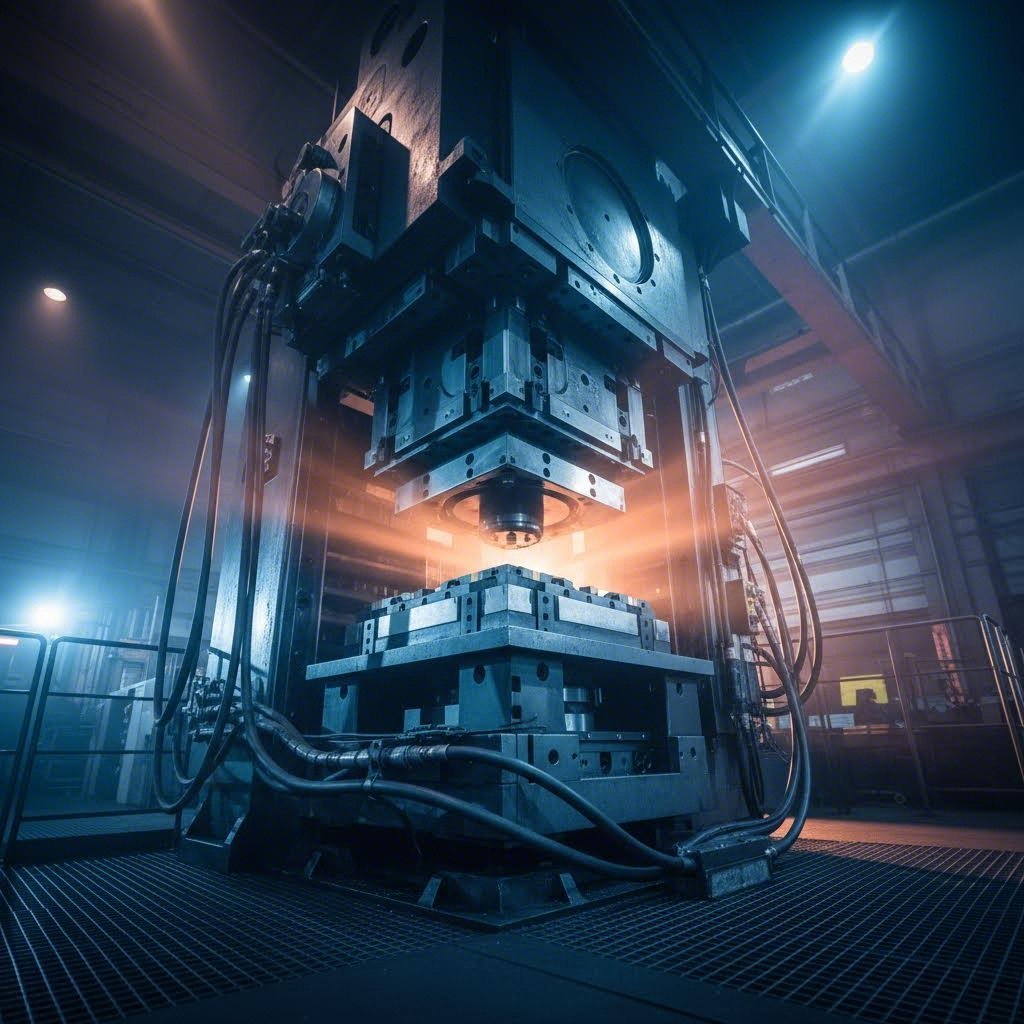
Muotti on erikoistunut työkalu, jota käytetään materiaalin leikkaamiseen, muotoilemiseen tai muovaukseen tiettyihin muotoihin voiman vaikutuksesta, yleensä yhdessä puristimen kanssa raaka-aineiden muuntamiseksi valmiiksi komponenteiksi.
Ajattele sitä näin: kun käytät keksimuottia, painat muotoiltua työkalua taikinapalloon luodaksesi identtisiä muotoja. Teollisuudessa käytetyt muotit toimivat samalla periaatteella, mutta ne käsittelevät metallia, muovia ja muita teollisia materiaaleja tarkkuudella, joka mitataan tuhannesosain tuumina.
Mukaan lukien Wikipedia:n valmistusresurssit muovausmuottien valmistus tapahtuu yleensä työkalu- ja muottimiehien toimesta, ja ne otetaan käyttöön asennettuna puristimeen. Tämä muotin ja puristimen välinen yhteistyö mahdollistaa suurten tuotantomäärien valmistuksen.
Valmistusmuottien keskeinen tehtävä
Tässä asiasta tulee mielenkiintoista. Muotti toimii halutun osan negatiivisena tai käänteisenä muotona. Kuvitellaan esimerkiksi kaarevaa metallitukia, jota halutaan valmistaa. Muotti sisältää täsmälleen vastakkaisen muodon, joten kun materiaali pakotetaan sen vastalle, tuloksena on haluttu muoto.
Muottia käytetään useiden kriittisten toimintojen suorittamiseen:
- Leikkaus ja rei'itys - leikkaamaan muotoja levyraaka-aineesta tai tekemään reikiä
- Kääntyminen - muovaamaan kulmia ja kaaria tasaisesta raaka-aineesta
- Piirustus - venyttämään materiaalia kolmiulotteisiin muotoihin
- Muodostaa - muokkaamaan materiaalia puristamalla, venyttämällä tai käyttämällä molempia menetelmiä
Käytettäväksi auton kehysten osat tässä prosessissa on kaksi pääkomponenttia, jotka toimivat yhdessä. Työkalupistin suorittaa venytys-, taivutus- ja leikkaustoimenpiteitä, kun taas muottipidin kiinnittää työkappaleen turvallisesti ja tarjoaa täydentävän muotoilutoiminnon. Työkappale voi kulkea useiden vaiheiden läpi eri työkalujen avulla saavuttaakseen lopullisen muotonsa.
Miksi muotit ovat tärkeitä nykyaikaisessa tuotannossa
Miksi die-laadulla on merkitystä? Koska se vaikuttaa suoraan kolmeen asiaan, jotka vaikuttavat liiketoiminnan kannattavuuteen: osien yhdenmukaisuuteen, tuotantonopeuteen ja kustannustehokkuuteen.
Kun valitset oikean muotin valmistuksessa, paranee tuotteen laatu ja romuaste pienenee. Hyvin suunniteltu muotti vähentää osien paksuusvaihteluita, säilyttää tiukat toleranssit ja saavuttaa erinomaiset pinnanlaatutasot. Toisaalta epäsoveltavan muotin valinta johtaa merkittäviin haasteisiin, kuten tuotannon viivästymiin ja jätteen määrän kasvuun.
Muottien valmistus vaikuttaa myös merkittävästi käyttökustannuksiisi. Oikea muotti vähentää materiaalihävikkiä, minimoi käyttökatkoja ja pidentää työkalun käyttöikää. Muotin valinta vaikuttaa myös tuotantonopeuteen ja läpimenoaikaan, mikä mahdollistaa korkeamman tuotantonopeuden säilyttämisen samalla kun varmistetaan johdonmukainen laatu.
Tässä artikkelissa tutustut muottien koko valmistusprosessiin: eri sovelluksia varten saatavilla olevat muottityypit, niiden kestävyyden takaavat materiaalit, tarkkuustyökalujen valmistusmenetelmät, tärkeimmät toleranssit sekä huoltotoimet, joilla voidaan saavuttaa mahdollisimman pitkä käyttöikä. Riippumatta siitä, arvioitko muottisijoituksia vai valitsetko valmistuskumppania, seuraavat tiedot auttavat sinua tekemään päätöksiä varmuudella.
Muottityypit, joita käytetään valmistustoiminnassa
Nyt kun tiedät, mitä muottikappaleita ovat ja miksi ne ovat tärkeitä, tutkitaan erilaisia muottikappaleita, joihin valmistajat luovat päivittäin. Oikean leikkausmuotin valinta sovellukseesi voi tarkoittaa eroa kannattavien tuotantosarjojen ja kustannusintensiivisten takaiskujen välillä. Jokainen muottityyppi tarjoaa omat erityisominaisuutensa, ja näiden erojen ymmärtäminen auttaa sinua tekemään viisaampia työkaluinvestointeja.
Edistävät muotit ja moniasemaiset toiminnot
Kuvittele metallijuota kulkevan koneen läpi kuin matkustajat kulkevat lentokentän turvatarkastuspisteiden läpi. Jokaisessa asemassa tapahtuu jotain tiettyä ennen kuin juota siirtyy seuraavaan asemaan. Täsmälleen näin edistävät muotit toimivat.
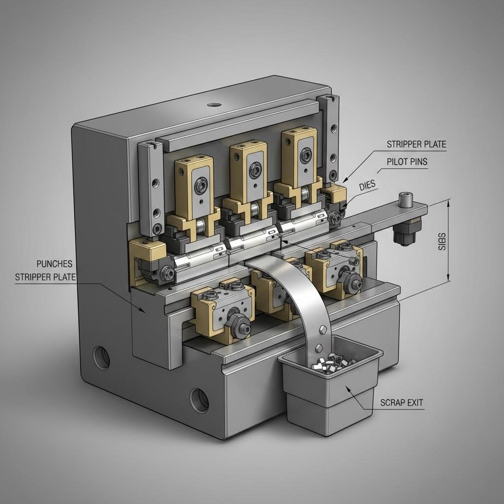
In progressiivinen muottileimaus kierukkamainen metallin nauha syötetään muottipressiin ja liikkuu sarjan leikkausasemien läpi. Jokainen asema suorittaa eri toimenpiteen, olipa kyseessä poraus, taivutus, muotoilu tai reunojen leikkaus. Työkappale pysyy kiinni perusnauhassa koko prosessin ajan, ja erottaminen tapahtuu vasta viimeisenä vaiheena.
Tässä on mitä tekee tästä painomuotista erityisen tehokkaan:
- Tarkka hallinta - Nauhassa olevat etukäteen poratut ohjausreiät mahdollistavat kartiomaisien ohjainten tarkan materiaalin pitämisen sen edetessä
- Nopea tuotanto - Osat liikkuvat automaattisesti asemien välillä ilman manuaalista käsittelyä
- Johdonmukainen toisto - Jokainen osa kulkee samanlaisen toimenpiteiden sarjan läpi samassa järjestyksessä
- Alennetut työvoimakustannukset - Automatisointi poistaa manuaalisen osien siirron toimenpiteiden välillä
Edistävä leikkausmuotti soveltuu erinomaisesti suurten määrien pienempien, mutta monimutkaisten geometrioiden omaavien osien valmistukseen. Tämä kuitenkin vaatii merkittävän alustavan työkaluinvestoinnin ja ei sovellu osiin, joissa vaaditaan syvän vetämisoperaatioita.
Siirtomuotit monimutkaisten osien käsittelyyn
Mitä tapahtuu, kun osasi ovat liian suuria tai monimutkaisia etenevien muottien käyttöön? Siirto-muottipursotus täyttää tämän aukon.
Erilaisten etenevien prosessien tapaan, joissa osat pysyvät yhteydessä metallikaistaa, siirto-muottipursotuksessa jokainen osa erotetaan ensin kaistasta. Yksittäiset osat siirtyvät sitten mekaanisten "sormien" tai automatisoitujen kuljetusjärjestelmien avulla erillisiin muottiasemiin. Ajattele tätä kokoonpanolinjana, jossa jokainen asema tuottaa jotakin tiettyä lopulliseen tuotteeseen.
Tämä lähestymistapa tarjoaa merkittävää joustavuutta:
- Käsittelee suurempia komponentteja - Kotelot, kehikot ja rakenteelliset osat, jotka eivät mahdu eteneviin muotteihin
- Mahdollistaa syvän vetäytyksen - Koska kaistaa ei ole kiinni, puristin voi leikata niin syvälle kuin materiaali sallii
- Tukee monimutkaisia suunnitteluratkaisuja - Ominaisuudet kuten kierrepiirteet, ripset ja kierreputket tulevat mahdollisiksi
- Sallii erilaiset asennot - Osia voidaan siirtää uudelleen eri toimintojen välillä
Siirtoleipäys toimii hyvin sekä lyhyille että pitkille tuotantosarjoille. Kuitenkin käyttökustannukset ovat usein korkeammat monimutkaisempien asetusten ja huollon vaatiman koulutetun työvoiman vuoksi. Monimutkaisten osien asennusaika voi myös venyttää tuotantoaikataulua.
Yhdistelmä- ja yhdistettyjä leikkureita
Joskus tarvitaan useita toimintoja suoritettavaksi yhdellä puristuspulssilla. Tässä yhdistelmäleikkurit loistavat.
Teollisuuslähteiden mukaan yhdistelmäleikkurileipäys suorittaa useita leikkuuja, reikäyksiä ja taivutuksia samanaikaisesti eikä peräkkäin. Tämä tekee niistä erityisen tehokkaita yksinkertaisten tasapintojen, kuten pesukkeiden, valmistukseen, jossa nopeus ja tarkkuus ovat tärkeimmät tekijät.
Yhdistettyjen työkaluleikkureiden keskeiset edut ovat:
- Korkeampi tasaisuuden tarkkuus - Yksittäisen pulssin toiminnot säilyttävät paremman mittatarkkuuden
- Tehokas materiaalin käyttö - Vähemmän jätteitä verrattuna monipulssisiin prosesseihin
- Kustannustehokas keskikokoisille tuotantomääriälle - Alhaisemmat kappalekohtaiset kustannukset soveltuvissa käyttötapauksissa
- Nopeampia kiertosyklejä - Yhdellä iskulla saadaan valmiiksi se, mikä muuten vaatisi useita eri toimintoja
Yhdistelmämuottien avulla yhdistetään sekä monitoimimuottien että etenevän muottausmenetelmän elementtejä, mikä tarjoaa joustavuutta osille, joille vaaditaan sekä samanaikaisia että peräkkäisiä toimintoja.
Eri muottityyppien vertailu sovellukseenne
Oikean leikkausmuotin valinta edellyttää, että osavaatimukset sovitetaan kunkin muottityypin vahvuudet huomioiden. Seuraavassa vertailussa käydään läpi keskeiset erot:
| Nelosuunnikksen tyyppi | Parhaat käyttösovellukset | Tuotantotilavuuden soveltuvuus | Monimutkaisuustaso |
|---|---|---|---|
| Edistynyt kuumapaineisto | Pienet ja keskikokoiset osat monimutkaisilla geometrioilla; sähkökomponentit, kiinnikkeet, liittimet | Suuri tuotantomäärä (yli 100 000 kappaletta) | Kohtalainen–korkea; kykenee käsittelämään useita toimintoja peräkkäin |
| Siirto-muotti | Suuret osat, syvälle vetätyt komponentit, kuoret, kehykset, rakenteelliset osat, joissa on nurjahduksia tai kierrekierteitä | Keskikokoinen–korkea tuotantomäärä; joustava erilaisille tuotantosarjoille | Korkea; soveltuu monimutkaisiin suunnitteluun ja asentoihin |
| Yhdistetty leikkausvarsi | Yksinkertaiset tasaiset osat, kuten varraskiekot, etäisyyspalat ja peruslevyt, joille vaaditaan korkeaa tarkkuutta | Keskitaso mittava, suuri | Alhainen–kohtalainen; yksiosaiset iskutoiminnot |
| Yhdistelmämuotti | Osat, jotka vaativat sekä samanaikaisia että peräkkäisiä toimintoja | Keskikokoinen sarja | Kohtalainen; yhdistää yhdistelmä- ja edistävän muottityypin ominaisuuksia |
Pääasialliset tekijät, jotka vaikuttavat valintaanne, liittyvät kolmeen seikkaan: osan kokoon ja monimutkaisuuteen, vaadittuun tuotantomäärään ja budjettirajoituksiin. Edistävät muotit vaativat korkeampaa alustavaa investointia, mutta tuottavat mittakaavan kasvaessa alhaisemmat kustannukset osaa kohden. Siirtomuotit tarjoavat joustavuutta monimutkaisille osille, mutta niiden käyttökustannukset ovat korkeammat. Yhdistelmämuotit tasapainottavat nopeutta ja tarkkuutta yksinkertaisemmissa geometrioissa.
Kun et ole varma, mikä menetelmä sopii projektillesi parhaiten, kokemuksellisen muottivalmistajan kanssa työskentely auttaa selkiyttämään paras eteenpäin vievä tie. Näiden muottien todellisen valmistuksen ymmärtäminen antaa vielä syvempää näkemystä siitä, mitä erottaa laadukkaat muotit muista.
Kuinka muotteja valmistetaan
Olette siis valinneet työkalun tyypin. Mutta oletteko koskaan miettineet, mitä tapahtuu tilauksen antamisen ja miljoonia identtisiä osia tuottavan tarkkuustyökalun saamisen välillä? Työkalunvalmistusprosessi muuttaa raakateräksestä työkaluja, joiden toleranssit mitataan mikrometreissä. Tämän matkan ymmärtäminen auttaa arvostamaan, miksi laadukkaat työkalut ovat kalliita ja miksi kulmien leikkaaminen valmistuksen aikana johtaa kalliisiin tuotantovirheisiin.
Jokainen taitava työkalunvalmistaja noudattaa systemaattista lähestymistapaa, joka tasapainottaa insinöörimäistä tarkkuutta ja käytännön valmistusrajoituksia . Tässä on täydellinen järjestys käsitteestä tuotantovalmiiseen työkaluun:
- Suunnittelu- ja tekninen vaihe - CAD-mallinnus, simulointi ja suunnittelun validointi
- Tarkkuuskoneistus ja valmistus - CNC-koneistus, EDM, hiominen ja komponenttien valmistus
- Lämpökäsittely ja pintakäsittely - Karkaisuprosessit ja pinnan esikäsittely
- Kokoonpano ja laadun testaus - Lopullinen kokoonpano, kokeilu ja validointimenettelyt
Käydään läpi jokainen vaihe, jotta näemme, miten raaka-aine muuttuu tuotantovalmiiksi muotiksi.
Suunnittelu- ja tekninen vaihe
Ennen kuin mitään metallia leikataan, muottimestari panostaa merkittävän ajan suunnitteluvaiheeseen. Tämä vaihe määrittää kaiken sen, mikä seuraa, ja tässä vaiheessa tehtyjä lyhyitä polkuja kertautuu myöhemmin suuriksi ongelmiksi.
Nykyajan muottien koneistus alkaa tietokoneavusteisella suunnittelulla (CAD), jossa luodaan yksityiskohtaiset 3D-mallit kaikista komponenteista. Alan asiantuntijoiden mukaan insinöörit käyttävät näitä malleja määrittääkseen vaaditun muodon, koon ja toiminnallisuuden perustuen siihen, mitä osia muotti tuottaa. Suunnitteluvaiheessa otetaan huomioon tekijöitä, kuten materiaalin valinta, välykset ja kyseessä oleva tarkka valmistusprosessi.
Mikä tekee tästä vaiheesta ratkaisevan tärkeän? Harkitse näitä keskeisiä näkökohtia, joita insinöörien on käsiteltävä:
- Osa-alueen geometrian analyysi - Ymmärtäminen siitä, miten valmiin komponentin muoto vaikuttaa muotin monimutkaisuuteen
- Materiaalin virtausmallinnus - Ennustaminen siitä, miten metalli käyttäytyy muovauksessa
- Toleranssitarkkuuden määrittely - Määrittämään tarkkuusvaatimukset jokaiselle muottikomponentille
- Jännitysanalyysi - Tunnistamassa mahdolliset viankohtakohdat ennen kuin ne aiheuttavat tuotantoon liittyviä ongelmia
Simulointiohjelmisto mahdollistaa suunnittelujen virtuaalisen testaamisen ennen kalliiden työkaluteräsmuottien valmistusta. Tämä validointivaihe havaitsee ongelmat varhaisessa vaiheessa, jolloin muutokset maksavat minuutteja eivätkä viikkoja.
Tarkkuuskoneistus ja valmistus
Kun suunnittelu on valmis, paperilla muodostettu muotti täytyy muuntaa fyysiseksi todellisuudeksi. Tässä vaiheessa edistyneet valmistuslaitteet muuntavat kovennettujen teräspalojen lohkot tarkkuuskomponenteiksi.
CNC-jyrsintäkoneet hoitavat alustavan muotoilutyön ja leikkaavat muottimateriaalin tarkasti suunnitellun geometrian mukaiseksi. Nämä tietokoneella ohjattavat koneet saavuttavat toleranssit, jotka ovat mahdottomia manuaalisilla menetelmillä, ja varmistavat, että jokainen piirre vastaa CAD-mallia täsmälleen.
Mutta yksinään jyrsintä ei pysty luomaan kaikkia muotin vaatimia piirteitä. Lisäksi käytettäviä koneistusmenetelmiä ovat:
- Sähköisen laskutusmallin (EDM) käyttö - Käyttää sähkökärkiä materiaalin poistamiseen, mikä on välttämätöntä monimutkaisten yksityiskohtien ja kovennettujen pintojen valmistamiseksi, joita perinteiset leikkuutyökalut eivät pysty käsittelyyn
- Jyrsiminen - Tasaa ja viimeistää muottipintoja saavuttaakseen tarkat mitat ja pinnanlaadun
- Poraus ja kouraaminen - Tekee reikiä jäähdytyskanavien, työntöjärjestelmien ja kiinnityskappaleiden käyttöön
- Lanka EDM - Leikkaa monimutkaisia profiileja erinomaisella tarkkuudella ohuen langanelektrodin avulla
Muottien koneistusvaihe edustaa usein suurinta osaa valmistusajasta ja -kustannuksista. Monimutkaiset edistävät muotit voivat vaatia satoja tuntia CNC-koneistusta useilla eri koneilla ennen kuin kaikki komponentit ovat valmiita seuraavaan vaiheeseen.
Lämpökäsittely ja pintakäsittely
Raakakoneistettu teräs ei ole tarpeeksi kovaa kestämään miljoonia tuotantokierroksia. Lämmönkäsittely muuttaa materiaalin ominaisuuksia luodakseen muotin, joka toimii äärimmäisissä olosuhteissa.
Mukaan lukien SECO/WARWICK -tutkimus teollisuuden standardit, kuten NADCA:n määrittelemät, vaativat tyhjiöuunissa suoritettavaa lämmönkäsittelyä korkeapaineisella kaasujäähdytyksellä. Prosessi edellyttää tarkkaa lämpötilan säätöä sekä pinnan että ytimen lämpötilan seurantaa koko prosessin ajan.
Lämpökäsittelyprosessi sisältää yleensä seuraavat vaiheet:
- Ennakkoväritys - Vaiheittainen lämpötilan nosto austeniittiseen lämpötilaan pidot 590–680 °C:n ja 815–860 °C:n lämpötiloissa varmistaakseen tasaisen kuumennuksen
- Austeniitointi - Pito noin 1030 °C:ssa vähintään 30 minuuttia lämpötilan tasaisuuden saavuttamiseksi
- Kuohennus - Nopea jäähdytys vähintään 28 °C/min nopeudella estääkseen epätoivottavan raerajan saostumisen
- Kärsytys - Useita kovuuden alentamiseen ja kohdekovuuden 42–52 HRC saavuttamiseen tähtääviä pehmennyskertoja vähintään 565 °C:ssa
Pintakäsittely suoritetaan lämmönkäsittelyn jälkeen muottien suorituskyvyn optimoimiseksi. Yleisiä menetelmiä ovat kiillotus kitkan vähentämiseksi, pinnoitus korroosion estämiseksi ja metallipinnoitus käyttöikään vaikutavan kestävyyden parantamiseksi. Hyvin valmistettu muotti tuottaa osia sileällä pinnalla ja vastustaa materiaalin kertymistä, joka aiheuttaa virheitä.
Kokoonpano ja laadun testaus
Yksittäisten muottiosien on muodostettava toimiva kokonaisuus. Kokoonpanovaihe vaatii kokemuksetta omaavia teknikkoja, jotka ymmärtävät, miten jokainen osa vuorovaikuttelee muiden osien kanssa.
Kokoonpano sisältää muottiosien asentamisen muottisarjaan, jäähdytysjärjestelmien asennuksen, poistomekanismien kiinnittämisen sekä kaikkien elementtien suuntaamisen suunnittelun mukaisesti. Jo pienikin epäsuuntautuminen tällä vaiheella johtaa osien vikoittumiseen tuotannossa.
Ennen kuin mikään muotti siirtyy tuotantoon, sen suorituskyky testataan laajasti:
- Mitallisen vahvistuksen - Varmistetaan, että kaikki komponentit täyttävät määritellyt toleranssit
- Kokeilukäynnöt - Otososien valmistaminen muottisuorituskyvyn arviointia varten
- Ostososien tarkastus - Otososien mittaus suunnittelun mukaisiin eritelmäihin
- Säätö ja kalibrointi - Muottielementtien hienosäätö tuotannon laadun optimoimiseksi
Testaus paljastaa usein alueita, jotka vaativat säätöjä. Luotettava muottienvalmistaja odottaa tätä iteroivaa prosessia ja varaa aikaa hioonten ja tarkistusten tekemiseen aikataulussaan. Testausta ei pidä kiihdyttää määräpäivän saavuttamiseksi, sillä tämä johtaa yleensä tuotantoon liittyviin ongelmiin, joiden korjaaminen myöhemmin maksaa huomattavasti enemmän.
Kun valmistusprosessi on valmis, muottisi on valmis tuotantokäyttöön. Kuitenkin suunnitteluvaiheessa valitut materiaalit vaikuttavat merkittävästi siihen, kuinka kauan muotti kestää ja millaista laadukkuutta osat ovat.
Muottimateriaalit ja valintakriteerit
Olet nähnyt, miten muotteja valmistetaan, mutta tässä on kysymys, joka erottaa hyvän työkaluvalmistuksen erinomaisesta työkaluvalmistuksesta: mistä materiaaleista nämä muotit tulisi valmistaa? Valitsemasi teräsmuotti määrittää kaiken – tuotantokustannukset, osien laatu sekä sen, kuinka monta käyttökertaa työkalu kestää ennen uusimista. Työkalu- ja muottimateriaalien ymmärtäminen auttaa sinua tekemään päätöksiä, jotka tuovat hyötyjä koko tuotantoketjullesi.
Ajattele asiaa näin. Muottia, joka kuluu 50 000 käyttökerran jälkeen, saattaa aluksi vaikuttaa edullisemmalta, mutta kun sinun täytyy vaihtaa sitä kahdesti 150 000 osan tilauksen valmistumiseksi, säästöt katoavat nopeasti. Termi 'muotti ja työkalu' käsittää enemmän kuin pelkän leikkaamisen ja muovauksen; se kattaa myös materiaalien ominaisuuksien ja valmistuksen tulosten välisen kokonaisuuden.
Työkaluteräslaatut ja niiden käyttöalueet
Ei kaikki muottiteräkset kestävät valmistusrasitetta yhtä hyvin. Jokainen laatu tarjoaa ainutlaatuisen tasapainon kovuuden, kulumisvastuksen ja sitkeyden välillä, ja se on suunnattu tiettyihin sovelluksiin. Ryersonin työkaluteräkseen liittyvien resurssien mukaan yleisimmät laadut, kuten A2, D2, O1, S7, H13 ja M2, ovat keskeisiä perustyökalujen ja koneiden muottien valmistuksessa.
Tarkastellaan yleisimmin käytettyjä vaihtoehtoja:
- H13 (kuumatyöteräs) - Teollisuuden työhevonen alumiini- ja sinkkivalugosille. Se kovettuu 44–52 HRC:ksi ja kestää käyttölämpötiloja jopa 600 °C:seen asti. Lämmönjohtavuus on noin 24 W/m·K ja Charpyn iskunenergia 22–26 J, mikä tekee H13:sta erinomaisen tasapainon lujuuden, sitkeyden ja kuumuudenkestävyyden välillä.
- D2 (korkean hiilipitoisuuden ja korkean kromipitoisuuden teräs) - Ihanteellinen kylmämuokkaussovelluksiin, joissa kulutuskestävyys on tärkeintä. Newayn materiaaliohjeen mukaan D2 kovettuu 58–62 HRC:ksi ja sen kromipitoisuus on noin 12 %. Se soveltuu erinomaisesti leikkaus- ja viimeistelytyökaluihin ohuille levymetalleille, mutta sen suorituskyky on heikko lämpösyklattavissa ympäristöissä.
- A2 (ilmassa kovettuva työkaluteräs) - Yhdistää kulutuskestävyyden ja sitkeyden. Se kovettuu 56–60 HRC:ksi, tarjoaa hyvän mitallisen vakauden ja koneistettavuuden sekä kohtalaisen iskunkestävyyden. Se soveltuu hyvin yleiskäyttöisiin muottien ja muovaustyökalujen valmistukseen.
- S7 (iskunkestävä työkaluteräs) - Kun muottisi kokee toistuvaa iskukuumaa ja mekaanista iskua, S7 on ratkaisu. Se kovettuu 54–56 HRC:ksi ja tarjoaa erinomaista iskunkestävyyttä ilman haurautta. Tätä laadukasta terästä hyödynnetään parhaiten leikkuumuotteihin, painomuotteihin ja muuhun iskuvoimaisiin käyttöön.
- P20 (esikovennettu muottiteräs) - Kustannustehokas keskimittaisen kovuuden vaatimuksiin. P20 on esikovennettu 28–32 HRC:ksi, mikä tekee siitä helppokäyttöisen koneistettavaksi ja hiottavaksi. Se soveltuu prototyyppimuotteihin, lyhyille tuotantosarjoille ja sovelluksiin, joissa käyttölämpötila pysyy alle 400 °C:ssa.
Jokainen metallimuottimateriaali edustaa kompromissia. Korkeampi kovuus tarkoittaa yleensä pienentynyttä sitkeyttä. Parempi kulumiskestävyys saavutetaan usein huonommalla koneistettavuudella. Näiden suhteiden ymmärtäminen auttaa sinua valitsemaan optimaalisen teräsmuotin tiettyyn käyttöön.
Karbidit ja edistyneet materiaalit
Milloin standardit työteräkset eivät riitä? Korkean kulumisen ympäristöissä ja vaativissa tuotanto-olosuhteissa edistyneet materiaalit oikeuttavat korkeamman hinnan merkittävästi pidennetyllä käyttöiällä.
Mukaan lukien Otsikon analyysi , kovametallitulpat ovat parhaiten sopivia pitkille tuotantosarjoille ja kovemmille muokattaville materiaaleille, joiden seostusaste on korkeampi. Volframikovametalli on saatavilla eri laaduissa, jotka luokitellaan kobolttipitoisuuden mukaan, tyypillisesti 6 %, 10 %, 12 %, 15 %, 20 % ja 25 %. Kun kobolttiprosentti kasvaa, kovuus pienenee, mutta iskunkestävyys paranee.
Kovametalli on järkevä valinta, kun:
- Pitkäkestoiset tuotantosarjat - tuotat miljoonia osia, jolloin kovametallin pidempi käyttöikä kompensoi sen korkeamman hinnan
- Hioma-aineet - korkeaseostuiset työkappaleet kuluttavat terästulpat nopeasti, mutta vaikuttavat kovametalliin vain vähän
- Tiukat toleraatiivaatimukset - kovametalli säilyttää mittojen vakauden pidempään kuin teräsvaihtoehdot
- Korkean kulumisen vaativat sovellukset - leikkuutulpat ja leikkuutyökalut hyötyvät kovuudesta, joka ylittää 80 HRC:n
Kovametallin lisäksi erikoismateriaalit ratkaisevat tiettyjä haasteita:
- Berylliumkupari (BeCu) - Kovan 35–45 HRC -kovuuden ja lämmönjohtavuuden, joka voi olla jopa 110 W/m·K, ansiosta berylliumkupari (BeCu) soveltuu erinomaisesti sovelluksiin, joissa vaaditaan nopeaa lämmön poistamista. Ydinnaulat, liukupinnat ja sisäosat muovin suurpainossa tai sinkin valussa hyötyvät sen erinomaisesta kiillottavuudesta ja korroosionkestävyydestä.
- Inconel 718 - Tämä nikkeli-pohjainen ylikuumaluokan seos kestää lämpötiloja, joissa perinteiset teräkset epäonnistuvat. Inconel-teräs kestää vetomurtolujuuden, joka voi olla jopa 1240 MPa 700 °C:ssa, ja sillä on erinomainen kriipymisvastus; sitä käytetään kuparin ja messinkin muottivalussa.
Terässisäkkäät ovat parhaiten sopivia lyhyille ja keskipitkille tuotantosarjoille, joissa toimitusaika on ratkaiseva tekijä. Niitä voidaan työstää nopeasti, niiden alkuhinta on alhaisempi ja niiden asennus on nopeampaa. Karbidisisäkkäät edellyttävät suurempaa alkupanosta, mutta ne tuottavat hyötyjä vähentämällä huoltotarvetta ja tuotantoa keskeyttäviä katkoja.
Materiaalin valintakriteerit
Miten valitaan materiaalit tiettyihin vaatimuksiin? Useat tekijät ohjaavat tätä päätöstä:
- Tuotannon määrä - Suuremmat tuotantomäärät oikeuttavat kalliimmat materiaalit, joilla on pidempi käyttöikä
- Osan materiaali - Kova-aineiset tai korkean seoslisäaineen sisältävät työkappaleet vaativat kovempia muottiosia
- Toimintatemperatuuri - Kuumat työsovellukset vaativat materiaaleja, joilla on hyvä lämpövakaus
- Tarkkuusvaatimukset - Tarkemmat toleranssit edellyttävät materiaaleja, joilla on hyvä mitallinen vakaus
- Budjettivirheet - Alkuperäinen kustannus verrattuna kokonaishuollon kustannukseen vaikuttaa laskelmaan
Seuraava vertailu tiivistää tärkeimmät muottimateriaalit ja niiden ominaisuudet:
| Materiaalilaji | Kovuusalue | Kulutuskestävyys | Kestävyys | Tyypilliset sovellukset |
|---|---|---|---|---|
| H13-työkaluteräs | 44–52 HRC | Kohtalainen-korkea | Korkea | Alumiini-/sinkkivalumuotit, suurpainevalumuotti, muovin ruiskutusmuottaus |
| D2-Työkaluteräs | 58–62 HRC | Erittäin korkea | Alhainen | Kylmän työn muottien valmistus, leikkausmuottien valmistus, reunojen viimeistelyyn käytettävät muotit |
| A2-työkaluteräs | 56-60 HRC | Korkea | Kohtalainen | Yleiskäyttöiset muotit ja muovausvälineet |
| S7-työkaluteräs | 54–56 HRC | Kohtalainen | Erittäin korkea | Iskunkestävät muotit, puristustyökalut |
| P20-muottiteräs | 28-32 HRC | Matala-Kohtalainen | Korkea | Prototyyppimuotit, lyhyen tuotantosarjan työkalut |
| Volframikarbidi | >80 HRC | Erinomainen | Alhainen | Korkean kulutuksen kestävät kiinnityskappaleet, pitkäikäiset leikkuutyökalut |
| Berylliokoppari | 35–45 HRC | Kohtalainen | Korkea | Ytimen pinnat, liukupinnat, lämmönkriittiset sisäosat |
| Inconel 718 | Muuttuja | Korkea | Kohtalainen | Kupari-/messinkivalu, lämpöytimeen tarkoitetut sisäosat |
Materiaalin valinta vaikuttaa suoraan muottien kestoon ja tuotettujen osien laatuun. Materiaaliominaisuuksien ja sovellusvaatimusten välinen epäsovitteisuus johtaa ennenaikaiseen kulumiseen, mittojen poikkeamiseen ja pinnan virheisiin valmiissa komponenteissa. Ajan investointi oikeaan materiaalinvalintaan tuottaa hyötyjä koko tuotantohankkeen ajan.
Kun materiaalit on valittu viisaasti, seuraava tarkasteltava asia on ymmärtää, miten eri teollisuudenalat käyttävät näitä muottikomponentteja vastatakseen omia valmistusprosessiinsa liittyviä haasteita.
Teollisuudenalat, joissa käytetään valmistusmuotteja
Olet oppinut tietämään muottityypeistä, valmistusprosesseista ja materiaaleista. Mutta tässä teoria kohtaa todellisuuden: miten eri teollisuudenalat käyttävät näitä työkaluja käytännössä? Muottien valmistusteollisuus palvelee huomattavan monipuolisia aloja, ja jokainen ala asettaa omat erityisvaatimuksensa, jotka vaikuttavat kaikkeen – materiaalien valinnasta tarkkuusvaatimuksiin asti. Näiden alakohtaisten vaatimusten ymmärtäminen auttaa sinua arvostamaan sitä, miksi autoalan tuotannossa käytettävä muotti ei näytä lainkaan samalta kuin lääkintälaitteisiin tarkoitettu muotti.
Ajattele asiaa näin: metallilevyjen muovaukseen tarkoitettu muottiratkaisu, joka toimii täydellisesti kodinkoneiden koteloiden valmistukseen, saattaa epäonnistua katastrofaalisesti lentokonekomponenttien valmistuksessa. Riskitaso, standardit ja vaatimukset vaihtelevat merkittävästi eri aloilla. Tutkitaan, mikä tekee jokaisen alan vaatimukset erilaisiksi.
Autoteollisuuden leikkuumuottivaatimukset
Kun otetaan huomioon, että yhdessä ajoneuvossa on 3 000–10 000 leimattua osaa, autoteollisuuden muottitoimintojen laajuus tulee selväksi. Tämä teollisuus vaatii työkaluja, jotka toimivat johdonmukaisesti miljoonien tuotantokierrosten ajan ja säilyttävät tarkkuudet niin tiukkoina, että jokainen paneeli istuu täydellisesti kokoonpanovaiheessa.
Mukaan lukien SEYI:n edistävän muotin määrittelyt , autoteollisuuden sovellukset vaativat puristimia, jotka pystyvät suorittamaan vetämis-, muovaus-, leikkaus-, reiäitys- ja leikkaustoimintoja ja täyttävät kehityksen kohti kevyempiä, korkean vetolujuuden teräksisiä osia. Nykyaikaiset ajoneuvot käyttävät yhä enemmän edistyneitä korkealujuusteräksiä (AHSS), mikä asettaa haasteita perinteisille muottisuunnittelumenetelmille.
Mikä tekee autojen muotteja ja puristusta erityisen vaativaa? Otetaan esimerkiksi auton oven kappale. Sen on täsmättävä viereisiin kappaleisiin murto-osan millimetriä tarkemmin, sen paksuuden on pysyttävä yhtenäisenä rakenteellisen kestävyyden varmistamiseksi ja sen pinnan on oltava riittävän sileä maalin tarttumisen varmistamiseksi. Mikään poikkeama ei ole sallittu, sillä se johtaisi näkyviin aukkoihin, huonoon aerodynamiikkaan tai turvallisuusongelmiin.
- Tilavuustarpeet - Yksittäiset muottisarjat tuottavat usein 500 000–1 000 000+ kappaletta niiden käyttöiän aikana
- Materiaalikysymykset - AHSS- ja alumiiniseokset vaativat kovempia muottimateriaaleja ja tarkkoja välejä
- Toleranssistaandardit - Kappaleet yleensä vaativat ±0,1 mm:n tai tiukempaa mittatarkkuutta
- Pinnan laatuvaatimukset - Luokan A -pinnat vaativat kiillotettuja muottipintoja ja ohjattua materiaalin virtausta
- Kierroksenaikaan liittyvät paineet - Korkean nopeuden edistävät muotit on suunniteltava siten, että laatu säilyy 30–60+ iskua minuutissa
- IATF 16949 -sopus - Laatujärjestelmän sertifiointi vaaditaan suurilta OEM-valmistajilta
Myös autoteollisuuden muottiala kohtaa painetta lyhentää työkalujen valmistusajoissa samalla kun ensimmäisen kerran hyväksyttyjen osien osuutta parannetaan. Simulaatio-ohjelmistot auttavat ennustamaan muotoilukäyttäytymistä ennen teräksen leikkaamista, mutta kokemukset muottimiehet tarjoavat edelleen korvaamatonta tietoa käytännön valmistusrajoituksista.
Ilmailu- ja lääketieteelliset tarkkuusstandardit
Jos autoteollisuuden toleranssit vaikuttavat vaativilta, niin ilmailu- ja lääketieteelliset sovellukset vievät tarkkuuden täysin toiselle tasolle. Kun komponenttien on toimittava äärimmäisissä olosuhteissa tai ihmisen kehossa, virhemarginaali lähestyy nollaa.
JBC Technologiesin ilmailun tarkkuusoppaan mukaan ilmailualan tarkkuus ei ole vain muodillinen ilmaisu. Haastavista käyttöolosuhteista kalliisiin kuormiin saakka leikattujen ilmailukomponenttien on toimittava olosuhteissa, jotka ovat paljon vaativampia kuin tyypillisissä teollisuussovelluksissa. Pienetkin poikkeamat voivat johtaa epätasaiseseen kattaukseen elintärkeissä komponenteissa, mikä lisää turvallisuusriskejä ja aiheuttaa kalliita uudelleensuunnittelutöitä.
Ilmailualan ala tarjoaa ainutlaatuisia haasteita kaikille metallisovelluksien leikkuutyökaluille:
- Vieras materiaaleja - Titaani, Inconel ja erikoisalumiiniseokset vaativat kovametallia tai edistyneitä leikkuutyökalumateriaaleja
- Erinomaiset tarkkuusvaatimukset - Kriittiset mitat on usein pidettävä ±0,025 mm:n tarkkuudella tai tiukemmin
- Jäljitettävyysvaatimukset - Jokainen osa on yhdistettävä tiettyihin materiaalieriin ja tuotantokierroksiin
- Monikerroksiset kokoonpanot - Lämmöneristys ja EMI/RFI-suojaus vaativat tarkkaa mitallista hallintaa kerrosten välillä
- AS9100-sertifiointi - Laatujärjestelmät, jotka on suunniteltu erityisesti ilmailualan valmistukseen
- Laajennetut kvalifiointiprosessit - Uusien leikkuutyökalujen hyväksyntään tuotantoon saattaa kulua kuukausia validointiprosessin jälkeen
Lääkintälaitteiden valmistus vaatii samanlaista tarkkuutta kuin ilmailuala, mutta lisäksi on otettava huomioon biokompatibilisuus. Ihmisen kudoksiin koskettavien komponenttien on täytettävä Yhdysvaltojen elintarvike- ja lääkeviraston (FDA) määräykset, ja niiden valmistus vaatii usein puhtaiden tilojen käyttöä. Teollisten leikkuukoneiden käyttö lääkintäalan sovelluksissa liittyy usein erityisiin ruostumattomiin teräksiin, titaaniin ja polymeerimateriaaleihin, jotka asettavat haasteita perinteisille leikkuutyökalujen suunnittelumenetelmille.
Molemmat alat vaativat myös poikkeuksellista dokumentointia. Jokaisesta leikkuutyökalusta on oltava täydelliset tiedot käytetyistä materiaaleista, lämpökäsittelystä ja tarkastustuloksista. Kun komponentin vikaantuminen voi vaarantaa ihmishenkiä, valmistajat panostavat voimakkaasti laadunvarmistusjärjestelmiin, jotka seuraavat jokaista muuttujaa.
Kuluttajaelektroniikka ja kotitalouslaitteet
Kävele mihin tahansa huoneeseen, ja olet ympäröity leimattujen metalliosien kanssa. Taskupuhelimesi, pöytätietokoneesi ja keittiön jääkaapisi sisältävät kaikki komponentteja, joita on tuotettu korkean nopeuden muotteilla. Tämä ala painottaa nopeutta ja kustannustehokkuutta säilyttäen samalla laatuvaatimukset, jotka täyttävät kuluttajien odotukset.
Mukaan lukien Haizolin leimausopas , edistävät muotit siirtävät metallinauhoja sarjassa asemoja, joissa jokainen asema lisää eri ominaisuuden – leikkauksen, taivutuksen tai reiän. Kun osa saavuttaa muotin loppupään, se on täysin muotoiltu. Tämä menetelmä tekee edistävistä muoteista ideaalin ratkaisun suurten määrien osien, kuten kiinnikkeiden ja sähkökontaktien, valmistukseen.
Kuluttajaelektroniikka vaatii monimutkaisia ominaisuuksia hämmästyttävän pienissä paketeissa:
- Pienentämisvaatimukset - Puhelimen komponentit pienenevät joka sukupolvella, mikä vaatii tiukempia toleransseja pienemmillä muoteilla
- Nopea tuotanto - Edistävät muotit, jotka toimivat yli 100 iskulla minuutissa, maksimoivat tuotantosuorituskykyä
- Ohuet materiaalit - Levyn paksuudet 0,1–0,5 mm vaativat tarkkoja työkalun ja kuoressa olevan leikkuupinnan välisten välysten säätöä
- Monimutkaiset geometriat - Suojakannut, akkukosketinliitokset ja rakenteelliset kehikot sisältävät useita ominaisuuksia tiukkoihin tiloihin
- Nopeat tuotekierrat - Uusien laitteiden markkinoille lasku edellyttää nopeaa työkalujen valmistusta
- Kustannusten herkkyys - Kuluttajahintojen paineet edistävät jatkuvaa kustannusten alentamista osaa kohden
Kotitalouskoneiden valmistus tapahtuu suuremmalla mittakaavalla, mutta se jakaa tehokkuuden korostamisen. Jääkaappien hyllyt, pesukoneiden rummut ja ilmastointijärjestelmien komponentit vaativat muottipursot, jotka tasapainottavat kestävyyttä ja kohtalaisia työkaluinvestointeja. SEYIn tuotespesifikaatioiden mukaan kulutuselektroniikkaan ja kotitalouskoneisiin soveltuvat kiinteäkehyksiset pursot voivat saavuttaa täydellisen muotoilun yhdistämällä edistävän muottiprosessin heilurikäyrään, mikä mahdollisesti kaksinkertaistaa tuottavuuden.
Kuluttajatuotteiden ala hyödyntää myös 3D-tulostettuja muotteja prototyyppien valmistukseen ja pieniin sarjoihin. Nämä resiinipohjaiset työkalut mahdollistavat nopean käännöksen suunnittelun validointiin ennen kovettuneen teräksen muottien käyttöönottoa – tämä on kustannustehokas lähestymistapa, kun tuotesuunnittelua muutetaan usein.
Jokaisen alan vaatimukset vaikuttavat lopulta muottisuunnittelun päätöksiin. Materiaalin valinta, tarkkuusvaatimukset, pinnankäsittelyt ja huoltosuunnitelmat sopeutuvat alakohtaisiin vaatimuksiin. Näiden erojen ymmärtäminen auttaa sinua arvioimaan muottisijoituksia tehokkaammin ja viestimään vaatimukset selkeästi valmistusyhteistyökumppaneillesi.
Kun alan sovellukset on selkeytetty, seuraava ratkaiseva tekijä on ymmärtää tarkalleen, kuinka tiukat tarkkuusvaatimukset ovat ja mitä tarkkuustasoja tiettyihin osiisiisi tarvitaan.
Muottitarkkuudet ja tarkkuusvaatimukset
Olet tutkinut materiaaleja, valmistusprosesseja ja teollisuussovelluksia. Mutta tässä on kysymys, joka määrittää, toimivatko osasi todella: kuinka tarkka muottityökalun tulee olla? Toleranssit eivät ole vain lukuja piirustuksessa – ne ovat eroa välillä sujuvasti kokoonpanettavien komponenttien ja romutusastian päätyvien osien välillä. Kun ymmärtää, mitä muottityökalun tarkkuus tarkoittaa, voidaan vaatimukset määrittää tarkasti ja välttää kalliita uudelleenvalmistuksia.
Ajattele asiaa näin: kun työntö- ja leikkuutyökalu toimivat yhdessä, niiden vuorovaikutus tapahtuu tuhannesosan tuuman sisällä. Liian tiukka välys aiheuttaa työkalun lukkiutumisen, kun taas liian suuri välys johtaa liiallisiin teräspäihin tai mittasuhteiden poikkeamiin. Tämän tasapainon saavuttaminen edellyttää toleranssiluokkien, välysten määrittelyjen sekä osien monimutkaisuuden vaikutusten ymmärtämistä työkaluvalintojen kannalta.
Muottitoleranssiluokkien ymmärtäminen
Ei jokainen sovellus vaadi samaa tarkkuustasoa. Maatalouskoneiden varrasten vaatimukset eroavat lääkintälaitteiden liittimien vaatimuksista. Toleranssiluokat auttavat luokittelemaan näitä tarkkuusasteikkoja, jotta voit sovittaa leikkuutyökalujen määrittelyt todellisiin tarpeisiin ilman turhaa ylipaidointa liiallisesta tarkkuudesta.
Colvin-Friedmanin toleranssiopas määrittelee leikkuutyökalulla leikattujen komponenttien toleranssit kuin sallitun poikkeaman suuruisuuden leikattavan komponentin mitoissa. Nämä toleranssit varmistavat, että osa sopii ja toimii niin kuin suunniteltu. Teollisuuden aloilla, kuten ilmailussa, lääkintälaitteissa ja autoteollisuudessa, toleranssit ovat usein erinomaisen tiukkoja täyttääkseen sääntely- ja toiminnalliset vaatimukset.
Useat tekijät vaikuttavat saavutettavaan tarkkuustasoon:
- Käytetty leikkuumenetelmä - Teräsreunaleikkurit saavuttavat yleensä ±0,010 tuuman toleranssin, kun taas pyöröleikkurit tarjoavat tarkemmat ±0,005 tuuman toleranssit tarkan sylinterin asennuksen ansiosta
- Materiaalin ominaisuudet - Tiukat muovit tai metallit säilyttävät tarkemmat toleranssit kuin pehmeät, joustavat materiaalit kuten vaahtomuovi, joka puristuu yhteen ja palautuu alkuperäiseen muotoonsa
- Työkalujen laatu - Tarkkuusjyrsittyjä komponentteja käytetään, koska ne tarjoavat yhtenäisyyden, jota tavallisella työkaluinnolla ei saavuteta
- Ympäristöolosuhteet - Lämpötilan ja kosteuden vaihtelut vaikuttavat sekä materiaalin käyttäytymiseen että laitteiston suorituskykyyn
Leikkaustyökalun tarkkuusluokka vaikuttaa suoraan siihen, mitä voit odottaa valmiista osista. Tässä eri tarkkuusluokkien vertailu:
| Tarkkuusluokka | Tyypillinen suvaitsevaisuus | Yhteiset sovellukset | Suhteellinen kustannusvaikutus |
|---|---|---|---|
| Kaupallinen luokka | ±0,010"–±0,015" (±0,25–±0,38 mm) | Yleiset teollisuusosat, kiinnikkeet, ei-kriittiset komponentit | Peruslinja |
| Tarkkuusluokka | ±0,005"–±0,010" (±0,13–±0,25 mm) | Autoteollisuuden paneelit, kodinkoneiden komponentit, sähkölaitekoteloitukset | 1,3–1,5-kertainen perustaso |
| Korkean tarkkuuden luokka | ±0,002"–±0,005" (±0,05–±0,13 mm) | Elektroniikkaliittimet, lääketieteelliset komponentit, ilmailualan kiinnikkeet | 2–3-kertainen perustaso |
| Erittäin tarkka luokka | ±0,001" tai tiukempi (±0,025 mm) | Kriittiset ilmailualan sovellukset, kehossa pidettävät lääketieteelliset laitteet, optiset komponentit | 4-kertainen tai suurempi perustaso |
Oikean tarkkuusluokan valinta vaatii toiminnallisten vaatimusten ja budjettirajoitusten tasapainottamista. Liian tiukkojen toleranssien määrittäminen tuottaa turhia kustannuksia turhan tarkan valmistuksen osalta. Liian löysät toleranssit johtavat kokoonpano-ongelmiin ja asiakaspalautteisiin. Avainasemassa on ymmärtää tarkasti, mitä sovelluksesi vaatii.
Kriittiset mitat ja välykset
Kun leikkuutyökalun nuppupalkki laskeutuu levytavaran läpi, nuppupalkin ja työkalulevyn välinen välys määrittää kaiken leikatun reunan ominaisuuksista. Tämä välys – joka mitataan prosentteina materiaalin paksuudesta – vaikuttaa teräspäiden muodostumiseen, reunalaatuun ja siihen, kuinka kauan työkaluja voidaan käyttää ennen huoltotarvetta.
Mukaan lukien AHSS Insights -tutkimus leikkuu- ja reikätyöntävälistat tulisi kasvattaa levymateriaalin lujuuden kasvaessa. Välit vaihtelevat noin 6 %:sta levymateriaalin paksuudesta pehmeän teräksen tapauksessa jopa 16 %:iin tai jopa korkeampaan, kun levyteräksen vetolujuus ylittää 1400 MPa.
Miksi välistä on niin paljon merkitystä? Tarkastellaan, mitä tapahtuu leikkuutoimenpiteen aikana:
- Liian pieni väli - Syntyy toissarainen leikkaus, joka aiheuttaa tyhjiöitä ja mikrorakkoja, jotka toimivat murtumien alkupisteinä muovauksessa
- Liian suuri väli - Rullautuma kasvaa liiallisesti, teräspäät kasvavat ja siirtymä kiillotusalueelta murtuma-alueelle tulee epätasaiseksi
- Optimaalinen väli - Luo selkeästi määritellyn kiillotusalueen ja tasaisen siirtymän sileään murtuma-alueeseen
Tutkimus osoittaa, että historiallinen sääntöperäinen suositus 10 %:n leikkuuvälistä ei päde kaikille teräsluokille. Monimutkaisen vaiheen teräsluokalle CP1200 leikkuuvälin kasvattaminen 10 %:sta 15 %:iin johti merkittävään parannukseen reiän laajentumisessa. 20 %:n leikkuuväli oli parempi kuin 10 %:n, mutta ei yhtä hyvä kuin 15 %:n—mikä osoittaa, että optimaalinen leikkuuväli edellyttää luokkakohtaista testausta.
Asetustoleranssit vaikuttavat myös osan laatuun. Jopa pieni nyrjäys työntäjän ja muottilevyn välillä aiheuttaa epätasaisia reunaehtoja osan kehällä. Tämä ilmenee seuraavasti:
- Muuttuva porausreunan korkeus - Korkeampi toisella puolella kuin toisella
- Epäyhtenäinen reunan pinnanlaatu - Sileä joissakin alueissa, karkea toisissa
- Mittapoikkeamat - Osat, joiden mitat vaihtelevat riippuen mittausasennosta
- Liian nopea työkalujen kulumis - Epätasainen kuormitus kiihdyttää kulumista toisella puolella
Edistyneille korkealujuus-teräksille reunan kunto on vielä tärkeämpi. Perinteisissä teräksissä porausreunan korkeus kertoo, milloin työkalut on teroitettava, mutta AHSS-luokkien tapauksessa on tarkasteltava itse reunan todellista kuntoa. Ihanteellisessa reunassa on yhtenäinen kiillotusalue, joka siirtyy sileästi murtumavyöhöön – ei toissijaista leikkausta, ei tyhjiä kohtia eikä reunavaurioita.
Miten osan monimutkaisuus vaikuttaa muottisuunnitteluun
Tässä on jotain, mikä yllättää monet insinöörit: valmiin osan monimutkaisuus vaikuttaa ei ainoastaan muottikustannuksiin, vaan se määrittää perustavanlaatuisesti, mikä muottityyppi sopii parhaiten ja mitkä tarkkuudet ovat saavutettavissa. Yksinkertainen pesukiekko vaatii täysin erilaista työkaluvarustusta kuin monitoiminen autoteollisuuden kiinnike.
Osaan liittyvä geometria vaikuttaa muottivalintaan useilla tavoin:
- Ominaisuuksien tiukkuus - Monia reikiä, taivutuksia tai muotoiltuja ominaisuuksia sisältävät osat vaativat yleensä moniasemaisia eteneviä muotteja
- Vetosyvyys - Syvävetokomponenteissa tarvitaan usein siirtopohjia, koska etenevät pohjat eivät sovellu materiaalin kiinnittämiseen kuljetusnauhaan
- Toleranssien kriittisyys - Kun useita ominaisuuksia on sijoitettava tarkasti suhteessa toisiinsa, yhdistelmäpohjat, jotka suorittavat samanaikaisia toimintoja, vähentävät kertyvää virhettä
- Materiaalin virtausmallit - Monimutkaiset muodot saattavat vaatia simulointia, jotta voidaan ennustaa, missä metalli ohenee tai ripistyy
Mukaan lukien Jeelixin pohjavalintaan liittyvä opas , osan geometrian ja pohjatyypin valinnan välinen suhde on tärkeä, koska jokainen hanke edellyttää uutta, perusteellista arviointia työkappaleen materiaalista, tuotantomäärästä, osan geometriasta ja puristimen käyttöolosuhteista. Teräs, joka toimi hyvin pehmeän levymateriaalin muovauksessa, voi epäonnistua katastrofaalisesti kovien, korkealujuisten ruostumattomien terästen käsittelyssä.
Tarkemmat toleranssit lisäävät pohjan kustannuksia, mutta parantavat osien yhtenäisyyttä. Tässä on kompromissi, jonka teette:
- Tarkkuusjyrsintävaatimukset - ±0,025 mm:n tarkkuuden säilyttäminen vaatii enemmän koneaikaan ja ammattitaitoa kuin ±0,25 mm:n tarkkuus
- Materiaalin tekniset tiedot - Korkean tarkkuuden pohjat vaativat erinomaisia työkaluteräksiä, joiden kovuus on tasainen koko leikkurin alueella
- Asennusaika - Osien asentaminen tiukkoihin toleransseihin kestää pidempään ja vaatii taitavampia teknikoita
- Tarkastustarpeet - Jokainen lisädesimaali tarkkuudessa vaatii monimutkaisempaa mittauslaitteistoa
Kuitenkin tuotannossa saavutetaan hyöty. Tarkasti valmistettu leikkausmuotti tuottaa yhtenäisiä osia vähän vaihtelua sisältäen. Romuaste laskee. Kokoonpano-operaatiot sujuvat tasaisemmin. Asiakasvalituksia vähenee. Sadat tuhannet osat käsittävässä tuotantosarjassa korkeampi alkuinvestointi tuottaa usein merkittäviä hyötyjä.
Valitsemasi leikkausmuotti on sovitettava sekä osasi vaatimuksiin että tuotantotodellisuuksiisi. Tarkka ymmärrys siitä, missä tarkkuus todella ratkaisee – ja missä kaupallisesti hyväksytyt toleranssit riittävät – auttaa sijoittamaan työkaluinvestoinnit niin, että ne tuottavat suurimman mahdollisen hyödyn. Kun toleranssimäärittelyt on laadittu, seuraavana tarkasteltavana on muotin suorituskyvyn ylläpitäminen näillä määrittelyillä sen koko käyttöiän ajan.
Muottien huolto ja vianmääritys
Olet sijoittanut merkittäviä varoja tarkkuustyökaluihin. Nyt tulee kysymys, joka määrittää, tuottavatko ne sijoituksesi takaisin: miten pidät muottisi suorituskyvyn huipulla koko niiden käyttöiän ajan? Jopa parhaat muotit heikentyvät ilman asianmukaista hoitoa. Muottien prosessihoidon ymmärtäminen muuttaa reaktiivisen kriisinhallinnan proaktiiviseksi tuotannon optimoinniksi.
Mukaan lukien alan huoltotekniikkojen asiantuntijat asianmukainen huolto varmistaa tasaisen tuotannon, vähentää katkoja ja pidentää laitteiston käyttöikää. Säännöllinen tarkastus, puhdistus ja voitelu muodostavat tehokkaan huoltorutiinin ytimen. Kun asetat huollon eteenpäin, luot luotettavamman ja tehokkaamman valmistusympäristön.
Ajattele asiaa näin: muotti, jolle annetaan säännöllistä huomiota, saattaa tuottaa 500 000 laadukasta osaa. Sama muotti, jota ei huolleta ennen kuin ongelmia ilmenee, saattaa epäonnistua jo 200 000 kierroksella – ja vetää mukanaan koko tuotantoaikataulunsa. Erotus ei ole sattumaa. Se on systemaattinen huolto.
Ennaltaehkäisyhuoltoajastelut
Milloin tulisi tarkistaa koneiden muottien kuntoa? Vastaus riippuu tuotantomäärästä, materiaalin ominaisuuksista ja siitä, kuinka tärkeää jatkuvan tuotannon yhdenmukaisuus on toiminnallesi. Mutta odottaminen, kunnes osissa ilmenee vikoja, tarkoittaa, että olet jo menettänyt rahaa.
JVM Manufacturingn huoltokäsikirjan mukaan ennakoivan huollon aikataulut mahdollistavat pienempien ongelmien korjaamisen suunnitelluissa pysähdyksissä sen sijaan, että ne korjattaisiin tuotannon aikana. Tämä lähestymistapa varmistaa jatkuvan työnkulun ja mahdollistaa ongelmien havaitsemisen ennen kuin ne pahenevat.
Rakennettu huoltosuunnitelma sisältää seuraavat olennaiset tarkistuspisteet:
- Päivittäiset visuaaliset tarkastukset - Tarkista työpinnat ja reunat näkyvän kuluman, halkeamien tai vaurioiden varalta ennen jokaista tuotantokierrosta
- Viikoittainen voitelun tarkistus - Varmista, että kaikissa liikkuvissa osissa ja kulumisalueissa on riittävä määrä voiteluainetta ja että sen laatu on hyvä
- Kuukausittaiset mittaus- ja mitoitustarkistukset - Mittaa tärkeimmät mitat tarkkuusmittarein ja vertaa tuloksia alkuperäisiin määrittelyihin
- Neljännesvuosittainen kattava arviointi - Suorita perusteelliset tarkastukset, mukaan lukien akseliaseman tarkistus, jousijännityksen tarkistus ja ohjauspinnan arviointi
- Tuotannon jälkeinen puhdistus - Poista lika, metallihiukkaset ja voiteluaineen kertymä jokaisen käyttökerran jälkeen, jotta kontaminaatio voidaan estää
Voitelu vaatii erityistä huomiota. Huoltospesialistien mukaan oikea voitelu vähentää kitkaa pintojen välillä, mikä estää liiallisen lämmön muodostumisen ja sitä kautta materiaalin väsymisen sekä vaurioitumisen. Se suojaa myös korroosiolta. Eri sovelluksissa vaaditaan erilaisia voiteluaineita – öljyjä korkean nopeuden toimintaan, rasvoja pitkäkestoisille kosketuspintoille ja erityisesti kehitettyjä seoksia äärimmäisiin olosuhteisiin.
Puhdistusmenetelmillä on yhtä suuri merkitys. Kertynyt lika toimii hiontana ja kiihdyttää kulumaan tarkkuuspintojen pinnalla. Ennen uuden voiteluaineen käyttöä puhdista kaikki pinnat huolellisesti, jotta kontaminantit eivät häiritse voitelun tehoa.
Yleisimmät kuluma- ja varoitusmerkit
Muovausnaulat viestivät tilastaan tuottamiensa osien kautta. Näiden signaalien tulkinnan oppiminen auttaa sinua puuttumaan ongelmiin ennen kuin laatu kärsii. Die-kulumatutkimusten mukaan naulan kulumisen ja vaurioitumisen ymmärtäminen on ratkaisevan tärkeää pituuden ja suorituskyvyn parantamiseksi sekä valmistuskustannusten alentamiseksi.
Useita kulumismekanismeja vaikuttaa naulaprosessointiin:
- Kaukopuhelinkuoren kulumus - Kovan hiukkasen aiheuttama kuluminen kuluttaa työpintoja, mikä luo karkeita kohtia, jotka siirtyvät valmiisiin osiin
- Tarttuva kuluminen (Galling) - Työkappaleen materiaali tarttuu naulan pinnalle ja irtoaa sitten – mikä aiheuttaa pinnan vaurioita sekä naulaan että osiin
- Kulumista aiheuttava väsymisilmiö - Toistuvat jännityssykliyt aiheuttavat mikroskooppisia halkeamia, jotka lopulta leviävät näkyviksi vaurioiksi
- Reunakuluminen - Leikkuureunat tylppenevät vähitellen, mikä lisää vaadittavaa voimaa ja porrasmuodostumaa
Visuaalinen tarkastus havaitsee monet ongelmat ennen kuin ne muodostuvat kriittisiksi. Vioittumisanalyysin asiantuntijoiden mukaan visuaalisessa tarkastuksessa yleisesti havaittavia merkkejä ovat pinnan naarmut, lämmön kertymästä johtuva värjäytyminen, korroosion aiheuttama pientä koverrettua pintoja (pitting) sekä näkyvät halkeamat tai sirpaleet.
Tarkkaile näitä varoitusmerkkejä, jotka osoittavat, että työkalusi käyttö vaatii välitöntä huomiota:
- Kärkikorkeuden kasvu - Tylsistyneet leikkausreunat vaativat teroitusta
- Mittaepäjohdonmukaisuus osissa - Kulumisen seurauksena kriittiset työkalun mitat ovat muuttuneet
- Pinnan Laadun Heikkeneminen - Työkalun pinnoilla esiintyy liukumista (galling) tai kulutusta aiheuttavaa kulumista
- Epätavallisia ääniä käytön aikana - Epäsuuntaisuus tai löysäntyneet komponentit
- Painimen voimavaatimuksen kasvu - Kulutuksesta tai riittämättömästä voitelusta johtuva kitka
- Epäjohdonmukainen osalaatu - Paksuus-, tasaisuus- tai piirteiden sijainnin vaihtelut
- Näkyvät naarmut muottipintojen pinnalla - Abrasiiviset hiukkaset tai materiaalin siirtyminen
- Lämpö aiheuttaa värjäytymistä - Liiallinen kitka, joka aiheuttaa vahingoittavia lämpötiloja
Syvällisempää analyysia varten visuaalisen tarkastelun lisäksi käytetään edistyneitä menetelmiä. Mikroskooppisen analyysin tutkimusten mukaan korkean suurennussuhteen mikroskoopit paljastavat hienoa yksityiskohtaa, kuten mikrorakenteellisia halkeamia, pintakarheutta ja materiaalin virtausviivoja, joita ei näe paljaalla silmällä. Röntgen- ja ultraäänitutkimukset havaitsevat sisäisiä vaurioita, jotka voivat johtaa tuleviin vikoihin.
Korjaus vai vaihto -päätökset
Tässä on käytännöllinen kysymys, johon jokainen valmistaja joutuu vastaamaan: milloin kuluneen muotin korjaaminen on järkevää ja milloin kannattaa investoida uuteen muottiin? Vastaus vaatii tasapainottelua korjauskustannusten, tuotantovaatimusten ja jäljellä olevan hyödyllisen eliniän välillä.
Muottien korjausasiantuntijoiden mukaan muottiosat, joissa on muovautumista (galling), korjataan hitsaamalla, hiomalla ja kiillottamalla vaikutetut pinnat. Rikkoutuneet jouset vaihdetaan uusiin varmistaakseen oikean jännityksen ja kohdistuksen. Käytettyjä tai siroutuneita leikkuureunoja hiotaan tarkasti terävyyden ja tarkkuuden palauttamiseksi.
Yleisimmät korjausmenettelyt ovat:
- Reunien terävöitys - Palauttaa leikkuusuorituksen, kun reunat ovat tylsentyneet, mutta ytimen geometria on edelleen kunnossa
- Pinnan kunnostaminen - Hitsaus- ja hiomakorjaukset paikallisesta vauriosta, joka johtuu muovautumisesta (galling) tai iskusta
- Osien vaihto - Käytettyjen jousien, pinnien tai vaihtoelementtien vaihto pidentää kokonaismuottielämää
- Uudelleenkohdistus - Korjataan asemallinen poikkeama, joka aiheuttaa epätasaisia kulumismalleja
- Pinta-käsittelyt - Nitridointi tai kromipinnoitus parantaa kestävyyttä uudelleenkäsittelemisen jälkeen
Milloin tulisi valita korjaus vaihtoehtona vaihtoon? Harkitse seuraavia tekijöitä:
- Vahingon laajuus - Paikallisesti rajoittuneet kulumakorjaukset ovat helppoa; laajamittainen rappeutuminen viittaa vaihtoon
- Jäljellä olevat tuotantovaatimukset - Jos tarvitset vielä 50 000 osaa, korjaus saattaa riittää; jos tarvitset 500 000 osaa, vaihto tuottaa paremman arvon
- Korjauskustannukset verrattuna vaihtokustannuksiin - Kun korjauskustannukset ylittävät uuden muotin hinnan 50–60 %:n, vaihto on yleensä järkevämpi vaihtoehto
- Toimitusaika saatavuus - Kiireellisiä korjauksia saattaa vaadita, kun vaihton muottien toimitusajat ylittävät tuotantoaikataulut
- Juurasyyn analyysi - Jos sama vika toistuu jatkuvasti, suunnittelumuutoksia voidaan tehdä vaihdon yhteydessä ratkaisemaan perimmäiset ongelmat
Vianetsintäasiantuntijoiden mukaan äkillisten muottivikojen ilmetessä tuotanto on pysäytettävä välittömästi vaurioiden lisääntymisen estämiseksi, vianmuoto ja käyttöolosuhteet on dokumentoitava sekä kokemuksellisten käyttäjien ja huoltohenkilökunnan kanssa on keskusteltava. Tuotannon jatkamiseksi voidaan toteuttaa tilapäisiä korjauksia, mutta pitkäaikaiset ratkaisut on kehitettävä poistamaan vikojen juurisyyt.
Kunnostusprosessi noudattaa systemaattista lähestymistapaa: perusteellinen tarkastus paljastaa kaikki kuluneet tai vaurioituneet komponentit, täydellinen purkaminen mahdollistaa kulumismallien yksityiskohtaisen arvioinnin, korjaukset kohdistuvat jokaiseen havaittuun ongelmaan, pinnankäsittelyt parantavat kestävyyttä ja tiukat testit varmistavat suorituskyvyn ennen palauttamista tuotantoon.
Ennakoiva huoltoteknologia auttaa yhä enemmän valmistajia optimoimaan näitä päätöksiä. Huoltoteknologiatutkimusten mukaan värähtelyseuranta, lämpötila-anturit ja reaaliaikainen diagnostiikka antavat varhaisvaroitussignaaleja liiallisesta kulumisesta tai lähenevästä vioittumisesta ja varoittavat huoltotiimejä ongelmien ilmetessä.
Sopivan työkalun huollon sijoittaminen tuottaa hyötyjä koko tuotantohankkeen ajan. Hyvin huolletut työkalut tuottavat yhtenäisiä osia, vähentävät hukkaprosenttia ja estävät kalliit tuotantoa keskeyttävät häiriöt, joita huonosti huolletut muotit väistämättä aiheuttavat. Kun huoltokäytännöt on otettu käyttöön, seuraava tarkasteltava tekijä on ymmärtää ne kustannustekijät, jotka vaikuttavat muottisijoituksiin, ja miten tuotantomäärät vaikuttavat työkaluvalintoihinnne.
Muottikustannukset ja tuotantomäärän suunnittelu
Olet oppinut, kuinka huoltaa muottejasi. Mutta tässä on kysymys, joka usein määrittää hankkeen toteuttamiskelpoisuuden jo ennen tuotannon aloittamista: kuinka paljon työkalut todella maksavat, ja miten tuotantomäärä vaikuttaa tähän sijoitukseen? Muottien valmistustalouden ymmärtäminen auttaa sinua laatimaan tarkemman budjetin ja tekemään viisaampia päätöksiä siitä, milloin korkealaatuisten työkalujen hinta oikeuttaa itsensä.
Ajattele asiaa näin. 25 000 dollarin die-koneen sijoitus kuulostaa kalliilta, kunnes jakaisit sen kustannuksen 500 000 osan yli. Yhtäkkiä työkalukustannus on vain 0,05 dollaria kappaleelta – erinomainen sopimus vaihtoehtoihin verrattuna. Mutta sama sijoitus 5 000 osan sarjatuotantoon? Nyt sinulla on pelkästään työkalukustannuksia 5,00 dollaria kappaleelta. Laskutoimitus muuttaa kaiken.
Mitä tekijöitä vaikuttavat die-hinnastoon
Kun pyydät tarjousta valmistusdiejen tuotannosta, useat tekijät vaikuttavat lopulliseen hintaan. Näiden muuttujien ymmärtäminen auttaa sinua ennakoimaan kustannuksia ja tunnistamaan säästömahdollisuuksia ilman laadun heikentämistä.
Alumiinipurskeen asiantuntijoiden mukaan profiiligeometria on ensisijainen kustannusajuri. Yksinkertaiset poikkileikkaukset vaativat vähän koneistusta, kun taas monimutkaiset profiilit, joissa on useita sisäisiä kammioita, teräviä kulmia tai ohuita seinämiä, vaativat edistyneempää die-suunnittelua ja pidempää CNC-koneistusaikaa.
Nämä tekijät vaikuttavat dievalmistuskustannuksiisi:
- Monimutkaisuustaso - Kiinteät profiilit vaativat yhdenpalaisia muotteja ilman työntimiä. Puoliontot profiilit sisältävät kapeita aukkoja, jotka vaativat osittaisia siltoja. Ontot profiilit vaativat työntimi- ja silta-koostumia. Moniavoinen profiilit, joita käytetään yleisesti rakennusjärjestelmissä, ovat kalleimpia valmistaa ja testata.
- Die-koko - Suuremmat ympäripiirtävän ympyrän halkaisijat vaativat suurempia muottilohkoja, mikä lisää raaka-aineiden kulutusta ja koneistusajan kestoa. Pienet profiilit mahtuvat yleensä 100–150 mm:n ympäripiirtävän ympyrän halkaisijaan, kun taas rakenteelliset osat voivat ylittää 250 mm:n.
- Materiaalien valinta - Standardimainen H13-työkaluteräs soveltuu useimpiin sovelluksiin, mutta premium-luokan teräkset tai pinnankäsittelyt, kuten nitrointi, voivat nostaa perusmuottikustannuksia 15–30 %:lla.
- Toleranssivaatimukset - Tarkkuusmuotit, joissa on tiukat mitalliset vaatimukset, vaativat pidempiä koneistusjaksoja ja enemmän tarkastuspisteitä. Syvät urat, terävät sisäkulmat ja tiukat tasaisuusvaatimukset lisäävät kaikkia prosessointiaika.
- Kammion määrä - Monikammioiset muottitulpat puristavat ulos useita identtisiä osia samanaikaisesti. Yksikammioisen muottitulpan hinta voi olla 1 200 dollaria, kun taas neljäkammioisen version hinta on 2 800–3 500 dollaria materiaalin virran tasapainottamisen monimutkaisuuden vuoksi.
- Toimitusaikapaineet - Kiireellisissä tilauksissa sovelletaan yleensä lisähintaa. Standardien valmistusmuottien toimitusaika vaihtelee 7–20 päivän välillä riippuen monimutkaisuudesta.
Mitä monimutkaisempi muotti on, sitä enemmän komponentteja ja tarkkuutta sen valmistukseen vaaditaan. Profiilien suunnittelu valmistusta silmällä pitäen auttaa vähentämään muottikustannuksia ja tarkistuskiertoja.
Tuotantomäärä ja muottisijoitus
Tässä vaiheessa strateginen ajattelu tuottaa tulosta. Suunniteltu tuotantomäärä vaikuttaa perustavanlaatuisesti siihen, mikä muottityyppi on järkevä valinta ja tuottavatko korkealaatuiset muottisijoitukset positiivisia tuottoja.
Valmistustaloustutkimusten mukaan pieni tuotantomäärä vaihtelee vuosittain 1–10 000 yksiköllä, ja sitä tuotetaan joustavilla menetelmillä, kuten CNC-koneistuksella, kun taas suuri tuotantomäärä ylittää 50 000 yksikköä vuodessa ja perustuu automatisoituun valmistukseen, kuten leimattuun tai muovinpuristukseen. Valinta vaikuttaa suoraan osan yksikkökustannuksiin, toimitusaikoihin ja suunnittelumuutosten joustavuuteen.
Pienelle tuotantomäärälle (1–10 000 osaa vuodessa):
- CNC-koneistus ja levytelinevalmistus ovat tehokkaimmin käytettyjä menetelmiä
- Korkeammat yksikkökustannukset, mutta alhaisemmat aloituskustannukset
- Suunnittelun joustavuus koko tuotantoprosessin ajan
- Nopeampi markkinoille saattaminen uusille tuotteille
- Ideaali prototyypeille, erikoisosille ja nisshimarkkinoille
Suurelle tuotantomäärälle (50 000+ osaa vuodessa):
- Leimatyökalut, muovinpuristusmuotit ja automatisoitu kokoonpano tulevat kannattaviksi
- Alhaisemmat yksikkökustannukset kattavat korkeamman työkalukustannuksen (10 000–50 000+ dollaria)
- Rajoitetut suunnittelumuutokset tuotannon aloittamisen jälkeen
- Mittakaavaedut edistävät kustannustehokkuutta
- Paras massamarkkinoille ja standardoituille tuotteille
Siirtymäkohta CNC:stä suuritehollisiin valmistusmenetelmiin tapahtuu yleensä vuosittain 10 000–25 000 osaa. Yksinkertaiset kiinnikkeet saattavat olla kannattavia leikkausmuottien avulla jo 15 000–20 000 osaa vuodessa, kun taas monimutkaiset koteloit, joissa on useita ominaisuuksia, vaativat 25 000–30 000 osaa ennen kuin muottityökalujen sijoittaminen on kannattavaa.
Kustannuksen laskeminen osaa kohden
Todellisten valmistuskustannusten ymmärtäminen edellyttää, että tarkastellaan muottien alunperin ilmoitettua hintaa laajemmin. Työkalukustannukset tulisi arvioida suhteessa niiden käyttöiän ja käyttökertojen määrään.
Työkalujen poistotarkastelun mukaan kiinteät muotit kestävät yleensä 20 000–50 000 kg puristusta, kun taas ontot muotit kestävät 10 000–30 000 kg riippuen profiilista ja seoksesta. Korkealujuusseokset voivat vähentää muottien käyttöikää jopa 30 % lisääntyneen kulumisen vuoksi.
Tässä on yksinkertainen poisto-esimerkki:
- Muotin hinta = 2 000 USD
- Käyttöikä = 40 000 kg
- Kustannus kilogrammaa kohden = 0,05 USD
Projektibudjetin arvioinnissa muottien kustannusten jakaminen tuotantokustannuksiin auttaa laskemaan todellisen kustannuksen osaa kohden. Seuraava taulukko havainnollistaa, miten eri tuotantomäärän väliä vastaavat eri investointitasot:
| Tuotannon määrä | Suositeltu menetelmä | Tyypillinen muottikustannus | Muottikustannus osaa kohden | Kertymäaika |
|---|---|---|---|---|
| 1–100 kappaletta | Konepohjainen määritys | 200–500 USD:n asennuskustannukset | $2.00-$5.00 | Välitön (ei muottien kustannusten jakamista tarvita) |
| 100–1 000 osaa | Konepohjainen määritys | 200–500 USD:n asennuskustannukset | $0.20-$0.50 | Heti |
| 1 000–10 000 osaa | Levyjen taivatustyössä | $500-2,000 | $0.05-$0.20 | 1–3 kuukautta |
| 10 000–50 000 osaa | Progressiiviset/siirtokuorit | $8,000-25,000 | $0.16-$0.50 | 3-6 kuukautta |
| 50 000–100 000 osaa | Suurtilavuinen syvävetous | $15,000-35,000 | $0.15-$0.35 | 6-12 Kuukautta |
| 100 000+ osaa | Automaattiset leikkauslinjat | $25,000-75,000+ | $0.05-$0.25 | 12–24 kuukautta |
Nopean prototyypinvalmistuksen vaihtoehdot voivat merkittävästi vähentää alustavia investointiriskejä. Tuotannon suunnittelua koskevan tutkimuksen mukaan CNC-koneistettujen prototyyppien käyttö ennen siirtymistä suuritehollisiin valmistusmenetelmiin vähentää muottiriskiä ja varmistaa suunnittelun valmistettavuuden edullisemmin. Yksi ilmailualan asiakas valmisti 200 CNC-prototyyppiä kustannuksella 35 USD kappaleelta varmistaakseen kokoonpanon — testauksessa havaittiin, että kiinnitysreikien sijaintia piti muuttaa, mikä oli yksinkertainen CAD-muutos, mutta joka olisi vaatinut 25 000 USD:n edistävän muotin hylkäämisen, jos ongelma olisi havaittu vasta muottien valmistamisen jälkeen.
Tämän lähestymistavan todellinen arvo piilee riskien hallinnassa. CNC:n kanssa maksat enemmän kappaleelta, mutta voit muuttaa suuntaa välittömästi, jos markkina muuttuu. Aloita suurtehollisen työkalujen suunnittelu, kun saavutat 2 000–3 000 kappaleen kuukausituotannon vakaa suunnittelu perustuen. Edistävän leikkuutyökalun kehitys kestää 8–12 viikkoa, joten aloita työkalujen valmistus samanaikaisesti CNC-tuotannon jatkumisen aikana.
Älä laske pelkästään kappalekohtaista kustannusta – ota huomioon myös markkinoiden epävarmuus ja aikataulupaine. Tilavuuksille alle 10 000 kappaleita tai tilanteisiin, joissa kysyntä saattaa muuttua, joustavan valmistuksen korkeampi hinnoittelu osoittautuu usein sijoituksen arvoiseksi. Kun kustannuskysymykset on selkeytetty, viimeinen vaihe on valita valmistuskumppani, joka pystyy toimittamaan projektisi vaatiman laadun ja arvon.
Oikean työkaluvalmistajan valinta
Olet hallinnut muottityypit, materiaalit, toleranssit ja kustannuslaskelmat. Mutta tässä on päätös, joka yhdistää kaiken yhteen: kuka itse valmistaa työkalusi? Oikean työkalu- ja muottivalmistajan valinta määrittää sen, onnistuuko huolellisesti suunniteltu projekti vai epäonnistuuko se. Kelpaa muottivalmistaja tuo asiantuntemusta, joka muuttaa vaatimukset tuotantovalmiiksi työkaluiksi, kun taas huono valinta johtaa viivästymiin, laatuongelmiin ja budjettiylikuluihin.
Ajattele, mitä on pelissä. Painomuottien valmistajasi hallitsee jokaisen tuottamasi komponentin tarkkuutta. He vaikuttavat tuotantoaikatauluusi, osien laatuun ja lopulta kilpailukykyysi markkinoilla. Tämän päätöksen tekeminen pelkästään alhaisimman tarjouksen perusteella osoittautuu usein kalliiksi, kun ongelmia ilmenee tuotannossa.
Teollisuuden valintaohjeiden mukaan leikkausmuottien valmistajan valitseminen, joka noudattaa tunnettuja standardeja, on sijoitus, josta saa hyvän tuoton. Tämä pätee erityisesti korkeapaineisissa sovelluksissa, joissa tarkkuus ja laatu ovat ensisijaisen tärkeitä. Tutkitaan nyt keskeisiä tekijöitä, jotka erottavat poikkeukselliset kumppanit muista.
Tärkeät laatuvaatimukset
Kun arvioitte mahdollisen toimittajan muottivalmistuskykyä, sertifikaatit tarjoavat objektiivista näyttöä heidän laatujärjestelmästään. Nämä eivät ole pelkästään seinälle ripustettavia palkintoja – ne edustavat auditoiduja prosesseja, dokumentoituja menettelytapoja ja sitoutumista jatkuvan parantamisen toteuttamiseen.
Autoteollisuuden sovelluksissa IATF 16949 -sertifiointi on kultainen standardi. Sertifiointiasiantuntijoiden mukaan IATF 16949 on kansainvälinen standardi, joka on laadittu autoille, ja se käyttää laatum hallintaa tuotteiden ja niiden prosessien luotettavuuden varmistamiseen. Jatkuvan kehityksen edistäminen, laatuongelmien ehkäiseminen sekä jäteaineiden vähentäminen toimitusketjussa ovat järjestelmän keskeisiä elementtejä.
Miksi tämä sertifiointi on tärkeä työkalu- ja muottivalmistusprojekteissasi? Harkitse sitä, mitä se takaa:
- Prosessin ohjaus - Dokumentoidut menettelyt varmistavat yhtenäiset tulokset eri tuotantokerroilla
- Riskinhallinta - Systemaattiset lähestymistavat tunnistavat mahdolliset laatuongelmat ja lievittävät niitä ennen kuin ne vaikuttavat osiin
- Jäljitettävyys - Täydellinen dokumentointi yhdistää jokaisen komponentin tiettyihin materiaalieriihin ja tuotantotietueisiin
- Jatkuva parantaminen - Säännölliset tarkastukset ja korjaavat toimet edistävät jatkuvaa suorituskyvyn parantamista
- Toimitusketjun luotettavuus - Sertifioitujen toimittajien on säilytettävä laatuvaatimukset koko aluntaja-verkostossaan
IATF 16949 -standardin lisäksi muut sertifikaatit osoittavat kykyä tiettyihin toimialoihin. AS9100 osoittaa ilmailuteollisuuden valmistusosaamista. ISO 13485 kattaa lääkintälaitteiden tuotannon vaatimukset. ISO 9001 tarjoaa perustason laatum hallintajärjestelmän vahvistuksen kaikilla toimialoilla.
Laatum hallintatutkimusten mukaan sertifiointi on todiste valmistajan sitoutumisesta laatuun, tarkkuuteen ja asiakastyytyväisyyteen. Se takaa asiakkaille, että heidän tuotteitaan käsitellään huolellisesti, parannettavia alueita havaitaan ja toimitusketju on jäljitettävissä.
Arvioitavat insinöörikyvyt
Sertifikaatit vahvistavat järjestelmiä, mutta insinöörikyvyt määrittävät tulokset. Parhaat muottimuotoilukumppanit tuovat mukanaan teknisiä resursseja, jotka estävät ongelmien syntymisen jo ennalta ja nopeuttavat tuotantoon siirtymistä.
CAE (tietokoneavusteinen insinööritoiminta) -simulaatiokyvyt ansaitsevat tiukkaa huomiota. Edistynyt simulaatio-ohjelmisto ennustaa, miten materiaalit käyttäytyvät muovauksessa, tunnistaa mahdollisia virheitä ennen kuin terästä leikataan, ja optimoi työkalumuottien suunnittelua suorituskyvyn ja kestävyyden parantamiseksi. Kumppanit, jotka investoivat teollisiin työkalumuotteihin ja insinöörisimulaatiokykyihin, havaitsevat ongelmat suunnitteluvaiheessa eivätkä kalliissa kokeiluvaiheissa.
Toimittajien arviointitutkimusten mukaan yritysten tulisi etsiä puristusmuottien valmistajia, jotka investoivat teknologiaan. Kumppanin, joka pystyy tarjoamaan työkalujen valmistusta, kokoonpanoa, muovaukseen liittyviä palveluita, pakkausta ja muita palveluita, löytäminen voi auttaa yritystä vähentämään toimitusketjun vaiheita ja parantamaan tehokkuutta.
Arvioitavat keskeiset insinöörieroavaisuudet ovat:
- CAE-simuloinnin syvyys - Mallintaaako toimittaja materiaalin virtausta, kimpoamista ja mahdollisia virheitä ennen työkalujen valmistuksen aloittamista?
- Prototyypin nopeus - Kuinka nopeasti he voivat tuottaa näytteitä suunnittelun validointia varten?
- Suunnittelutuki - Osallistuvatko heidän insinööritään suunnittelun valmistettavuuden (DFM) parantamiseen?
- Monimateriaalinen asiantuntemus - Voivatko he käsitellä edistyneitä korkealujuus-teräksiä, alumiinia ja erikois-seoksia?
- Työkalumuottien suunnittelua tukeva asiantuntemus - Tarjoavatko he ohjeita osan geometrian optimoinnista valmistettavuuden parantamiseksi?
Prototyyppien valmistusnopeus vaikuttaa erityisesti projektinne aikatauluun. Kun suunnittelun iteraatiot kestävät viikkoja eivätkä päiviä, tuotteen markkinoille saattaminen viivästyy ja markkinamahdollisuudet kaventuvat. Toimittajat, jotka tarjoavat nopeaa prototyypintekoa – joissakin tapauksissa ensimmäiset näytteet saadaan jo viidessä päivässä – mahdollistavat nopeamman suunnittelun validoinnin ja lyhyemmän ajan tuotteiden saattamiseen markkinoille.
Ensimmäisen kerran hyväksyttyjen osien osuus paljastaa insinöörintoiminnan tehokkuuden. Toimittaja, joka saavuttaa 93 %:n tai korkeamman ensimmäisen kerran hyväksytyn osien osuuden, osoittaa, että sen simulointi-, suunnittelu- ja valmistusprosessit toimivat yhdessä. Alhaisemmat osuudet tarkoittavat useampia iteraatioita, pidempiä aikatauluja ja korkeampia kustannuksia.
Autoteollisuuden sovelluksiin, joissa vaaditaan tarkkaa leikkausmuottien valmistusta edistyneen insinöörintoiminnan tuella, Shaoyin kattavat muottisuunnittelun ja -valmistuksen kyvyt esimerkiksi mitä kelpaavat toimittajat tarjoavat. Heidän IATF 16949 -sertifikaattinsa, virheettömiin tuloksiin tähtäävä CAE-simulaatio, nopea prototyypitys jo viidessä päivässä ja 93 %:n ensimmäisen läpäisyn hyväksyntäaste osoittavat insinöörimäistä panostusta, joka mahdollistaa onnistuneet tulokset.
Tuotantokapasiteetti ja toimitusaikojen huomiointi
Insinöörimäinen erinomaisuus ei merkitse juurikaan, jos toimittajasi ei pysty toimittamaan työkaluja silloin, kun niitä tarvitaan. Tuotantokapasiteetin sovittaminen projektisi vaatimuksiin estää pullonkauloja, jotka häiritsevät valmistussuunnitelmia.
Kapasiteetin suunnittelua koskevien ohjeiden mukaan et halua sitoutua leimausmuottien valmistajaan, joka ei pysty pitämään tahtia kysytyissä ja menestyneissä tuotteissa. Varmista, että heillä on joustavia ja ennakoivia resursseja sekä tuotannonhallintakykyä.
Ota nämä kapasiteettitekijät huomioon arvioidessasi mahdollisia kumppaneita:
- Nykyinen työkuorma - Täysin varattu toimittaja saattaa siirtää projektisi jonon takaiseen päähän
- Skaalautuvuus - Voivatko he nostaa tuotantokapasiteettiaan, jos tuotantovaatimuksesi kasvavat?
- Laitteisto-ominaisuudet - Onko heillä oikeat puristimet, CNC-koneet ja EDM-laitteet teidän muottikompleksisuuttenne vaatimuksiin?
- Taitava työvoima - Kokemukset muottienvalmistajat tuottavat laadun, jota uudemmat toimintayksiköt vaikeasti saavuttavat
- Toimitusketjun suhteet - Luotettava materiaalin hankinta estää viivästyksiä teräksen puutteesta
Toimitusaikakeskustelujen tulisi olla tarkkoja. Kysy tyypillisistä aikatauluista teidän muottityyppiinne ja -kokoon nähden. Ymmärrä, mitkä tekijät voivat pidentää näitä aikatauluja ja mitkä nopeutusvaihtoehdot ovat saatavilla kiireellisiin projekteihin.
Läpinäkyvyystutkimusten mukaan täydellinen muottipainatusvalmistaja noudattaa rehellisiä prosesseja, asettaa riittävästi yhteyspisteitä ja noudattaa kaikkia kirjattuja valmistusvaatimuksianne. He ovat ennakoivia ja selkeitä mahdollisista kettujen toimitusketjun häiriöistä tai muutoksista.
Arviointikriteerien yhteenveto
Valitessanne muottivalmistuskumppania arvioikaa systemaattisesti seuraavia keskeisiä tekijöitä:
- Laatuvarmenteet - IATF 16949 automaali-, AS9100 ilmailu-, ISO 13485 lääkintä- ja ISO 9001 perusstandardi
- Tekninen osaaminen - CAE-simulointi, nopea prototyypitys, DFM-tukea, ensimmäisen kerran hyväksyttyjen osien osuus
- Tekninen osaaminen - Kokemus teidän erityisistä materiaaleistanne, osien geometrioista ja tarkkuusvaatimuksistanne
- Tuotantokapasiteetti - Nykyinen työkuorma, laajennettavuus, laitteiden kapasiteetti ja pätevän työvoiman saatavuus
- Viestintäkäytännöt - Avoinisuus, reagointikyky ja ongelmien ennakoiva ilmoittaminen
- Kustannusrakenne - Kokonaisomistuskustannukset, mukaan lukien laatu, toimitusaika ja tuki – ei pelkästään alkuhinta
- Viitteet ja aikaisempi suorituskyky - Todettu menestys samankaltaisissa projekteissa ja teollisuudenaloilla
- Maantieteelliset näkökohdat - Lähetykuskulut, aikavyöhykkeiden yhteensopivuus ja mahdollisuus paikan päällä tapahtuvaan vierailuun
Sivukäynnin suosituksen mukaisesti järjestä käynti kunkin harkitseman levytyökaluvalmistajan edustajan kanssa. Selitä kaikki tuotteenne, toivomat palvelunne ja valmistusodotuksetne. Kun he ovat selittäneet omat näkökulmansa, sovita seuraava paikan päällä tapahtuva käynti. Tämä auttaa saamaan täyden ammattimaisen käsityksen kunkin tehtaan laajuudesta, tunnelmasta ja toiminnallisuudesta.
Älä jätä huomiotta kokonaiskustannusten harkintaa. Kustannusanalyysiohjeiden mukaan leimatyökalujen valmistajan palkkaamisen luonnollisiin kustannuksiin kuuluvat esimerkiksi kuljetuskustannukset, tullit, vaatimustenmukaisuus, sopimuskulut, pakkauskustannukset jne. Vertaa ja harkitse kustannuksia ennen lopullista valintaa.
Oikea työkalujen valmistajayritys toimii jatkona teidän insinööritiiminne. He tuovat asiantuntemusta, joka täydentää sisäisiä kykyjänne, ratkaisevat ongelmia ennen kuin ne pääsevät tuotantovaiheeseen ja toimittavat työkalut, jotka toimivat luotettavasti koko niille suunnitellun käyttöiän ajan. Ajan sijoittaminen perusteelliseen toimittajien arviointiin tuottaa hyötyjä koko teollisuusohjelmassanne – osaltaan laadun, tuotantotehokkuuden ja kilpailuetujen parantumisessa.
Usein kysytyt kysymykset muoteista valmistuksessa
1. Mikä on muotti tehtaassa?
Muottilevy on erikoistunut työkalu, jota käytetään valmistuksessa materiaalien leikkaamiseen, muotoiluun tai muovaukseen tiettyihin muotoihin. Muottilevyt toimivat kuten tarkkuusmuotit, joilla raaka-aineita, kuten metallilevyjä, muokataan valmiiksi komponenteiksi voiman soveltamisen avulla puristimeen. Ne muodostavat halutun osan negatiivisen tai käänteisen muodon, mikä mahdollistaa identtisten komponenttien sarjatuotannon tuhannesosain tuuman tarkkuudella. Muottilevyt suorittavat operaatioita, kuten leikkausta, rei’itystä, taivutusta, vetämistä ja muovausta.
2. Miksi sitä kutsutaan valmistuksessa muottilevyksi?
Termi 'muotti' juontaa juurensa latinankielisestä sanasta 'datum', joka tarkoittaa 'jotain annettua' tai 'asetettua'. Tämä heijastaa muotin roolia kiinteänä työkaluna, jolla muokataan materiaaleja haluttuun muotoon. Valmistuksessa muotit tarjoavat etukäteen määritellyn muodon, johon työkappaleet täytyy muotoutua puristus-, muovaus- tai leikkausoperaatioissa. Nimi korostaa muotin tehtävää standardoituna mallina, joka luo tiettyjä muotoja suurella tarkkuudella ja yhdenmukaisuudella tuotantosarjojen aikana.
3. Mitkä ovat teollisuuden käytössä olevat päämuottityypit?
Neljä pääasiallista muottityyppiä ovat edistävät muotit, siirtomuotit, yhdistelmämuotit ja yhdistelmämuotit. Edistävät muotit siirtävät metallijuovia peräkkäisissä asemissa, joissa jokainen suorittaa eri toimenpiteitä. Siirtomuotit käsittelevät suurempia osia siirtämällä erillisiä osia mekaanisten sormien avulla riippumattomiin asemiin. Yhdistelmämuotit suorittavat useita toimenpiteitä yhdellä puristuspulssilla, mikä tekee niistä ihanteellisia tasaisille osille, kuten pesukkeille. Yhdistelmämuotit yhdistävät sekä yhdistelmä- että edistävän lähestymistavan elementtejä osille, jotka vaativat sekä erilaisia toimenpiteitä.
4. Kuinka kauan valmistusmuotit kestävät?
Työkalun käyttöikä vaihtelee merkittävästi materiaalin, käyttötarkoituksen ja huoltotapojen mukaan. Kiinteät työkalut kestävät yleensä 20 000–50 000 kg prosessoitavaa materiaalia, kun taas ontelotyökalut kestävät 10 000–30 000 kg riippuen poikkileikkauksen monimutkaisuudesta ja seoksesta. Korkealujuusseokset voivat vähentää työkalun käyttöikää jopa 30 % lisääntyneen kulumisen vuoksi. Asianmukainen ennakoiva huolto, johon kuuluu säännöllinen tarkastus, voitelu ja ajoissa suoritettu terävöitys, pidentää työkalun käyttöikää. Karbidityökalut tarjoavat huomattavasti pidemmän käyttöiän kuin terästyökalut suurten tuotantomäärien valmistuksessa.
5. Kuinka valitsen oikean muottivalmistajan?
Arvioi mahdollisia kumppaneita laatutodistusten perusteella (esim. IATF 16949 automaali- ja AS9100 ilmailualalle), insinöörikykyjä, joihin kuuluvat CAE-simulointi ja nopea prototyypitys, tuotantokapasiteettia, joka vastaa tilausmääriäsi, sekä ensimmäisen kerran hyväksyttyjen tuotteiden osuutta. Etsi toimittajia, jotka tarjoavat suunnittelutukea, avointa viestintää ja dokumentoituja prosesseja. Esimerkiksi Shaoyi osoittaa kumppanilaatuaan IATF 16949 -todistuksella, edistyneillä simulaatiokykyillään, prototyypityksellä jo viidessä päivässä sekä 93 %:n ensimmäisen kerran hyväksyttyjen tuotteiden osuudella autoteollisuuden leikkausmuottien valmistuksessa.