 Μικρές παραγωγικές σειρές, υψηλοί πρότυποι. Η υπηρεσία γρήγορης δημιουργίας πρωτότυπων μας κάνει την επαλήθευση ταχύτερη και ευκολότερη —

Ανατομία μηχανικού καλουπιού: 9 ουσιαστικά σημεία που πρέπει να γνωρίζει κάθε αγοραστή
Τι είναι ένα μηχανικό καλούπι και γιατί έχει σημασία στην παραγωγή
Έχετε ποτέ αναρωτηθεί πώς εκατομμύρια ταυτόσημα μεταλλικά εξαρτήματα βγαίνουν από τις γραμμές παραγωγής με τέλεια ακρίβεια; Η απάντηση βρίσκεται σε ένα από τα πιο απαραίτητα — αλλά συχνά παρερμηνευόμενα — εργαλεία της παραγωγής: το μηχανικό καλούπι.
Ένα μηχανικό καλούπι είναι ένα ειδικευμένο εργαλείο μηχανής που χρησιμοποιείται για το κόψιμο, τη διαμόρφωση ή την εντύπωση υλικών — συνήθως μετάλλων — σε επιθυμητό σχήμα ή προφίλ μέσω εφαρμοζόμενης πίεσης. Σε αντίθεση με τα καλούπια (molds), τα οποία διαμορφώνουν ολόκληρα τρισδιάστατα εξαρτήματα από υλικά σε λιωμένη κατάσταση, το καλούπι (die) χρησιμοποιείται για να μετατρέψει στερεό ελάσματα από μέταλλο σε λειτουργικά εξαρτήματα μέσω μηχανικής δύναμης.
Αυτή η διάκριση είναι καθοριστική. Ενώ τα καλούπια χύτευσης (injection molds) λειτουργούν με λιωμένα πλαστικά ή μέταλλα που στερεοποιούνται μέσα σε κοιλότητα, τα μηχανικά καλούπια κόβουν και διαμορφώνουν φυσικά στερεά υλικά χωρίς να αλλάζουν τη θεμελιώδη τους κατάσταση. Η κατανόηση του τι είναι ένα καλούπι (die) στην παραγωγή σας παρέχει τη βάση για πιο ενημερωμένες αποφάσεις αγοράς και πιο αποτελεσματικό προγραμματισμό παραγωγής.
Το Ακριβές Εργαλείο Πίσω από τη Μαζική Παραγωγή
Λοιπόν, τι είναι ακριβώς τα καλούπια και γιατί έχουν τόση σημασία; Φανταστείτε ένα μηχανικό καλούπι ως ένα εξαιρετικά μηχανολογικά σχεδιασμένο «κουκιοκόψιμο»—αλλά ένα που είναι ικανό να αντέχει χιλιάδες λίβρες δύναμης, ενώ διατηρεί ανοχές που μετριούνται σε χιλιοστά του ιντσ (inch).
Ένα καλούπι σφράγισης αποτελείται από δύο ακριβώς ταιριαστά μισά, τοποθετημένα εντός μιας πρεσαριστικής μηχανής. Σύμφωνα με ειδικούς του κλάδου στο The Phoenix Group , ένα καλούπι εκτελεί τέσσερις βασικές λειτουργίες:
- Εύρεση – Ακριβή τοποθέτηση του υλικού πριν από την έναρξη της εργασίας
- Σύσφιξη – Ασφάλιση του υλικού κατά τη διάρκεια της διαδικασίας διαμόρφωσης
- Εργαζόμενος – Εκτέλεση λειτουργιών προστιθέμενης αξίας, όπως κοπή, κάμψη, διάτρηση, ανάγλυφη επεξεργασία, διαμόρφωση, τράβηγμα, εφελκυσμός, κοπή με πίεση (coining) και εκτραβέκιασμα
- Απελευθέρωση – Απελευθέρωση του τελικού εξαρτήματος για τον επόμενο κύκλο
Μεταξύ αυτών, μόνο η λειτουργία επεξεργασίας προσθέτει άμεση αξία στο προϊόν σας. Αυτή είναι η ουσία της κατασκευής καλουπιών—η μετατροπή ακατέργαστου λαμαρίνου σε ακριβή εξαρτήματα μέσω εξαιρετικά μηχανολογικά σχεδιασμένων εργαλείων.
Από το πρώτο υλικό έως το τελικό εξάρτημα
Φανταστείτε ότι παράγετε αυτοκινητοβιομηχανικές βάσεις στήριξης . Ένα πηνίο χάλυβα εισέρχεται στην πρέσα και, με κάθε κίνηση, το καλούπι της μηχανής κόβει, διαμορφώνει και λυγίζει αυτό το επίπεδο υλικό, μετατρέποντάς το σε τρισδιάστατο εξάρτημα έτοιμο για συναρμολόγηση. Αυτό συμβαίνει εκατοντάδες ή ακόμη και χιλιάδες φορές την ώρα με εξαιρετική συνέπεια.
Τι καθιστά αυτό δυνατό; Το ίδιο το καλούπι κατασκευάζεται συνήθως από εργαλειοχάλυβα — μια κατηγορία ανθρακούχων και συγκροτημάτων χαλύβων που έχουν σχεδιαστεί ειδικά για υψηλή αντοχή, αντοχή σε κρούση και αντίσταση στη φθορά. Αυτά τα υλικά επιτρέπουν στα καλούπια να αντέχουν την επαναλαμβανόμενη μηχανική τάση της παραγωγής μεγάλων ποσοτήτων, διατηρώντας ταυτόχρονα την απαιτούμενη διαστασιακή ακρίβεια των εξαρτημάτων σας.
Η κατανόηση του τι είναι τα καλούπια στην κατασκευή έχει σημασία για διάφορους βασικούς ενδιαφερόμενους:
- Μηχανικοί χρειάζονται αυτή τη γνώση για να σχεδιάσουν εξαρτήματα που είναι κατασκευάσιμα και οικονομικά αποδοτικά
- Ειδικούς στην προμήθεια πρέπει να αξιολογήσουν προμηθευτές καλουπιών και να κατανοήσουν το συνολικό κόστος κατοχής
- Διευθυντές παραγωγής βασίζονται στα δεδομένα απόδοσης των μήτρων για τη βελτιστοποίηση των προγραμμάτων παραγωγής και των κύκλων συντήρησης
Είτε καθορίζετε νέα εργαλειομηχανήματα, είτε αντιμετωπίζετε προβλήματα παραγωγής, είτε αξιολογείτε δυνητικούς προμηθευτές, η εμπεριστατωμένη κατανόηση των βασικών αρχών λειτουργίας των μηχανικών μητρών σας τοποθετεί σε ισχυρότερη θέση. Τα επόμενα κεφάλαια θα σας οδηγήσουν σε κάθε κρίσιμο τομέα — από τα εξαρτήματα και τους τύπους των μητρών μέχρι τα υλικά, τις διαδικασίες σχεδιασμού και τα κριτήρια επιλογής προμηθευτών.
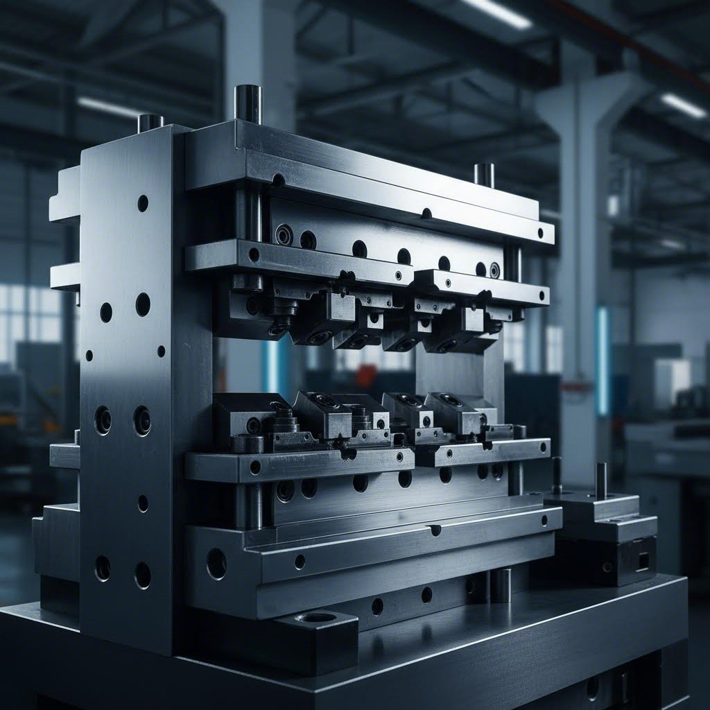
Βασικά Εξαρτήματα Συναρμολόγησης Μηχανικής Μήτρας
Τώρα που κατανοείτε τη λειτουργία μιας μηχανικής μήτρας, ας ρίξουμε μια ματιά στο εσωτερικό της. Μια συναρμολόγηση μήτρας μπορεί να φαίνεται απλή από το εξωτερικό, αλλά αν την ανοίξετε, θα διαπιστώσετε ότι πρόκειται για ένα ακριβώς μηχανολογικά σχεδιασμένο σύστημα, όπου κάθε εξάρτημα διαδραματίζει κρίσιμο ρόλο. Όταν οποιοδήποτε εξάρτημα αποτύχει ή φθαρεί πέραν των επιτρεπόμενων ορίων, ολόκληρη η γραμμή παραγωγής επηρεάζεται.
Η κατανόηση αυτών των εξαρτημάτων των μήτρων εκτύπωσης σας βοηθά να επικοινωνείτε πιο αποτελεσματικά με τους κατασκευαστές μητρών, να διαγνώσετε γρηγορότερα προβλήματα παραγωγής και να λαμβάνετε πιο ενημερωμένες αποφάσεις σχετικά με τους κύκλους συντήρησης και αντικατάστασης.
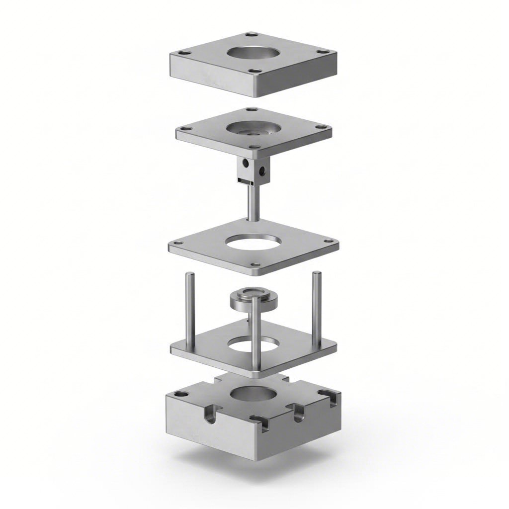
Ανατομία μιας ακριβούς συναρμολόγησης μήτρας
Φανταστείτε τη συναρμολόγηση μήτρας ως ένα σύνολο δύο κύριων κατηγοριών εξαρτημάτων: το δομικό πλαίσιο που συγκρατεί όλα τα υπόλοιπα εξαρτήματα και τα εργαζόμενα εξαρτήματα που μετασχηματίζουν πραγματικά το υλικό σας. Ας αναλύσουμε καθένα από αυτά.
Ο η μήτρα αποτελεί τη βάση — ουσιαστικά το σκελετό ολόκληρου του εργαλείου σας. Θα βρείτε τόσο την άνω όσο και την κάτω μήτρα-υπόστρωμα, δηλαδή δύο βαριές βάσεις που τοποθετούνται στον πρέσσο. Η κάτω μήτρα-υπόστρωμα στερεώνεται στο κρεβάτι του πρέσσο, ενώ η άνω μήτρα-υπόστρωμα συνδέεται με τον εμβολοφόρο άξονα (ram). Αυτές οι πλάκες πρέπει να είναι αρκετά σκληρές ώστε να αντιστέκονται σε παραμορφώσεις υπό τεράστιες δυνάμεις, που συχνά υπερβαίνουν τις εκατόνταδες τόνους.
Μεταξύ του πρέσσο και της μήτρας, οδηγών και φωτοκόλλητων διασφαλίζουν τέλεια στοίχιση κατά τη διάρκεια κάθε ενός μοναδικού κύκλου λειτουργίας. Σύμφωνα με την εταιρεία Moeller Precision Tool, κατασκευάζονται με ανοχές εντός των 0,0001 ιντσών — δηλαδή το ένα δέκατο του πάχους ενός ανθρώπινου τριχιού. Οι οδηγοί πείροι με σφαίρες έχουν καθιερωθεί ως βιομηχανικό πρότυπο, επειδή ολισθαίνουν ομαλά και διευκολύνουν τον διαχωρισμό των μήτρων κατά τη διάρκεια της συντήρησης.
Πλάκες υποστήριξης είναι ενισχυμένες πλάκες που τοποθετούνται πίσω από τα μύτη των πλακών κοπής και τις μήτρες. Ποια είναι η λειτουργία τους; Να κατανέμουν τις έντονες δυνάμεις που προκύπτουν κατά τη διάρκεια κάθε κύκλου λειτουργίας της πρέσας και να αποτρέπουν την παραμόρφωση του λιγότερο ανθεκτικού υλικού της βάσης της μήτρας με την πάροδο του χρόνου.
Ο τρόπος με τον οποίο κάθε εξάρτημα συνεισφέρει στην ποιότητα του εξαρτήματος
Ενεργά εξαρτήματα είναι εκείνα όπου πραγματοποιείται η πραγματική εργασία. Το κοντάρα είναι το αρσενικό εξάρτημα που εισχωρεί στο υλικό και εκτελεί την πραγματική εργασία κοπής ή διαμόρφωσης. Οι μύτες των πλακών κοπής διατίθενται σε διάφορα σχήματα — στρογγυλές, τετράγωνες, οβάλ ή προσαρμοστικά — ανάλογα με τη γεωμετρία που απαιτείται για το εξάρτημά σας. Η κεφαλή της μύτης της πλάκας κοπής συνδέεται με το σύστημα στήριξης που την ασφαλίζει στην άνω συνολική μήτρα.
Ο πλάκα εξαγωγής (ή κουμπί die) είναι ο θηλυκός αντίστοιχος του πάγκου. Παρέχει την αντίθετη ακμή κοπής και διαθέτει μια ακριβώς λειασμένη οπή που αντιστοιχεί στο προφίλ του πάγκου. Εδώ είναι που γίνεται ενδιαφέρον: το κουμπί die δεν είναι ακριβές αντίγραφο του πάγκου. Υπάρχει μια εσκεμμένη διακένηση, η οποία ονομάζεται διακένωση Μήτρας —συνήθως 5–10% του πάχους του υλικού ανά πλευρά.
Γιατί είναι τόσο σημαντική η διακένηση; Πολύ μικρή διακένηση προκαλεί υπερβολική φθορά τόσο στον πάγκο όσο και στο κουμπί die, αυξάνει την απαιτούμενη δύναμη και μπορεί να αφήσει τραχιές, σχισμένες ακμές στα εξαρτήματά σας. Πολύ μεγάλη διακένηση δημιουργεί ακμές (burrs), διαστασιακές ανακρίβειες και κακή ποιότητα ακμών. Η σωστή ρύθμιση αυτής της σχέσης είναι απαραίτητη για την επίτευξη καθαρών κοπών και μεγάλης διάρκειας ζωής των εργαλείων.
Ο πλάκα αποξέσεως επιλύει ένα πρακτικό πρόβλημα που ίσως δεν περιμένατε. Όταν ένας διαμορφωτής διαπερνά ελάσματα, η ελαστικότητα του υλικού τον κάνει να «σφίγγει» σφιχτά τον διαμορφωτή. Χωρίς αποκολλητήρα, το εξάρτημα θα μετακινούνταν προς τα πάνω μαζί με τον υποχωρούντα διαμορφωτή, προκαλώντας φράξιμο του καλουπιού και διακοπή της παραγωγής. Η πλάκα αποκολλητήρα αφαιρεί καθαρά αυτό το υλικό από τον διαμορφωτή, επιτρέποντας συνεχή λειτουργία.
| CompoNent | Λειτουργία | Τυπικά Υλικά |
|---|---|---|
| Υπόστρωμα μήτρας (άνω/κάτω) | Παρέχει δομική βάση· τοποθετείται στον τύπο | Χάλυβας, Κράματα Αλουμινίου |
| Οδηγοί Άξονες και Μανίκια | Διασφαλίζει ακριβή ευθυγράμμιση μεταξύ των δύο μισών του καλουπιού | Επεξεργασμένο εργαλειομηχανικό χάλυβα, ακριβώς λειασμένο |
| Πλάκες υποστήριξης | Κατανέμει τη δύναμη· προστατεύει τις βάσεις των καλουπιών από παραμόρφωση | Σκληρωμένο χάλυβα |
| Φορματικό | Αρσενικό κοπτικό/διαμορφωτικό εξάρτημα· μετασχηματίζει το υλικό | Εργαλειομηχανικός χάλυβας D2, A2, M2· καρβίδιο |
| Κουμπί καλουπιού / Πλάκα καλουπιού | Θηλυκή κοπτική άκρη· λειτουργεί σε συνεργασία με τον διαμορφωτή για τη δημιουργία εξαρτημάτων | D2, ενθέματα καρβιδίου |
| Πλάκα αποξέσεως | Αφαιρεί το υλικό από τον διαμορφωτή κατά την υποχώρησή του | Χάλυβας εργαλείων, επιλογές πολυουρεθάνης |
| Ελατήρια Μήτρας | Παρέχει δύναμη για τις λειτουργίες αφαίρεσης και προσαρμογής πίεσης | Σύρμα χρωμίου-σιλικονίου, κυλινδρικοί δοχείς αζώτου |
| Κρατήσεις μήτρας | Κρατάει σταθερά σε θέση τα μήτρωμα και τα κουμπιά | Ανθεκτικός σε όλο το πάχος κράμα χάλυβα |
Όταν αξιολογείτε ένα σύστημα πρέσας και μήτρας, θυμηθείτε ότι αυτά τα εξαρτήματα δεν λειτουργούν αυτόνομα. Οι καθοδηγητικοί πείροι πρέπει να συμπίπτουν τέλεια με τα βαθμωτά στρογγυλά εξαρτήματα (bushings). Το κενό μεταξύ μήτρωμα και κουμπιού πρέπει να ταιριάζει ακριβώς με το κουμπί της μήτρας. Το μηχάνημα αφαίρεσης (stripper) πρέπει να ενεργοποιείται ακριβώς την κατάλληλη στιγμή. Αυτή η διασυνδεδεμένη ακρίβεια είναι που διαχωρίζει μία υψηλής απόδοσης μήτρα από μία που πλήττεται από προβλήματα ποιότητας και υπερβολική αναστολή λειτουργίας.
Με αυτήν τη βάση στην ανατομία της μήτρας, είστε έτοιμοι να εξερευνήσετε τους διαφορετικούς τύπους μηχανικών μητρών και να ανακαλύψετε ποια διαμόρφωση ταιριάζει καλύτερα στις συγκεκριμένες απαιτήσεις παραγωγής σας.
Τύποι μηχανικών μητρών και εφαρμογές τους
Έχετε δει τι περιέχει ένα μηχανικό καλούπι. Τώρα έρχεται το μεγαλύτερο ερώτημα: ποιον τύπο καλουπιού πραγματικά χρειάζεστε; Η απάντηση εξαρτάται από τον όγκο παραγωγής σας, την πολυπλοκότητα των εξαρτημάτων και τους περιορισμούς του προϋπολογισμού σας. Η επιλογή λανθασμένου τύπου καλουπιού μπορεί να σημαίνει υπερβολική δαπάνη για εργαλειομηχανήματα σε απλά εξαρτήματα — ή δυσκολίες με προβλήματα ποιότητας όταν η εργαλειομηχανή σας δεν μπορεί να αντεπεξέλθει στην απαιτούμενη πολυπλοκότητα.
Ας αναλύσουμε τους κύριους τύπους καλουπιών σφράγισης (stamping dies) και να δούμε πότε ο καθένας είναι κατάλληλος για την παραγωγική σας διαδικασία.
Προοδευτικές Μήτρες για Υψηλή Παραγωγικότητα
Φανταστείτε ένα καλούπι σφράγισης που εκτελεί πολλαπλές εργασίες σε τέλεια ακολουθία, χωρίς ποτέ να αφήνει το εξάρτημα. Αυτό ακριβώς κάνει ένα προοδευτικό καλούπι (progressive die). Σύμφωνα με την Durex Inc., τα προοδευτικά καλούπια αποτελούνται από πολλαπλούς σταθμούς που διατάσσονται σε ακολουθία, με καθέναν να εκτελεί μια συγκεκριμένη εργασία καθώς το μεταλλικό φύλλο κινείται μέσω της πρέσας.
Ο τρόπος λειτουργίας του είναι ο εξής: μια ταινία ελάσματος τροφοδοτείται στο πρώτο σταθμό, όπου πραγματοποιείται η αρχική επεξεργασία—πιθανόν η διάτρηση ενός οδηγού οπών. Με κάθε κίνηση του πρεσαρίσματος, το υλικό προωθείται στον επόμενο σταθμό. Ο δεύτερος σταθμός μπορεί να πραγματοποιεί την αποκοπή του περιγράμματος. Ο τρίτος σταθμός διαμορφώνει μια πτέρυγα. Ο τέταρτος σταθμός προσθέτει ανάγλυφη επεξεργασία. Ο τελικός σταθμός αποχωρίζει το τελικό εξάρτημα από την ταινία φέρουσας βάσης.
Αυτή η προσέγγιση παρέχει εξαιρετική απόδοση για παραγωγή μεγάλων όγκων. Οι μεταλλικές μήτρες σφράγισης που διαμορφώνονται ως προοδευτικά συστήματα μπορούν να παράγουν πολύπλοκα εξαρτήματα με ταχύτητες που υπερβαίνουν τις 1.000 κινήσεις ανά λεπτό. Η αυτοκινητοβιομηχανία βασίζεται σε μεγάλο βαθμό σε αυτόν τον τύπο μητρών για την κατασκευή βραχιόνων στήριξης, συνδετήρων και δομικών εξαρτημάτων, όπου απαιτούνται ετησίως εκατομμύρια ταυτόσημα εξαρτήματα.
Κατάλληλο για:
- Παραγωγή μεγάλων όγκων (100.000+ εξαρτήματα)
- Εξαρτήματα που απαιτούν πολλαπλές επεξεργασίες (αποκοπή, διαμόρφωση, πλάστιγμα)
- Εξαρτήματα που παραμένουν συνδεδεμένα με την ταινία φέρουσας βάσης κατά τη διάρκεια της επεξεργασίας
- Εφαρμογές όπου το κόστος ανά εξάρτημα έχει μεγαλύτερη σημασία από την επένδυση στην κατασκευή των μητρών
Επιλογή Μεταξύ Σύνθετων και Μεταφορικών Λειτουργιών
Τι γίνεται αν χρειάζεστε την εκτέλεση πολλαπλών λειτουργιών ταυτόχρονα, αντί για διαδοχικά; Εκεί ακριβώς διακρίνονται οι σύνθετες μήτρες.
Μία σύνθετη μήτρα εκτελεί πολλαπλές κοπτικές λειτουργίες σε μία μόνο κίνηση. Φανταστείτε μία μήτρα που αποκόβει ένα σχήμα ενώ ταυτόχρονα διαμορφώνει εσωτερικές οπές — όλα αυτά σε έναν μόνο κύκλο λειτουργίας του πρεσαρίσματος. Αυτή η ενσωμάτωση μειώνει δραματικά τον χρόνο παραγωγής και διασφαλίζει τέλεια συγκέντρωση (alignment) μεταξύ των χαρακτηριστικών, καθώς όλα συμβαίνουν ταυτόχρονα.
Σύμφωνα με εμπειρογνώμονες κατασκευής της Worthy Hardware, το πρεσάρισμα με σύνθετη μήτρα προσφέρει εξαιρετική ακρίβεια και αποδοτική χρήση υλικού με ελάχιστα απόβλητα. Ωστόσο, υπάρχει ένας συμβιβασμός: αυτός ο τύπος μήτρας πρεσαρίσματος λειτουργεί καλύτερα για σχετικά επίπεδα εξαρτήματα με απλούστερες γεωμετρίες. Αν το εξάρτημά σας απαιτεί βαθιές διαμορφώσεις ή πολύπλοκη τρισδιάστατη διαμόρφωση, θα χρειαστείτε μία διαφορετική προσέγγιση.
Οι μήτρες μεταφοράς επιλύουν το πρόβλημα της πολυπλοκότητας μέσω μιας ουσιαστικά διαφορετικής στρατηγικής. Αντί να διατηρούν το εξάρτημα συνδεδεμένο με μια λωρίδα φέροντος, οι μήτρες μεταφοράς χρησιμοποιούν μηχανικά δάχτυλα ή ρομπότ για να μετακινούν φυσικά τα κομμάτια εργασίας μεταξύ ανεξάρτητων σταθμών. Κάθε σταθμός εκτελεί την αντίστοιχη εργασία του και στη συνέχεια απελευθερώνει το εξάρτημα για μεταφορά στον επόμενο.
Αυτή η ευελιξία καθιστά τις μήτρες μεταφοράς ιδανικές για:
- Μεγάλα εξαρτήματα που δεν χωρούν σε λωρίδα φέροντος προοδευτικής μήτρας
- Εξαρτήματα με βαθιά ελάσματα που απαιτούν πολλαπλά στάδια διαμόρφωσης
- Πολύπλοκες συναρμολογήσεις που απαιτούν εργασίες από διαφορετικές γωνίες
- Εξαρτήματα που απαιτούν αλλαγές προσανατολισμού κατά τη διάρκεια της επεξεργασίας
Το αντάλλαγμα; Η σφράγιση με μήτρες μεταφοράς συνεπάγεται συνήθως υψηλότερο κόστος λειτουργίας και μεγαλύτερους χρόνους προετοιμασίας. Θα χρειαστείτε επίσης εξειδικευμένους τεχνικούς για τη συντήρηση και τη λειτουργία. Ωστόσο, για πολύπλοκα εξαρτήματα αεροδιαστημικής τεχνολογίας ή εξαρτήματα βαριάς μηχανής, καμία άλλη μέθοδος δεν προσφέρει τον ίδιο συνδυασμό ακρίβειας και γεωμετρικής ευελιξίας.
Ειδικές κατηγορίες μητρών για συγκεκριμένες εργασίες
Πέρα από αυτές τις κύριες κατηγορίες, διάφορα ειδικά μήτρες σχηματισμού ανταποκρίνονται σε συγκεκριμένες ανάγκες παραγωγής:
- Μήτρες Διακοπής – Κόβουν συγκεκριμένα σχήματα από λαμαρίνα για τη δημιουργία επίπεδων ελασμάτων προς περαιτέρω επεξεργασία. Η απλή τους κατασκευή τις καθιστά οικονομικά αποδοτικές για την παραγωγή ελασμάτων με καθαρή κοπή και ελάχιστες απώλειες.
- Καλουπιών διαμόρφωσης – Διαμορφώνουν το υλικό σε τρισδιάστατα προφίλ μέσω λειτουργιών κάμψης, ανάδιπλωσης ή στροφής, χωρίς αφαίρεση υλικού. Είναι απαραίτητες για τη δημιουργία δομικών εξαρτημάτων με πολύπλοκα περιγράμματα.
- Σκίτσο αποθανών – Τραβούν τη λαμαρίνα σε βαθιές κοιλότητες για να δημιουργήσουν εξαρτήματα σε σχήμα κύπελλου ή κουτιού. Χρησιμοποιούνται συχνά στην κατασκευή σκευών μαγειρέματος, δοχείων αναψυκτικών και δεξαμενών καυσίμου αυτοκινήτων.
- Μήτρες Σφραγίσματος – Εφαρμόζουν εξαιρετικά υψηλή πίεση για τη δημιουργία επιφανειακών λεπτομερειών με υψηλή ακρίβεια και στενές οριακές τιμές διαστάσεων. Χρησιμοποιούνται εκτενώς στην κατασκευή κοσμημάτων και ιατρικών συσκευών.
- Τα καλούπια ανάγλυφης – Δημιουργούν ανάγλυφα ή εντυπώσεις για αισθητικούς και λειτουργικούς σκοπούς, όπως η βελτίωση της λαβής ή η προσθήκη στοιχείων εμπορικής επωνυμίας.
Ένα πλαίσιο λήψης αποφάσεων για την επιλογή μητρών
Ακούγεται περίπλοκο; Ακολουθεί μια πρακτική μέθοδος για τον περιορισμό των επιλογών σας:
| Παράγοντας Επιλογής | Προοδευτικός αποθανατικός | Συνδυασμένη περιτομή | Μήτρα μεταφοράς |
|---|---|---|---|
| Όγκος παραγωγής | Υψηλός (πάνω από 100.000 τεμάχια) | Χαμηλή έως μέτρια | Μεσαία έως υψηλή |
| Περιπλοκότητα Κομματιού | Μετριοπαθής | Απλό έως Μέτριο | Υψηλές |
| Μέγεθος εξαρτήματος | Μικρό έως Μεσαίο | Μικρό έως Μεσαίο | Μεσαίο έως Μεγάλο |
| Αρχικό κόστος εργαλείων | Υψηλές | Μετριοπαθής | Υψηλές |
| Κόστος Ανά Εξάρτημα | Χαμηλά | Μετριοπαθής | Μέτρια προς Υψηλή |
| Χρόνος μετασκευής | Μετριοπαθής | Χαμηλά | Υψηλές |
Όταν καθορίζετε τα μήτρες ελάσματος για το έργο σας, ξεκινήστε με τρεις ερωτήσεις: Πόσα τεμάχια χρειάζεστε ετησίως; Πόσο περίπλοκη είναι η γεωμετρία; Ποιός είναι ο προϋπολογισμός σας για την κατασκευή των μητρών σε σύγκριση με το κόστος ανά τεμάχιο;
Για αυτοκινητοβιομηχανικά εξαρτήματα υψηλού όγκου, οι προοδευτικές μήτρες παρέχουν συνήθως το χαμηλότερο συνολικό κόστος. Για ακριβή ιατρικά εξαρτήματα σε μικρότερες ποσότητες, οι σύνθετες μήτρες είναι συχνά πιο λογική επιλογή. Για μεγάλες αεροδιαστημικές επιφάνειες με περίπλοκες απαιτήσεις διαμόρφωσης, οι μήτρες μεταφοράς προσφέρουν δυνατότητες που απλούστερα συστήματα δεν μπορούν να αντιστοιχήσουν.
Η κατανόηση αυτών των τύπων μητρών σας επιτρέπει να διεξάγετε αποτελεσματικές συζητήσεις με τους κατασκευαστές μητρών και να καθορίζετε προδιαγραφές που συμβαδίζουν με τις πραγματικότητες της παραγωγής σας. Ωστόσο, η επιλογή του κατάλληλου τύπου μήτρας αποτελεί μόνο ένα μέρος της εξίσωσης· τα υλικά που χρησιμοποιούνται για την κατασκευή των μητρών έχουν εξίσου σημαντική επίδραση στην απόδοση, τη διάρκεια ζωής και το συνολικό κόστος κατοχής.
Τα Υλικά και οι Επιφανειακές Επεξεργασίες για Βέλτιστη Απόδοση
Έχετε επιλέξει τον κατάλληλο τύπο μήτρας για την εφαρμογή σας. Τώρα έρχεται μια απόφαση που θα καθορίσει πόσο θα διαρκέσει αυτή η εργαλειοθήκη και πόσα εξαιρετικής ποιότητας εξαρτήματα θα παράγει: η επιλογή του υλικού. Η λανθασμένη επιλογή χάλυβα μήτρας μπορεί να οδηγήσει σε πρόωρη αποτυχία, υπερβολικά έξοδα συντήρησης και προβλήματα ποιότητας που επηρεάζουν ολόκληρη τη διαδικασία παραγωγής σας.
Είτε πραγματοποιείτε κοπή μαλακών αλουμινίου βραχιόνων είτε διαπερνάτε σκληρυμένο χάλυβα, τα υλικά που χρησιμοποιούνται στις μήτρες επεξεργασίας ελάσματος επηρεάζουν άμεσα την απόδοση, τη διάρκεια ζωής και το συνολικό κόστος κατοχής. Ας εξερευνήσουμε τι καθιστά μοναδική κάθε επιλογή.
Βαθμοί Χάλυβα Εργαλείων και Χαρακτηριστικά Απόδοσής τους
Οι χάλυβες εργαλείων αποτελούν τη βάση της κατασκευής της πλειονότητας των μεταλλικών καλουπιών. Σύμφωνα με την Ryerson, οι χάλυβες εργαλείων περιέχουν από 0,5% έως 1,5% άνθρακα, καθώς και καρβίδια που σχηματίζονται από τέσσερα κύρια στοιχεία κραμάτωσης: βολφράμιο, χρώμιο, βανάδιο και μολυβδένιο. Τα στοιχεία αυτά προσδίδουν στον χάλυβα καλουπιών εξαιρετική σκληρότητα, αντοχή στη φθορά και ικανότητα διατήρησης της ακμής κοπής υπό ακραίες πιέσεις.
Ωστόσο, αυτό που πολλοί αγοραστές παραβλέπουν είναι ότι όχι όλοι οι χάλυβες εργαλείων παρουσιάζουν ίση απόδοση σε διαφορετικές εφαρμογές. Η κατηγορία που επιλέγετε πρέπει να αντιστοιχεί στις συγκεκριμένες απαιτήσεις της παραγωγής σας.
Εργαλειοχάλυβας D2 ο χάλυβας D2 αποτελεί τον «εργάτη» των καλουπιών σφυρηλάτησης χάλυβα. Με το υψηλό περιεχόμενο άνθρακα και χρωμίου, ο D2 επιτυγχάνει σκληρότητα 62–64 HRC μετά τη θερμική κατεργασία. Αυτά τα σκληρά σωματίδια καρβιδίου παρέχουν εξαιρετική αντοχή στην απόσβεση — ιδανική για καλούπια αποκοπής, διατρήσεως και διαμόρφωσης που απαιτούν αυστηρές ανοχές κατά τη διάρκεια εκτεταμένων παραγωγικών κύκλων. Εάν παράγετε εκατοντάδες χιλιάδες εξαρτήματα από το ίδιο καλούπι, η αντοχή του D2 στη φθορά δικαιολογεί συχνά το κόστος του.
Εργαλειοθηκών Χάλυβας A2 προσφέρει εξαιρετική ισορροπία όταν απαιτείται ταυτόχρονα αντοχή και αντοχή στη φθορά. Το περιεχόμενό του σε χρώμιο (5%) παρέχει υψηλή σκληρότητα (63–65 HRC σε κατάσταση όπως εξανθρακώθηκε), διατηρώντας παράλληλα τη διαστασιακή σταθερότητα κατά τη θερμική κατεργασία. Αυτό καθιστά τον χάλυβα A2 ιδιαίτερα πολύτιμο για μήτρες κοπής, μήτρες διαμόρφωσης και εφαρμογές χύτευσης με έγχυση, όπου η ακρίβεια έχει την ίδια σημασία με την αντοχή.
Χάλυβας εργαλείου S7 ακολουθεί εντελώς διαφορετική προσέγγιση. Ως βαθμίδα ανθεκτική στην κρούση, ο χάλυβας S7 δίνει προτεραιότητα στην αντοχή σε κρούση έναντι της απλής σκληρότητας. Επιτυγχάνει σκληρότητα 60–62 HRC κατά την εξανθράκωση, αλλά η πραγματική του δύναμη έγκειται στην ικανότητά του να απορροφά επανειλημμένα μηχανικά κρούσματα χωρίς να παρουσιάζει ρωγμές ή θραύσματα. Όταν οι μήτρες εργαλείων σας υφίστανται εφαρμογές υψηλής κρούσης — όπως σε σφυριές, μήτρες κοπής για παχύτερα υλικά ή μήτρες καρφωτών — ο χάλυβας S7 συχνά υπερτερεί από σκληρότερες, αλλά πιο εύθραυστες εναλλακτικές λύσεις.
| Βαθμός Χάλυβα Εργαλείου | Σκληρότητα (HRC) | Κύριες ιδιότητες | Καλύτερες Εφαρμογές | Σχετικό Κόστος |
|---|---|---|---|---|
| D2 | 62-64 | Εξαιρετική αντοχή στη φθορά, υψηλή περιεκτικότητα σε χρώμιο | Μήτρες κοπής για μεγάλες παραγωγικές σειρές, κοπή, μήτρες διαμόρφωσης | Μετριοπαθής |
| A2 | 63-65 | Ισορροπημένη αντοχή και αντοχή στη φθορά, διαστασιακή σταθερότητα | Μήτρες κοπής, μήτρες περικοπής, εργαλεία διαμόρφωσης | Μετριοπαθής |
| S7 | 60-62 | Υψηλή αντοχή σε κρούσεις, εξαιρετική ταμπερατότητα | Εργαλεία υψηλής φόρτισης: διαμορφωτικά, σφυρίσματα, εφαρμογές κρούσης | Μετριοπαθής |
| O1 | 57-62 | Εύκολη κατεργασία, καλή διατήρηση ακμής | Λεπίδες διατομής, εργαλεία κοπής γενικής χρήσης | Χαμηλά |
| M2 | 62-64 | Διατήρηση σκληρότητας σε υψηλές θερμοκρασίες | Εργαλεία υψηλής ταχύτητας κοπής, μύτες, κοχλίες | Υψηλότερη |
Όταν οι καρβιδικές ενθέσεις δικαιολογούν την επένδυση
Μερικές φορές ακόμα και τα προνομιούχα χάλυβες εργαλείων δεν μπορούν να προσφέρουν τη διάρκεια ζωής που απαιτεί η παραγωγή σας. Εκεί εμφανίζονται οι καρβιδικές ενθέσεις.
Το καρβίδιο του βολφραμίου είναι εξαιρετικά σκληρό — σημαντικά πιο σκληρό από οποιοδήποτε χάλυβα εργαλείων. Σύμφωνα με την Alsette, οι μήτρες με καρβιδικές ενθέσεις χρησιμοποιούν αυτά τα εξαιρετικά σκληρά κομμάτια, τα οποία ενσωματώνονται σε περιοχές υψηλής φθοράς του σώματος της μήτρας από χάλυβα. Αντί να κατασκευάζεται ολόκληρη μήτρα ελάσματος από καρβίδιο (κάτι που θα ήταν απαγορευτικά ακριβό και εύθραυστο), οι κατασκευαστές τοποθετούν στρατηγικά τις ενθέσεις στις ακμές κοπής, στα διαμορφωτικά, στις ακτίνες καμπύλων τραβήγματος και στις επιφάνειες διαμόρφωσης.
Αυτή η υβριδική προσέγγιση προσφέρει εντυπωσιακά πλεονεκτήματα:
- Επεκταμένη διάρκεια ζωής των μήτρων – Οι ενσωματώσεις καρβιδίου μπορούν να διαρκούν 5–10 φορές περισσότερο από τα εξαρτήματα από χάλυβα εργαλείων σε εφαρμογές με υψηλή απόσβηση
- Μειωμένες Δαπάνες Αντικατάστασης – Όταν παρουσιαστεί φθορά, αντικαθιστάτε μόνο την ενσωμάτωση και όχι ολόκληρο το εξάρτημα της μήτρας
- Ελαχιστοποιημένος Χρόνος Αδράνειας – Οι ταχύτερες αντικαταστάσεις ενσωματώσεων σημαίνουν λιγότερες διακοπές της παραγωγής
- Σταθερή Ποιότητα Εξαρτημάτων – Το καρβίδιο διατηρεί για μεγαλύτερο χρονικό διάστημα τις οξείες ακμές του, παράγοντας καθαρότερες κοπές σε όλη τη διάρκεια της παραγωγής
Πότε δικαιολογείται η υψηλότερη αρχική δαπάνη του καρβιδίου; Λάβετε το υπόψη σας για παραγωγή μεγάλου όγκου που υπερβαίνει το ένα εκατομμύριο τεμάχια, κατά την εναπόθεση αποβλητικών ή ενισχυμένων υλικών, ή όταν οι κρίσιμες ακμές κοπής καθορίζουν την ποιότητα του τελικού προϊόντος. Οι κατασκευαστές αυτοκινήτων που παράγουν μικρούς ακροδέκτες, συνδέσμους και συνδετήρες καθορίζουν συστηματικά ενσωματώσεις καρβιδίου, διότι ο μεγάλος όγκος παραγωγής καθιστά την επένδυση αποδοτική σε σύντομο χρονικό διάστημα.
Επιφανειακές Επεξεργασίες που Επεκτείνουν τη Διάρκεια Ζωής των Καλουπιών
Πέρα από την επιλογή του βασικού υλικού, οι επιφανειακές μεταχειρίσεις και οι επιστρώσεις μπορούν να βελτιώσουν δραματικά την απόδοση των μεταλλικών καλουπιών σας. Αυτές οι εφαρμογές λεπτών φιλμ προσθέτουν προστατευτικά στρώματα που μειώνουν την τριβή, αντιστέκονται στη φθορά και εμποδίζουν την πρόσφυση — χωρίς να αλλάζουν τις βασικές ιδιότητες του εργαλείου.
TiN (Νιτρίδιο Τιτανίου) οι επιστρώσεις TiN δημιουργούν μια ξεχωριστή επιφάνεια χρυσού χρώματος με σκληρότητα περίπου 2.300 HV. Αυτή η επίστρωση μειώνει την τριβή μεταξύ του καλουπιού και του εξαρτήματος, επεκτείνει τη διάρκεια ζωής του εργαλείου κατά 2–4 φορές σε πολλές εφαρμογές και βοηθά στην πρόληψη συσσώρευσης υλικού στις ακμές κοπής.
TiCN (Τιτάνιο Καρβονιτρίδιο) οι επιστρώσεις TiCN βασίζονται στην τεχνολογία του TiN, προσφέροντας ακόμη μεγαλύτερη σκληρότητα (περίπου 3.000 HV) και βελτιωμένη αντοχή στη φθορά. Η μπλε-γκρι εμφάνισή τους υποδηλώνει ανώτερη απόδοση σε εφαρμογές διαπεράσματος και διαμόρφωσης σκληρότερων υλικών, όπως το ανοξείδωτο χάλυβα.
DLC (Άνθρακας Ομοιάζων με Διαμάντι) οι επιστρώσεις DLC επιτυγχάνουν εξαιρετικά επίπεδα σκληρότητας που πλησιάζουν αυτά του διαμαντιού, διατηρώντας παράλληλα εξαιρετικά χαμηλούς συντελεστές τριβής. Το DLC διακρίνεται σε εφαρμογές που περιλαμβάνουν αλουμίνιο και άλλα υλικά που τείνουν να προσκολλώνται ή να παρουσιάζουν φαινόμενο πρόσφυσης (galling).
Η επιλογή του κατάλληλου συνδυασμού βασικού υλικού και επιφανειακής επεξεργασίας απαιτεί την εξισορρόπηση διαφόρων παραγόντων: τη σκληρότητα και την αποξεστικότητα του υλικού του τεμαχίου εργασίας, το αναμενόμενο όγκο παραγωγής, τις απαιτήσεις για ανοχές και τους περιορισμούς του προϋπολογισμού. Ένας κατασκευαστής μήτρας με εμπεριστατωμένη εμπειρία στον τομέα εφαρμογής σας μπορεί να σας καθοδηγήσει σε αυτήν την απόφαση — κάτι που μας οδηγεί στη μηχανική διαδικασία που μετατρέπει τις προδιαγραφές υλικού σε εργαλεία έτοιμα για παραγωγή.
Η Διαδικασία Σχεδιασμού Μήτρας: Από την Ιδέα έως την Παραγωγή
Έχετε επιλέξει τον κατάλληλο τύπο μήτρας και έχετε καθορίσει τα κατάλληλα υλικά. Τώρα ακολουθεί η φάση της μηχανικής σχεδίασης, κατά την οποία αυτές οι αποφάσεις μετατρέπονται σε ένα φυσικό εργαλείο ικανό να παράγει εκατομμύρια ακριβή εξαρτήματα. Τι είναι, στην ουσία, η κατασκευή μήτρας; Είναι μια πειθαρχημένη μηχανική διαδικασία που κλείνει το κενό μεταξύ του σχεδιασμού του εξαρτήματός σας και μιας μήτρας σφράγισης έτοιμης για παραγωγή.
Η κατανόηση αυτού του δρόμου σας βοηθά να ορίσετε ρεαλιστικούς χρονοδιαγράμματα, να θέτετε καλύτερες ερωτήσεις κατά τη διάρκεια των επισκοπήσεων σχεδιασμού και να αναγνωρίζετε πότε οι μηχανικές συντομεύσεις ενδέχεται να θέσουν σε κίνδυνο τα αποτελέσματά σας στο μέλλον.
Μηχανικές πτυχές που καθορίζουν την επιτυχία του καλουπιού
Κάθε επιτυχημένο σχέδιο καλουπιού εμβολοθλάσεως ξεκινά με μια εξονυχιστική ανάλυση του ίδιου του εξαρτήματος. Σύμφωνα με Εργαλείο Dramco , η κατανόηση του σκοπού του σχεδιασμού του εξαρτήματος — δηλαδή πώς θα χρησιμοποιηθεί και πώς πρέπει να λειτουργεί στην πραγματικότητα — παρέχει κρίσιμες ενδείξεις για τις απαιτήσεις των χαρακτηριστικών του και δημιουργεί ευκαιρίες για βελτιστοποίηση του σχεδιασμού προκειμένου να διευκολυνθεί η κατασκευή.
Πριν από την έναρξη οποιασδήποτε μοντελοποίησης CAD, οι έμπειροι μηχανικοί καλουπιών αξιολογούν αρκετούς κρίσιμους παράγοντες:
- Η υλική συμπεριφορά – Πώς θα ρέει το λαμαρίνιο κατά τη διαδικασία σχηματοποίησης; Τι ποσό ελαστικής επαναφοράς (springback) μπορείτε να περιμένετε μετά τις λειτουργίες κάμψης;
- Κρίσιμες Ανοχές – Ποιες διαστάσεις είναι πιο σημαντικές για τη λειτουργία του εξαρτήματος και την εφαρμογή του στη συναρμολόγηση;
- Όγκος παραγωγής – Πώς επηρεάζει ο αναμενόμενος όγκος παραγωγής τις αποφάσεις σχετικά με την πολυπλοκότητα του καλουπιού και την επιλογή των υλικών;
- Συμβατότητα με τον τύπο πρέσας – Ποιοι περιορισμοί εξοπλισμού επηρεάζουν το μέγεθος του καλουπιού, το μήκος της διαδρομής και τις απαιτήσεις τόνων;
Εδώ είναι όπου πολλά έργα αποτυγχάνουν: οι υποθέσεις αντικαθιστούν την προσεκτική ανάλυση. Όπως τονίζουν οι εμπειρογνώμονες του κλάδου, η αποφυγή υποθέσεων και η θέση διευκρινιστικών ερωτήσεων όταν λείπουν πληροφορίες προλαμβάνει ακριβά επανασχεδιασμούς σε μεταγενέστερο στάδιο. Ένα σχέδιο καλουπιού για μεταλλική εμβολοθλάση που βασίζεται σε ατελείς προδιαγραφές θα απαιτήσει ακριβές τροποποιήσεις μόλις η παραγωγή αποκαλύψει τα κενά.
Η καθιέρωση των ανοχών αξίζει ιδιαίτερης προσοχής κατά τη διάρκεια αυτής της φάσης. Στη σύγχρονη παραγωγή, οι ανοχές έχουν γίνει όλο και πιο αυστηρές — συχνά μια μικρή κλάσμα της ίντσας. Το εργαλείο καλουπιού σας πρέπει να λαμβάνει υπόψη τη συσσωρευτική μεταβλητότητα που προκαλείται από τις διακυμάνσεις του πάχους του υλικού, την παραμόρφωση της πρέσας, τη θερμική διαστολή και τη σταδιακή φθορά του εργαλείου. Η διαδικασία σχεδιασμού του καλουπιού εμβολοθλάσης μεταφράζει τις προδιαγραφές του τελικού εξαρτήματος σε αντίστροφη σειρά, προκειμένου να καθοριστούν οι διαστάσεις του εργαλείου που απαιτούνται για την επαναλαμβανόμενη επίτευξη αυτών των προδιαγραφών.
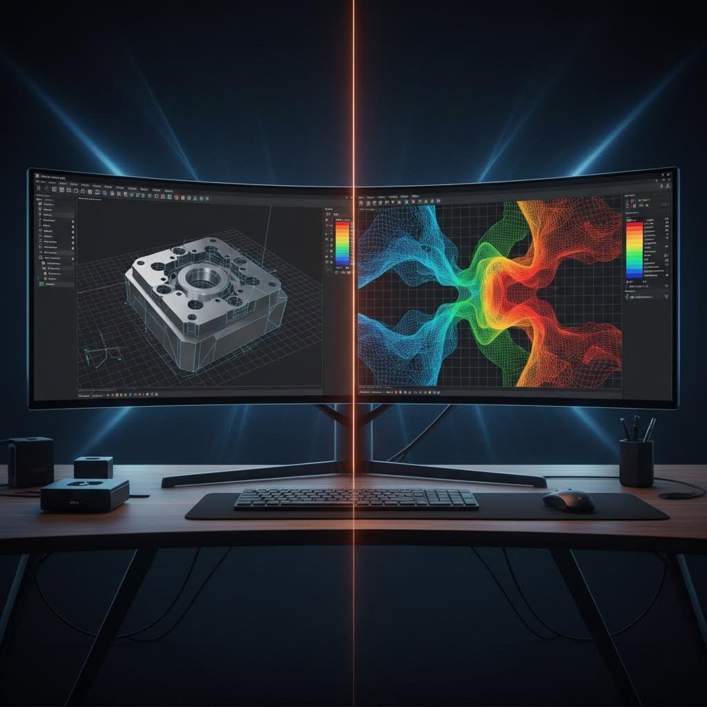
Από το Ψηφιακό Σχέδιο στη Φυσική Ακρίβεια
Η σύγχρονη σχεδίαση και ανάπτυξη μήτρας βασίζεται σε μεγάλο βαθμό σε λογισμικό σχεδίασης με υποστήριξη υπολογιστή (CAD). Οι μηχανικοί δημιουργούν λεπτομερή τρισδιάστατα μοντέλα κάθε συστατικού της μήτρας — διαμορφωτικών πινσέτων, κουμπιών μήτρας, αποσπαστικών, συστημάτων καθοδήγησης — και επαληθεύουν την αλληλεπίδρασή τους μέσω ψηφιακής συναρμολόγησης. Αυτό το εικονικό περιβάλλον επιτρέπει στους σχεδιαστές να εντοπίζουν προβλήματα σύγκρουσης, να βελτιστοποιούν τις διαδρομές ροής του υλικού και να διαμορφώνουν με ακρίβεια τα κενά πριν από την κοπή οποιουδήποτε χάλυβα.
Ωστόσο, η μόνη χρήση λογισμικού CAD δεν εγγυάται την επιτυχία. Εδώ είναι που η προσομοίωση CAE (Μηχανική με υποστήριξη υπολογιστή) μεταμορφώνει τη διαδικασία κατασκευής μήτρας.
Σύμφωνα με Keysight Technologies , το λογισμικό προσομοίωσης διαμόρφωσης ελάσματος επιτρέπει εικονικές δοκιμές μήτρας που εντοπίζουν πιθανά ελαττώματα πριν από την κατασκευή των φυσικών εργαλείων. Αυτές οι προσομοιώσεις προβλέπουν:
- Πρότυπα Ροής Υλικού – Τον τρόπο με τον οποίο κινείται και εκτείνεται το έλασμα κατά τις εργασίες διαμόρφωσης
- Το μέγεθος της ελαστικής ανάκαμψης (springback) – Ιδιαίτερα κρίσιμο για προηγμένα υλικά υψηλής αντοχής και κράματα αλουμινίου, τα οποία είναι δύσκολο να διαμορφωθούν
- Πιθανή λεπταίνση ή ρήξη – Περιοχές όπου το υλικό ενδέχεται να αποτύχει υπό τις τάσεις διαμόρφωσης
- Κίνδυνοι ρυτίδωσης – Ζώνες συμπίεσης που ενδέχεται να προκαλέσουν επιφανειακές ατέλειες
Γιατί αυτό έχει σημασία για τον προϋπολογισμό σας; Οι ελλείψεις στο σχέδιο του εξαρτήματος και της διαδικασίας εμφανίζονται συχνά μόνο κατά τις πρώτες δοκιμές στο στάδιο δοκιμής (try-out) κατά την κατασκευή των μήτρων—όταν οι διορθώσεις είναι τόσο χρονοβόρες όσο και δαπανηρές. Η προσομοίωση ανιχνεύει αυτά τα προβλήματα ψηφιακά, όταν οι αλλαγές κοστίζουν ώρες μηχανικού χρόνου αντί για εβδομάδες τροποποίησης των εργαλείων.
Η διαδικασία προσομοίωσης βοηθά επίσης στη βελτιστοποίηση των ρυθμίσεων της πρεσσών. Η επίτευξη ιδανικών συνθηκών κοπής απαιτεί ακριβή ρύθμιση παραμέτρων όπως η ταχύτητα της πρεσσών, η δύναμη του συγκρατητή ελάσματος και η λίπανση. Οι εικονικές δοκιμές μειώνουν σημαντικά τη φυσική δοκιμή και σφάλμα που παραδοσιακά απαιτείτο, συντομεύοντας το χρόνο μέχρι την παραγωγή.
Ανάπτυξη και επικύρωση πρωτοτύπου
Ακόμα και με εξελημένες προσομοιώσεις, η φυσική επαλήθευση παραμένει απαραίτητη. Τα πρωτότυπα καλούπια — που ονομάζονται ενίοτε «μαλακά» καλούπια — επιτρέπουν στους μηχανικούς να επαληθεύσουν τις ψηφιακές τους προβλέψεις με βάση την πραγματική συμπεριφορά των υλικών. Αυτά τα πρωτότυπα χρησιμοποιούν συνήθως φθηνότερα υλικά και απλοποιημένη κατασκευή, επιτρέποντας ταχύτερη επανάληψη πριν από την επένδυση σε καλούπια παραγωγικού επιπέδου.
Κατά τη διάρκεια των δοκιμών επαλήθευσης, οι μηχανικοί μετρούν:
- Τη διαστασιακή ακρίβεια σε όλα τα κρίσιμα χαρακτηριστικά
- Την ποιότητα της κατάστασης των ακμών και το ύψος των ακμών (burr)
- Την επιφανειακή απόδοση στις διαμορφωμένες περιοχές
- Τη λεπταίνση του υλικού στις ακτίνες διαμόρφωσης (draw radii)
- Την αποτελεσματικότητα της αντιστάθμισης της ελαστικής επαναφοράς (springback)
Αυτά τα δεδομένα επανατροφοδοτούν τη διαδικασία σχεδιασμού, βελτιώνοντας το καλούπι για την παραγωγή σε βιομηχανική κλίμακα. Κατά το σχεδιασμό ενός καλουπιού για την παραγωγή πολύπλοκων αυτοκινητοβιομηχανικών ή αεροδιαστημικών εξαρτημάτων, ενδέχεται να απαιτηθούν πολλαπλές επαναλήψεις πρωτοτύπων για την επίτευξη της απαιτούμενης ακρίβειας.
Σε όλη αυτή τη διαδρομή, η τεκμηρίωση έχει εξαιρετική σημασία. Οι λεπτομερείς σχεδιαγραφές των καλουπιών καταγράφουν κάθε διάσταση, ανοχή και προδιαγραφή υλικού. Αυτά τα αρχεία υποστηρίζουν τη μελλοντική συντήρηση, την αντικατάσταση εξαρτημάτων και πιθανές τροποποιήσεις του σχεδιασμού καθώς εξελίσσεται το προϊόν σας.
Η μηχανική επένδυση που πραγματοποιείτε κατά τη φάση σχεδιασμού αποδίδει καρπούς σε όλη τη διάρκεια ζωής παραγωγής του καλουπιού σας. Ένα καλά μηχανικά σχεδιασμένο εργαλείο παράγει ενιαία εξαρτήματα με ελάχιστες ρυθμίσεις, ενώ ένα βιαστικός σχεδιασμός δημιουργεί συνεχείς δυσκολίες που καταναλώνουν ώρες συντήρησης και παράγουν απόβλητα. Μόλις επικυρωθεί ο σχεδιασμός σας, η επόμενη πρόκληση είναι η μετάφραση αυτών των προδιαγραφών σε ακριβώς κατασκευασμένα εξαρτήματα καλουπιού.
Μέθοδοι Κατασκευής και Πρότυπα Ακρίβειας
Ο σχεδιασμός της μήτρας σας ολοκληρώθηκε και επικυρώθηκε. Έρχεται τώρα η στιγμή της αλήθειας: η μετατροπή αυτών των ψηφιακών προδιαγραφών σε φυσική μηχανική εξοπλισμένη ικανή να παράγει εκατομμύρια ακριβείς εξαρτήσεις. Η διαδικασία κατεργασίας της μήτρας καθορίζει εάν ο προσεκτικά μηχανολογημένος σχεδιασμός σας μεταφράζεται σε μια μήτρα που λειτουργεί άριστα ή σε μια μήτρα που πλήττεται από διαστασιακά προβλήματα και πρόωρη φθορά.
Η κατανόηση του τρόπου κατασκευής των μητρών σας βοηθά να αξιολογήσετε τις δυνατότητες των προμηθευτών, να θέσετε ρεαλιστικές προσδοκίες για την παράδοση και να αναγνωρίσετε τους δείκτες ποιότητας που διαχωρίζουν την εξοπλισμένη μηχανική παγκόσμιας κλάσης από τις μεσοπρόθεσμες εναλλακτικές λύσεις.
Μέθοδοι Ακριβούς Κατεργασίας για την Κατασκευή Μητρών
Η κατασκευή εξοπλισμένης μηχανικής στα επίπεδα ακρίβειας που απαιτούνται για τη σύγχρονη κοπή απαιτεί μια προσεκτικά συντονισμένη ακολουθία κατεργασιών. Κάθε μέθοδος ανταποκρίνεται σε συγκεκριμένες απαιτήσεις, και οι εμπειρογνώμονες κατασκευαστές μητρών γνωρίζουν ακριβώς πότε πρέπει να εφαρμόσουν κάθε τεχνική.
Μηχανική με CNC αποτελεί τη βάση για την κατασκευή της πλειονότητας των μήτρων. Σύμφωνα με την Ohio Valley Manufacturing, αυτή η ευέλικτη τεχνική χρησιμοποιεί μηχανήματα ελεγχόμενα από υπολογιστή για την ακριβή αφαίρεση υλικού σύμφωνα με προγραμματισμένες οδηγίες. Οι λειτουργίες CNC φρεζαρίσματος και τόρνευσης δημιουργούν τη βασική γεωμετρία της μήτρας, καθορίζοντας τα κύρια χαρακτηριστικά εντός ανοχών ±0,001 έως ±0,005 ιντσών.
Οι πολυάξονες δυνατότητες CNC — συμπεριλαμβανομένης της 5-άξονας και 6-άξονας κατεργασίας — επιτρέπουν την ταυτόχρονη κοπή από πολλές κατευθύνσεις σε μία μόνο ρύθμιση. Αυτό έχει σημασία, διότι κάθε φορά που επανατοποθετείτε ένα τεμάχιο εργασίας, εισάγετε δυνητικά σφάλματα στον προσανατολισμό. Η μείωση των ρυθμίσεων σημαίνει αυστηρότερες ανοχές και ταχύτερη παραγωγή.
ΗΕΔ (κατεργασία με ηλεκτρική εκκένωση) αντιμετωπίζει γεωμετρίες που οι συμβατικές κοπτικές εργαλειομηχανές απλώς δεν μπορούν να επιτύχουν. Αυτή η διαδικασία λειτουργεί με τη δημιουργία ελεγχόμενων ηλεκτρικών σπινθήρων μεταξύ ενός ηλεκτροδίου και του τεμαχίου εργασίας, προκαλώντας την εξάλειψη του υλικού σε εξαιρετικά ακριβείς μονάδες. Δύο βασικές μέθοδοι EDM χρησιμοποιούνται για διαφορετικούς σκοπούς στην κατεργασία μητρών:
- Σύρμα EDM χρησιμοποιεί μια συνεχώς κινούμενη λεπτή σύρμα (συνήθως διαμέτρου 0.004–0.012 ιντσών) για την κοπή περίπλοκων προφίλ και ενδιαφέροντων σχημάτων. Διακρίνεται στη δημιουργία ακριβών προφίλ κοπτικών και μήτρας, τα οποία καθορίζουν τη γεωμετρία του εξαρτήματός σας, επιτυγχάνοντας ανοχές εντός ±0,0001 ιντσών.
- Σινκερ ΕΝΜ χρησιμοποιεί έναν διαμορφωμένο ηλεκτροδίο που «βυθίζεται» στο τεμάχιο εργασίας, δημιουργώντας κοιλότητες και περίπλοκα τρισδιάστατα χαρακτηριστικά. Αυτή η μέθοδος παράγει τις ενδιαφέρουσες λεπτομέρειες και τις οξείες εσωτερικές γωνίες που είναι αδύνατο να επιτευχθούν με περιστρεφόμενα κοπτικά εργαλεία.
Σύμφωνα με ειδικούς της βιομηχανίας από την Actco Tool, η μέθοδος EDM είναι ιδιαίτερα κατάλληλη για την παραγωγή περίπλοκων σχημάτων, οξειών γωνιών και λεπτομερών χαρακτηριστικών, τα οποία μπορεί να είναι δύσκολο να επιτευχθούν με συμβατικές μεθόδους κατεργασίας.
Λατομεία παρέχει την τελική διαστασιακή ακρίβεια και την επιθυμητή επιφανειακή απόδοση που απαιτούνται για τα εξαρτήματα της μήτρας σας. Η ακριβής κοπή μήτρας απαιτεί επιφανειακές αποδόσεις που μετρώνται σε μικροίντσες, και η λείανση επιτυγχάνει αυτό μέσω αφαίρεσης υλικού με αποξεστικό τρόπο. Η επίπεδη λείανση δημιουργεί επίπεδες και παράλληλες επιφάνειες στις βάσεις και τις πλάκες υποστήριξης της μήτρας. Η κυλινδρική λείανση παράγει κυκλικά χαρακτηριστικά, όπως οι οδηγοί πείροι, σύμφωνα με αυστηρές προδιαγραφές. Η προφιλική λείανση βελτιώνει πολύπλοκα περιγράμματα σε μήτρες κοπής (punches) και τμήματα μήτρας.
Χειροκίνητη κατεργασία μπορεί να φαίνεται παρωχημένη σε μια εποχή υπολογιστικά ελεγχόμενης ακρίβειας, αλλά οι εμπειρογνώμονες κατασκευαστές μητρών εξακολουθούν να εκτελούν κρίσιμες τελικές ρυθμίσεις. Οι εργασίες τριβής με λίθο, λείανσης (lapping) και πολύρανσης αφαιρούν τα μικροσκοπικά σημάδια εργαλείου που απομένουν από τη μηχανική κατεργασία, δημιουργώντας επιφάνειες με επίπεδο καθρέφτη που εμποδίζουν την πρόσφυση και την επιφανειακή φθορά (galling) του υλικού κατά την παραγωγή.
Η Ακολουθία Κατασκευής
Η μηχανική κατεργασία μιας ακριβούς μήτρας ακολουθεί μια λογική σειρά από το ακατέργαστο υλικό μέχρι το τελικό εξάρτημα:
- Προκαταρκτική Κατεργασία – Η φρεζάρισμα με CNC αφαιρεί το μεγαλύτερο μέρος του υλικού, αφήνοντας 0,010–0,020 ίντσες για τις επόμενες εργασίες
- Θερμική Επεξεργασία – Τα εξαρτήματα εξανθρακώνονται για να επιτευχθεί η απαιτούμενη σκληρότητα και αντοχή στη φθορά
- Μεσαία κατεργασία – Οι εργασίες μετά τη θερμική κατεργασία διορθώνουν οποιαδήποτε παραμόρφωση και προσεγγίζουν τις τελικές διαστάσεις
- Σύρμα EDM – Κόβει ακριβείς προφίλ στα μήτρες, τα κουμπιά μήτρας και άλλα κρίσιμα χαρακτηριστικά
- Ακριβής Πολιτική Αλείσιμο – Επιτυγχάνει την τελική διαστασιακή ακρίβεια και τις απαιτήσεις επιφανειακής κατάληξης
- Σινκερ ΕΝΜ – Δημιουργεί πολύπλοκες κοιλότητες και λεπτομερή χαρακτηριστικά όπου απαιτείται
- Χειροκίνητη κατεργασία – Η λείανση και η επεξεργασία με λίθο επιτυγχάνουν την απαιτούμενη ποιότητα επιφάνειας
- Συναρμολόγηση και προσαρμογή – Τα εξαρτήματα συναρμολογούνται και ρυθμίζονται για να λειτουργούν σωστά
Επαλήθευση Ποιότητας και Επαλήθευση Ανοχών
Πώς γνωρίζετε ότι η μήτρα σας ανταποκρίνεται στις προδιαγραφές; Αυστηρά πρωτόκολλα επιθεώρησης επαληθεύουν κάθε κρίσιμη διάσταση πριν από τη συναρμολόγηση.
Σύμφωνα με εμπειρογνώμονες μετρολογίας της Jeelix , σύγχρονα Μηχανήματα Συντεταγμένων Μετρήσεων (CMM) εξοπλισμένα με μικροσφαιρικά αισθητήρια μπορούν να επιτύχουν ακρίβεια 0,8 µm — λιγότερο από το ένα χιλιοστό του χιλιοστού. Αυτά τα συστήματα καταγράφουν ακριβή διαστασιακά δεδομένα σε πολύπλοκες γεωμετρίες, συγκρίνοντας τις πραγματικές μετρήσεις με τις προδιαγραφές CAD.
Οι δυνατότητες ανοχής διαφέρουν σημαντικά ανάλογα με τη μέθοδο κατασκευής:
| Μέθοδος κατασκευής | Τυπική Ανεξαρτησία | Τελική Επιφάνεια (Ra) |
|---|---|---|
| Φρέζαρισμα CNC (Προσεγγιστικό) | ±0,005 ίντσες | 63–125 µin |
| Φρέζαρισμα CNC (Τελικό) | ±0.001 δυσιών | 32–63 µin |
| Σύρμα EDM | ±0,0001–0,0005 ίντσες | 8–32 µin |
| Ακριβής Πολιτική Αλείσιμο | ±0,0001–0,0002 ίντσες | 4–16 µin |
| Λείανση/Πολύρισμα | ±0,00005 ίντσες | 1–4 µin |
Εκτός από τη διαστασιακή επαλήθευση, ο έλεγχος ποιότητας επεκτείνεται στην πιστοποίηση υλικού, τον έλεγχο σκληρότητας και τη μέτρηση τελικής επιφάνειας. Το πρωτόκολλο ελέγχου κάθε εξαρτήματος της μήτρας καταγράφει τη συμμόρφωσή του προς τις προδιαγραφές, παρέχοντας εντοπισιμότητα σε όλη τη διάρκεια παραγωγής του εργαλείου.
Οι θερμικές συνθήκες επηρεάζουν επίσης την ακρίβεια των μετρήσεων. Όπως τονίζουν οι εμπειρογνώμονες στη μετρολογία, μια αλουμινένια πλάκα μήτρας μπορεί να διασταλεί κατά 0,07 mm με απλώς μια μεταβολή θερμοκρασίας 10°C — γεγονός που μπορεί εύκολα να οδηγήσει σε ψευδή απόρριψη. Τα προηγμένα συστήματα μέτρησης αντισταθμίζουν τη θερμική διαστολή, διασφαλίζοντας ότι οι ενδείξεις αντικατοπτρίζουν την πραγματική γεωμετρία και όχι θερμικά φαινόμενα.
Με τη μήτρα σας κατασκευασμένη και επαληθευμένη με ακρίβεια, η εστίαση μετατοπίζεται στη διατήρηση της κορυφαίας απόδοσής της σε όλη τη διάρκεια της παραγωγικής της ζωής — ένα θέμα που επηρεάζει άμεσα το συνολικό κόστος κατοχής σας.
Συντήρηση και αντιμετώπιση συνηθισμένων προβλημάτων
Ο μηχανικός σας καλούπι βρίσκεται πλέον σε παραγωγή, παράγοντας ακριβή εξαρτήματα σε κάθε κίνηση. Ωστόσο, υπάρχει μία πραγματικότητα που γνωρίζει καλά η βιομηχανία κατασκευής καλουπιών: ακόμα και τα καλύτερα εργαλεία υφίστανται φθορά με την πάροδο του χρόνου. Το ερώτημα δεν είναι αν το καλούπι σας θα υποστεί φθορά — αλλά αν θα εντοπίσετε τα προβλήματα εγκαίρως, ώστε να αποτρέψετε ακριβά ατυχήματα και διακοπές της παραγωγής.
Η κατανόηση των τρόπων αστοχίας και η εφαρμογή προληπτικής συντήρησης μετατρέπουν τον εξοπλισμό καλουπιών σας από έναν «ωρολογιακό βόμβο» σε ένα προβλέψιμο και διαχειρίσιμο περιουσιακό στοιχείο. Ας εξερευνήσουμε τι πηγαίνει στραβά, γιατί συμβαίνει αυτό και πώς μπορείτε να επεκτείνετε την παραγωγική διάρκεια ζωής των εργαλείων σας.
Αναγνώριση πρώιμων σημάτων φθοράς του καλουπιού
Κάθε εξαρτηματικό τμήμα που σχηματίζεται με καλούπι διηγείται μια ιστορία για το εργαλείο που το κατασκεύασε. Σύμφωνα με εμπειρογνώμονες της Keneng Hardware, η φθορά των καλουπιών προκύπτει από την επαναλαμβανόμενη επαφή μεταξύ της επιφάνειας του καλουπιού και του μετάλλου που επεξεργάζεται με κατακόρυφη πίεση. Η ικανότητα να διαβάζει κανείς αυτά τα σήματα πριν μετατραπούν σε κρίσιμες βλάβες διαχωρίζει τα προληπτικά προγράμματα συντήρησης από την αντιδραστική «κατασβέστηση πυρκαγιών».
Η βιομηχανία καλουπιών ταξινομεί τη φθορά σε ξεχωριστά μοτίβα, το καθένα από τα οποία δείχνει συγκεκριμένες ριζικές αιτίες:
- Τριβή από υλικά – Δημιουργεί ορατές αύλακες και γρατζουνιές στις εργαζόμενες επιφάνειες. Σκληρά σωματίδια από το υλικό του τεμαχίου ή από περιβαλλοντική μόλυνση λειτουργούν όπως χαρτί λειαντικό, αφαιρώντας σταδιακά υλικό από το καλούπι. Αυτό παρατηρείται πρώτα στις επιφάνειες των διαμπερών στοιχείων (punch) και στις άκρες των κουμπιών του καλουπιού.
- Κολλητική Φθορά (Πρόσκολληση) – Προκαλεί διαρρηγμένες, τραχιές επιφάνειες όπου το υλικό του τεμαχίου έχει συγκολληθεί στο καλούπι. Αυτό συμβαίνει όταν η ακραία πίεση προκαλεί στιγμιαία σύνδεση μεταξύ καλουπιού και λαμαρίνας. Το ανοξείδωτο χάλυβας και το αλουμίνιο είναι ιδιαίτερα ευαίσθητα στην εμφάνιση γάλλινγκ.
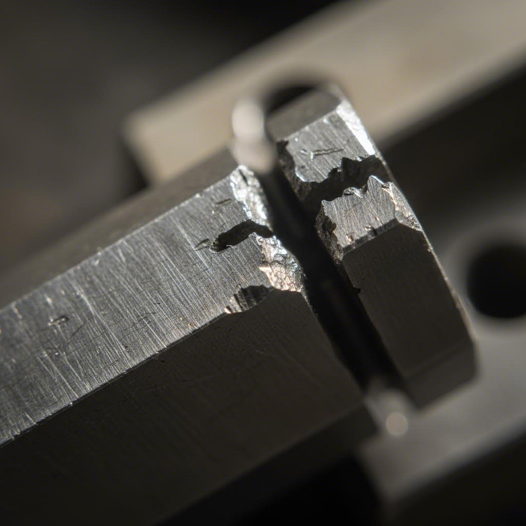
- Αποθρυψαλίσματα και μικρορωγμές – Εμφανίζεται ως μικρά κομμάτια που αποκόπτονται από τις ακμές κοπής. Συνήθως οφείλεται σε υπερβολική διαδρομή (clearance), φορτίο κρούσης ή σε χάλυβα μήτρας που είναι υπερβολικά σκληρός για τη συγκεκριμένη εφαρμογή. Αυτά τα θραύσματα μολύνουν τα εξαρτήματά σας και επιταχύνουν περαιτέρω ζημιές.
- Ρωγμές λόγω κόπωσης – Αναπτύσσεται ως προοδευτικές ρωγμές υπό επαναλαμβανόμενους κύκλους τάσης. Αναζητήστε τα χαρακτηριστικά «σημάδια παραλίας» — καμπύλες γραμμές που ακτινοβολούν από το σημείο προέλευσης της ρωγμής. Σε αντίθεση με τις ρωγμές λόγω αιφνίδιας υπερφόρτισης, οι ρωγμές κόπωσης αναπτύσσονται σταδιακά, προσφέροντας χρόνο προειδοποίησης, εφόσον πραγματοποιείτε τακτικές επιθεωρήσεις.
Τι πρέπει να προκαλεί άμεση διερεύνηση; Σύμφωνα με τη Jeelix, η αύξηση του ύψους του ακμαίου (burr) στα εξαρτήματα που έχουν υποστεί διαμόρφωση με μήτρα, η απόκλιση των διαστάσεων εκτός των ορίων ανοχής, οι γρατζουνιές στην επιφάνεια ή τα σημάδια γκαλινγκ (galling), καθώς και οι ασυνήθιστοι θόρυβοι κατά τη διαδικασία επεξεργασίας με μήτρα, όλα αυτά υποδηλώνουν την εξέλιξη προβλημάτων. Αυτά τα συμπτώματα σπάνια εμφανίζονται αιφνίδια — εντείνονται σταδιακά, από ελαφρά έως σοβαρά, εντός εκατοντάδων ή χιλιάδων κύκλων λειτουργίας του πρεσσό.
Προληπτική Συντήρηση που Επεκτείνει τη Διάρκεια Ζωής του Καλουπιού
Οι εγκαταστάσεις παραγωγής με την υψηλότερη απόδοση δεν περιμένουν τις βλάβες. Προγραμματίζουν τη συντήρηση βάσει των κύκλων παραγωγής, των δεδομένων επιθεώρησης και των ιστορικών προτύπων απόδοσης.
Σύμφωνα με The Phoenix Group μια κακή συντήρηση των καλουπιών προκαλεί ελαττώματα ποιότητας κατά τη διάρκεια της παραγωγής, αυξάνοντας το κόστος ταξινόμησης, αυξάνοντας την πιθανότητα αποστολής ελαττωματικών εξαρτημάτων και επιφέροντας τον κίνδυνο ακριβών αναγκαστικών μέτρων περιορισμού.
Καθορίστε τα διαστήματα επιθεώρησης βάσει των τυποποιημένων προδιαγραφών των καλουπιών σας και των απαιτήσεων της παραγωγής:
- Κάθε παραγωγική διαδικασία – Οπτική επιθεώρηση των κρίσιμων επιφανειών, επαλήθευση της ποιότητας των εξαρτημάτων, έλεγχος του συστήματος λίπανσης
- Εβδομαδιαίως ή διεβδομαδιαίως – Λεπτομερής εξέταση των ακμών του εμβόλου και του καλουπιού, μέτρηση των κρίσιμων διαστάσεων, αξιολόγηση της φθοράς των οδηγών πειρών και των βαλάκων
- Μηνιαία ή τριμηνιαία – Πλήρης αποσυναρμολόγηση του καλουπιού, ενδελεχής καθαρισμός, επαλήθευση των διαστάσεων σε σχέση με τις αρχικές προδιαγραφές, αντικατάσταση συστατικών όπως απαιτείται
- Κάθε χρόνο – Εκτενής επιθεώρηση, συμπεριλαμβανομένης μεταλλουργικής αξιολόγησης, εφόσον κρίνεται αναγκαίο, αξιολόγησης της κατάστασης των επιστρώσεων και ελέγχου των εγγράφων
Συνηθισμένα προβλήματα και οι λύσεις τους:
- Υπερβολικός σχηματισμός ακμών → Ελέγξτε και ρυθμίστε το κενό των μήτρων· ακονίστε ή αντικαταστήστε φθαρμένες κοπτικές ακμές
- Κόλληση στις επιφάνειες διαμόρφωσης → Βελτιώστε την λίπανση· εφαρμόστε ή επαναφέρετε επιφανειακές επιστρώσεις (TiN, DLC)· λειάνετε τις πληγείσες περιοχές
- Διαστασιακή απόκλιση → Επαληθεύστε τα κενά· ελέγξτε τα φθαρμένα καθοδηγητικά εξαρτήματα· επαναλειάνετε τις εργαζόμενες επιφάνειες σύμφωνα με τις προδιαγραφές
- Αποκόμματα στις κοπτικές ακμές → Αξιολογήστε την επιλογή του υλικού· μειώστε τα φορτία κρούσης· εξετάστε τη χρήση πιο ανθεκτικής ποιότητας χάλυβα για μήτρες
- Ρωγμές κόπωσης → Αποστρεσάρετε τα πληγέντα εξαρτήματα· ανασχεδιάστε τις περιοχές υψηλής τάσης· αντικαταστήστε τα πριν από την καταστροφική αστοχία
- Ζημιά στην πλάκα αποκόλλησης → Ελέγξτε τις δυνάμεις των ελατηρίων· επαληθεύστε το χρονισμό· αντικαταστήστε φθαρμένα εξαρτήματα
Πότε είναι λογική η αναγόνιση σε σύγκριση με την αντικατάσταση του εξαρτήματος; Γενικά, εάν ένας διαμπερής κοπτικός πύργος (punch) ή ένα κουμπί κοπής (die button) μπορεί να αναγονιστεί διατηρώντας τα ελάχιστα καθορισμένα όρια εργασίας, η αναγόνιση προσφέρει σημαντική οικονομία κόστους. Τα περισσότερα τυποποιημένα εξαρτήματα κοπής επιτρέπουν πολλαπλούς κύκλους αναγόνισης πριν από την ανάγκη αντικατάστασης. Ωστόσο, εξαρτήματα που εμφανίζουν ρωγμές κόπωσης, σοβαρή σύγκρουση (galling) ή διαστασιακή παραμόρφωση πέραν της δυνατότητας διόρθωσης πρέπει να αντικατασταθούν αμέσως.
Ο πλήρης κύκλος ζωής του καλουπιού
Η κατανόηση της φάσης στην οποία βρίσκεται το καλούπι σας στον κύκλο ζωής του σας βοηθά να σχεδιάσετε κατάλληλα τις επενδύσεις σε συντήρηση:
- Περίοδος Εξοικείωσης – Οι πρώτες 5.000–10.000 κρούσεις αποκαλύπτουν οποιαδήποτε προβλήματα σχεδιασμού ή κατασκευής. Πραγματοποιήστε συχνούς ελέγχους και καταγράψτε την αρχική απόδοση.
- Πρωταρχική παραγωγή – Το καλούπι λειτουργεί με αιχμή απόδοση με την τακτική συντήρηση. Αυτή η φάση θα πρέπει να αντιστοιχεί στο 70–80 % της συνολικής διάρκειας ζωής του καλουπιού.
- Ωριμότητα λειτουργίας – Απαιτείται αυξημένη συχνότητα συντήρησης. Η αντικατάσταση εξαρτημάτων καθίσταται πιο συχνή. Το κόστος ανά εξάρτημα αυξάνεται σταδιακά.
- Τέλος ζωής – Το κόστος συντήρησης προσεγγίζει ή υπερβαίνει το κόστος ανακατασκευής. Η ποιότητα γίνεται ασυνεπής παρά τις ενέργειες διόρθωσης. Έφτασε η ώρα για αντικατάσταση ή μεγάλη ανακατασκευή.
Η τεκμηρίωση καθ’ όλη τη διάρκεια αυτού του κύκλου ζωής αποδεικνύεται ανεκτίμητη. Σύμφωνα με εμπειρογνώμονες του κλάδου, τα δεδομένα από προηγούμενες εντολές εργασίας μπορούν να χρησιμοποιηθούν για τη βελτίωση των σχεδίων προληπτικής συντήρησης και για την πρόβλεψη των χρονικών στιγμών που μπορεί να επαναληφθούν παρόμοια προβλήματα. Αυτό το ιστορικό αρχείο μετατρέπει την αντιδραστική συντήρηση σε προγνωστική διαχείριση περιουσιακών στοιχείων.
Η παραγωγική διάρκεια ζωής του μήτρας σας εξαρτάται από την πρώιμη ανίχνευση προβλημάτων και τη συστηματική αντιμετώπισή τους. Ωστόσο, ακόμη και το καλύτερο πρόγραμμα συντήρησης δεν μπορεί να αντισταθμίσει μια κακή αρχική ποιότητα των μητρών — κάτι που μας οδηγεί στο κρίσιμο ερώτημα πώς να επιλέξουμε έναν εταίρο κατασκευής μητρών ικανό να παραδώσει μήτρες που λειτουργούν από την πρώτη μέρα.
Επιλογή ενός εξειδικευμένου εταίρου κατασκευής μητρών
Έχετε σχεδιάσει την τέλεια μηχανική μήτρα, έχετε καθορίσει υψηλής ποιότητας υλικά και έχετε θεσπίσει αυστηρά πρωτόκολλα συντήρησης. Αλλά εδώ είναι η δυσάρεστη αλήθεια: όλος αυτός ο προσεκτικός σχεδιασμός δεν σημαίνει τίποτα, εάν ο εταίρος σας για την κατασκευή μητρών δεν διαθέτει τις απαραίτητες δυνατότητες για την εκτέλεσή του. Η διαφορά μεταξύ ενός εξειδικευμένου κατασκευαστή μητρών και ενός ανεπαρκούς κατασκευαστή μπορεί να μεταφραστεί σε μήνες καθυστερήσεων, προβλημάτων ποιότητας που διαφεύγουν τον έλεγχο και κόστη που εκτοξεύονται πολύ πέρα από το αρχικό σας προϋπολογισμό για την κατασκευή των μητρών.
Πώς λοιπόν διαχωρίζετε τις εταιρείες κατασκευής μητρών παγκόσμιας τάξης από εκείνες που απλώς μιλούν καλά; Η απάντηση βρίσκεται σε μια συστηματική αξιολόγηση σε πέντε κρίσιμες διαστάσεις.
Πρότυπα πιστοποίησης που υποδηλώνουν αριστεία στην κατασκευή
Κατά την αξιολόγηση εταίρων για την κατασκευή εργαλείων και μητρών, οι πιστοποιήσεις αποτελούν το πρώτο σας φίλτρο. Δεν εγγυώνται αριστεία, αλλά η απουσία τους πρέπει να προκαλεί αμέσως σημάδια προειδοποίησης.
Πιστοποίηση iatf 16949 αποτελεί το χρυσό πρότυπο για τους προμηθευτές μητρών αυτοκινήτων. Σύμφωνα με Smithers αυτό το παγκοσμίως αναγνωρισμένο πρότυπο διαχείρισης ποιότητας καθορίζει τις απαιτήσεις για ένα Σύστημα Διαχείρισης Ποιότητας (ΣΔΠ) που βοηθά τις οργανώσεις να βελτιώσουν την αποδοτικότητα της παραγωγής και να ενισχύσουν την ικανοποίηση των πελατών. Η επίτευξη της πιστοποίησης IATF 16949 απαιτεί σημαντικές επενδύσεις σε χρόνο, χρήμα και πόρους — γεγονός που σημαίνει ότι οι πιστοποιημένοι προμηθευτές έχουν αποδείξει σοβαρή δέσμευση προς τα συστήματα ποιότητας.
Τι απαιτεί πραγματικά το πρότυπο IATF 16949; Οι κύριες απαιτήσεις περιλαμβάνουν:
- Ισχυρό Σύστημα Διαχείρισης Ποιότητας – Βασίζεται στα θεμέλια του ISO 9001:2015 με ενισχύσεις ειδικές για τον αυτοκινητοβιομηχανικό τομέα
- Σχεδιασμός και Ανάλυση Κινδύνων – Αναγνώριση και μείωση δυνητικών κινδύνων σε όλα τα στάδια της παραγωγής
- Διαχείριση Διαδικασιών – Τεκμηριωμένες διαδικασίες με τακτική παρακολούθηση της αποτελεσματικότητάς τους
- Σχεδίαση και ανάπτυξη προϊόντων – Καλά τεκμηριωμένες διαδικασίες σχεδιασμού που ανταποκρίνονται στις απαιτήσεις των πελατών και στους κανονισμούς ασφαλείας
- Συνεχής Παρακολούθηση και Μέτρηση – Τακτικοί ελέγχους, επιθεωρήσεις και αξιολογήσεις απόδοσης
Πέρα από το IATF 16949, αναζητήστε ως ελάχιστο κριτήριο πιστοποίηση σύμφωνα με το ISO 9001, πιστοποίηση ISO 14001 για τη δέσμευση στη διαχείριση του περιβάλλοντος και τυχόν ειδικές πιστοποιήσεις για τον συγκεκριμένο κλάδο που αφορά την εφαρμογή σας (αεροδιαστημικός, ιατρικός κ.λπ.).
Αξιολόγηση της μηχανικής υποστήριξης και των δυνατοτήτων πρωτοτύπων
Οι πιστοποιήσεις επιβεβαιώνουν την ύπαρξη συστημάτων. Οι μηχανικές δυνατότητες καθορίζουν εάν αυτά τα συστήματα παράγουν εξαιρετικά μήτρες ή απλώς ικανοποιητικά.
Σύμφωνα με εμπειρογνώμονες στην κατασκευή μητρών εκτύπωσης της Die-Matic, ένας κατασκευαστής που προσφέρει βελτιστοποίηση του σχεδιασμού των εξαρτημάτων μπορεί να βοηθήσει στη διαμόρφωση των σχεδίων σας για καλύτερη εφικτότητα παραγωγής, να επιλύσει γρήγορα προβλήματα και να διατηρήσει τα έργα στο χρονοδιάγραμμα. Αυτή η συνεργατική προσέγγιση μηχανικής διαχωρίζει τους πραγματικούς εταίρους από τους απλούς λήπτες παραγγελιών, οι οποίοι κατασκευάζουν απλώς ό,τι ορίζετε εσείς — ακόμη και όταν οι προδιαγραφές σας περιλαμβάνουν προβλήματα που θα μπορούσαν να αποφευχθούν.
Κατά την αξιολόγηση ενός πιθανού κατασκευαστή συναρμολόγησης μητρών, εξετάστε τις ακόλουθες μηχανικές διαστάσεις:
- Δυνατότητες προσομοίωσης CAE – Χρησιμοποιεί ο προμηθευτής λογισμικό προσομοίωσης διαμόρφωσης για να προβλέψει τη ροή του υλικού, την ελαστική ανάκαμψη (springback) και τυχόν ενδεχόμενα ελαττώματα πριν από την κατασκευή των καλουπιών; Προηγμένες προσομοιώσεις CAE επιτρέπουν εικονικές δοκιμές καλουπιών, οι οποίες εντοπίζουν προβλήματα σε στάδιο όπου η διόρθωσή τους απαιτεί ώρες μηχανικού σχεδιασμού αντί για τροποποιήσεις των καλουπιών.
- Υποστήριξη Σχεδίασης για Δυνατότητα Κατασκευής – Θα προτείνουν οι μηχανικοί τους ενεργά αλλαγές που μειώνουν την πολυπλοκότητα των καλουπιών, βελτιώνουν τη διάρκεια ζωής των ματρίτσων ή αυξάνουν την ποιότητα των εξαρτημάτων;
- Ταχύτητα Πρωτοτύπησης – Με ποια ταχύτητα μπορούν να παραδώσουν πρωτότυπα καλούπια για επικύρωση; Η ταχεία πρωτοτυποποίηση — σε χρονικό διάστημα ως και 5 ημερών για ορισμένους προμηθευτές — συρρικνώνει δραστικά το χρονοδιάγραμμα ανάπτυξής σας.
- Ειδικότητα Υλικών – Διαθέτουν επαληθευμένη εμπειρία με τα συγκεκριμένα υλικά εργασίας σας; Διαφορετικά υλικά απαιτούν διαφορετικές μεθόδους χειρισμού, προσεγγίσεις καλουποποίησης και παραμέτρους διαδικασίας.
Όπως τονίζουν οι εμπειρογνώμονες της Eigen Engineering στον κλάδο, όταν ένας κατασκευαστής διαφημίζει μόνο ένα είδος υπηρεσίας, οι δυνατότητές του είναι περιορισμένες. Ο ιδανικός εταίρος κατασκευής μήτρας προσφέρει ολοκληρωμένες υπηρεσίες, συμπεριλαμβανομένης της υποστήριξης στον σχεδιασμό μητρών, της ικανότητας εργασίας με πολλαπλά υλικά και της ενσωμάτωσης αυτοματοποίησης.
Δυναμικό Παραγωγής και Μετρικά Ποιότητας
Η μηχανική αριστεία δεν σημαίνει τίποτα, αν ο προμηθευτής σας δεν μπορεί να παραδώσει τις μήτρες εγκαίρως — ή αν οι παραδοθείσες μήτρες απαιτούν εκτεταμένη επανεργασία προτού παράγουν αποδεκτά εξαρτήματα.
Σύμφωνα με τους εμπειρογνώμονες κατασκευής της Die-Matic, πρέπει να διασφαλίσετε ότι επιλέγετε έναν κατασκευαστή ικανό να καλύψει τις απαιτήσεις όγκου παραγωγής σας. Τα έργα υψηλού όγκου απαιτούν αυτοματοποιημένες διαδικασίες και υψηλή χωρητικότητα παραγωγής, ενώ οι πρωτότυπες παρτίδες απαιτούν ευελιξία και εμπειρογνωμοσύνη σε μικρότερα μεγέθη παρτίδων. Επαληθεύστε ότι ο πιθανός εταίρος σας μπορεί να αναπτύσσεται σταδιακά μαζί με τις ανάγκες παραγωγής σας.
Τα μετρικά ποιότητας αποκαλύπτουν όσα δεν μπορούν να δείξουν τα πιστοποιητικά. Ρωτήστε τους πιθανούς προμηθευτές σχετικά με:
- Ποσοστό έγκρισης πρώτης εξέτασης – Ποιο ποσοστό των καλουπιών πληροί τις προδιαγραφές χωρίς τροποποίηση; Οι κορυφαίοι προμηθευτές επιτυγχάνουν ποσοστά άνω του 90 %, ενώ οι εξαιρετικοί συνεργάτες υπερβαίνουν το 93 %.
- Απόδοση έγκαιρης παράδοσης – Το ιστορικό είναι πιο σημαντικό από τις υποσχέσεις. Ζητήστε στοιχεία από τους τελευταίους 12 μήνες.
- Την κράτηση πελατών – Πόσο καιρό συνεργάζονται οι κύριοι πελάτες τους με αυτούς; Οι μακροχρόνιες σχέσεις υποδηλώνουν συνεχή ικανοποίηση.
- Χρόνος αντίδρασης σε διορθωτικές ενέργειες – Όταν προκύψουν προβλήματα (και θα προκύψουν), πόσο γρήγορα ανταποκρίνεται και επιλύει τα ζητήματα ο προμηθευτής;
Ο Έλεγχος Αξιολόγησης του Προμηθευτή σας
Πριν οριστικοποιήσετε οποιαδήποτε συνεργασία κατασκευής καλουπιών εκτύπωσης, ελέγξτε συστηματικά τα παρακάτω κριτήρια:
- ☐ Επιβεβαιωμένα πιστοποιητικά – Επιβεβαιωμένα και ενήμερα πιστοποιητικά IATF 16949, ISO 9001 και βιομηχανικά ειδικά πρότυπα
- ☐ Επιδεικνυόμενες μηχανικές δυνατότητες – Διαθεσιμότητα υπηρεσιών προσομοίωσης CAE, υποστήριξης DFM και βελτιστοποίησης σχεδιασμού
- ☐ Επιβεβαιώθηκε ο χρονοδιάγραμμα πρωτοτύπων – Οι δυνατότητες γρήγορης πρωτοτυποποίησης ευθυγραμμίστηκαν με το πρόγραμμα ανάπτυξής σας
- ☐ Η παραγωγική ικανότητα είναι επαρκής – Επιβεβαιώθηκε η ικανότητα κλιμάκωσης από το πρωτότυπο μέχρι την παραγωγή μεγάλης κλίμακας
- ☐ Αξιολογήθηκαν τα μετρήσιμα κριτήρια ποιότητας – Εξετάστηκαν οι ποσοστώσεις πρώτης έγκρισης, η απόδοση παράδοσης και τα δεδομένα επαναλαμβανόμενης επιχειρηματικής σχέσης με τους πελάτες
- ☐ Αξιολογήθηκε η χρηματοοικονομική σταθερότητα – Αξιολογήθηκαν τα χρόνια λειτουργίας, η διάρκεια θητείας της διοίκησης και η ποικιλομορφία της βάσης πελατών
- ☐ Καθορίστηκαν οι πρωτόκολλα επικοινωνίας – Καθορίστηκαν σαφείς σημεία επαφής, η συχνότητα υποβολής εκθέσεων και οι διαδικασίες επείγουσας αντιμετώπισης προβλημάτων
- ☐ Επισκέψη εγκαταστάσεων ολοκληρώθηκε Εκτίμηση επί τόπου του εξοπλισμού, των διαδικασιών και των δυνατοτήτων της ομάδας
- ☐ Επαφές με τα στοιχεία αναφοράς άμεσες συνομιλίες με τους σημερινούς πελάτες σε παρόμοιες εφαρμογές
- ☐ Συνολικά αναλυθέντα κόστη Ταχυδρομικές μεταφορές, τιμολόγια, έξοδα συμμόρφωσης και κρυμμένα τέλη που εντοπίζονται και συγκρίνονται
Για εφαρμογές αυτοκινήτων ειδικά, Λύσεις ακριβείας καλουπιών διαμόρφωσης Shaoyi να δείξουν τι φέρνουν οι ειδικευμένοι προμηθευτές στο τραπέζι: πιστοποίηση IATF 16949 που υποστηρίζει τα συστήματα ποιότητας τους, προηγμένη προσομοίωση CAE για αποτελέσματα χωρίς ελαττώματα, ταχεία κατασκευή πρωτοτύπων σε μόλις 5 ημέρες και ποσοστό έγκρισης πρώτης έγκρισης 93% Η εστίαση της ομάδας μηχανικών τους σε οικονομικά αποδοτικά, υψηλής ποιότητας εργαλεία προσαρμοσμένα στα πρότυπα OEM αποδεικνύει τις ολοκληρωμένες δυνατότητες που θα πρέπει να αναζητήσετε σε οποιονδήποτε συνεργάτη κατασκευής πετσέτας.
Όπως αναφέρει η Eigen Engineering, ο τέλειος κατασκευαστής μήτρας εμβολοπλαστικής διατηρεί ειλικρινείς διαδικασίες, δημιουργεί επαρκείς σημεία επαφής και συμμορφώνεται πλήρως με όλες τις γραπτές απαιτήσεις σας για την παραγωγή, ενώ είναι προληπτικός όσον αφορά τις διαταραχές ή τις αλλαγές στην αλυσίδα εφοδιασμού. Η εύρεση αυτού του επιπέδου εταιρικής σχέσης απαιτεί εξονυχιστική αξιολόγηση εξαρχής — ωστόσο, η επένδυση αποδίδει αποδόσεις σε όλη τη διάρκεια του προγράμματος παραγωγής σας.
Με τον προμηθευτή σας επιλεγμένο και την αξιολόγηση ολοκληρωμένη, είστε έτοιμοι να συνθέσετε όλα όσα έχετε μάθει σε εφαρμόσιμες προδιαγραφές για το επόμενο μηχανικό σας έργο μήτρας.
Λήψη Ενημρωμένων Αποφάσεων για τα Έργα Κατασκευής Μητρών σας
Έχετε διανύσει ολόκληρη την ανατομία των μηχανικών μητρών — από τους βασικούς ορισμούς μέχρι τα κριτήρια επιλογής προμηθευτών. Τώρα έρχεται η στιγμή που διαχωρίζει τους ενημερωμένους αγοραστές από εκείνους που μαθαίνουν ακριβά μαθήματα στην παραγωγική γραμμή. Πώς μετατρέπετε αυτές τις γνώσεις σε προδιαγραφές που εξασφαλίζουν αποτελέσματα;
Η ορολογία «εργαλεία και μήτρες» περιλαμβάνει πολύ περισσότερα από τα εργαλεία κοπής μετάλλων. Η κατανόηση της πρακτικής σημασίας των εργαλείων και των μητρών σημαίνει ότι κάθε απόφαση που λαμβάνετε — από τον τύπο της μήτρας έως την ποιότητα του υλικού και τον εταίρο κατασκευής — επηρεάζει ολόκληρο το πρόγραμμα παραγωγής σας. Ας εξετάσουμε τους κρίσιμους παράγοντες που καθορίζουν την επιτυχία.
Βασικά συμπεράσματα για την επιτυχή προδιαγραφή μητρών
Τα πιο δαπανηρά λάθη στην αγορά μητρών δεν οφείλονται σε κακές επιλογές υλικού ή ανεπαρκή συντήρηση, αλλά σε αντιφατικές προδιαγραφές που δεν αντιστοιχούν στις πραγματικές απαιτήσεις παραγωγής σας.
Η επιλογή της μήτρας σας πρέπει να βασίζεται σε τέσσερεις θεμελιώδεις ερωτήσεις:
- Όγκος παραγωγής – Οι προοδευτικές μήτρες είναι ιδανικές για παρτίδες που υπερβαίνουν τα 100.000 τεμάχια· οι σύνθετες μήτρες εξυπηρετούν οικονομικά μικρότερες ποσότητες· οι μήτρες μεταφοράς (transfer dies) αντιμετωπίζουν πολύπλοκες γεωμετρίες ανεξάρτητα από την ποσότητα
- Περιπλοκότητα Κομματιού – Οι απλές επίπεδες εργασίες προτιμούν τις σύνθετες μήτρες· οι πολυσταθμικές προοδευτικές μήτρες αντιμετωπίζουν με αποτελεσματικότητα μεσαίου βαθμού πολυπλοκότητας· τα συστήματα μεταφοράς (transfer systems) επιτρέπουν βαθιές διαμορφώσεις (deep draws) και αλλαγές προσανατολισμού
- Υλικές αιτίες – Το υλικό του εξαρτήματός σας καθορίζει τους βαθμούς χάλυβα για μήτρες, τις επιτρεπόμενες ανοχές και τις επιφανειακές επεξεργασίες. Οι υψηλής αντοχής χάλυβες και το αλουμίνιο απαιτούν εκάστοτε ειδικές προσεγγίσεις στην κατασκευή εργαλείων
- Συνολικό Κόστος Ιδιοκτησίας – Η αρχική τιμή της μήτρας αντιπροσωπεύει μόνο το 20–30 % του συνολικού κόστους κατά τη διάρκεια ζωής της. Το κόστος συντήρησης, οι κύκλοι ξύσιμας, η αντικατάσταση εξαρτημάτων και ο χρόνος αδράνειας συσσωρεύονται σημαντικά κατά τη διάρκεια εκατομμυρίων κύκλων πίεσης
Σύμφωνα με έρευνα του κλάδου για τις τάσεις στον τομέα των μητρών και των εργαλείων , οι αγοραστές δίνουν όλο και περισσότερη προτεραιότητα στο συνολικό κόστος κατοχής έναντι της αρχικής τιμής—αναγνωρίζοντας ότι η συντήρηση, η διάρκεια ζωής και η συνέπεια της ποιότητας έχουν μεγαλύτερη βαρύτητα από τις αρχικές οικονομίες, οι οποίες μπορεί να προκαλέσουν προβλήματα σε μεταγενέστερα στάδια
Τα επόμενα βήματά σας στην κατασκευή μητρών
Ετοιμοι να περάσετε από τη γνώση στην πράξη; Η πορεία σας προς τα εμπρός εξαρτάται από τον ρόλο σας και τις άμεσες προτεραιότητές σας.
Για Μηχανικούς:
- Πραγματοποιήστε επιθεώρηση των τρέχουσων σχεδίων των εξαρτημάτων σας όσον αφορά την εφικτότητα κατασκευής τους—συμβουλευτείτε εμπειρογνώμονες στην κατασκευή μητρών προτού οριστικοποιήσετε τις προδιαγραφές
- Ζητήστε δεδομένα προσομοίωσης CAE από πιθανούς προμηθευτές για να επιβεβαιώσετε τις προβλέψεις διαμόρφωσης
- Καταγράψτε τις κρίσιμες ανοχές και τις λειτουργικές τους απαιτήσεις για να καθοδηγήσετε τις αποφάσεις σχετικά με την ελεύθερη διάσταση των καλουπιών
- Καθορίστε τις απαιτήσεις για την αντιστάθμιση της ελαστικής επαναφοράς βάσει των συγκεκριμένων βαθμών υλικού που χρησιμοποιείτε
Για ειδικούς προμηθειών:
- Επαληθεύστε την πιστοποίηση IATF 16949 ή ισοδύναμη προτού προσθέσετε προμηθευτές στον κατάλογο εγκεκριμένων προμηθευτών σας
- Ζητήστε δεδομένα σχετικά με το ποσοστό πρώτης επιτυχούς εγκρίσεως και μετρικές εντός προθεσμίας παράδοσης για τους τελευταίους 12 μήνες
- Αξιολογήστε το συνολικό κόστος, συμπεριλαμβανομένων των μεταφορών, των τελωνειακών δασμών και του δυνητικού επανασχεδιασμού — όχι μόνο τις προσφερόμενες τιμές για τα εργαλεία πίεσης καλουπιών
- Επαληθεύστε ότι οι χρονοδιαγράμματα πρωτοτύπων συμβαδίζουν με τις απαιτήσεις του χρονοδιαγράμματος ανάπτυξής σας
Για Διευθυντές Παραγωγής:
- Καθορίστε διαστήματα προληπτικής συντήρησης βάσει του αριθμού των κινήσεων (strokes), και όχι βάσει χρονικής περιόδου
- Εκπαιδεύστε τους χειριστές να αναγνωρίζουν πρώιμα σημάδια προειδοποίησης — αλλαγές στο ύψος των ακμών, διαστατική παρέκκλιση, ασυνήθιστους θορύβους
- Καταγράψτε δεδομένα σχετικά με την απόδοση των εργαλείων πίεσης για να διαμορφώσετε μελλοντικές προδιαγραφές και αξιολογήσεις προμηθευτών
- Δημιουργήστε σχέσεις με προμηθευτές που προσφέρουν συνεχή μηχανική υποστήριξη, όχι απλώς παράδοση των εργαλείων στην αρχή
Η διαφορά μεταξύ ενός καλουπιού που λειτουργεί επί χρόνια και ενός άλλου που απαιτεί συνεχή παρέμβαση συχνά οφείλεται σε αποφάσεις που λήφθηκαν πριν ακόμη κοπεί το πρώτο κομμάτι χάλυβα.
Είτε καθορίζετε για πρώτη φορά το καλούπι σας είτε βελτιστοποιείτε μια ήδη καθιερωμένη διαδικασία κοπής με τσιμπίδι, οι αρχές παραμένουν οι ίδιες: προσαρμόστε τα εργαλεία σας στις πραγματικές απαιτήσεις παραγωγής σας, επενδύστε κατάλληλα σε υλικά και μηχανική, επιλέξτε εταίρους με αποδεδειγμένες ικανότητες και διατηρείτε προληπτικά τα περιουσιακά στοιχεία σας.
Για αυτοκινητοβιομηχανικές εφαρμογές, όπου η ακρίβεια και η αξιοπιστία είναι αναπόφευκτες, η εξέταση επαγγελματικών λύσεων καλουπιών κοπής από εξειδικευμένους κατασκευαστές αποτελεί ένα σημείο εκκίνησης για τη μετατροπή αυτών των αρχών σε εργοστασιακά έτοιμα εργαλεία. Η επένδυση που πραγματοποιείτε σε μια εξονυχιστική προδιαγραφή και στην επιλογή κατάλληλων εταίρων αποφέρει αποδόσεις σε κάθε εξάρτημα που παράγεται με τα καλούπια σας.
Συχνές Ερωτήσεις Σχετικά με Μηχανικά Καλούπια
1. Τι είναι ένα μηχανικό καλούπι;
Ένα μηχανικό καλούπι είναι ένα ειδικευμένο εργαλείο μηχανής που χρησιμοποιείται στην παραγωγή για το κόψιμο, τη διαμόρφωση ή την ενσωμάτωση υλικών — συνήθως μετάλλων — σε επιθυμητά σχήματα μέσω εφαρμοζόμενης πίεσης. Σε αντίθεση με τα καλούπια έγχυσης, τα οποία λειτουργούν με τήγματα υλικά, τα μηχανικά καλούπια μετατρέπουν φυσικά στερεό ελάσματα από μέταλλο χρησιμοποιώντας δύο ακριβώς ταιριαστά ημικάλουπα που τοποθετούνται εντός μιας πρεσαριστικής μηχανής. Εκτελούν τέσσερις βασικές λειτουργίες: προσδιορισμό της θέσης, σύσφιξη, επεξεργασία (κοπή, κάμψη, διαμόρφωση) και απελευθέρωση του τελικού εξαρτήματος. Εξειδικευμένοι κατασκευαστές, όπως η Shaoyi, χρησιμοποιούν προηγμένη προσομοίωση CAE για να διασφαλίσουν την ανεπιφύλακτη λειτουργία του καλουπιού.
2. Γιατί ένα ολοκληρωμένο κύκλωμα ονομάζεται «die»;
Στην κατασκευή ημιαγωγών, ο όρος «die» (δίσκος) αναφέρεται στα μεμονωμένα κομμάτια ολοκληρωμένων κυκλωμάτων που αποκόπτονται από ένα μεγαλύτερο πλακίδιο πυριτίου κατά τη διαδικασία κατασκευής. Το πλακίδιο τέμνεται — ή «διαχωρίζεται» (dicing) — σε ξεχωριστά κομμάτια, καθένα από τα οποία περιέχει ένα πλήρες κύκλωμα. Αυτό διαφέρει από τα μηχανικά dies (μήτρες) στην επεξεργασία μετάλλων, τα οποία είναι εργαλεία κοπής και διαμόρφωσης και όχι τα ίδια τα προϊόντα. Και οι δύο χρήσεις μοιράζονται την κοινή ιδέα της ακριβούς κοπής για τη δημιουργία λειτουργικών εξαρτημάτων.
3. Ποιοι είναι οι κύριοι τύποι μηχανικών μητρών (dies) που χρησιμοποιούνται στην παραγωγή;
Οι τρεις κύριοι μηχανικοί τύποι μήτρας είναι οι προοδευτικές μήτρες, οι σύνθετες μήτρες και οι μήτρες μεταφοράς. Οι προοδευτικές μήτρες εκτελούν πολλαπλές διαδοχικές λειτουργίες καθώς το υλικό προχωρά μέσω των σταθμών—είναι ιδανικές για παραγωγή μεγάλου όγκου, που υπερβαίνει τα 100.000 τεμάχια. Οι σύνθετες μήτρες εκτελούν πολλαπλές κοπτικές λειτουργίες ταυτόχρονα σε μία κίνηση, προσφέροντας εξαιρετική ακρίβεια για απλούστερες γεωμετρίες. Οι μήτρες μεταφοράς χρησιμοποιούν μηχανικά δάχτυλα ή ρομπότ για να μετακινούν τα τεμάχια εργασίας μεταξύ ανεξάρτητων σταθμών, χειριζόμενες περίπλοκα τρισδιάστατα εξαρτήματα και βαθιές διαμορφώσεις που άλλα συστήματα δεν μπορούν να επιτύχουν.
4. Πώς επιλέγω το κατάλληλο χάλυβα εργαλείων για τη μήτρα σφράγισης μου;
Η επιλογή του χάλυβα εργαλείων εξαρτάται από τον όγκο παραγωγής, τη σκληρότητα του υλικού του τεμαχίου εργασίας και τις απαιτήσεις ακρίβειας. Ο χάλυβας εργαλείων D2 προσφέρει εξαιρετική αντοχή στη φθορά για επιχειρήσεις κοπής και διατρήσεων μεγάλης διάρκειας. Ο χάλυβας A2 προσφέρει ισορροπημένη αντοχή και διαστασιακή σταθερότητα για εφαρμογές γενικού σκοπού. Ο χάλυβας S7 ξεχωρίζει σε σενάρια υψηλής επιρροής που απαιτούν αντοχή σε κρούση. Για εφαρμογές ακραίας φθοράς, οι ενσωματώσεις καρβιδίου βολφραμίου μπορούν να επεκτείνουν τη διάρκεια ζωής των καλουπιών 5–10 φορές σε σύγκριση με το χάλυβα εργαλείων. Επιφανειακές επεξεργασίες, όπως επιστρώσεις TiN ή DLC, βελτιώνουν περαιτέρω την απόδοση και τη διάρκεια ζωής.
5. Ποια πιστοποιητικά πρέπει να αναζητήσω κατά την επιλογή ενός εταίρου κατασκευής καλουπιών;
Η πιστοποίηση IATF 16949 αποτελεί το «χρυσό πρότυπο» για τους προμηθευτές καλουπιών αυτοκινήτων, δείχνοντας τη δέσμευσή τους για αξιόπιστα συστήματα διαχείρισης ποιότητας. Αναζητήστε προμηθευτές με πιστοποίηση ISO 9001 ως ελάχιστο απαιτούμενο επίπεδο, καθώς και βιομηχανικά ειδικές πιστοποιήσεις που αντιστοιχούν στη συγκεκριμένη εφαρμογή σας. Πέραν των πιστοποιήσεων, αξιολογήστε τις μηχανικές δυνατότητες, συμπεριλαμβανομένης της προσομοίωσης CAE, της ταχύτητας πρωτότυπης κατασκευής (ορισμένοι προμηθευτές, όπως η Shaoyi, προσφέρουν παράδοση σε 5 ημέρες), του ποσοστού έγκρισης στην πρώτη προσπάθεια (στόχος πάνω από 90 %) και της επίδοσης στην εντός προθεσμίας παράδοσης. Οι επαληθευμένες πιστοποιήσεις, σε συνδυασμό με ισχυρά μετρήσιμα κριτήρια ποιότητας, υποδεικνύουν έναν αξιόπιστο εταίρο κατασκευής.