 Små partier, høje standarder. Vores hurtige prototyperingservice gør validering hurtigere og nemmere —

Metal Laser-skæring Design: Fra CAD-fil til fejlfri produktion
Hvorfor metal laserudskæringsdesign bestemmer fremstillings succes
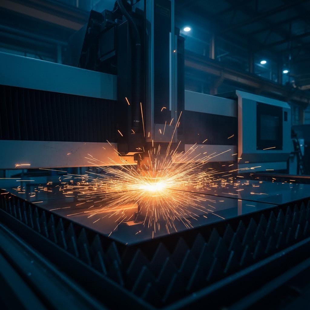
Forestil dig at bruge timer på at perfektionere en CAD-model, kun for at opdage, at din smukke del krøller, brænder eller simpelthen ikke kan produceres som tiltænkt. Frustrerende, ikke sandt? Dette scenarie opstår oftere end man måske tror, og det kan næsten altid spores tilbage til én afgørende faktor: selve designet.
Metal laserudskæringsdesign fungerer som den afgørende bro mellem din kreative vision og produktionens virkelighed. Hvert valg, du foretager i CAD-trinnet, påvirker direkte produktionssucces, omkostningseffektivitet og den endelige delkvalitet. Uanset om du er en hobbyist, der fremstiller brugerdefinerede beslag i dit værksted, eller en professionel ingeniør, der udvikler præcisionskomponenter til fly- og rumfartsapplikationer, vil forståelsen af denne sammenhæng ændre måden, du tilgår hvert projekt på.
Hvor design møder præcisionsproduktion
Her er, hvad mange artikler om laserskæring af metal gør forkert: De fokuserer næsten udelukkende på maskinspecifikationer og teknologi. Men sandheden er, at den mest avancerede laserskæreudstyr i verden ikke kan kompensere for dårlige designvalg. En konstruktør, der forstår produktionsbegrænsninger, vil konsekvent yde bedre end en, der behandler CAD-arbejde som noget rent estetisk.
Overvej skæregabet, som er det smalle spalte, der opstår, når laseren fordamper materiale under skæringen. Ifølge Komaspecs DFM-vejledninger bestemmer denne tilsyneladende mindre detalje, om dine samlede dele passer perfekt sammen eller kræver dyre omfremstillinger. De tolerancer, du angiver, de hullængder, du vælger, og selv hjørneradiuserne i dit design påvirker, om din del forlader skærebordet klar til brug eller ender i søvnen.
Konstruktørens rolle i succes med laserskæring
Din rolle rækker langt ud over blot at skabe geometri, der ser korrekt ud på skærmen. Effektiv design til laserudskæring kræver, at du tænker som en producent, mens du designer. Det betyder, at du skal forstå, at dele med en tykkelse over 25 mm ofte giver ru overflader og varmedeformationer, mens materialer under 0,5 mm kan flytte sig under laserudskæring, hvilket medfører nøjagtighedsproblemer.
Gennem denne guide vil du opdage, hvordan du optimerer dine designs til produktion ved at lære:
- Hvordan forskellige lasertyper påvirker dine konstruktionsmål og materialevalg
- Materialebestemte retningslinjer, der forhindrer almindelige fejl
- Kerf-kompensationsteknikker til præcise samling
- Arbejdsgange til filforberedelse, der eliminerer produktionsforsinkelser
- Omkostningsbesparende strategier integreret direkte i din designtilgang
Uanset om du forbereder filer til et lokalt produktionsshop eller indsender designs til en online skæretjeneste, er principperne de samme. Behersk disse grundlæggende regler, og du udvikler dig fra en, der blot laver CAD-filer, til en designer, der konsekvent leverer produkter, der kan produceres, er omkostningseffektive og af høj kvalitet.
Forståelse af lasertyper og deres indvirkning på designvalg
Har du nogensinde indsendt en designfil, kun for at få spørgsmålet fra producenten, hvilken lastype du har som mål? Hvis det spørgsmål tog dig på sengen, er du ikke alene. Mange designere behandler laserskæring som en enkelt ensartet proces, men virkeligheden er ganske anderledes. Den laserteknologi, der bruges til at skære dine dele, former fundamentalt, hvad der er muligt i dit design.
Tænk på det sådan her: valg af laser til skæring af stål er ligesom at vælge det rigtige værktøj fra en værktøjskasse. En fiberlaser, CO2-laser og Nd:YAG-laser har hver deres specifikke egenskaber. At forstå disse forskelle, inden du færdiggør din CAD-fil, forhindrer dyre omkonstruktioner og sikrer, at dine dele fremstilles præcist som tiltænkt.
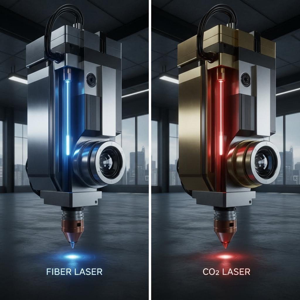
Fiber vs CO2 laser – designovervejelser
Den mest almindelige beslutning, du står over for, handler om at vælge mellem fiber- og CO2-lasere. Ifølge Xometrys tekniske sammenligning ligger den grundlæggende forskel i bølgelængden: fiberlasere udsender lys ved 1064 nm, mens CO2-lasere fungerer ved 10.600 nm. Den ti-dobbelte forskel i bølgelængde påvirker dramatisk, hvordan materialer absorberer laserenergien.
Hvorfor er bølgelængde vigtig for dit design? Kortere bølgelængder fokuserer til smallere punkter, hvilket gør det muligt for fiberydelasere at opnå finere detaljer og strammere tolerancer på metaldele. Fiberydelasere leverer cirka 3 til 5 gange højere produktivitet end tilsvarende CO2-maskiner, når de arbejder med passende materialer. De producerer også mere stabile og smalere stråler, der kan fokuseres mere præcist, hvilket resulterer i renere snit med mindre varmepåvirkede zoner.
Når du har brug for en laser til effektiv skæring af metalplader, tilbyder fiberteknologi typisk den bedste kombination af hastighed, præcision og kantkvalitet for de fleste metaller under 20 mm tykkelse. CO2-lasere forbliver dog det foretrukne valg til tykkere stålplader, især når der bearbejdes materialer over 10-20 mm, hvor operatører ofte tilføjer ilttilførsel for at fremskynde skæringen af plader op til 100 mm tykkelse.
Match dit design med laserteknologi
Dine designparametre bør være i overensstemmelse med den laserteknologi, som din producent bruger. Sådan ser det ud i praksis:
- Minimumsfeaturestørrelser: Fiberlasere kan opnå mindre huller og finere detaljer end CO2-lasere på tynde metaller, hvilket giver dig mulighed for at designe funktioner så små som materialetykkelsen
- Forventede tolerancer: Fiberlasere leverer typisk højere skærepræcision, så du kan angive strammere tolerancer, når du designer til fiberskæring
- Materialevalg: Reflekterende metaller som kobber, messing og aluminium skæres mere pålideligt med fiberlasere på grund af bedre absorption ved kortere bølgelængder
- Krav til kantafslutning: For applikationer, der kræver glatte, burrfrie kanter, giver fiberlasere generelt bedre resultater på tynde til mellemstore metaller
Nd:YAG-lasere fylder en specialiseret niche, idet de tilbyder høj topmængde til applikationer, der kræver dyb gravering, præcisions svejsning eller skæring gennem særlig tykke materialer. Ifølge ADHMT's specifikationsvejledning , disse faststoflasere har store anvendelser i bilindustrien, forsvars- og rumfartsindustrien, hvor både præcision og effekt er kritiske.
| Laser type | Bedste metalapplikationer | Typisk tykkelseomfang | Indvirkning af konstruktions tolerance | Karakteristik af kantkvalitet |
|---|---|---|---|---|
| Fiber laser | Rustfrit stål, aluminium, kobber, messing, titanium | 0,5 mm - 20 mm | ±0,05 mm opnåelig; fremragende til præcisionsdele | Glat, minimalt burr; overlegen på reflekterende metaller |
| CO2-laser | Kulstofstål, rustfrit stål (tykt), blødt stål | 6 mm - 25 mm+ (op til 100 mm med ilttilførsel) | typisk ±0,1 mm; tilstrækkelig til strukturelle komponenter | God kvalitet; kan vise svag oxidation ved kanterne |
| Nd:YAG laser | Højstærke legeringer, specialmetaller, tykke materialer | 1 mm – 50 mm | ±0,05 mm mulig; høj præcisionskapacitet | Udmærket til dybe snit; ren snitkvalitet ved korrekte parametre |
Når du forbereder dine designfiler, bør du overveje at spørge din fremstiller, hvilken type laser de vil bruge. Dette simple spørgsmål giver dig mulighed for at optimere din geometri, tolerancer og detaljestørrelser i overensstemmelse hermed. En 3 kW fiberlaser kan skære 10 mm rustfrit stål med høj kvalitet, men at opnå det samme resultat på 30 mm materiale kræver mindst 12 kW.
Forskellen i driftseffektivitet påvirker også dine projektomkostninger. Fiberlasere opnår en elektrisk effektivitet på over 90 % i forhold til kun 5–10 % for CO₂-systemer, og deres levetid er ofte over 25.000 timer – cirka 10 gange længere end for CO₂-enheder. Disse faktorer resulterer i lavere omkostninger pr. del for passende anvendelser, hvilket gør fiberlaserskæring stadig mere dominerende inden for metalbearbejdning.
Når valget af laserteknologi er afklaret, handler det næste afgørende skridt om at forstå, hvordan specifikke materialer opfører sig under betingelserne for laserskæring, og hvilke designjusteringer hvert enkelt materiale kræver.
Materialebestemte retningslinjer for almindelige metaller
Du har valgt den rigtige laserteknologi til dit projekt. Nu kommer et lige så vigtigt spørgsmål: hvordan tilpasser du dit design til det specifikke metal, du skal skære i? Hvert materiale medbringer unikke egenskaber, der direkte påvirker dine designvalg – fra minimums størrelse på detaljer til behandling af hjørner.
Forestil dig, at du designer et beslag i 3 mm aluminium med de samme parametre, som du ville bruge til 3 mm stål. Resultatet vil skuffe dig. Aluminums høje refleksion og varmeledningsevne kræver helt andre tilgange til hullers størrelse, placering af fælge og varmehåndtering. Lad os gennemgå, hvad der virker for hvert almindeligt metal, så du kan designe med selvsikkerhed.
Designparametre for stål og rustfrit stål
Stål forbliver arbejdshesten inden for pladeudskæring, og med god grund. Uanset om du arbejder med blødt stål, kulstofstål eller rustfrie varianter, tilbyder disse materialer forudsigelig opførsel under laserudskæringsbetingelser. Ifølge SendCutSend's materialguide er blødt stål (A36 og 1008) stærkt, holdbart og svejsbart, hvilket gør det ideelt til konstruktionsapplikationer.
Når du laserudskærer stål, skal du huske følgende designparametre:
- Minimumshul diameter: Design huller med mindst samme størrelse som materialetykkelsen. For 3 mm stål skal huller angives med en diameter på mindst 3 mm
- Kantafstand: Hold en minimumsafstand på 1,5 gange materialetykkelsen mellem detaljer og pladens kanter
- Indvendige hjørner: Tilføj afrundninger med radier, der er mindst halvdelen af materialetykkelsen, for at undgå spændingskoncentration
- Flikforbindelser: For dele, der skal forblive fæstnet under udskæringen, skal der bruges flikker på mindst 2 mm brede for stål under 3 mm tykkelse
Rustfrit stål kræver let forskellige overvejelser på grund af dets hårdhed og reflekterende natur. Ifølge OMTech's skærevejledning , rustfrit stål kræver langsommere skærehastigheder og højere frekvensindstillinger sammenlignet med blødt stål. For designere betyder dette let større minimale detaljestørrelser og mere generøs afstand mellem indviklede detaljer.
Kromindholdet i 304 og 316 rustfrit stål danner et naturligt oxidlag, der påvirker kantudseendet. Hvis dit projekt kræver fejlfrie kanter, skal du tage højde for efterbehandlingstid eller angive brug af nitrogen som assistensgas ved skæringen til din producent.
Design til reflekterende metaller som aluminium og kobber
Her er hvor mange designs mislykkes: at behandle aluminium, kobber og messing som stål. Disse reflekterende metaller opfører sig grundlæggende anderledes under laserenergi, og dit design skal tage højde for disse egenskaber.
Aluminium giver anledning til to udfordringer. For det første betyder dets høje refleksionsevne, at laserstråler kan blive reflekteret tilbage og potentielt beskadige udstyr. For det andet spredes varme hurtigt pga. dets fremragende termiske ledningsevne, hvilket gør rene snit mere vanskelige. Som OMTech forklarer, trænger fiberlasere med kortere bølgelængder bedre igennem aluminiums reflekterende overflade, men du skal alligevel justere din designtilgang.
Overvej følgende retningslinjer ved aluminiumsdesign:
- Forøg minimumsfeaturestørrelser: Angiv huller med minimum 1,5 gange materialetykkelsen, ikke 1:1 som ved stål
- Sørg for bredere afstande: Hold featureafstande på mindst 2 gange materialetykkelsen for at undgå varmeophobning
- Undgå skarpe indvendige hjørner: Aluminiums varmespredning gør skarpe hjørner sårbare over for ufuldstændige snit
- Design tykkere fælge: Brug fælge med minimum 3 mm bredde for at sikre, at dele forbliver fastgjort under termisk udvidelse
Kobber og messing kræver endnu mere opmærksomhed. Ifølge SendCutSend er C110-kobber 99,9 % rent elektrolytisk kobber, hvilket gør det meget ledende, men udfordrende at laserskære metalplader med præcision. Messing (260-serien H02) tilføjer zink for at skabe en lavt reaktionsdygtig legering, som er formbar og svejsbar, men lige så reflekterende.
Når du bruger en laser til skæring af plader i kobber eller messing:
- Forvent kerfsnitbredder cirka 15-20 % bredere end stål med samme tykkelse
- Udform detaljer med mindst dobbelt så stor størrelse som materialtykkelsen
- Angiv generøse hjørneradiuser, mindst svarende til materialtykkelsen
- Planlæg brug af nitrogen eller specialiserede assistensgasser for at opnå rene kanter
| Materiale type | Anbefalet minimumsdetaljestørrelse efter tykkelse | Kerfsnitbreddeinterval | Særlige designovervejelser |
|---|---|---|---|
| Blød stål (A36, 1008) | 1x tykkelse (minimum 0,25" x 0,375" for tynde plader) | 0,15 mm - 0,3 mm | Kan svejses; overvej valset tilstand – varmvalsede mod koldvalsede overflader; oxidation ved skærekanter acceptabel til konstruktiv brug |
| 304 rustfrit stål | 1x tykkelse (minimum 0,25" x 0,375" op til 6,35 mm) | 0,15 mm - 0,35 mm | Corrosionsbestandig; langsommere skærehastigheder kræves; angiv nitrogen som assistgas for glansklare kanter |
| 316 rustfrit stål | 1x tykkelse (minimum 0,25" x 0,375") | 0,15 mm - 0,35 mm | Superior korrosionsbestandighed til marin anvendelse; højere omkostning berettiger omhyggelig placering på pladen |
| 5052/6061 aluminium | 1,5x tykkelse (minimum 0,25" x 0,375" for tynde plader; øges med stigende tykkelse) | 0,2 mm - 0,4 mm | Høj reflektivitet kræver fiberlaser; fremragende styrke-til-vægt-forhold; tilbøjelig til dannelse af ujævnheder |
| 7075 Aluminium | 1,5 gange tykkelsen (minimum 0,5" × 0,5" for tykkere plader) | 0,2 mm – 0,45 mm | Luftfartskvalitet styrke; varmebehandlingsvenlig; kræver omhyggelig parameterkontrol |
| C110 copper | 2 gange tykkelsen (minimum 0,25" × 0,375" til 0,25" × 0,75") | 0,25 mm – 0,5 mm | 99,9 % ren; fremragende ledningsevne; kræver fiberlaser; begrænsede muligheder for indviklede detaljer |
| 260 Messing | 2 gange tykkelsen (minimum 0,25" × 0,375" til 0,25" × 0,75") | 0,25 mm – 0,5 mm | Lav friktion; gnistfri; formbar og svejsbar; bredere skærestreg end stål |
Når du bruger en laserudskæringsmaskine til plade-metalprojekter , husk at disse retningslinjer er udgangspunkter. Bekræft altid de specifikke parametre med din producent, da maskinkapaciteter og assistgassmuligheder kan variere. De i tabellen nævnte minimale størrelser svarer til SendCutSend's offentliggjorte specifikationer for fiberlaser-skæring.
Bemærk, hvordan kobber og messing kun tillader maksimale størrelser på 44" x 30" ved øjeblikkelige tilbud, mens stål og aluminium tillader 56" x 30". Denne begrænsning afspejler de ekstra udfordringer, som disse reflekterende metaller medfører. Udform dine dele derefter, så undgår du afvisningsmeddelelser og produktionsforsinkelser.
At forstå disse materiale-specifikke krav forbereder dig på den næste afgørende designovervejelse: hvordan kerfbredde påvirker dine samlede dele, og hvilke kompenseringsstrategier sikrer præcise pasformer.
Kerfbreddekompensation og tolerancemanagement
Du har designet et perfekt sammenfaldende samling i CAD, hvor hver fane og hul passer sammen med tilfredsstillende præcision. Så ankommer laserskårne dele, og intet passer. Fanerne er for løse, hullerne for brede, og din samling ryster i stedet for at sætte sig smukt på plads. Hvad gik galt?
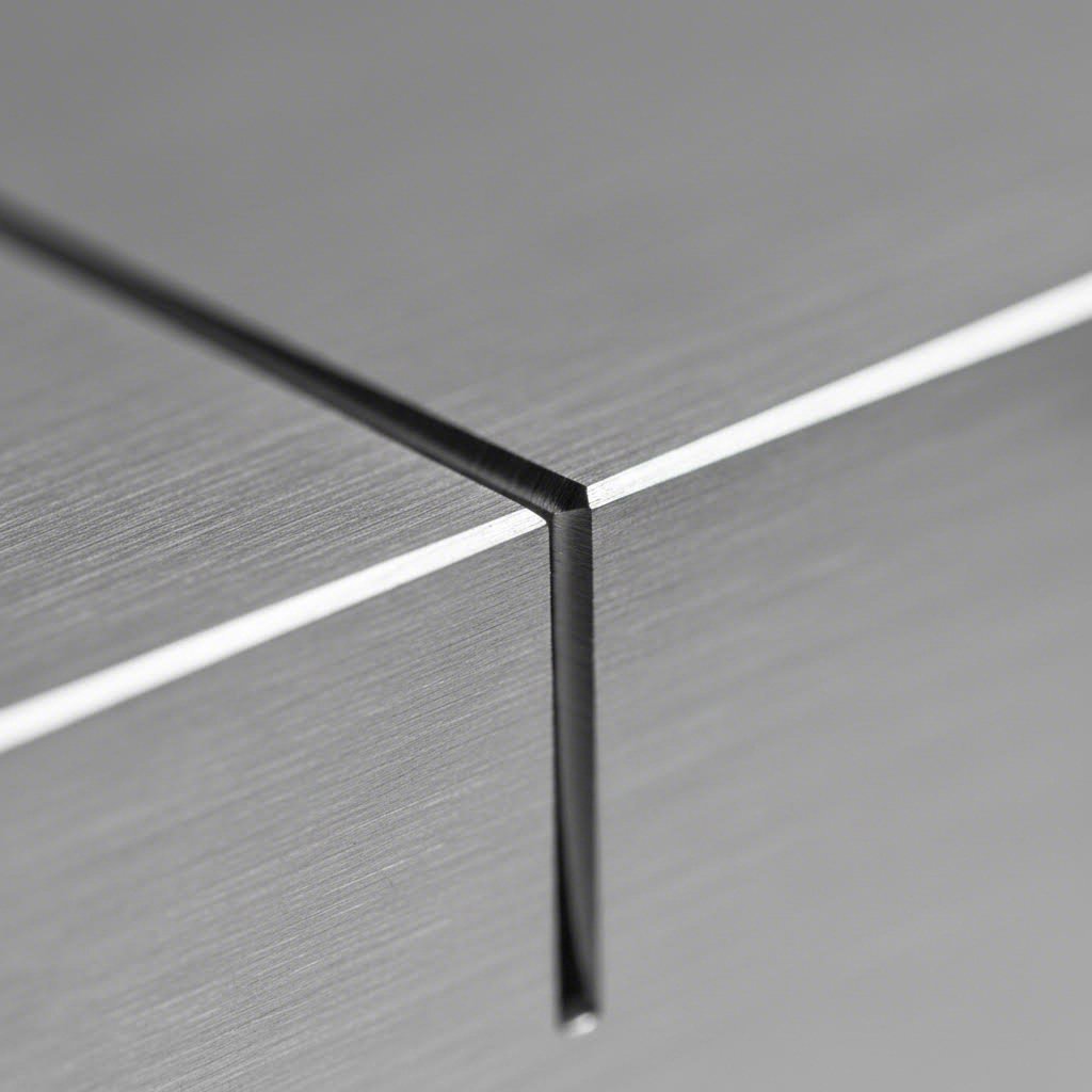
Svaret ligger i et koncept, som mange designere overser: kerf. Denne lille, men kritiske faktor repræsenterer det materiale, der fjernes af laserstrålen under skæringen. Ifølge xTools tekniske guide er kerfbredden ikke bare en skærelinje – den er forskellen mellem en perfekt pasform og et mislykket projekt. Hvis du ignorerer den, fører det til spild af materiale, øgede omkostninger og dimensionelle unøjagtigheder, som kan sabotere hele din produktion.
Beregning af kerfkompensation for præcisionsdele
Tænk på kerf som laserens "bid". Hver gang strålen passerer gennem dit materiale, fordamper den et tyndt metalstrimmel. Dette strimmel – typisk i området 0,15 mm til 0,5 mm afhængigt af dit materiale og lasertype – forsvinder helt. Din CAD-geometri repræsenterer den teoretiske centerlinje for snittet, men den faktiske kant på din del ligger en halv kerfbredde væk på hver side.
Flere faktorer påvirker den nøjagtige kerfbredde, du vil opleve:
- Laserspotstørrelse: Strålens diameter i fokuspunktet bestemmer den mindst mulige kerfbredde. Ifølge xTools forskning er kerfbredden næsten lig med eller let større end laserpletstørrelsen, da dette er det første kontaktsted med materialet
- Materialetykkelse: Laserstråler har en svagt konisk form, hvilket betyder, at de bredder sig, når de trænger længere ned. Tykkere materialer giver bredere kerf ved bundfladen end ved topfladen
- Fokusposition: Præcis overfladefokus skaber smallere kerf, mens dybere fokus inde i materialet øger pletstørrelsen ved overfladen og dermed verbreder snittet
- Materiale type: Metaller viser typisk mindre kerf (0,15 mm til 0,38 mm) i forhold til træ og plast (0,25 mm til 0,51 mm) på grund af højere varmebestandighed
Her er sammenhængen mellem laserstyrke, hastighed og kerf afgørende for dine designvalg. Forskning citeret af xTool viser, at øget laserstyrke udvider kerfbredden, fordi mere energi koncentreres i materialet og dermed fjerner mere materiale. Når skærehastigheden dog øges samtidig med styrken, falder kerfbredden faktisk. Laserstrålen bruger mindre tid på ét sted, så selvom styrken er højere, fjernes der mindre materiale, fordi laseren bevæger sig hurtigere hen over overfladen.
Når du arbejder med en laserudskæringsmaskine til plademetal, opdeles de typiske kerfværdier som følger:
- Fiberlasere på tyndt stål (1-3 mm): 0,15 mm - 0,25 mm kerf
- Fiberlasere på mellemstort stål (3-6 mm): 0,2 mm - 0,3 mm kerf
- CO2-lasere på tykt stål (10 mm+): 0,3 mm - 0,5 mm kerf
- Fiberlasere på aluminium: 0,2 mm - 0,4 mm skærebredde (bredere på grund af varmeledningsevne)
- Fiberlasere på kobber/messing: 0,25 mm - 0,5 mm skærebredde (bredest på grund af refleksionsudfordringer)
Når skærebredde gør eller bryder dit design
At forstå tolerancerne ved laserudskæring hjælper dig med at afgøre, hvornår der skal kompenseres for skærebredde, og hvornår du sikkert kan se bort fra det. Ifølge ADHMT's omfattende tolerancevejledning kan højtkvalitets laserudskæringsmaskiner opretholde tolerancer så stramme som ±0,1 mm, hvor fiberlasere opnår ±0,05 mm eller endnu ±0,025 mm inden for præcisionsplademetalbearbejdning.
Men her er det, de fleste vejledninger glemmer at forklare: tolerance ved laserudskæring afhænger stort set af dine designvalg. Den samme maskine, der opnår en nøjagtighed på ±0,05 mm på 2 mm rustfrit stål, kan måske kun opnå ±0,25 mm på 12 mm plade. Når materialstykkelsen øges, udvides varmepåvirkede zoner, rensning af smeltedross bliver sværere, og den naturlige koniske form af laserstrålen skaber forskelle mellem skærebredde i toppen og i bunden.
Hvornår bør du så anvende kerfkompensation? Overvej disse strategier baseret på din anvendelse:
- Justér baner for stramme tolerancer: Når dine laserudskårne dele skal passe præcist sammen – tænk på sammenføjninger, trykføjninger eller glidebeslag – justér skærebanerne med halvdelen af den forventede kerfbredde. For eksterne dimensioner justerer du udad; for interne funktioner som huller og neder justerer du indad
- Design til nominelle dimensioner for standarddele: For dele med generøse spil eller dele, der vil blive svejst i stedet for mekanisk samlet, giver den naturlige kerf ofte acceptabel resultater uden kompensation. Et 10 mm hul designet til nominel størrelse vil efter skæring måle ca. 10,2–10,3 mm, hvilket kan være fuldstændig acceptabelt for boltspil
- Test med prototyper for kritiske sammensætninger: Når din applikation kræver præcision ud over ±0,1 mm, skal du bestille prøvesnit, inden du går i produktion med større mængder. Mål den faktiske kerf på dit specifikke materiale og laser-kombination, og juster derefter din design. Denne fremgangsmåde er afgørende inden for luft- og rumfart, medicinsk udstyr og automobiler, hvor pasform er vigtig
Typen af snit påvirker også din kompensationsstrategi. Lige snit bevarer en konsekvent kerfbredde, fordi hastighed og effekt forbliver stabile. Krumme linjer kræver, at laseren ændrer retning og nogle gange hastighed, hvilket kan føre til inkonsistenser. Når laseren sænker farten for at navigere en stram kurve, kan den fjerne mere materiale ved det pågældende punkt, hvilket resulterer i en bredere kerf. Design kurver med generøse radier for at minimere dette fænomen
Et sidste overvejelsespunkt: fokuspositionen påvirker delnøjagtigheden markant. Ifølge ADHMT's tekniske analyse hjælper det med at opnå en ensartet skærevide fra top til bund, når fokuspunktet placeres i halvdelen til to tredjedele af materialets tykkelse ved skæring af tykkere plader, hvilket minimerer indfaldende kanter og giver mere lodrette skærekanter. Samtale med din producent om fokusindstillinger, hvis lodrette kantede er vigtigt for din samling.
Nu hvor du har kerfkompensationsstrategierne klar, består næste trin i at forberede dine designfiler til produktion – så din omhyggeligt kompenserede geometri nøjagtigt overføres fra CAD til skæreklar format.
Optimering af designfiler – Fra CAD til produktion
Du har beregnet din skærekompensation, valgt det rigtige materiale og designet funktioner, der opfylder alle minimumskravene. Nu er det afgørende øjeblik: konvertering af dit CAD-design til en produktionsklar fil. Det er dette trin, der driller flest designere, og konsekvenserne varierer fra mindre forsinkelser til fuldstændig afvisning af ordren.
Lyd komplekst? Det behøver det ikke at være. Når du først forstår, hvordan man korrekt klipper laserfilfiler – fra rensning af geometri til formatkonvertering – vil du konsekvent kunne levere filer, som producenterne elsker. Lad os gennemgå hele arbejdsgangen, der omdanner din kreative idé til fejlfrie laserklippede dele.
Fra CAD-skitsse til klar-til-klip-fil
Tænk på filforberedelse som kvalitetskontrol for din design. Hvert problem, du opdager før indsendelse, sparer tid, penge og frustration. Ifølge SendCutSend's preflight-analyse sættes ordrer med filproblemer på pause, hvilket lægger en dag eller mere til den samlede leveringstid. Godt nok? De fleste problemer kan helt undgås med en systematisk tilgang.
Her er trin-for-trin-arbejdsgangen, der sikrer, at dine filer altid består kontrol:
- Designoprettelse med produktion i tankerne: Start dit CAD-arbejde med viden om, at det bliver en laserudskæringsfil. Design den flade, todimensionale side af din del i målestoksforholdet 1:1. Undgå at tilføje perspektivtegninger, mål, noter eller kanter direkte på din skæregeometri. Hvis du har brug for annoteringer, placer dem på separate lag, der ikke eksporteres sammen med dine skærebaner
- Geometrensning og validering: Før du eksporterer, eliminer de skjulte fejl, der forårsager produktionsfejl. Brug din designsoftwares stiværktøjer til at forbinde åbne stier til lukkede former. Slet eventuelle dubletter – disse får laseren til at skære den samme sti to gange, hvilket resulterer i overdreven brænding og spildt maskintid. Fjern skjulte lag, klippe-masks og unødvendige elementer, som kan forvirre skæresoftwaren
- Anvendelse af kerf-kompensation: Anvend de forskydningsberegninger, du fastslog tidligere. For eksterne dimensioner, der kræver tætte pasform, forskyd stierne udad med halvdelen af din forventede kerf-bredde. For interne funktioner, forskydes indad. De fleste CAD-programmer indeholder stiforskydningsfunktioner, der håndterer dette automatisk, så snart du indtaster den korrekte værdi
- Filformatkonvertering: Eksporter din rensede geometri til et format, som din producent accepterer. Gem i de korrekte enheder – typisk tommer eller millimeter – og verificer, at målestokken svarer til din ønskede delstørrelse. De fleste laserskæreserviceydelser accepterer DXF-, DWG-, AI- eller SVG-formater
- Sidste valideringskontrol: Åbn din eksporterede fil i en separat viewer eller importer den igen i dit CAD-program. Bekræft, at alle baner er blevet eksporteret korrekt, dimensionerne svarer til din designhensigt, og at ingen geometri er gået tabt eller blevet beskadiget under konverteringen. Dette sidste trin fanger eventuelle eksportfejl, inden de bliver produktionsproblemer
Forbereder dine designfiler til produktion
Valg af det rigtige filformat påvirker, hvor nøjagtigt dit design overføres til skæreanlægget. Når du vælger designsoftware til laser-skæringsprojekter, skal du forstå styrken ved hvert format:
- DXF (Drawing Exchange Format): Det universelle standardformat for CAD-dataudveksling. Ifølge Fabberz' vejledning i filforberedelse , fungerer DXF sammen med næsten alle laserskæresystemer og CAD-programmer. Det håndterer kompleks geometri godt og bevarer lagorganiseringen. Brug DXF, når du arbejder med AutoCAD, SolidWorks, Fusion 360 eller anden ingeniørfokuseret software
- DWG (AutoCAD-tegning): AutoCAD's oprindelige format tilbyder fremragende præcision og understøtter både 2D- og 3D-geometri. Hvis din producent bruger AutoCAD-baseret nesting-software, importeres DWG-filer ofte renere end konverterede DXF-filer
- AI (Adobe Illustrator): Branchestandard for vektorgrafik og ideel til komplekse kunstneriske designs. Illustrator er fremragende til at håndtere kurver, tekst og lagdelte designs. Sæt din stregbredde til 0,001 tommer og brug RGB-farver til at skelne mellem skærelinjer (rød), svagtningslinjer (blå) og gravurarealer (sort)
- SVG (Scalable Vector Graphics): Et alsidigt, open-source-alternativ til AI-filer. SVG fungerer på tværs af flere platforme og bevarer vektorpræcision. Det er særlig nyttigt, når du samarbejder med designere, der bruger forskellige softwarepakker
Når en laserudskærer skærer metaldele, følger maskinen nøjagtigt dine vektorstier. Det betyder, at hver fejl i din fil direkte oversættes til et problem i din del. Ifølge DXF4You's optimeringsvejledning , overkommplekse eller ikke-optimerede designs forårsager langsommere produktion, øget værktøjsforbrud, nedsat skærepræcision og potentielle sikkerhedsproblemer.
Eliminer almindelige filfejl
Selv erfarne designere støder på disse problemer. Sådan identificerer og retter du dem:
- Åbne stier: Dette sker, når linjesegmenter ikke er forbundet, så de danner lukkede figurer. Laseren har brug for sammenhængende stier for at vide, hvor der skal skæres. I Illustrator kan du bruge Objekt → Sti → Forbind for at lukke huller. I AutoCAD bruger du kommandoen PEDIT til at forbinde linjesegmenter
- Duplikerede linjer: Overlappende geometri får laseren til at skære den samme sti flere gange. Ifølge Fabberz skal du bruge "Forbind"-værktøjet i Illustrator, kommandoen "SelDup" i Rhino 3D eller kommandoen "Overkill" i AutoCAD for at finde og slette dubletter. Du kan spotte dubletter ved unusuelt tykke linjer i dit forhåndsvisning
- Ukorrekt lagorganisering: At blande skærebaner med gravurarealer eller annotationer forvirrer skæresoftware. Opret separate lag for hver operationstype og slet eller skjul ikke-væsentlige lag før eksport
- Tekst ikke konverteret til konturer: Skrifttyper kan muligvis ikke overføres mellem systemer, hvilket får din tekst til at vises forkert eller helt forsvinde. I Illustrator skal du markere teksten og bruge Type → Omdan til konturer (Shift + Cmd/Ctrl + O), inden du eksporterer
- Forudindstillede filer med flere dele: Selvom det ser ud til at være effektivt at placere flere dele i én fil, pointerer SendCutSend, at forudindstillede filer langsommeliggør produktionen, forhindrer mængderabatter og giver et forkert billede af de reelle delstørrelser. Upload hver unik del som en separat fil
Eksportindstillinger, der påvirker skære kvalitet
Dine eksportindstillinger er lige så vigtige som din designgeometri. Følg disse retningslinjer for rene filexporteringer:
- Indstil dokuments enheder, så de matcher fabrikantens præference (typisk tommer for amerikanske værksteder, millimeter for internationale)
- Brug RGB-farvetilstand, ikke CMYK, for korrekt genkendelse af linjetypen
- Sørg for en 0,25" kant rundt om dit motiv som beskæringsområde
- Sørg for, at din tegneblok eller arbejdsplads svarer til dine materialeafmålinger
- Hold dele mindst 0,125" fra hinanden, når de anbringes sammen, med justering efter materialetykkelse
Hvis du oplever vedvarende eksporteringsproblemer, kan du overveje at bruge QCAD – et gratis, open-source DXF-redigeringsprogram, der anbefales til kontrol af filer. Det giver dig mulighed for at se præcis, hvad laserskæresoftwaren vil se, og manuelt rette eventuelle resterende problemer.
Når du først har etableret en konsekvent rutine for filforberedelse, bliver det naturligt at designe til laserskæring. Når du har rene og korrekt formaterede filer klar til indsendelse, flytter din fokus sig mod at optimere disse designs ud fra omkostningseffektivitet – så dine dele ikke blot er fremstillelige, men også økonomiske at producere.
Omkostningsdrevne designstrategier og optimering af placering
Din designfil er ren, din geometri er valideret, og din kerf-kompensation er indstillet. Men her er et spørgsmål, der skiller gode designere fra de allerbedste: hvor meget vil det egentlig koste at producere denne del? Hvert eneste linjestykke du tegner, hvert hul du stanser, og hver detalje du tilføjer, går direkte ud over maskintid, materialeforbrug og sidst men ikke mindst, din bundlinje.
Forholdet mellem designvalg og produktionsomkostninger er ikke altid åbenlyst. En lille ændring af hjørneradius kan spare sekunder på hver skæring. Omplacering af nogle få funktioner kan reducere affaldet med 15 %. Disse små optimeringer summer sig hurtigt, især når du bestiller hundredvis eller tusindvis af dele. Lad os se på, hvordan intelligente designvalg hjælper dig med at kontrollere omkostningerne uden at gå på kompromis med kvaliteten.
Designvalg, der reducerer skæreomkostninger
Når en laserskæremaskine forarbejder din komponent, er der to primære faktorer, der bestemmer omkostningerne: maskinetid og materialeforbrug. At forstå, hvordan din konstruktion påvirker begge faktorer, giver dig styrke til at kontrollere dine produktionsomkostninger.
Skærestiens længde er måske den mest direkte omkostningsdrevende faktor. Ifølge Vyteks vejledning i omkostningsoptimering kræver komplekse geometrier med indviklede detaljer mere præcis laserstyring og længere skæretider, hvilket hurtigt opsamler omkostninger. Hvert millimeter af skæresti repræsenterer tid på maskinen, og maskinetid koster penge.
Overvej to versioner af samme beslagsdesign. Version A har dekorative ornamenter, stramme indre hjørner og seks små monteringshuller. Version B opnår samme strukturelle funktion med rene lige kanter, generøse hårnålekurver og fire lidt større huller. Det andet design kan muligvis skæres 40 % hurtigere, mens det bevarer identisk funktionalitet.
Her er nogle designstrategier, der reducerer skæreomkostningerne uden at kompromittere din komponents formål:
- Minimer gennemborepunkter: Hver gang laseren starter et nyt snit, skal den gennembore materialet – en proces, der tager længere tid end kontinuerlig skæring. Design dele med færre separate indvendige udsparinger, når det er muligt. Kombiner flere små huller til forlængede spalter, hvis dit anvendelsesområde tillader det
- Reducer indviklede detaljer, hvor det ikke er nødvendigt: Spørg dig selv, om hver kurve og kontur har et funktionelt formål. Afrundede hjørner skæres hurtigere end skarpe indvendige vinkler, og simple former behandles hurtigere end komplekse silhuetter. Ifølge Vytek kan undgåelse af skarpe indvendige hjørner, minimering af små indviklede snit og brug af færre kurver resultere i betydelige besparelser
- Udformning til standard pladestørrelser: En laser-skellemetalsskære-maskine arbejder med standardmateriale-dimensioner. Når dine dele ikke passer effektivt på almindelige pladestørrelser, betaler du for spildt materiale. Design dele, der placeres rentabelt på 48" x 96" eller 60" x 120" plader, når det er muligt
- Simplificér krav til kantkvalitet: Ikke hver kant behøver at være perfekt. Ifølge branchens retningslinjer kræver det ofte høj kvalitet af kanter, at man formindsker laserenes hastighed eller bruger mere effekt, hvilket begge øger omkostningerne. Angiv standard kantkvalitet til skjulte overflader og gem premium finish til synlige områder
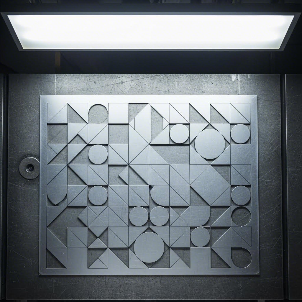
Optimering af pladeudnyttelse gennem smart design
Materialomkostninger overstiger ofte maskinetidsomkostninger, hvilket gør effektiv pladeudnyttelse afgørende for at holde budgettet under kontrol. Her bliver nesting – den strategiske placering af dele på materialeplader – dit mest effektive værktøj til omkostningsreduktion.
Ifølge Boss Lasers omfattende nestingvejledning , effektiv nesting kan reducere materialeaffald med 10-20 %. På dyre materialer som rustfrit stål eller aluminium udgør disse besparelser tusindvis af dollars over en produktion
Overvej dette eksempel fra Boss Lasers analyse: Et produktionsfirma havde brug for 500 specialfremstillede metaldele på gennemsnitligt 100 kvadrattommer hver, udskåret fra plader á 1.000 kvadrattommer til $150 pr. plade. Uden nesting-software kunne manuelt layout kun rumme 8 dele pr. plade, hvilket krævede 63 plader og $9.450 i materialeomkostninger. Med optimeret nesting kunne 12 dele placeres pr. plade, hvilket reducerede behovet til 42 plader og $6.300 i materialeomkostninger – et besparelse alene på materialer på $3.150.
Din rolle som designer påvirker direkte nesting-effektiviteten. Sådan designer du dele, der nestes optimalt:
- Gruppér dele til effektiv nesting: Når du designer flere komponenter til en samling, skal du overveje, hvordan de passer sammen på en plade. Komplementære former, der tessellerer – som puslespilsbrikker – udnytter materialet bedst muligt. En buet udsparing i én del kan fx perfekt rumme en afrundet funktion fra en anden
- Undgå ulige mål: Dele med usædvanlige proportioner skaber ujævne mellemrum, når de placeres inden i hinanden. Design med almindelige dimensioner i tankerne, og afrund delstørrelser til værdier, der går op i standardpladestørrelser
- Overvej rotationsmuligheder: Dele, der kan roteres 90° eller 180° under indlægning, giver flere muligheder for placering. Hvis kornretningen ikke har betydning for dit anvendelsesområde, skal du enten designe symmetriske dele eller notere, at rotation er tilladt
- Afstand mellem geometrier: Ifølge Makerverse's designvejledninger , afstanden mellem skæregeometrier bør være mindst dobbelt så stor som pladetykkelsen for at undgå deformation. Denne minimale afstand sikrer også rene snit mellem indlagte dele
Moderne laserudskæringsprocesser til plademetal er afhængige af sofistikerede indlægningsprogrammer, der automatisk optimerer placeringen af dele. Programmet kan dog kun arbejde med den geometri, du leverer. Dele, der er designet med hensyn til indlægning, opnår konsekvent bedre materialeudnyttelse end dele, der er designet isoleret.
Prototype vs. produktion: Forskellige mål for optimering
Her er hvad mange designere overser: optimale designvalg adskiller sig betydeligt mellem prototyper og fuld produktion. Prioriteringerne ændrer sig, og din designtilgang bør ændre sig tilsvarende.
Under udvikling af prototyper er dit primære mål at validere designet hurtigt og omkostningseffektivt. Materialeffektivitet er mindre vigtig, når du bestiller fem dele i stedet for fem hundrede. Fokuser på:
- Mulighed for hurtig iteration – designfunktioner, der er nemme at ændre
- Afprøvning af pasform og funktion, inden du fastlægger optimeret geometri
- Anvendelse af let tilgængelige standardmaterialer i stedet for specifikke legeringer
- Accept af standard kantkvalitet for at minimere leveringstid
Ved produktion betaler hver eneste optimering sig. Ifølge Vyteks produktionsvejledning er flad laserudskæring typisk mere effektiv, når den udføres i partier. Opsætning af en laserudskærer tager tid, så større mængder produceret i én gang reducerer hyppige maskintilpasninger, sparer opsætningstid og nedsætter omkostningerne pr. del.
Produktionsfokuseret designoptimering omfatter:
- Maksimering af udnyttelseseffektivitet gennem bevidste geometrivalg
- Minimering af skæresti-længde ved at fjerne ikke-funktionelle detaljer
- Specificering af kantkvalitetsniveauer baseret på hver overflades synlighed og funktion
- Konsolidering af ordrer for at udnytte batchprocesseringseffektiviteten
Overgangen fra prototype til produktion giver en ideel mulighed for at genoverveje dit design med henblik på omkostningsoptimering. Funktioner, der var hensigtsmæssige til hurtig validering, kan have brug for finjustering, inden der skalerer op. Tag dig tid til at analysere skærestier, vurdere materialeudnyttelse og fjerne enhver geometri, der ikke tjener et klart funktionelt formål.
Med omkostningsoptimerede designstrategier på plads er du godt rustet til at undgå de almindelige fejl, der fører til produktionsfejl og kvalitetsproblemer — det emne, vi vil tage fat i næste gang.
Undgå designfejl og kvalitetsproblemer
Du har optimeret din design til at være omkostningseffektiv, forberedt fejlfrie filer og valgt det perfekte materiale. Så ankommer dine dele med buede kanter, misfarvede overflader eller detaljer, der simpelthen ikke er skåret rent igennem. Hvad gik galt? At forstå, hvorfor dele mislykkes – og hvordan dine designvalg direkte forårsager eller forhindrer disse fejl – adskiller frustrerende omarbejdning fra succes ved første forsøg.
Stålskæring med laser og laserskæring af metalplader følger forudsigelige fysiske principper. Når du forstår sammenhængen mellem designparametre og fejlmåder, får du mulighed for at forhindre problemer, inden de opstår. Lad os undersøge de mest almindelige kvalitetsproblemer og de designbeslutninger, der forårsager dem.
Almindelige designfejl og hvordan man undgår dem
Enhver producent har en række advarselshistorier om designs, der så perfekte ud på skærmen, men dramatisk brød sammen i produktionen. Ifølge API's omfattende fejlanalyse skyldes de fleste problemer med skære kvalitet et begrænset antal undgåelige design- og parameterrelaterede problemer.
Her er de designfejl, der forårsager de største produktionsproblemer:
- Funktioner placeret for tæt på kanter Ifølge Makerverse's designvejledninger , huller placeret for tæt på kanten har en højere risiko for revner eller deformation, især hvis emnet senere gennemgår formning. Sørg for mindst 1,5 gange materialetykkelsen mellem enhver funktion og kanten af pladen
- Utilstrækkelige fælgeforbindelser: Fælger holder emner på plads under skæring og forhindrer, at de flytter sig og forårsager unøjagtige skær. Design fælger med mindst 2 mm bredde for tynde materialer og øg proportionalt med tykkelsen. Svage fælger knækker for tidligt, hvilket tillader emner at bevæge sig under skæringen
- Skarpe indvendige hjørner, der forårsager spændingskoncentration: Laseren skal bremse markant op for at navigere skarpe hjørner, hvilket koncentrerer varme og ofte resulterer i ufuldstændig eller dårlig skæring. Ifølge Eagle Metalcrafts designråd, skal man bruge en ensartet indvendig bueradius – ideelt set svarende til materialetykkelsen – for at forbedre værktøjseffektiviteten og justeringen af emnerne
- Tekststørrelse under minimale grænseværdier: Små tekster og fin detaljering kræver præcis laserstyring. Tegn mindre end 2 mm i højden på tynde materialer mister ofte læsbarheden eller brænder helt igennem. Når gravering er nødvendig, skal du bruge fed, serif-fri skrifttyper og kontrollere minimumslinjebreddener hos din producent
- For tæt placering af geometri: Ifølge Makerverse forhindres deformation ved at holde en afstand på mindst dobbelt pladetykkelsen mellem skæregeometrier. Tættere afstande får tilstødende snit til at påvirke hinanden termisk, hvilket forvrider begge elementer
Hvorfor dele mislykkes og hvad din konstruktion kan gøre for at forhindre det
Ud over geometriske fejl hjælper forståelse af fysikken bag laserskæring af stålplader og andre materialer dig med at forudse og forhindre kvalitetsnedbrydning. Tre fejlmåder fortjener særlig opmærksomhed: varme-påvirkede zoner, forvrængning og kantkvalitetsproblemer.
Varme-påvirkede zoner og termisk skade
Hvert laserudskæring skaber en varmepåvirket zone (HAZ) – et område hvor metallets egenskaber ændres på grund af termisk udsættelse. Ifølge API's tekniske vejledning kan HAZ forringe et færdigt produkts ydeevne ved at øge hårdheden eller mindske ductiliteten i det pågældende område.
Din design påvirker HAZ's alvorlighed på flere måder:
- Intrikate detaljer med mange tætliggende snit akkumulerer varme, hvilket udvider den påvirkede zone
- Tykke materialer kræver langsommere skærehastigheder, hvilket øger den termiske udsættelse
- Tætte klynger af funktioner forhindrer tilstrækkelig afkøling mellem snit
For at minimere HAZ bør du sprede funktioner ud i din design i stedet for at gruppere dem. Sørg for mindst 3 mm mellem parallelle skærelinjer på materialer over 3 mm tykke. For kritiske anvendelser, hvor minimale egenskabsændringer er nødvendige, bed din producent om at bruge nitrogen som assistentgas – det giver renere snit med mindre oxidation og mindre varmepåvirkede zoner.
Vridning i tynde materialer
Tyndplader udgør en særlig udfordring. Ifølge API's fejlanalyse kan en højtydende lasers intense varmetilførsel forvrænge eller bukke tynde materialer, hvilket påvirker deres udseende og funktion. Materialer under 1 mm tykkelse er især sårbare.
Konstruktionsstrategier, der reducerer bøjning, inkluderer:
- Tilføjelse af midlertidige stivningsfodder, der forbinder til den omgivende plade og fjernes efter skæring
- Udvikling af dele med afbalanceret geometri – asymmetriske former bukker mere end symmetriske
- Undgå store åbne områder omgivet af skæringer, som frigiver indre spændinger uregelmæssigt
- Angivelse af pulserede skæremetoder til meget tynde materialer, hvilket reducerer kontinuerlig varmetilførsel
Ifølge Eagle Metalcraft sikrer flade plader præcise resultater ved laserskæring af stål. Forvredet eller buket metal fører til justeringsproblemer og inkonsistente skæringer. Hvis du starter med materiale, der ikke er helt fladt, skal du forvente forøget forvrængning efter skæring.
Deteriorering af kantkvalitet
Kantkvalitetsforventninger bør være i overensstemmelse med dine designvalg og anvendelseskrav. Ifølge API's kvalitetsanalyse skyldes ru eller ujævne kanter flere faktorer:
- Forkert fokusposition: Laserstrålen kræver et skarpt fokuspunkt og lav divergens for at opnå præcise snit. Designs med varierende tykkelse eller betydelige højdeforandringer gør det sværere at optimere fokus
- Forkert gastryk: Ændringer i gasspænding medfører inkonsistent skære kvalitet og uregelmæssigheder. Selvom dette er en maskineparameter, påvirker dit materialevalg og materialstykkelse de optimale trykindstillinger
- Dros og slagger: adhæsion Smeltet materiale, der stivner på skæreoverflader, skaber ru bundkanter. Ifølge API resulterer genopsmeltning eller genstivning af materiale langs skærekanter i ujævne overflader
- Oxidation og misfarvning: Det kraftige lys, som en laser udsender, kan oxidere eller misfarve skærekanter, hvilket påvirker overfladekvalitet og udseende. Designs, der kræver fejlfrie kanter, bør angive brug af nitrogen til understøttende skæring
Kantkvalitetsforventninger efter anvendelse
Ikke alle dele kræver perfekte kanter. At sætte realistiske forventninger baseret på din anvendelse forhindrer over-specifikation og unødvendige omkostninger:
| Anvendelsestype | Acceptable kantegenskaber | Designovervejelser |
|---|---|---|
| Strukturelle/skjulte komponenter | Let oxidation, mindre slaggerester, let ruhed | Standard skæreparametre er acceptabelle; fokus på dimensionel nøjagtighed |
| Synlige dekorative dele | Rejne kanter, minimal misfarvning | Specificer kvælstofhjælp; indregne kantbehandling i tidsplanen |
| Præcisionsmekaniske samlinger | Uden burr, konsekvent snitsbredde, lodrette kanter | Små tolerancer kræver langsommere hastigheder; tilføj tillæg til efterbehandling |
| Anvendelser til føde- og medicinalkvalitet | Glat, uden sprækker hvor forurening kan ophobes | Efterbehandling kan være nødvendig; design med generøse radier |
Ifølge Eagle Metalcrafts kvalitetsvejledning opnår de fleste laserudskæringer en nøjagtighed inden for ±0,1 mm. Små tolerancer bør markeres tidligt, så producenterne kan justere deres proces tilsvarende. Når din applikation kræver bedre kantkvalitet end standard, skal dette krav kommunikeres tydeligt – og du må forvente justeret pris og leveringstid.
At forstå fejlmåder ændrer din tilgang til design af metal laserudskæring. I stedet for først at opdage problemer efter produktionen, kan du fra starten designe dem ud af dit produkt. Når kvalitetsovervejelser er dækket, er næste skridt at integrere dit laserudskæringsdesign i de efterfølgende produktionsprocesser – så dine dele fungerer problemfrit gennem bøjning, svejsning og endelig samling.
Design til komplette produktionsarbejdsgange
Dine laserudskårne dele ser perfekte ud, når de kommer ud af maskinen. Rene kanter, præcise mål, hver enkelt detalje nøjagtigt, hvor du har designet den. Derefter går delene til bøjningspressen – og pludselig passer intet sammen. Huller, der skal modtage samlingselementer, sidder nu forkert placeret. Flinger, der skulle ligge tæt op ad hinanden, viser synlige sprækker. Hvad gik galt?
Forkoblingen mellem laserudskæring og efterfølgende operationer overrasker mange konstruktører. Laserudskæring i plademetal og bøjning er ikke isolerede processer – de er forbundne trin i en produktionsproces, hvor hver enkelt handling påvirker de andre. At forstå disse relationer ændrer din tilgang fra at designe dele til at designe komplette produktionsresultater.
Design til bøjning og sekundære operationer
Når du designer en del, der skal bøjes efter laserudskæring, designer du ikke kun en flad geometri. Du forudser, hvordan det flade mønster vil omdannes til en tredimensional form. Ifølge Geomiqs vejledning i plademetaludformning , flere kritiske begreber styrer denne transformation:
- Bøjelængde: Længden af den neutrale akse mellem bøjelinier—essentielt bueafsnittets længde for bøjningen selv. Denne værdi, lagt til dine flanjlængder, svarer til den totale flade længde, du skal skære
- K-faktor: Forholdet mellem placeringen af den neutrale akse og materialetykkelsen. Ifølge Geomiq afhænger K-faktoren af materiale, bøjeproces og bøjningsvinkel og ligger typisk mellem 0,25 og 0,50. Det er afgørende at have denne værdi korrekt indstillet i din CAD-software for nøjagtige flade mønstre
- Bøjeradius: Afstanden fra bøjeaksen til materialets inderside. Ifølge Eagle Metalcrafts konstruktionsvejledninger forbedrer anvendelse af en ensartet indre bøjeradius—ideelt set svarende til materialetykkelsen—værktøjseffektiviteten og delenes justering
Hvorfor er disse beregninger vigtige for din laserskæredesign? Fordi det flade mønster, du indsender til skæring, skal tage højde for materialeadfærden under bøjning. Skærer du den forkerte flade længde, vil din færdige del ikke overholde specifikationerne.
Placering af huller i forhold til buer
Her fejler mange designs: at placere huller for tæt på bøjningslinjer. Når metal bukkes, strækker materialet sig på ydersiden af radius og komprimeres på indersiden. Huller placeret i denne deformationssone bliver forvrænget – runde huller bliver ovale, og præcise tolerancer forsvinder.
Ifølge Eagle Metalcraft medfører placering af huller for tæt på bøjninger deformation. De anbefaler at efterlade mindst materialets tykkelse – helst 1,5 til 2 gange tykkelsen – mellem hullet og bøjningslinjen. Ligeledes anbefaler Gasparinis omfattende vejledning for bøjning at fastholde tilstrækkelige afstande (mindst bøjningsradius plus 2 gange tykkelsen) mellem bøjningslinjen og huller, kanter, lameller og gevind.
Overvej dette praktiske eksempel: Du designer et ophængsfæste i 2 mm stål med en 90-graders bøjning. Dine monteringshuller skal forblive runde og korrekt placerede efter bøjningen. Ved brug af den anbefalede minimale afstand, placerer du hulcentrene mindst 4 mm (2 × tykkelsen) fra bøjningslinjen. For kritiske anvendelser øges denne afstand til 6 mm (3 × tykkelsen) for at sikre helt ingen deformation.
Hjørneudskæringer og bøjningsudskæringer
Når to bøjninger mødes i et hjørne, har materialet ingen sted at gå hen. Uden korrekte udskæringer revner eller bukker metallet, eller der opnås uforudsigelige resultater. Ifølge Gasparini skal du indsætte de nødvendige bøjningsudskæringer i din tegning for at undgå revner og sprog. Glem ikke hjørneudskæringer ved skærende bøjninger.
Din laserudskæringsfil bør omfatte disse udskæringer som del af geometrien. Almindelige typer af udskæringer inkluderer:
- Runde udskæringer: Cirkulære udskæringer ved bøjningspunkter, som fordeler spænding jævnt
- Firkantede udskæringer: Rektangulære notcher, som giver plads til værktøjet
- Benformede reliefmønstre: Udvidede reliefmønstre til materialer, der er udsat for revnedannelse
Fra laserskæring til færdig samling
Laserskæring inden for metalbearbejdning går ud over blot skæring og bøjning. Ofte fortsætter dine dele med svejsning, samling, overfladebehandling og endelig montage. Hver efterfølgende proces stiller specifikke krav til din oprindelige laserskæringsdesign.
Bevidsthed om materialeets retning
Plademetal er anisotropt – dets egenskaber varierer afhængigt af retningen. Ifølge Gasparinis produktionsvejledning ændrer materialets opførsel sig afhængigt af rulle- eller trækretningen. Dette påvirker kvaliteten af bøjningen betydeligt.
Overvej følgende retningslinjer for materialeets retning i dit laserskæringsdesign:
- Skær alle dele i samme orientering: Undgå nesting med variabel orientering. Du kan spare plademetal ved at placere et ekstra stykke, men du risikerer at spilde dele, fordi du ikke opnår den rigtige vinkel ved bøjning
- Opdel dele efter placering på pladen: Indre spændinger ændrer sig mellem centrum og kanter af plader på grund af rullebelastninger. Gruppér dele i overensstemmelse hermed
- Bland ikke batche sammen: Ifølge Gasparini betyder forskelle mellem støbninger varierende hårdhed og elasticitet, hvilket påvirker det endelige resultat
Planlægning af adgang til svejsning
Når dine laserudskårne dele skal svejses sammen til samlingselementer, skal din konstruktion tage højde for selve svejseprocessen:
- Sikr tilstrækkelig frihøjde for svejseelektroder eller svejsetråd
- Indtegn samleforskel (faser, riller) i dit flade mønster, når det er muligt
- Tag højde for svejsedistortion og planlæg efterbearbejdning med maskin, hvis stramme tolerancer kræves
- Placér svejsninger væk fra områder med høj belastning og synlige overflader
Design af samlingsfunktioner
Smart samlede funktioner integreret i din laserskæredesign reducerer arbejdsindsatsen nedstrøms og forbedrer konsistensen:
- Justeringstabs og -nødder: Selvcentrerende funktioner, der placerer dele korrekt under samling
- Pilot huller: For små huller, der fører boringer eller gengangsoperationer
- Bøjelinjemarkeringer: Ifølge Gasparini kan du få markeringer anbragt på kanter ved hjælp af laseren for at angive bøjningspositioner. De bør helst vende udad for at undgå revner
- Delen identifikation: Ifølge Eagle Metalcraft kan tilvirkerne ætse delnumre, logoer eller guider på dele – blot inkludér detaljerne i din fil
Overvejelser om mikroforbindelser
Når CNC-lasermetalskæring behandler små dele, forhindrer mikroforbindelser (små flikker, der forbinder delene med pladen) stykker i at falde eller tippe. Disse flikker påvirker dog efterfølgende operationer. Ifølge Gasparini efterlader mikroforbindelser små spidser på kanten, hvilket kan gøre det vanskeligt at placere delen korrekt op ad bagstopfingre under bøjning. Design mikroforbindelser på steder, hvor de ikke forstyrrer efterfølgende operationer.
Brobygning mellem design og komplet fremstilling
At håndtere overgangen fra laserudskæringsdesign til komplet metalbearbejdning kræver enten dyb produktionserfaring eller den rigtige produktionspartner. Det er her, omfattende Design for Manufacturing (DFM)-support bliver uvurderlig.
Producenter som Shaoyi (Ningbo) Metal Technology dække dette hul ved at levere integreret laserskæring af metal med fuld DFM-understøttelse. Deres tilgang hjælper designere med at optimere både skæring og efterfølgende forming eller samleoperationer – og opdage potentielle problemer, inden de bliver produktionsproblemer. Til designiteration giver deres 12-timers tilbudsomløbstid mulighed for hurtig validering af designændringer uden lange forsinkelser.
Når du arbejder med en fabrikeringspartner, skal du kommunikere hele din produktionsproces fra starten. Del ikke kun dine filer til laserskæring, men også oplysninger om planlagte bøjninger, samlemetoder og krav til den endelige anvendelse. Denne helhedsorienterede tilgang forhindrer brudflader mellem operationer, hvilket er årsag til mange kvalitetsproblemer.
Når dit design er optimeret til hele produktionsprocessen – fra laserskæring gennem bøjning, svejsning og samling – er du klar til at sætte din viden i handling med en omfattende tjekliste og klare næste trin til produktionen.
Sæt din viden om metal-laserudskæringsdesign i praksis
Du har absorberet meget information om laserudskårne metaldesign – fra kerf-kompensation og materialevalg til filforberedelse og overvejelser vedrørende efterfølgende fremstilling. Men viden uden handling forbliver blot teori. Den reelle værdi opstår, når du anvender disse principper på dit næste projekt.
Kan du udføre metaludskæring med en laserudskæringsmaskine og opnå professionelle resultater allerede første gang? Absolut – hvis du tilgangen til produktionen med en systematisk valideringsproces. Forskellen mellem designere, der konsekvent lykkes, og dem, der kæmper, skyldes ofte én ting: en pålidelig tjekliste før indsendelse, der opdager problemer, inden de bliver dyre fejl.
Din tjekliste for designoptimering
Før du indsender et design til din fremstiller, gennemgå denne omfattende tjekliste. Ifølge Impact Fab's designvejledning , kræver perfektionering af dit design tid og opmærksomhed på detaljer, men hvis det udføres korrekt, kan resultaterne være uvurderlige.
Geometrivalidation
- Alle stier er lukkede og forbundne – ingen åbne endepunkter eller huller
- Dubletterede linjer fjernet ved hjælp af softwarens rengøringsværktøjer
- Minimumsdiameter for huller opfylder eller overstiger materialetykkelsen
- Indvendige hjørner inkluderer passende afrundingsradier (minimum halvdelen af materialetykkelsen)
- Elementer har tilstrækkelig afstand til pladens kanter (minimum 1,5× tykkelsen)
- Afstanden mellem tilstødende elementer er mindst 2× materialetykkelsen
- Tekst konverteret til konturer med minimum 2 mm bogstavshøjde
- Bøjninger og hjørneudskæringer inkluderet for dele, der kræver formning
Tolerancesverifikation
- Kerf-kompensation korrekt anvendt for præcisionspasform
- Kritiske dimensioner markeret for fabrikantens opmærksomhed
- Toleransekrav afstemt med laserens evner (±0,1 mm standard, ±0,05 mm præcision)
- Hullets placering verificeret i forhold til bøjeningslinjer (minimum 2× materialetykkelsen)
- Samleinterfaces kontrolleret i henhold til specifikationer for sammenføjede dele
Bekræftelse af filformat
- Fil gemt i accepteret format (DXF, DWG, AI eller SVG)
- Dokumentenheder matcher fabrikantens krav (tommer eller millimeter)
- Skala verificeret til 1:1 – delenes dimensioner svarer til den ønskede produktionsstørrelse
- Linjetykkelse sat til hairline (0,001" eller 0,072 pt)
- Farvemodus sat til RGB for korrekt genkendelse af linjetypen
- Lag organiseret med skærebaner adskilt fra annoteringer
- Ingen skjulte lag, klippeklip eller unødige elementer
Materiale specificering
- Materialetype tydeligt specificeret (legeringsgrad, herdetilstand)
- Materialetykkelse bekræftet og dokumenteret
- Kornretning krav noteret, hvis relevant
- Overfladebehandlingsforventninger kommunikeret
- Krav til kantkvalitet specificeret efter funktion eller overflade
Få dine designs fra koncept til skæring
Nu hvor din tjekliste er færdig, er du klar til at gå videre. Men her er en princip, der skiller succesfulde projekter fra kostbare fejl: valider, inden du forpligter dig.
Ifølge Impact Fab er det vigtigt at arbejde med en udskærer, der vil tage sig tid til at drøfte dit projekt detaljeret med dig. Når det gælder dit laserskæringsprojekt, er der for mange mulige negative udfald til, at man kan overlade noget til tilfældighederne.
Nøgleudformningsprincipper for succes
Når du går fra idéer om laserskæring til produktionsrealitet, skal du huske disse grundlæggende principper:
- Udform med fremstillingen i tankerne: Hvert CAD-valg påvirker produktionsresultaterne. Tænk som en fremstiller, mens du udformer
- Tilpas din udformning til din lasersystemteknologi: Fiberlasere, CO2-lasere og Nd:YAG-systemer har forskellige muligheder – optimer derfor tilsvarende
- Respekter materialernes egenskaber: Reflekterende metaller som aluminium og kobber kræver andre fremgangsmåder end stål
- Tag hensyn til skærespalten konsekvent: Anvend kompensation, hvor præcision er afgørende; afprøv kritiske pasforme med prototyper
- Optimer for omkostninger uden at ofre funktion: Reducer skærestiens længde, minimer gennemborede punkter og design til effektiv indstilling
- Planlæg for hele arbejdsgangen: Overvej krav til bøjning, svejsning og samling allerede fra start
Prototyper før produktion
For projekter hvor præcision er afgørende – chassisdele, ophængsfæste, strukturelle samlinger – giver prototyper uvurderlig validering. Test af din konstruktion med faktiske dele afslører problemer, som kun CAD-analyse ikke kan opdage.
Shaoyi (Ningbo) Metal Technology tilbyder 5-dages hurtig prototypering, der tillader dig at validere konstruktioner inden du går i produktion. Deres IATF 16949-certificerede kvalitet sikrer bilindustrins præcision for kritiske komponenter, mens omfattende DFM-understøttelse hjælper med at optimere din konstruktion både til skæring og efterfølgende operationer. Denne kombination af hastighed og ekspertise gør prototypering praktisk mulig, selv med meget stramme udviklingstidshorisonter.
Uanset om du er en amatør, der udforsker idéer til laserskærere, eller en professionel ingeniør, der udvikler produktionskomponenter, følger vejen til fejlfrie resultater den samme retning: Forstå teknologien, respekter materialerne, forbered dine filer omhyggeligt og valider inden du skalerer op. Anvend disse principper konsekvent, og du vil omdannes fra en, der indsender design, til en, der leverer fremstillingssucces.
Ofte stillede spørgsmål om design til metalskæring med laser
1. Kan vi lave metalskæring med laser?
Ja, laserskæring er en af de mest præcise og effektive metoder til skæring af metal. En fokuseret laserstråle genererer intens varme, der fordamper materiale langs programmerede stier og skaber nøjagtige skæringer i stål, aluminium, rustfrit stål, kobber og messing. Fibre-lasere er fremragende til skæring af tynde til mellemstore metaller og reflekterende materialer, mens CO2-lasere effektivt kan håndtere tykkere stålblade. For optimale resultater skal din design tage højde for materialeegenskaber, kerfbredde og minimumsfeaturestørrelser, der er specifikke for hver metalletype.
hvor tyk stål kan en 1000 W laser skære igennem?
En 1000 W fiberlaser kan typisk skære op til 5 mm rustfrit stål med god kantkvalitet. Til tykkere materialer kræves højere effektmaskiner – 2000 W lasere håndterer 8-10 mm, mens systemer på 3000 W+ kan bearbejde 12-20 mm afhængigt af indstillingerne for skære kvalitet. Når der designes til tykt stål, bør du øge minimale detaljestørrelser, sikre bredere afstand mellem skæringer og forvente større kerfbredder. CO2-lasere med ilttilførsel kan skære plader op til 100 mm tykke, selvom kantkvalitet og præcision falder med stigende tykkelse.
3. Hvilket materiale bør du aldrig skære i laserudskæreren?
Undgå at laserskære materialer, der udvikler toksiske dampe eller beskadiger udstyr. Skær aldrig PVC (polyvinylchlorid), da det udvikler chlor- og saltsyre. Læder med chrom (VI), kulfibre og polycarbonat er ligeledes usikkert. Når det gælder metaller, er de fleste laserkompatible, men stærkt reflekterende materialer som poleret kobber og messing kræver fiberlasere med passende bølgelængder for at forhindre stråle-refleksion, der kan beskadige maskinen. Kontroller altid materiale-sikkerheden hos din producent, inden du skærer.
4. Hvilket filformat er bedst til laserskæring af metaldesign?
DXF (Drawing Exchange Format) er standarden for laserudskæring og kompatibel med næsten alle CAD-programmer og skæresystemer. DWG fungerer godt i arbejdsgange baseret på AutoCAD, mens AI-filer (Adobe Illustrator) er fremragende til komplekse kunstneriske designs. Uanset format skal du sikre, at alle stier er lukkede, dubletterede linjer er fjernet, tekst er konverteret til omrids, og dokumentenheder svarer til din producents præference. Rene, korrekt skalerede filer i målestoksforholdet 1:1 undgår produktionsforsinkelser og afvisningsmeddelelser.
5. Hvordan tager jeg højde for kerfbredde i mit laserudskæringsdesign?
Kerf—materialet fjernet af laserstrålen—varierer typisk fra 0,15 mm til 0,5 mm afhængigt af materialetype, tykkelse og laserteknologi. Ved præcisionsmonteringer, der kræver stramme pasninger, forskydes ydre baner udad og indre detaljer indad med halvdelen af den forventede kerfbredde. Standarddele med generøse spil fungerer ofte uden kompensation. Ved kritiske anvendelser bør man bestille prototypemønstre for at måle den faktiske kerf på det specifikke materiale og laser-kombination, og derefter justere sin CAD-geometri i overensstemmelse hermed før produktionen påbegyndes.