 ছোট ছোট ব্যাচ, উচ্চ মান। আমাদের তাড়াতাড়ি প্রোটোটাইপিং সার্ভিস যাচাইকরণকে আরও তাড়াতাড়ি এবং সহজ করে —

কাস্টম অটোমোটিভ মেটাল স্ট্যাম্পিং: প্রোটোটাইপ থেকে SOP দ্রুত সম্পন্ন
অটোমোটিভ স্ট্যাম্পিং ওভারভিউ দিয়ে শক্তিশালী শুরু করুন
২০২৫ সালে কাস্টম অটোমোটিভ মেটাল স্ট্যাম্পিং এর অর্থ কী
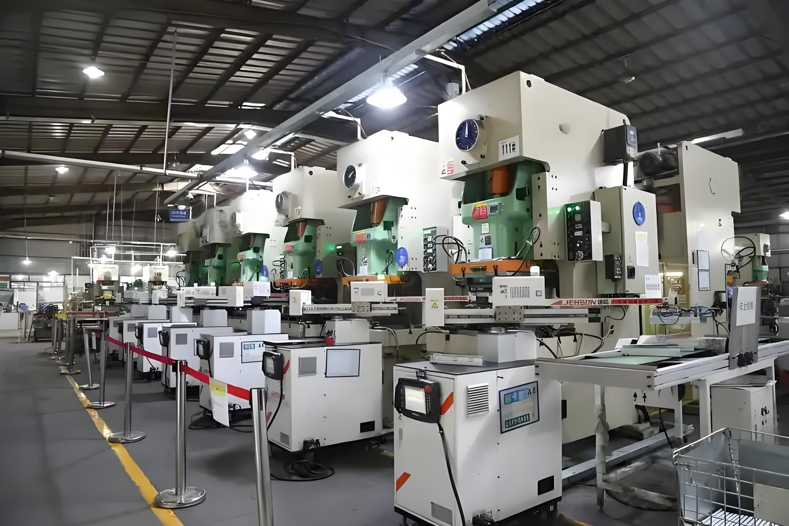
আপনি যখন একটি আধুনিক গাড়ি দেখেন, আপনি কি কখনো ভেবে দেখেছেন যে এত জটিল ধাতব উপাদান কিভাবে একত্রিত হয়? উত্তরটি হল কাস্টম অটোমোটিভ মেটাল স্ট্যাম্পিং ২০২৫ সালে গাড়ি উৎপাদনের মূল কেন্দ্রবিন্দুতে থাকবে এই প্রক্রিয়া। কিন্তু এটা আসলে কি এবং কেন এটা আজকের ক্রেতা, প্রকৌশলী এবং সোর্সিং টিমের জন্য এত গুরুত্বপূর্ণ?
কাস্টম অটোমোটিভ মেটাল স্ট্যাম্পিং এটি হল নির্দিষ্ট যানবাহন অ্যাপ্লিকেশনের জন্য সুনির্দিষ্ট, জটিল অংশগুলিতে সমতল ধাতব শীটগুলিকে আকৃতি দেওয়ার প্রক্রিয়া। বিশেষায়িত মুর এবং উচ্চ গতির প্রেস ব্যবহার করে, নির্মাতারা কাঁচা শীটকে ব্র্যাকেট এবং ক্লিপ থেকে শুরু করে দেহের শক্তিশালীকরণ, গভীর-টানা হাউজিং, ঢাল এবং বৈদ্যুতিক টার্মিনাল পর্যন্ত সবকিছুতে রূপান্তরিত করে। সাধারণ বা অফ-দ্য-শেল্ফ সমাধানের বিপরীতে, কাস্টম মেটাল স্ট্যাম্পিং এর মানে হল প্রতিটি অংশটি সঠিক স্পেসিফিকেশন অনুযায়ী ডিজাইন এবং উত্পাদিত হয় যা প্রতিটি স্বতন্ত্র অটোমোটিভ প্রয়োজনের জন্য ফিট, ফাংশন এবং গুণমান সরবরাহ করে।
যেখানে স্ট্যাম্পিং অটো ভ্যালু চেইনে ফিট করে
কল্পনা করুন যে আপনি কোন নতুন গাড়ির চারপাশে হাঁটছেন। আপনি সর্বত্র স্ট্যাম্পযুক্ত ধাতু লক্ষ্য করবেন: শরীরের নীচে, দরজা, ব্যাটারি ট্রে, সিট ফ্রেম, এমনকি ড্যাশবোর্ডের ভিতরে। অটোমোবাইল মেটাল স্ট্যাম্পিং নিম্নলিখিত বিষয়গুলির জন্য মৌলিকঃ
- কাঠামোগত ব্র্যাকেট এবং শরীরের শক্তিশালী
- ক্লিপ, ফিক্সিং টুলস এবং মাউন্ট প্লেট
- ব্যাটারি এবং ইভি ব্রেকিং
- বৈদ্যুতিক টার্মিনাল এবং বাসবার
- সেন্সর এবং মডিউলগুলির জন্য গভীর-টানা হাউজিং
এগুলি ধাতব স্ট্যাম্পিং অংশ এই প্রকল্পের লক্ষ্য হচ্ছে, ভবনটির কাঠামোগত অখণ্ডতা, বৈদ্যুতিক সংযোগ এবং গাড়ির নিরাপত্তা নিশ্চিত করা। প্রকৃতপক্ষে, বিদ্যুৎ এবং হালকা ওজন বাড়ার সাথে সাথে স্ট্যাম্পিং উন্নত উপকরণ (যেমন এইচএসএলএ স্টিল এবং অ্যালুমিনিয়াম) এবং জটিল ফর্মগুলি ব্যবহার করতে সক্ষম করে যা উভয় ক্রাশওয়ার্স্ট এবং দক্ষতা সমর্থন করে (শাওই) .
মেশিনিং বা কাস্টিংয়ের পরিবর্তে স্ট্যাম্পিং কখন বেছে নেবেন
জটিল মনে হচ্ছে? এখানে কেন অটোমোটিভ স্ট্যাম্পিং বেশিরভাগ অটোমোটিভ ধাতব উপাদানগুলির জন্য এটি পছন্দসই পছন্দঃ
- ইউনিট খরচ কম মাঝারি থেকে উচ্চ পরিমাণে
- দ্রুত চক্র সময় (পার্ট প্রতি সেকেন্ড)
- উচ্চ পুনরাবৃত্তিযোগ্যতা ঘন দূরত্বের জন্য
- স্কেলযোগ্যতা প্রোটোটাইপ থেকে বছরে লক্ষ লক্ষ
এটি মেশিনিংয়ের সাথে তুলনা করুন (ধীর, উচ্চতর ব্যয়, কম পরিমাণ বা পুরু অংশগুলির জন্য ভাল) বা castালাই (জটিল 3 ডি আকারের জন্য ভাল, তবে কম নির্ভুল এবং র্যাম্পে ধীর) । স্ট্যাম্পিং যখন আপনার পাতলা, শক্তিশালী এবং পুনরাবৃত্তিযোগ্য প্রয়োজন হয় তখন চমৎকার অটোমোবাইল মেটাল স্কেল অংশ।
| প্রক্রিয়া | জন্য সেরা | সাধারণ ভলিউম | চক্র সময় | সহনশীলতা |
|---|---|---|---|---|
| একক-হট ডাই | প্রোটোটাইপ, কম রান | 1–5,000 | ৫৩০ সেকেন্ড | ±0.20.5 মিমি |
| প্রগতিশীল মার্ফত | ব্র্যাকেট, টার্মিনাল, শেল্ড | 10,000–5,000,000+ | ০.৫ ২ সেকেন্ড | ±0.050.2 মিমি |
| স্থানান্তর/গভীরতা | হাউজিং, ট্রে, শেল | 5,000–500,000+ | ১৫ সেকেন্ড | ±0.10.3mm |
প্রধান বিষয়: ভলিউম বাড়ার সাথে সাথে স্ট্যাম্পিংয়ের একক খরচ নাটকীয়ভাবে হ্রাস পায়, এটি বেশিরভাগ অটোমোটিভ ধাতব অংশের জন্য সবচেয়ে ব্যয়বহুল এবং নির্ভরযোগ্য পথ তৈরি করে।
২০২৫ এবং তার পরেও কেন স্ট্যাম্পিং গুরুত্বপূর্ণ
২০২৫ সালে, হালকা, নিরাপদ এবং সস্তা গাড়ি সরবরাহের চাপ আগের চেয়ে বেশি। বৈদ্যুতিকীকরণ, নতুন দুর্ঘটনা মানদণ্ড এবং বৈশ্বিক প্রতিযোগিতার সাথে সাথে, গাড়ি নির্মাতারা তাদের সরবরাহ চেইনের থেকে আরো বেশি চাহিদা করছে। কাস্টম অটোমোটিভ মেটাল স্ট্যাম্পিং এই চ্যালেঞ্জগুলির মোকাবেলা করেঃ
- দ্রুত প্রোটোটাইপিং এবং নতুন ডিজাইনের জন্য সংক্ষিপ্ত সময়সীমা
- উন্নত উপকরণ (HSLA, অ্যালুমিনিয়াম) এর জন্য যথার্থ উত্পাদন
- কঠোর সহনশীলতা এবং বিশ্বমানের মানদণ্ডের সাথে সম্মতি
- প্রোটোটাইপ থেকে এসওপি (উত্পাদন শুরু) পর্যন্ত মসৃণ স্কেল আপ
সোর্সিং টিম এবং ইঞ্জিনিয়ারদের জন্য, এই গাইডটি সিদ্ধান্ত গ্রহণের কাঠামো সরবরাহ করেঃ কখন স্ট্যাম্পিং ব্যবহার করবেন, কী কী ক্ষমতা আশা করবেন এবং সরবরাহকারীদের কীভাবে তুলনা করবেন। উদাহরণস্বরূপ, আপনি যদি প্রগতিশীল-মরা কাস্টম অটোমোটিভ মেটাল স্ট্যাম্পিং অংশ, যেমন একটি সরবরাহকারী সঙ্গে কাজ Shaoyi ধাতু অংশ সরবরাহকারীএকটি নেতৃস্থানীয় সমন্বিত স্পষ্টতা স্বয়ংক্রিয় ধাতু অংশ সমাধান প্রদানকারী চীনআপনার প্রকল্পের DFM থেকে ভর উত্পাদন, তাদের শেষ থেকে শেষ ক্ষমতা এবং শক্তিশালী মানের সিস্টেম ধন্যবাদ streamline করতে পারেন।
আপনি যখন পড়বেন, আপনি প্রক্রিয়া, উপকরণ, সহনশীলতা এবং সম্মতি সম্পর্কে একটি সাধারণ শব্দভাণ্ডার অর্জন করবেন এবং আপনার পরবর্তী RFQ কে আরও স্মার্ট এবং আরও সফল করার জন্য ব্যবহারিক সরঞ্জামগুলি পাবেন। পরবর্তীঃ কিভাবে আপনার অংশের জ্যামিতি, বেধ এবং ভলিউম চাহিদার উপর ভিত্তি করে সঠিক স্ট্যাম্পিং প্রক্রিয়া নির্বাচন করবেন।
ভলিউম এবং জ্যামিতি দ্বারা সঠিক স্ট্যাম্পিং প্রক্রিয়া নির্বাচন
প্রগতিশীল ডাই বনাম ট্রান্সফার স্ট্যাম্পিং ট্রেড অফস
যখন আপনি একটি নতুন অংশ চালু করছেন, আপনি কিভাবে সেরাটি বেছে নেবেন? ধাতব স্ট্যাম্পিং প্রক্রিয়া বিশেষ করে যখন জ্যামিতি, বেধ, এবং ভলিউম সব টেবিলে আছে? কল্পনা করুন আপনি একটি কব্জিকে ভারসাম্যপূর্ণ বৈশিষ্ট্যযুক্ত একটি গভীর-টানা হাউজিংয়ের তুলনায় কয়েকটি বাঁক সহ ওজন করছেন। উত্তর প্রায়ই আপনার চাহিদা সঠিক সঙ্গে মিলে আসে স্ট্যাম্পিং এবং প্রেসিং পদ্ধতি।
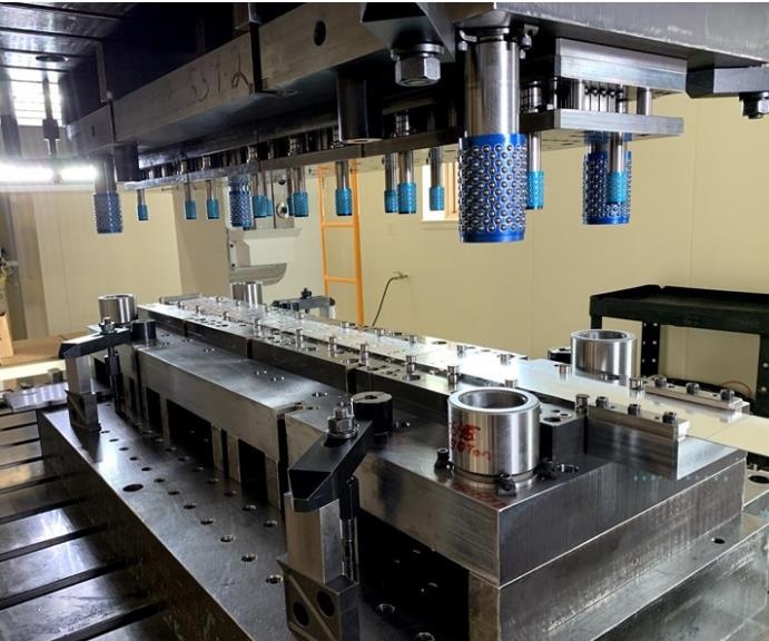
প্রগতিশীল ডাই স্ট্যাম্পিং একক মেইলে একাধিক স্টেশনে ধাতুর একটি অবিচ্ছিন্ন স্ট্রিপ ফিড করে। প্রতিটি স্টেশন অংশটি আরও কিছুটা গঠন করে বা কেটে দেয়, তাই শেষ স্টেশনে, আপনার একটি সমাপ্ত অংশ আছে। এই প্রক্রিয়াটি বিদ্যুতের মতো দ্রুত, এটিকে আদর্শ করে তোলে উচ্চ ভলিউম ধাতু স্ট্যাম্পিং ক্রেট, টার্মিনাল এবং শিল্ডের কথা ভাবুন যেখানে পুনরাবৃত্তিযোগ্যতা এবং অংশ প্রতি খরচ অত্যন্ত গুরুত্বপূর্ণ। প্রগতিশীল মরাও ফ্ল্যাঞ্জ, ল্যাভার্স এবং ছিদ্রযুক্ত গর্তের মতো বৈশিষ্ট্যগুলির জন্য দুর্দান্ত, তবে জ্যামিতি খুব গভীর বা জটিল নয়।
ট্রান্সফার ডাই স্ট্যাম্পিং ভিন্ন। এখানে, ফাঁকাটি প্রাথমিকভাবে পৃথক করা হয় এবং যান্ত্রিকভাবে স্টেশন থেকে স্টেশন থেকে স্থানান্তরিত হয়, প্রতিটি একটি নির্দিষ্ট অপারেশন সম্পাদন করে। এই পদ্ধতিটি বড় বা জটিল অংশগুলির জন্য বিশেষত গভীর আঁকা, একাধিক বাঁক বা জটিল আকারের অংশগুলির জন্য উজ্জ্বল। ট্রান্সফার ডাই নিম্ন থেকে মাঝারি ভলিউম বা অংশ যেখানে জ্যামিতি সহজভাবে একটি প্রগতিশীল ডাই সঙ্গে অর্জন করা যাবে না উপযুক্ত।
| প্রক্রিয়া | জন্য সেরা | উপাদানের পুরুত্ব | সাধারণ সহনশীলতা | চক্র সময় | ভলিউম উপযুক্ততা | মূল বৈশিষ্ট্যসমূহ |
|---|---|---|---|---|---|---|
| প্রগতিশীল মার্ফত | ব্র্যাকেট, টার্মিনাল, শেল্ড | 0.24.0 মিমি | ±0.050.2 মিমি | ০.৫ ২ সেকেন্ড | 10,000–5,000,000+ | দ্রুত, পুনরাবৃত্তিযোগ্য, উচ্চ উপাদান দক্ষতা |
| ট্রান্সফার ডাই | গভীর-টানা হাউজিং, কাঠামোগত অংশ | ০.৫ ৬.০ মিমি | ±0.10.3 মিমি | ১৫ সেকেন্ড | 5,000–500,000+ | জটিল আকার, গভীর প্রস্রাব, ঘন স্ট্যাক |
| ডিপ ড্র | কাপ, বাক্স, আবরণ | ০.৩ ২.৫ মিমি | ±0.10.3 মিমি | ২৬ সেকেন্ড | 1,000–250,000+ | গভীর গহ্বর, নিরবচ্ছিন্ন রূপ |
গভীর ড্র এবং যখন এটা একাধিক বাঁক অপস beats
এমন একটি অংশের কথা ভাবুন যার জন্য গভীর, মসৃণ গহ্বর প্রয়োজন, যেমন সেন্সর হাউজিং বা ব্যাটারি ট্রে। গভীর ড্রাগ স্ট্যাম্পিং ধাতুকে ধাপে ধাপে আকৃতিতে টানতে পারে, যা স্ট্যান্ডার্ড বাঁকগুলির চেয়ে আরও গভীরতার অনুমতি দেয়। যদি আপনার অংশের ব্যাসার্ধের চেয়ে গভীরতা বেশি প্রয়োজন হয়, গভীর ড্র প্রায়ই সবচেয়ে নির্ভরযোগ্য এবং খরচ কার্যকর শীট মেটাল প্রেসিং পছন্দ। এটিও সিলাইড এবং জয়েন্টগুলিকে কমিয়ে দেয়, শক্তি বৃদ্ধি করে এবং ফুটো হওয়ার ঝুঁকি হ্রাস করে।
এজ মানের জন্য ফাইনব্ল্যাঙ্কিং এবং ময়লা
কখনো কি অতি মসৃণ প্রান্ত বা সুনির্দিষ্ট সমতলতা সহ একটি অংশ প্রয়োজন? ফাইন ব্লাঙ্কিং এবং মুদ্রাঙ্কন বিশেষত্ব উত্পাদন প্রক্রিয়া বিকল্প। ফাইনব্ল্যাঙ্কিং প্রায় নিখুঁত প্রান্তের গুণমান এবং শক্ত সহনশীলতা সরবরাহ করে, যখন মুদ্রাঙ্কন নির্ভুল ফিট করার জন্য বৈশিষ্ট্যগুলি সমতল বা তীক্ষ্ণ করে। এগুলি প্রায়শই গিয়ার, বৈদ্যুতিক পরিচিতি এবং উচ্চ-কার্যকারিতা সংযোগকারীদের জন্য ব্যবহৃত হয় যেখানে গৌণ যন্ত্রপাতি পছন্দসই নয়।
প্রক্রিয়া নির্বাচনঃ একটি ব্যবহারিক চেকলিস্ট
- পর্যালোচনা অংশ মুদ্রণঃ জ্যামিতি, বেধ, সহনশীলতা, এবং বৈশিষ্ট্য বিবরণ
- অনুমানিত পরিমাণঃ স্বল্পমেয়াদী ধাতু স্ট্যাম্পিং (110,000) বনাম উচ্চ ভলিউম (100,000+)
- ম্যাচ প্রক্রিয়াঃ উচ্চ গতি এবং পুনরাবৃত্তি জন্য প্রগতিশীল, জটিলতা বা গভীরতা জন্য স্থানান্তর বা গভীর আঁকা
- বৈশিষ্ট্য কার্যকারিতা পরীক্ষা করুনঃ প্রান্ত কাছাকাছি ছিদ্র গর্ত, গভীর কাপ, ছাঁচনির্মাণ, flanges
- অটোমেশন প্রস্তুতি মূল্যায়ন করুনঃ ইন-ডি-ডিসটেনশনের পরিকল্পনা এবং ধাতু স্ট্যাম্পিং সরঞ্জাম সামঞ্জস্যতা
- পরীক্ষার পরিকল্পনা এবং বৈধতাঃ র্যাম্পের আগে প্রক্রিয়া স্থিতিশীলতা নিশ্চিত করুন
নিয়ম: যদি আপনার বার্ষিক পরিমাণ 100,000 এর বেশি হয় এবং অংশটির জ্যামিতি খুব জটিল না হয়, তবে প্রগতিশীল ডাই স্ট্যাম্পিং সাধারণত খরচ এবং গতির দিক থেকে ভালো হয়। গভীর ড্র বা অত্যন্ত জটিল আকৃতির জন্য, ট্রান্সফার ডাই বিনিয়োগের মূল্যবান।
হাইব্রিড এবং উন্নত প্রক্রিয়া সম্পর্কিত নোটসমূহ
কখনও কখনও সেরা পদ্ধতি হল হাইব্রিড: মূল আকৃতির জন্য প্রগতিশীল ডাই, অফলাইনে সেকেন্ডারি ট্যাপিং বা কয়েনিং এর সাথে। স্বয়ংক্রিয়করণ এবং ডাইয়ের মধ্যে সেন্সরগুলো শুধুমাত্র দুর্ঘটনা রোধ করে না, পাশাপাশি মান বাড়ায় এবং স্থিতিশীলতা কমায় - যা খুব গুরুত্বপূর্ণ উচ্চ ভলিউম ধাতু স্ট্যাম্পিং প্রকল্প।
- ডাই/প্রক্রিয়া পরিবর্তনের জন্য লাল পতাকা:
- অতিরিক্ত স্প্রিংব্যাক বা টলারেন্সের বাইরে বেঁকে যাওয়া
- ঘন ঘন ডায়েরী বা অত্যধিক স্ক্র্যাপিং
- অপ্রত্যাশিত পোশাক ধাতু স্ট্যাম্পিং সরঞ্জাম
- যেসব বৈশিষ্ট্য একযোগে নির্ভরযোগ্যভাবে গঠিত হতে পারে না
এই সমঝোতা এবং চেকপয়েন্টগুলি বোঝার মাধ্যমে, আপনি আপনার ইউটোমোটিভ স্ট্যাম্পিং প্রক্রিয়া সফলতার জন্য আপনি লাখো ক্রেট বা কয়েক হাজার গভীর-ড্রেন হাউজিং চালাচ্ছেন কিনা। পরবর্তীঃ কিভাবে উপাদান এবং লেপ নির্বাচন করা যায় যা প্রতিটি স্ট্যাম্প করা অংশের জন্য শক্তি, পরিবাহিতা এবং জারা প্রতিরোধের সরবরাহ করে।
অটোমোটিভ পরিবেশে বিজয়ী উপকরণ এবং লেপ
শক্তি ও গঠনযোগ্যতার জন্য ইস্পাতের গ্রেড
আপনি যখন কাস্টম অটোমোটিভ ধাতু স্ট্যাম্পিংয়ের জন্য উপকরণ নির্বাচন করছেন, তখন আপনি কিভাবে শক্তি, গঠনযোগ্যতা এবং খরচকে ভারসাম্যপূর্ণ করবেন, বিশেষ করে যখন নিরাপত্তা এবং স্থায়িত্বের বিষয়ে আলোচনা করা যায় না? উত্তরটি বোঝার সাথে শুরু হয় যে স্টিলের পরিসীমা উপলব্ধ স্টিল শীট স্ট্যাম্পিং এবং তাদের বিশেষ ভূমিকা অটোমোবাইল কাঠামো.
উচ্চ-শক্তি কম-লো-লিগ (এইচএসএলএ) এবং উন্নত উচ্চ-শক্তি স্টিল, যেমন দ্বৈত-ফেজ (ডিপি) এবং মার্টেন্সিটিক গ্রেড, আজকের স্ট্যাম্পড স্টিল শীট উপাদানগুলির মেরুদণ্ড। উদাহরণস্বরূপ, ডিপি 590 এবং ডিপি 980 স্টিলগুলি সাধারণত মেঝে প্যানেল, শক্তিশালীকরণ এবং দেহের পাশের জন্য ব্যবহৃত হয় কারণ তারা উচ্চ শক্তি এবং দুর্দান্ত গঠনযোগ্যতা সরবরাহ করে। মার্টেনসাইটিক স্টিলগুলি ক্রস সদস্য এবং অনুপ্রবেশ বিমগুলির জন্য বেছে নেওয়া হয়, যেখানে সংঘর্ষ প্রতিরোধের সমালোচনামূলক।
কিন্তু শক্তির সাথে কিছু কমিশনও আসে। উচ্চতর শক্তির স্টিলগুলি আরও চ্যালেঞ্জিং হতে পারে, কখনও কখনও বৃহত্তর সর্বনিম্ন বাঁক ব্যাসার্ধ এবং সাবধানে স্প্রিংব্যাক নিয়ন্ত্রণের প্রয়োজন হয়। সঠিক যান্ত্রিক বৈশিষ্ট্য পরিসীমা এবং লেপ সামঞ্জস্যের জন্য সর্বদা SAE J2329 বা ASTM A653/A924 দেখুন (SAE J2329) .
হালকা ওজন জন্য অ্যালুমিনিয়াম খাদ
কল্পনা করুন, আপনি গাড়ির ওজন কমাতে চান, যাতে আপনি আরও বেশি জ্বালানি খরচ করতে পারেন। সেখানেই অ্যালুমিনিয়াম ধাতু স্ট্যাম্পিং উজ্জ্বল। অ্যালুমিনিয়ামের মিশ্রণ যেমন 5052 এবং 5182 গঠনযোগ্যতা, জারা প্রতিরোধের এবং শক্তির একটি আকর্ষণীয় মিশ্রণ সরবরাহ করে। বাইরের প্যানেলগুলির জন্য, 6016 এবং 6022 তাদের ডান্ট প্রতিরোধের এবং পৃষ্ঠের মানের জন্য পছন্দসই। যদি আপনি কাঠামোগত অ্যাপ্লিকেশনগুলির পরে থাকেন, 5182 এবং 5754 কাজযোগ্যতা ত্যাগ না করেই উচ্চতর শক্তি সরবরাহ করে।
বৈদ্যুতিক অ্যাপ্লিকেশনগুলির জন্য, তামা এবং তামা খাদগুলি এখনও টার্মিনাল এবং বাসবারগুলির জন্য যেতে হয়, তবে অ্যালুমিনিয়াম ক্রমবর্ধমানভাবে ব্যবহার করা হয় যেখানে পরিবাহিতা এবং ওজন সাশ্রয় ভারসাম্য বজায় রাখতে হবে। যখন নির্দিষ্ট করা হয় অ্যালুমিনিয়াম শীট ধাতু স্ট্যাম্পিং , সবসময় উপযুক্ত tempers এবং postforming তাপ চিকিত্সা প্রয়োজনীয়তা জন্য চেক করুন।
লেপ এবং ক্ষয় কৌশল
ক্ষয় এমনকি সবচেয়ে শক্তিশালী স্ট্যাম্প অংশকেও হ্রাস করতে পারে। এজন্যই ইস্পাত এবং অ্যালুমিনিয়াম স্ট্যাম্পিংয়ের জন্য গ্যালভানিয়াল, হট-ডিপ গ্যালভানাইজড এবং ই-কোটের মতো লেপগুলি অত্যন্ত গুরুত্বপূর্ণ। জন্য গ্যালভানাইজড স্টিল স্ট্যাম্পিং , এএসটিএম A653 এবং A924 জিংক এবং জিংক-আয়রন লেপগুলির জন্য রূপরেখা প্রয়োজনীয়তা, যা শরীরের নীচে এবং উন্মুক্ত প্যানেলগুলির জন্য মানক। ই-কোট এবং পাউডার কোট বিশেষ করে রাস্তা লবণের সংস্পর্শে থাকা উপাদানগুলির জন্য সুরক্ষার আরেকটি স্তর যুক্ত করতে পারে।
স্টেইনলেস স্টিলের স্ট্যাম্পিং প্রায়শই নিষ্কাশন, তাপ শেল্ড এবং ট্রিমিংয়ের জন্য বেছে নেওয়া হয়, 304 এবং 409 এর মতো গ্রেডের জন্য ধন্যবাদ যা দুর্দান্ত জারা এবং তাপমাত্রা প্রতিরোধের প্রস্তাব দেয়। সোল্ডারযোগ্যতার জন্য, মনে রাখবেন যে কিছু লেপ এবং স্টেইনলেস অ্যালোগুলির জন্য বিশেষ ফিলার উপকরণ বা আঠালো লিপিং কৌশল প্রয়োজন হতে পারে।
| বস্তুগত পরিবার | সাধারণ বেধ (মিমি) | সৃষ্টি করা কঠিন | সাধারণ ত্রুটি | প্রস্তাবিত লেপ/ফিনিস |
|---|---|---|---|---|
| এইচএসএলএ স্টিল | 0.7–2.5 | মাঝারি | স্প্রিংব্যাক, প্রান্ত ফাটল | গ্যালভানিয়াল, ই-কোট |
| ডিপি/মার্টেনসিটিক স্টিল | 0.8–2.0 | চ্যালেঞ্জিং | স্প্রিংব্যাক, ঝাঁকুনি | গ্যালভানাইজড, পেইন্ট |
| এলুমিনিয়াম লৈগ | 0.7–2.0 | সহজমাঝারি | পৃষ্ঠের স্ক্র্যাচ, জ্বালা | অ্যানোডাইজ, ই-কোট |
| স্টেইনলেস স্টিল | 0.6–1.5 | মাঝারি | কাজ শক্ত, সরঞ্জাম পরিধান | পোলিশ, প্যাসিভেট |
| ক্যাম্পার অ্যালোই | 0.2–1.0 | সহজ | বার্স, বিকৃতি | টিনের প্লেট, কোনটিই নেই |
ধাতু মিশ্রণ? কি করা উচিত এবং কি করা উচিত নয়
- ইস্পাতের সাথে আলুমিনিয়াম যোগ করার সময় গ্যালভানিক ক্ষয় রোধে ইসোলেটর বা কোটিং ব্যবহার করুন।
- যদি পার্টগুলি ওয়েল্ড বা বন্ড করা হয় তবে সামঞ্জস্যপূর্ণ কোটিং নির্দিষ্ট করুন।
- স্টেইনলেস এবং কার্বন স্টিল পাসিভেটেড বা কোটযুক্ত না হওয়া পর্যন্ত সরাসরি যোগাযোগে মিশ্রিত করবেন না।
- বার নিয়ন্ত্রণ উপেক্ষা করবেন না—বিশেষত স্টেইনলেস স্টিলের স্ট্যাম্পিং এবং বৈদ্যুতিক যোগাযোগের ক্ষেত্রে।
ব্যবহারিক পরামর্শ: যদি আপনি স্টেইনলেস বা উচ্চ-শক্তি ইস্পাতের মতো অ্যাব্রেসিভ সংকর ধাতুর স্ট্যাম্পিং করেন তবে উচ্চ পরিধান প্রতিরোধের সাথে টুল ইস্পাত নির্দিষ্ট করুন এবং টুল জীবন প্রক্ষেপণের জন্য অনুরোধ করুন। এটি দীর্ঘ উত্পাদন চক্রে খরচ কম রাখে।
সঠিক উপকরণ এবং ফিনিশ নির্বাচন করা কেবল পারফরম্যান্সের বিষয়টি নয়—এটি দীর্ঘমেয়াদী নির্ভরযোগ্যতা এবং মোট মালিকানা খরচের বিষয়টি। সর্বদা SAE এবং ASTM মানগুলির সাথে সামঞ্জস্য নিশ্চিত করতে আপনার RFQ-তে মিল সার্টিফিকেশন এবং কোটিং পুরুতা প্রতিবেদনের অনুরোধ করুন। পরবর্তীতে, আমরা ডিএফএম নিয়মগুলি ভেঙে ফেলব যা আপনাকে খুচরা অংশ প্রতিরোধ করতে এবং শুরু থেকেই পুনরাবৃত্তিযোগ্য, উচ্চমানের অংশ তৈরি করতে সাহায্য করবে।
খুচরা অংশ প্রতিরোধ এবং পুনরাবৃত্তিযোগ্যতা নিশ্চিতকরণের জন্য ডিএফএম নিয়ম
বেঁক ব্যাসার্ধ, প্রান্ত দূরত্ব এবং ছিদ্র স্থাপন: স্ট্যাম্পিং শীট মেটাল সাফল্যের মূল কথা
আপনি কি কখনও ভেবেছেন, কেন কিছু স্ট্যাম্পিং শীট মেটাল প্রকল্প ঘড়ির মতো চলে, আবার কিছু প্রকল্পে বর্জ্য এবং সরঞ্জাম সংঘর্ষের পরিমাণ বেড়ে যায়? সাফল্যের উত্তরটি প্রায়শই কয়েকটি ডিজাইন-ফর-ম্যানুফ্যাকচারেবিলিটি (ডিএফএম) নিয়মের মধ্যে নিহিত থাকে। বেঁক, ছিদ্র এবং প্রান্তগুলির মতো বৈশিষ্ট্যগুলির জন্য প্রমাণিত নির্দেশিকা অনুসরণ করে, আপনি ত্রুটি এবং চেষ্টা-ভুলের পরিমাণ উল্লেখযোগ্যভাবে কমিয়ে আনতে পারেন এবং পিপিএপি (PPAP) অনুমোদনের জন্য আপনার পথটি দ্রুত করে তুলতে পারেন।
| বৈশিষ্ট্য ধরন | ডিজাইন-ফর-ম্যানুফ্যাকচারেবিলিটি (ডিএফএম) নিয়ম/সূত্র | সাধারণ সহনশীলতা | সাধারণ ব্যর্থতার মাধ্যম |
|---|---|---|---|
| বেঞ্চ রেডিয়াস | ন্যূনতম অভ্যন্তরীণ ব্যাসার্ধ = 1x উপকরণের পুরুতা (ইস্পাতের ক্ষেত্রে), অ্যালুমিনিয়ামের ক্ষেত্রে 1.5x | ±0.2–0.5 মিমি | ফাটন, স্প্রিংব্যাক, কুঁচকে যাওয়া |
| ছিদ্র থেকে প্রান্ত দূরত্ব | >= 2x উপকরণের পুরুতা | ±0.10–0.25 mm | প্রান্ত ফাটা, বিকৃতি |
| ছিদ্র থেকে ছিদ্র দূরত্ব | >= 2x উপকরণের পুরুতা | ±0.10–0.25 mm | বিকৃতি, পাঞ্চ ভাঙন |
| ফ্ল্যাঙ্গ প্রস্থ | ন্যূনতম প্রস্থ = 4x পুরুতা | ±0.3–0.5 মিমি | কুঁচকানো, অসম্পূর্ণ গঠন |
| খচিত উচ্চতা | সর্বোচ্চ উচ্চতা = 3x পুরুতা | ±0.3–0.5 মিমি | ভাঙন, কুঁচকে যাওয়া |
| ছিদ্র ক্লিয়ারেন্স | 5–10% > উপাদানের পুরুতা (প্রতি পার্শ্ব) | ±0.05–0.1 mm | বার্স, পঞ্চ ক্ষয় |
প্রতিটি ধাতু স্ট্যাম্পিং অংশের জন্য, এই সংখ্যাগুলি একটি শুরুর বিন্দু। অ-গুরুত্বপূর্ণ বৈশিষ্ট্যগুলিতে সহনশীলতা শক্ত করা কেবল খরচ এবং ঝুঁকি বাড়িয়ে দেয়। আপনার সর্বাধিক সংকীর্ণ ব্যান্ডগুলি কার্যকরী ডেটাম এবং সমাবেশ-গুরুত্বপূর্ণ গর্তগুলিতে ফোকাস করুন, কম গুরুত্বপূর্ণ অঞ্চলগুলিকে প্রশস্ততর ব্যান্ডের মধ্যে ভাসমান রেখে দিন।
ক্যারিয়ার ডিজাইন, স্ট্রিপ লেআউট এবং ডাই পছন্দসমূহ
কল্পনা করুন যে আপনি একটি নতুন ব্র্যাকেটের জন্য প্রগতিশীল ডাই পরিকল্পনা করছেন। ক্যারিয়ার—পদার্থের স্ট্রিপ যা আপনার অংশগুলিকে প্রতিটি ষ্টেশনের মধ্য দিয়ে চলাচলের সময় ধরে রাখে—সমতলতা থেকে শুরু করে স্ক্র্যাপ হার পর্যন্ত সবকিছু আকার দেয়। এখানে যা গুরুত্বপূর্ণ:
- টিপিং বা বিকৃতি রোধ করতে ক্যারিয়ার যথেষ্ট প্রশস্ত রাখুন (অংশের প্রস্থের কমপক্ষে 1.5x)।
- একপাশে অত্যধিক বল প্রয়োগ এড়াতে ষ্টেশনের কাজগুলি সমানভাবে ভারসাম্য রাখুন—এটি আপনার স্টিল স্ট্যাম্পিং ডাইগুলিকে সঠিকভাবে চালিত রাখে।
- সংগঠন বজায় রাখতে এবং ভবিষ্যতে সম্পাদনার জন্য সুযোগ করে দেওয়ার জন্য পাইলট গর্ত এবং অনুপস্থিত ষ্টেশনগুলি ব্যবহার করুন।
- অপটিমাল ম্যাটেরিয়াল ইয়ার্ডের জন্য স্ট্রিপ লেআউট পরিকল্পনা করুন - অংশগুলি ঘন ঘন নেস্টিং করে অপচয় কমায় এবং প্রতি মেটাল স্ট্যাম্পিং অংশের খরচ কমায়।
আপনার টুলমেকারের সাথে প্রাথমিক সহযোগিতা লাভজনক। ইস্পাত কাটার আগে স্ট্রিপ লেআউটগুলি পুনরাবৃত্তি করে, আপনি প্রতি অংশে (স্টেশনগুলিতে) আঘাত কমাতে পারেন, প্রয়োজনীয় টনেজ কমাতে পারেন এবং আউটপুট উন্নত করতে পারেন। এটি উচ্চ-ভলিউম নির্ভুল মেটাল স্ট্যাম্পিং অংশগুলির জন্য গুরুত্বপূর্ণ, যেখানে লেআউটের কয়েক মিলিমিটার বার্ষিক সঞ্চয়ে হাজার হাজার টাকা হতে পারে।
ডাই সুরক্ষা, ডাই-এ ট্যাপিং এবং বর্জ্য প্রতিরোধ
এটি খুব বেশি মনে হচ্ছে? তা হওয়ার দরকার নেই। আধুনিক কাস্টম মেটাল স্ট্যাম্পিং ডাইগুলি স্তরযুক্ত সুরক্ষা দিয়ে তৈরি:
- কীড ইনসার্টগুলি: ভুল সমবায় প্রতিরোধ করুন এবং রক্ষণাবেক্ষণ সহজ করুন।
- ওয়্যার স্ট্রিপগুলি: ডাই জীবন বাড়ান, বিশেষ করে ক্ষয়কারী উপকরণগুলি সহ।
- ইন-ডাই সেন্সর: ডাই-এর ক্ষতি হওয়ার আগে মিসফিড বা ডবল হিট সনাক্ত করুন।
- ডাই-এ ট্যাপিং: খরচ বাদ দিয়ে লাইনে থ্রেড যোগ করে।
গভীর বৈশিষ্ট্য বা উচ্চ-গঠন লোডের জন্য, ফর্ম রিলিফ, ড্র বিড এবং সঠিক ব্লাঙ্কহোল্ডার বল না ভুলবেন না—এগুলি সামগ্রী মসৃণভাবে প্রবাহিত রাখে এবং ছিঁড়ে যাওয়া বা কুঁচকানো প্রতিরোধ করে।
ব্যবহারিক অন্তদৃষ্টি: ডাই-এ ওভারবেন্ডিং বৈশিষ্ট্য দিয়ে স্প্রিংব্যাকের জন্য ক্ষতিপূরণ করুন এবং পুনরাবৃত্তিমূলক পরীক্ষা করার পরিকল্পনা করুন। কেবল 1–2° কোণগুলি সামঞ্জস্য করে একটি অস্থির স্ট্যাম্পিং শীট মেটাল অংশকে খরচ বাদে পুনরায় কাজ করা ছাড়াই স্পেকে আনতে পারে।
ডিএফএম থেকে নির্ভরযোগ্য উৎপাদন: প্রারম্ভিক অংশগ্রহণের গুরুত্ব কেন তা হল?
টুলমেকারদের প্রারম্ভিকভাবে জড়িয়ে দেওয়া কেবল একটি সেরা অনুশীলন নয়—এটি শক্তিশালী, পুনরাবৃত্তিমূলক অংশের দিকে একটি সংক্ষিপ্তপথ। ইস্পাত কাটার আগে ডিএফএম পরিবর্তনগুলি লক করে আপনি খরচের পুনরায় পরিবর্তন এবং সময় হারানো এড়াতে পারেন। কাস্টম মেটাল স্ট্যাম্পিং ডাই প্রকল্পগুলির জন্য এই পদ্ধতি বিশেষভাবে গুরুত্বপূর্ণ, যেখানে জটিলতা এবং পরিমাণ প্রতিটি ডিজাইন সিদ্ধান্তকে বাড়িয়ে দেয়।
যেহেতু আপনি এগিয়ে যাচ্ছেন, মনে রাখবেন: স্মার্ট DFM সর্বত্র নিখুঁততা অনুসরণ করা নয়—এটি সংস্থানগুলি সেখানে কেন্দ্রীভূত করা যেখানে এগুলো সবচেয়ে বেশি গুরুত্বপূর্ণ। পরবর্তীতে, আমরা দেখব কীভাবে মান পদ্ধতি এবং PPAP ফ্রেমওয়ার্ক আপনার স্ট্যাম্পড অংশগুলি প্রতিবার সর্বোচ্চ মানের সম্মতি রক্ষা করে।
IATF এবং PPAP-এর সঙ্গে সামঞ্জস্যপূর্ণ মান পদ্ধতি
APQP গেটস এবং ডেলিভারেবলস: মানের জন্য প্রস্তুতি
আপনি যখন অটোমোটিভ কম্পোনেন্টের জন্য মেটাল স্ট্যাম্পিংয়ের উপর , কীভাবে আপনি নিশ্চিত হবেন যে প্রতিটি অংশ আপনার প্রয়োজনীয়তা পূরণ করবে—আজ এবং প্রতিটি ভবিষ্যতের রানে? উত্তরটি হল IATF 16949 এর মতো শক্তিশালী মান ফ্রেমওয়ার্ক এবং APQP/PPAP প্রক্রিয়ায়। জটিল শোনাচ্ছে? চলুন এটিকে পদক্ষেপে পদক্ষেপে ভেঙে ফেলি যাতে আপনি আত্মবিশ্বাসের সাথে সরবরাহকারী মান পরিচালনা করতে পারেন, প্রকল্প শুরু থেকে উৎপাদন অনুমোদন পর্যন্ত।
অ্যাডভান্সড প্রোডাক্ট কোয়ালিটি প্ল্যানিং (APQP) হল একটি পর্যায়ক্রমিক পদ্ধতি যা গাড়ির ধাতব স্ট্যাম্পিংয়ের উন্নয়নের কাঠামো দেয়। এটি আপনার সরবরাহকারীর ক্রিয়াকলাপগুলিকে আপনার প্রত্যাশার সঙ্গে সামঞ্জস্য করে, ঝুঁকি কমায় এবং চালু হওয়ার জন্য প্রস্তুতি নিশ্চিত করে। APQP-এর পাঁচটি পর্যায় হল:
| APQP পর্যায় | কি স্ট্যাম্পিং কার্যক্রম | সাধারণ নিদর্শন |
|---|---|---|
| 1. পরিকল্পনা | সম্ভাব্যতা পর্যালোচনা, DFM অধ্যয়ন | DFMEA, প্রাথমিক প্রক্রিয়া প্রবাহ |
| 2. পণ্য ডিজাইন ও উন্নয়ন | উপকরণ নির্বাচন, অঙ্কন প্রকাশ | ফুলকি অঙ্কন, উপকরণ সার্টিফিকেট |
| 3. প্রক্রিয়া ডিজাইন ও উন্নয়ন | ডাই ডিজাইন, PFMEA, নিয়ন্ত্রণ পরিকল্পনা | PFMEA, নিয়ন্ত্রণ পরিকল্পনা, লেআউট |
| 4. পণ্য ও প্রক্রিয়া যাথার্থ্যকরণ | পরীক্ষামূলক চালান, ক্ষমতা পরীক্ষা, PPAP জমা | মাত্রিক প্রতিবেদন, ক্ষমতা অধ্যয়ন |
| 5. প্রতিক্রিয়া, মূল্যায়ন ও উন্নতি | হার অনুযায়ী চালান, শেখা পাঠ | SPC চার্ট, নিরীক্ষা প্রতিবেদন |
প্রতিটি পর্যায় পূর্ববর্তী পর্যায়ের উপর ভিত্তি করে গঠিত হয়, যাতে উৎপাদনে পৌঁছানোর আগে প্রতিটি ঝুঁকি শনাক্ত ও সমাধান করা হয়েছে। এই প্রক্রিয়াটি কেবলমাত্র কাগজপত্র তৈরির একটি অনুশীলন নয় - এটি অপ্রত্যাশিত বিষয়, বিলম্ব এবং ব্যয়বহুল পুনঃকাজ এড়ানোর জন্য একটি প্রমাণিত পদ্ধতি।
স্ট্যাম্পড পার্টসের জন্য PPAP উপাদান: কী আশা করা যায়
একবার APQP ভিত্তি স্থাপন করার পরে, প্রোডাকশন পার্ট অ্যাপ্রুভাল প্রসেস (পিপিএপি) আপনার লঞ্চের জন্য আপনার গেটকিপার হয়ে ওঠে। জন্য ধাতব ট্যাম্পিং সেবা , পিপিএপি হল শিল্পের মান যা প্রমাণ করে যে আপনার সরবরাহকারী সমস্ত স্পেসিফিকেশন মেনে অংশগুলি নিয়মিতভাবে সরবরাহ করতে পারবেন। কিন্তু স্ট্যাম্পিং পিপিএপি-এর মধ্যে কী রয়েছে?
- গোলাকার অঙ্কন (সমস্ত গুরুত্বপূর্ণ মাত্রা এবং নোটসহ)
- প্রকৌশল পরিবর্তন নথি (প্রযোজ্য হলে)
- ডিএফএমইএ এবং পিএফএমইএ (ডিজাইন এবং প্রক্রিয়ার জন্য ঝুঁকি বিশ্লেষণ)
- প্রক্রিয়া ফ্লো ডায়াগ্রাম (প্রতিটি পদক্ষেপের দৃশ্যমান মানচিত্র)
- নিয়ন্ত্রণ পরিকল্পনা (প্রতিটি ঝুঁকি কীভাবে পর্যবেক্ষণ এবং নিয়ন্ত্রণ করা হয়)
- গেজ R&R এবং MSA (গুরুত্বপূর্ণ বৈশিষ্ট্যের জন্য পরিমাপন সিস্টেম বিশ্লেষণ)
- মাত্রিক ফলাফল (আসল পরিমাপনগুলি vs. প্রিন্টের সাথে)
- উপকরণ এবং কোটিং সার্টিফিকেশন (SAE/ASTM স্পেসিফিকেশনের সাথে মেলে)
- ক্ষমতা অধ্যয়ন (ছিদ্র অবস্থান, বেঁকে যাওয়ার কোণ, সমতলতা, বার উচ্চতা এর মতো CTQ বৈশিষ্ট্যের জন্য Cp/Cpk)
- চেহারা অনুমোদন (যদি সৌন্দর্য গুরুত্বপূর্ণ হয়)
- SPC চার্ট (চলমান প্রক্রিয়া নিয়ন্ত্রণের জন্য)
- নমুনা অংশ (প্রাথমিক উৎপাদন চক্র থেকে)
পাঁচটি পিপিএপি স্তর রয়েছে, লেভেল 1 (শুধুমাত্র ওয়ারেন্টি) থেকে শুরু করে লেভেল 5 (সম্পূর্ণ নথিপত্র এবং সাইটে পর্যালোচনা সহ)। বেশিরভাগ ক্ষেত্রেই অটোমোটিভ স্ট্যাম্পিং কোম্পানি , লেভেল 3 মান হিসাবে প্রযোজ্য—নমুনা সহ সম্পূর্ণ জমা দেওয়া—যতক্ষণ না গ্রাহকের প্রয়োজনীয়তা অন্যথা নির্দিষ্ট করে। প্রত্যাশা পরিষ্কার করে নিন আবেদন পত্রের (RFQ) পর্যায়ে, পরবর্তীতে অপ্রত্যাশিত কোন ঘটনা এড়াতে।
প্রো টিপ: প্রাথমিক প্রক্রিয়া প্রবাহ চিত্র এবং ঝুঁকি পর্যালোচনা হল আপনার রান-অ্যাট-রেট ব্যর্থতা প্রতিরোধের সেরা বীমা। প্রক্রিয়াটি ম্যাপ করা শেষ মুহূর্তের জন্য অপেক্ষা করবেন না—সমস্যাগুলি ধরে ফেলুন যতক্ষণ না সেগুলি পথরোধকারী হয়ে ওঠে।
ডিএফএমইএ, পিএফএমইএ এবং নিয়ন্ত্রণ পরিকল্পনার সংযোগ: ক্রিয়াশীল মূল সরঞ্জামসমূহ
ধরুন আপনি একটি নতুন ব্র্যাকেট চালু করছেন। অঙ্কন থেকে নির্ভরযোগ্য বৃহৎ উৎপাদনের যাত্রা তিনটি মূল সরঞ্জামের উপর নির্ভরশীল:
- ডিএফএমইএ (ডিজাইন ব্যর্থতা মোড এবং প্রভাব বিশ্লেষণ): অংশটির ডিজাইনে যা কিছু ভুল হতে পারে তা ভবিষ্যদ্বাণী করে—যেমন প্রান্তের খুব কাছাকাছি একটি ছিদ্র ফাটল তৈরি করতে পারে।
- PFMEA (প্রক্রিয়া FMEA): এটি সম্ভাব্য প্রক্রিয়া ব্যর্থতা চিহ্নিত করে - ধরুন, ডিম্বাকৃতির ছিদ্র বা অতিরিক্ত বার্ন তৈরি করে এমন একটি পাঞ্চ ক্ষয়। এটি একটি গতিশীল নথি যা প্রক্রিয়ার সাথে সাথে আপডেট হয় (F7i ব্লগ) .
- নিয়ন্ত্রণ পরিকল্পনা: প্রতিটি ঝুঁকি কীভাবে নিয়ন্ত্রিত হবে তার তালিকা করে - যেমন মিসফিডের জন্য ডাই-এ সেন্সর বা বেঁকে যাওয়া কোণের জন্য SPC পরীক্ষা।
এই নথিগুলি ঘনিষ্ঠভাবে সংযুক্ত: DFMEA PFMEA-কে অবহিত রাখে, যা আবার নিয়ন্ত্রণ পরিকল্পনার আকার দেয়। যখন আপনি প্রিসিজন মেটাল স্ট্যাম্পিং পরিষেবা দিয়ে কাজ করছেন, তখন স্পষ্ট প্রমাণের জন্য জিজ্ঞাসা করুন যে এই মূল সরঞ্জামগুলি শুধুমাত্র সম্পন্ন হয়নি, বরং সক্রিয়ভাবে উন্নতি করতে এবং ত্রুটি প্রতিরোধে ব্যবহৃত হচ্ছে
চেকলিস্ট: স্ট্যাম্পিং PPAP-তে কী থাকা উচিত?
- বেলুন আকৃতির চিত্র যেখানে CTQ বৈশিষ্ট্যগুলি হাইলাইট করা হয়েছে
- DFMEA, PFMEA এবং নিয়ন্ত্রণ পরিকল্পনা (স্বাক্ষরিত এবং তারিখ প্রদত্ত)
- প্রক্রিয়া ফ্লো ডায়াগ্রাম
- সামগ্রী এবং কোটিং সার্টিফিকেট (SAE/ASTM সম্মতিপূর্ণ)
- মাত্রা এবং ক্ষমতা প্রতিবেদন (গুরুত্বপূর্ণ বৈশিষ্ট্যের জন্য Cp/Cpk)
- গেজ R&R এবং ক্যালিব্রেশন রেকর্ড
- চলমান পর্যবেক্ষণের জন্য SPC চার্ট
- উপস্থিতি অনুমোদন (যদি প্রয়োজন হয়)
- নমুনা অংশ এবং ধরে রাখার রেকর্ড
এই চেকলিস্টটি অনুসরণ করে এবং সাম্প্রতিকতম PPAP ম্যানুয়াল এবং IATF ধারা উল্লেখ করে, আপনি আপনার অটোমোটিভ ধাতব স্ট্যাম্পিং শিল্প এবং গ্রাহক-নির্দিষ্ট প্রয়োজনীয়তা উভয়ই পূরণ করবেন। ভুলবেন না: সঠিক PPAP স্তরটি প্রোগ্রামের ঝুঁকি, জটিলতা এবং সময়ের উপর নির্ভর করে - আপনার সরবরাহ প্রক্রিয়ার শুরুতেই এটি আলোচনা করুন।
দৃঢ় মানের সিস্টেম থাকার সাথে, আপনি ক্ষমতা প্রমাণ করতে প্রস্তুত এবং চলমান উন্নতি নিশ্চিত করতে পারবেন। পরবর্তীতে, আমরা পরিদর্শন এবং SPC পদ্ধতি সম্পর্কে আলোচনা করব যা আপনার স্ট্যাম্পড অংশগুলিকে নির্দিষ্ট স্পেসিফিকেশনের মধ্যে রাখবে, প্রতিটি শিফটের পর শিফটে।
পরিদর্শন এবং SPC পদ্ধতি যা ক্ষমতা প্রমাণ করে
সাধারণ বৈশিষ্ট্যের জন্য মেট্রোলজি পদ্ধতি
যখন আপনি একটি আধুনিক অটোমোটিভ প্রোগ্রামে হাজার হাজার মেটাল স্ট্যাম্পিং কম্পোনেন্ট পরিচালনা করছেন, তখন আপনি কীভাবে নিশ্চিত করবেন যে প্রতিটি স্ট্যাম্পড অংশই স্পেসিফিকেশন মেনে চলছে— পুনঃকাজ বা ঝুঁকির মধ্যে ডুবে না গিয়ে? উত্তরটি হল বুদ্ধিমান পরিমাপ, লক্ষ্যযুক্ত নমুনা সংগ্রহ এবং প্রক্রিয়া নিয়ন্ত্রণের সাথে সতেজে সময়ে সময়ে পরিমাপের সংমিশ্রণ। চলুন দেখে নেওয়া যাক কী কী পদ্ধতি সাধারণত সবচেয়ে ভালো কাজ করে মুদ্রিত ধাতব অংশ এবং সেই সব সরঞ্জাম যা কাজটি সম্পন্ন করে।
| সিটিকিউ বৈশিষ্ট্য | পরিমাপ যন্ত্র | সাধারণ সহনশীলতা | সুপারিশকৃত সিপিকে |
|---|---|---|---|
| গর্তের ব্যাস/অবস্থান | সিএমএম, 3ডি লেজার স্ক্যানার, গেজ পিন | ±0.050.15 মিমি | ≥ ১.৩৩ |
| বেঁকে যাওয়ার কোণ | ডিজিটাল প্রোট্র্যাক্টর, লেজার স্ক্যানার | ±1° | ≥ ১.৩৩ |
| সমতলতা | পৃষ্ঠতল প্লেট, উচ্চতা গেজ | ≤ 0.2 মিমি | ≥ ১.৩৩ |
| বুর উচ্চতা | প্রোফাইলোমিটার, মাইক্রোমিটার | ≤ 0.05 মিমি | ≥ ১.৩৩ |
| ট্রিম লাইন | 3D স্ক্যানার, ভিজুয়াল গেজ | ±0.2 মিমি | ≥ ১.৩৩ |
স্থানাঙ্ক পরিমাপক মেশিন (সি এম এম) হল নির্ভুলতার ক্ষেত্রে স্বর্ণ প্রমাণ ধাতব স্ট্যাম্পড অংশ কিন্তু জটিল বা পৌঁছানোর কঠিন বৈশিষ্ট্যগুলির জন্য, 3D লেজার স্ক্যানিং সিস্টেমগুলি দ্রুত, পূর্ণ-ক্ষেত্রের ডেটা সরবরাহ করে। এই সরঞ্জামগুলি বিশেষভাবে মুদ্রাকর্ষণ বিশ্লেষণ, জিডিঅ্যান্ডটি পরীক্ষা এবং উচ্চ পরিমাণ স্ট্যাম্পিং পরিবেশ (3D স্ক্যানটেক) .
একটি স্মার্ট ইনস্পেকশন পরিকল্পনা তৈরি করা
অনেক ডেটা মতো শোনাচ্ছে? হ্যাঁ হতে পারে - কিন্তু রিস্ক-ভিত্তিক স্যাম্পলিং পরিকল্পনার মাধ্যমে, আপনি প্রকৃত গুরুত্বপূর্ণ বিষয়গুলির উপর ফোকাস করবেন। এটি কীভাবে অটোমোটিভ প্ল্যান্টগুলি দৃষ্টিভঙ্গি গ্রহণ করে ম্যানুফ্যাকচারিং স্ট্যাম্পিং পরীক্ষা:
- প্রথম আর্টিকেল ইনস্পেকশন (FAI): প্রতি টুল ক্যাভিটির 5–10 প্রাথমিক অংশের উপর 100% CTQ বৈশিষ্ট্য
- নিয়মিত উৎপাদন: ঝুঁকি এবং ত্রুটির ইতিহাসের উপর ভিত্তি করে প্রতি শিফট বা প্রতি লটে 1–5 অংশ স্যাম্পল করুন
- উচ্চ ঝুঁকি/লঞ্চ: নতুন বা অস্থিতিশীল প্রক্রিয়ার জন্য ফ্রিকোয়েন্সি বাড়ানো হয় বা 100% পরিদর্শনে স্থানান্তর করা হয়
গ্রহণযোগ্যতা মানদণ্ড Cpk মানের সাথে সংযুক্ত করা উচিত: বেশিরভাগ স্ট্যাম্পড অংশের জন্য 1.33 বা তার বেশি Cpk হল ন্যূনতম, কিন্তু কিছু গ্রাহক বা CTQ-এর জন্য 1.67 প্রয়োজন হতে পারে। যদি কোনও বৈশিষ্ট্য 1.33-এর নিচে চলে যায়, তাহলে মূল কারণ তদন্ত এবং সংশোধনমূলক পদক্ষেপ শুরু করুন - প্রায়শই পাঞ্চ ক্ষয়, ভুল খাওয়ানো বা নিয়ন্ত্রণহীন উপকরণ দায়ী হয়।
এসপিসি যা প্রকৃত সংশোধনমূলক পদক্ষেপ গ্রহণে সাহায্য করে
পরিসংখ্যানগত প্রক্রিয়া নিয়ন্ত্রণ (এসপিসি) কেবল চার্টগুলি প্লট করা নয় - এটি ত্রুটিগুলি হয়ে ওঠার আগে প্রবণতা ধরা দেয়। স্ট্যাম্পড মেকানিক্যাল পার্ট অ্যাসেম্বলি এবং ছিদ্রের অবস্থান বা বেঁকে যাওয়া কোণ সহ গুরুত্বপূর্ণ বৈশিষ্ট্যগুলির জন্য, সময়ের সাথে সাথে প্রক্রিয়া ক্ষমতা (সিপিকে) ট্র্যাক করুন। প্রতিক্রিয়া পরিকল্পনাটি এমন দেখতে হবে:
- সিপিকে ≥ 1.33: প্রক্রিয়া সক্ষম - নির্ধারিত সময়সূচী অনুযায়ী পর্যবেক্ষণ করুন
- সিপিকে 1.00–1.32: নমুনা পরীক্ষার পরিমাণ বৃদ্ধি করুন, সরঞ্জামের অবস্থা পরীক্ষা করুন, প্রক্রিয়াটি পুনরায় পর্যালোচনা করুন
- সিপিকে < 1.00: থামুন এবং তদন্ত করুন - পাঞ্চ প্রতিস্থাপন করুন, অপারেটরদের পুনরায় প্রশিক্ষণ দিন, ডাই সমন্বয় করুন
অনলাইন বনাম অফলাইন পরিদর্শন: সুবিধা ও অসুবিধা
-
100% ইন-ডাই (ইনলাইন) সেন্সিং-এর সুবিধা
- তাৎক্ষণিক ত্রুটি সনাক্তকরণ—উচ্চ ভলিউম স্ট্যাম্পিংয়ের জন্য দরকারি
- শ্রম এবং পরিদর্শনের সময় কমায়
- বাস্তব সময়ে প্রক্রিয়া নিয়ন্ত্রণ এবং ট্রেসেবিলিটি সমর্থন করে
-
100% ইন-ডাই (ইনলাইন) সেন্সিং-এর অসুবিধা
- উচ্চ প্রাথমিক বিনিয়োগ এবং সেটআপ জটিলতা
- ক্ষীণ মাত্রিক পরিবর্তন বা পৃষ্ঠের ত্রুটি ধরতে পারে না
- ভুয়া প্রত্যাখ্যান এড়ানোর জন্য শক্তিশালী রক্ষণাবেক্ষণের প্রয়োজন
-
অফলাইন পরিদর্শনের সুবিধা
- জটিল বা নিম্ন-ভলিউম স্ট্যাম্পড অংশের জন্য আরও বেশি নমনীয়তা
- বিস্তারিত এবং উচ্চ নির্ভুলতা পরীক্ষা করার সুযোগ দেয় (যেমন সমন্বিত মেশিন মাপক, 3D স্ক্যান)
- লাইনের গতিতে কোনও প্রভাব নেই
-
অফলাইন পরিদর্শনের অসুবিধাগুলি
- শুধুমাত্র নমুনা পরীক্ষা— মাঝখানের ত্রুটিগুলি মিস হওয়ার ঝুঁকি
- শ্রমিক খরচ বেশি এবং মানুষের ভুলের সম্ভাবনা
- লাইনের সিস্টেমগুলির তুলনায় প্রতিক্রিয়া দেওয়া বিলম্বিত হয়
প্রধান অন্তর্দৃষ্টি: অফলাইন SPC চার্টের সঙ্গে ডাই-এর মধ্যে সেন্সরের তথ্যগুলি সমন্বয় করা হল প্রক্রিয়ার ত্রুটিগুলি ধরার সবচেয়ে দ্রুততম পদ্ধতি, যা ধাতব অংশগুলির পুরো ব্যাচে ছড়িয়ে পড়ার আগেই তা ঠিক করা যায়।
পরিদর্শনের চেকলিস্ট: প্রথম নমুনা এবং চলমান উৎপাদন
| পরিদর্শনের ধাপ | উদ্দেশ্য |
|---|---|
| ব্যালুন আঁকা পর্যালোচনা | পরিদর্শনের জন্য সমস্ত CTQ বৈশিষ্ট্যগুলি হাইলাইট করুন |
| টুল ক্যালিব্রেশন পরীক্ষা করুন | নিশ্চিত করুন যে সমস্ত গেজ এবং CMMs স্পেকের মধ্যে রয়েছে |
| মাত্রিক পরিমাপ | ছিদ্রের আকার, অবস্থান, বেঁকে যাওয়ার কোণ, সমতলতা, বার পরীক্ষা করুন |
| পৃষ্ঠ এবং ট্রিম লাইন পরিদর্শন | অনিয়মিততা বা ভুল ট্রিম নেই তা যাচাই করুন |
| স্প্রিংব্যাক বিশ্লেষণ | CAD এর সাথে তুলনা করে গঠিত অংশটি বিচ্যুতির জন্য |
| SPC ডেটা এন্ট্রি | ফলাফল লগ করুন এবং সিপিকে চার্টগুলি আপডেট করুন |
| পর্যালোচনা ও প্রতিক্রিয়া | যদি কোনও বৈশিষ্ট্য সহনশীলতা ছাড়িয়ে যায় বা সিপিকে <1.33 হয় তবে সংশোধনমূলক পদক্ষেপ ট্রিগার করুন |
আপনার নির্দিষ্ট জন্য এই চেকলিস্টটি সামঞ্জস্য করা মেটাল স্ট্যাম্পিং উপাদানগুলি প্রোটোটাইপ থেকে শুরু করে এসওপি পর্যন্ত শক্তিশালী মান নিশ্চিত করে। লক্ষ্যমূলক পরিমাপ, স্মার্ট নমুনা এবং প্রকৃত-সময়ের এসপিসি এর সংমিশ্রণের মাধ্যমে, আপনি প্রতিটি স্ট্যাম্পড পার্ট —এবং আত্মবিশ্বাসের সাথে উত্পাদন বাড়ানোর জন্য প্রস্তুত থাকুন।
পরবর্তীতে, আমরা দেখাব কিভাবে সফট টুলিং, ট্রায়াউটস এবং কাস্টম অটোমোটিভ মেটাল স্ট্যাম্পিং প্রকল্পের জন্য পরীক্ষামূলক কৌশলগুলি ব্যবহার করে সময়সূচী না হারিয়ে প্রোটোটাইপ এবং উত্পাদন বাড়ানো যায়।

প্রোটোটাইপিং এবং উত্পাদন বাড়ানো যখন সময়সূচী হারাচ্ছে না
সফট টুলিং এবং র্যাপিড প্রগ্রেসিভ ডাইস: আপনার অটোমোটিভ লঞ্চের জন্য দ্রুত পথ
যখন আপনাকে ধারণা থেকে উৎপাদনে নতুন অটোমোটিভ অংশের জন্য সময়ের বিরুদ্ধে দৌড়তে হয়, আপনি কিভাবে ব্যয়বহুল বিলম্ব বা ঝুঁকিপূর্ণ সংক্ষিপ্ত পথ এড়াতে পারেন? এর উত্তর হল বুদ্ধিমান প্রোটোটাইপিং কৌশলের মধ্যে নিহিত যা এর জন্য নির্দিষ্টভাবে তৈরি করা হয়েছে কাস্টম অটোমোটিভ মেটাল স্ট্যাম্পিং । চলুন দেখি কী কার্যকর—যাতে আপনি নিশ্চিন্তে ধারণা থেকে SOP-এ যেতে পারেন, এলোমেলোতার মধ্যে নয়।
ধরুন আপনার একটি ব্র্যাকেটের জন্য প্রাথমিক নমুনা দরকার। আপনি কি সঙ্গে সঙ্গে পূর্ণ উৎপাদন সরঞ্জামে বিনিয়োগ করবেন? অথবা কি আপনি সফট টুলিং বা ব্রিজ সমাধানগুলির সাথে আরও দ্রুত সেখানে পৌঁছাতে পারেন? অটোমোটিভ স্ট্যাম্পিংয়ের জন্য প্রোটোটাইপিং দৃশ্যটি কেমন দেখাচ্ছে তা এখানে দেখুন:
- লেজার ব্ল্যাঙ্ক + প্রেস ব্রেক + সাধারণ পিয়ার্স: প্রথম নিবন্ধ বা ফিট পরীক্ষার জন্য আদর্শ। দ্রুত, নমনীয়, এবং 1–50 পিসের জন্য উপযুক্ত। এর জন্য দুর্দান্ত প্রোটোটাইপ মেটাল স্ট্যাম্পিং অথবা যখন আপনার ডিজাইন যাচাইয়ের জন্য শীট মেটাল প্রোটোটাইপ ফ্যাব্রিকেশন দরকার।
- সফট টুলিং (অ্যালুমিনিয়াম বা মৃদু ইস্পাত ডাইস): সংক্ষিপ্ত রান স্ট্যাম্পিং বা প্রাথমিক DV/PV নির্মাণের জন্য ব্যবহৃত হয়। কম বিনিয়োগ, দ্রুত পরিবর্তন, কিন্তু সীমিত টুল জীবন—সেরা 50–2,000 পার্টসের জন্য।
- মডুলার ডাই সেটসহ ব্রিজ টুলিং: উৎপাদনের দিকে এক ধাপ এগিয়ে, এই ডাইগুলি বিনিময়যোগ্য ইনসার্ট ব্যবহার করে যাতে আপনি নির্মাণের মধ্যে বৈশিষ্ট্যগুলি সামান্য পরিবর্তন করতে পারেন। চূড়ান্ত সরঞ্জামটি ফ্রিজ করার আগে ফিড, অংশের পিচ এবং স্টেশন সিকোয়েন্সিং প্রমাণ করার জন্য এগুলি আদর্শ।
- দ্রুত প্রগতিশীল ডাই: দ্রুত লিড সময়ের জন্য প্রকৌশলীদের তৈরি করা, এই ডাইগুলি স্থান বা ইনসার্ট পরিবর্তনের নমনীয়তার সাথে উত্পাদনের উদ্দেশ্যযুক্ত বৈশিষ্ট্যগুলি একত্রিত করে। ছোট রান স্ট্যাম্পিংয়ের জন্য উপযুক্ত যা তবুও প্রকৃত উত্পাদনের শর্তাবলী অনুকরণ করতে হবে।
পরীক্ষার কৌশল এবং রান-ইন অপ্টিমাইজেশন
একবার আপনার প্রোটোটাইপ স্ট্যাম্পিংগুলি চলমান হয়ে গেলে, আপনি কীভাবে নিশ্চিত করবেন যে পরবর্তী পর্যায়ের জন্য প্রস্তুত? চাবি হল একটি গঠনবদ্ধ পরীক্ষা এবং যাথার্থ্য যাচাইয়ের পরিকল্পনা। কাস্টম ধাতব প্রস্তুতকরণ প্রোটোটাইপ প্রকল্পগুলির জন্য এখানে একটি সাধারণ পর্যায়ক্রমিক পদ্ধতি রয়েছে:
- পর্যায় 1: ফিট/ফর্ম যাথার্থ্য যাচাই (1–10 অংশ, 1–2 সপ্তাহ) - দ্রুত প্রতিক্রিয়ার জন্য লেজার ব্লাঙ্ক এবং ম্যানুয়াল গঠন ব্যবহার করুন।
- পর্যায় 2: কার্যকরী পরীক্ষা (10–100 অংশ, 2–4 সপ্তাহ) - নরম বা মডুলার ডাই, পরীক্ষা সমাবেশ এবং কার্যকারিতা, স্প্রিংব্যাক এবং লুব ডেটা সংগ্রহ করুন।
- পর্যায় 3: পাইলট/প্রি-প্রোডাকশন (100–500 অংশ, 4–8 সপ্তাহ) – ব্রিজ বা দ্রুত প্রগতিশীল ডাই, সম্পূর্ণ প্রক্রিয়া অনুকরণ, মাত্রিক পরীক্ষা এবং ক্ষমতা চালানো।
- পর্যায় 4: পিপিএপি/লঞ্চ (300–1,000+ অংশ, 8–12 সপ্তাহ) – নিবেদিত সরঞ্জাম, সম্পূর্ণ নথিভুক্তি এবং হার-অনুযায়ী যথার্থতা যাচাইকরণ।
প্রতিটি পদক্ষেপে, আপনি স্প্রিংব্যাক ক্ষতিপূরণ নিয়ন্ত্রণ, স্নেহতা অপ্টিমাইজ করতে চাইবেন এবং ব্লাঙ্কহোল্ডার বলগুলি সামান্য পরিবর্তন করতে চাইবেন। প্রতিটি পরিবর্তন নথিভুক্ত করুন - এই পাঠগুলি সরাসরি আপনার চূড়ান্ত সরঞ্জাম ডিজাইন এবং পিপিএপি জমা দেওয়ার মধ্যে পুষিয়ে দেয়। (মূল্য রূপান্তর) .
যথার্থতা যাচাইয়ের জন্য নমুনা আকার
আপনার প্রতিটি পর্যায়ে আসলে কতগুলি অংশ দরকার? ডিজাইন যাচাই (ডিভি) এর জন্য, ফিট এবং কার্যকারিতা প্রমাণ করার জন্য কয়েকটি প্রোটোটাইপ স্ট্যাম্পিং যথেষ্ট। প্রক্রিয়া যাচাই (পিভি) এর জন্য, পুনরাবৃত্তিযোগ্যতা পরীক্ষা করতে এবং প্রক্রিয়া পরামিতিগুলি সামান্য পরিবর্তন করতে 30–100 অংশ দরকার হবে। পিপিএপিতে, চূড়ান্ত সরঞ্জাম এবং প্রক্রিয়া থেকে 300+ অংশ জমা দেওয়ার প্রত্যাশা করুন, সম্পূর্ণ মাত্রিক এবং ক্ষমতা তথ্যসহ।
- ডিভি: 5–10 অংশ (ফিট, কার্যকারিতা এবং দ্রুত প্রতিক্রিয়া)
- PV: 30–100 অংশ (প্রক্রিয়া স্থিতিশীলতা, ক্ষমতা পরীক্ষা)
- PPAP: 300+ অংশ (পূর্ণ অনুমোদন চালান, নথিভুক্তকরণ)
- অংশটির ডিজাইন কি স্থির করা হয়েছে? (কোনও বাকি পরিবর্তন বা খোলা সমস্যা নেই)
- চূড়ান্ত সরঞ্জামে কি সমস্ত প্রোটোটাইপ শেখা অন্তর্ভুক্ত করা হয়েছে?
- আপনার কাছে কি মাত্রিক এবং ক্ষমতা ফলাফলের নথিভুক্ত প্রমাণ রয়েছে?
- লক্ষ্য চক্র সময় এবং অপদ্রব্য হারে কি প্রক্রিয়াটি স্থিতিশীল?
- উপাদান এবং আবরণ উৎপাদন-উদ্দেশ্যযুক্ত, অথবা প্রতিস্থাপনগুলি স্পষ্টভাবে নথিভুক্ত করা হয়েছে কি?
- আপনি কি কোনও বিশেষ বৈশিষ্ট্য বা গুণমানের জন্য অপরিহার্য বৈশিষ্ট্যগুলি শনাক্ত করেছেন?
- আপনার সরবরাহকারী কি রান-এট-রেট এবং পূর্ণ পিপ্যাপ জমা দেওয়ার জন্য প্রস্তুত?
অন্তর্দৃষ্টি: যদি আপনার প্রকল্পের উৎপাদন শুরুর তারিখ কঠোর হয়, তাহলে নিশ্চিত হার্ড টুলিং-এ আগেভাগেই বিনিয়োগ করার বিষয়টি বিবেচনা করুন—যদিও এর ফলে প্রাথমিক খরচ বেশি হতে পারে। ভ্যালিডেশন এবং পরিবর্তন ব্যবস্থাপনায় সংরক্ষিত সময় প্রাথমিক খরচকে ছাপিয়ে যেতে পারে, বিশেষ করে যখন ভলিউমের জন্য উত্পাদন বাড়ানো হয়।
উপকরণ প্রতিস্থাপন এবং নথিভুক্তি
কখনও কখনও, আপনাকে প্রোটোটাইপ স্ট্যাম্পিংয়ের জন্য প্রতিস্থাপিত উপকরণ ব্যবহার করতে হতে পারে—সম্ভবত চূড়ান্ত মিশ্র ধাতু পাওয়া যাচ্ছে না, অথবা আপনি আকৃতি দেওয়ার যোগ্যতা পরীক্ষা করছেন। এই প্রতিস্থাপনগুলি সর্বদা নথিভুক্ত করুন এবং যান্ত্রিক বৈশিষ্ট্য, লেপ বা আকৃতি গঠনের আচরণের যেকোনো পার্থক্য নথিভুক্ত করুন। পিপ্যাপের জন্য, কেবলমাত্র উৎপাদন-উদ্দেশ্যযুক্ত উপকরণ এবং প্রক্রিয়াগুলি যানবাহনে ব্যবহারের জন্য অনুমোদিত হবে, তাই আপনার সংক্রমণ কৌশলটি আগেভাগেই পরিকল্পনা করুন।
- প্রতিটি প্রোটোটাইপ এবং উৎপাদন অঙ্কনে উপকরণ এবং লেপ নির্দিষ্ট করুন
- আপনার নথিতে প্রোটোটাইপ এবং উৎপাদনের মধ্যে যেকোনো বিচ্যুতি হাইলাইট করুন
- বিভ্রান্তি এড়ানোর জন্য প্রকৌশল এবং ক্রয় উভয় দলকেই পরিবর্তনগুলি জানান
এই পর্যায়ক্রমিক পদ্ধতি অনুসরণ করে আপনি যা পার্থক্য পূরণ করবেন ধাতু স্ট্যাম্পিং প্রোটোটাইপ এবং বৃহদাকার উৎপাদন - ঝুঁকি কমানো, খরচ নিয়ন্ত্রণ করা এবং আপনার লঞ্চ ঠিক রাখার বিষয়গুলি কমিয়ে দেয়। পরবর্তীতে, আমরা একটি বাস্তব কেস স্টাডি নিয়ে আলোচনা করব যা প্রক্রিয়াগত পরিবর্তনের মাধ্যমে গাড়ির স্ট্যাম্পিং প্রকল্পে খরচ এবং মানের উন্নতি কীভাবে আনে তা দেখাবে।
কেস স্টাডি: খরচ কমানো এবং ত্রুটি হ্রাস করা
মেশিন করা ব্র্যাকেট থেকে প্রগ্রেসিভ স্ট্যাম্পড পার্টে
কল্পনা করুন আপনাকে একটি নতুন যানবাহন লঞ্চের জন্য একটি গুরুত্বপূর্ণ সাসপেনশন সেন্সর ব্র্যাকেট সংগ্রহের দায়িত্ব দেওয়া হয়েছে। মূল অংশটি বার স্টক থেকে মেশিন করা হয়েছিল, তারপরে ড্রিলিং, ট্যাপিং এবং ডেবারিং-সহ একাধিক সেকেন্ডারি অপারেশনের মধ্যে দিয়ে পাঠানো হয়েছিল। পরিচিত শোনাচ্ছে? প্রক্রিয়াটি কাজ করেছিল, কিন্তু প্রতি পিসে ২.৪০ ডলারে, ৪৫ সেকেন্ডের সাইকেল সময় এবং ১.২% স্ক্র্যাপ হারে, এটি গাড়ির প্রগ্রেসিভ স্ট্যাম্পিং প্রোগ্রামের জন্য উচ্চ-ভলিউম অটোমোটিভ উপাদানগুলির জন্য আদর্শ ছিল না।
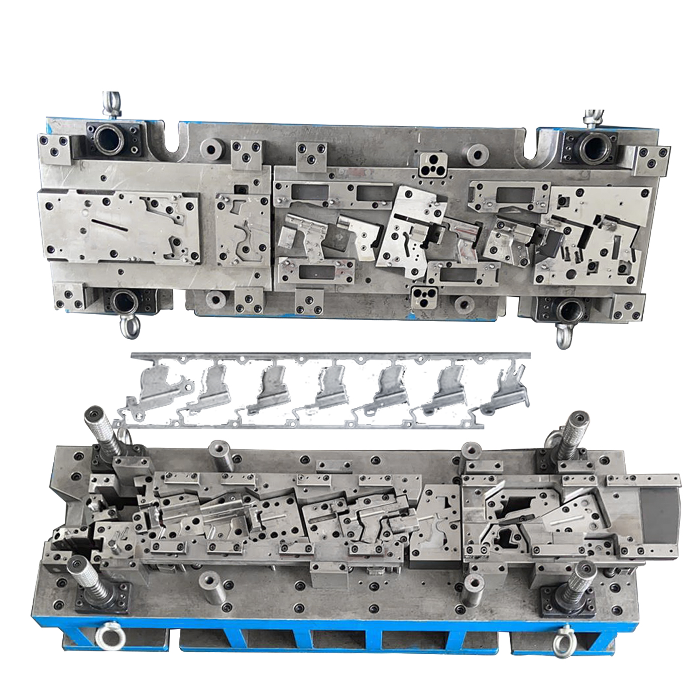
প্রতিযোগিতামূলক থাকার জন্য এবং কম খরচের লক্ষ্যগুলি পূরণ করতে, প্রকৌশল দল ডিজাইনটিকে প্রগতিশীল ডাই স্ট্যাম্পিং সমাধানে রূপান্তর করার প্রস্তাব দিয়েছিল। বছরে 250,000 ইউনিট করে উৎপাদনের পূর্বাভাসের সাথে, অটো মেটাল স্ট্যাম্পিং এর অর্থনীতি দ্রুত নজরে আসে। দলটি উৎপাদনযোগ্যতার জন্য ব্র্যাকেটটি পুনরায় ডিজাইন করতে একটি স্ট্যাম্পিং সরবরাহকারীর সাথে যৌথভাবে কাজ করে, বেঁকে যাওয়া, গর্তের অবস্থান এবং ক্যারিয়ার ডিজাইনের জন্য DFM নিয়মগুলির উপর মনোনিবেশ করে। ফলাফল? একটি 13-স্টেশন প্রগতিশীল ডাই যা খরচ এবং মান উভয় ক্ষেত্রেই উল্লেখযোগ্য উন্নতি নিয়ে এসেছে।
সিপিকে পরিবর্তন করা ডাই
কোন ব্যাপারটি পার্থক্য এনেছিল? প্রগতিশীল স্ট্যাম্পিং এ রূপান্তর শুধুমাত্র প্রক্রিয়া পরিবর্তন করা ছিল না - এটি ছিল দীর্ঘমেয়াদী নির্ভরযোগ্যতা এবং পারফরম্যান্স স্ট্যাম্পিংয়ের জন্য প্রতিটি বিস্তারিত অপ্টিমাইজ করা। প্রধান টুলিং পরিবর্তনগুলির মধ্যে ছিল:
- স্প্রিংব্যাক এবং ফাটল কমানোর জন্য বেঁকে যাওয়া ব্যাসার্ধ 1.5x উপকরণের পুরুত্বে বৃদ্ধি করা
- অংশের পুনরাবৃত্তি এবং উপকরণের প্রবাহ স্থিতিশীল রাখতে ড্র বিড যোগ করা
- ছিদ্রযুক্ত অপারেশনের জন্য পরিধান-প্রতিরোধী টুল স্টিলে স্যুইচ করে পাংচ পরিধান এবং বার্স হ্রাস করা
- ডাই-এ ট্যাপিং ইন্টিগ্রেট করে একটি মাধ্যমিক অপারেশন এবং স্ট্যাম্পড মেটাল অ্যাসেম্বলিগুলি স্ট্রিমলাইন করা
এই আপগ্রেডগুলি পরিমাপযোগ্য মানের উন্নতিতে ফলপ্রসূ হয়েছিল। ছিদ্র সত্যিকারের অবস্থানের জন্য সিপিকে (প্রক্রিয়া ক্ষমতা সূচক) 1.05 থেকে 1.67 এবং বেঁকে যাওয়া কোণের জন্য 1.10 থেকে 1.55 পর্যন্ত উন্নত হয়েছে। এর অর্থ হল নমিনাল মাত্রার চারপাশে আরও ঘন ক্লাস্টারিং, কম অস্পষ্ট অংশ এবং ডাউনস্ট্রিম অ্যাসেম্বলি সমস্যার কম ঝুঁকি - স্থিতিশীল, নিয়ন্ত্রিত স্ট্যাম্পিং এবং শক্তিশালী ডাই ডিজাইনের সরাসরি ফলাফল।
চক্র সময় এবং খরচ ফলাফল
| মেট্রিক | মেশিনযুক্ত (আগে) | প্রগ্রেসিভ স্ট্যাম্পড (পরে) |
|---|---|---|
| একক খরচ | $2.40 | $0.78 |
| চক্র সময় | 45 সেকেন্ড | 0.8 সেকেন্ড |
| খতিয়ানের হার | 1.2% | 0.25% |
| ছিদ্র সিপিকে | 1.05 | 1.67 |
| বেঁক কোণ Cpk | 1.10 | 1.55 |
ডিজাইন ফ্রিজ থেকে প্রথম ট্রায়াল পর্যন্ত মাত্র 10 সপ্তাহ বাস্তবায়ন সময় নিয়েছিল, দুটি যাথার্থ্য যাচাই লুপ এবং 300 পিস রান-অ্যাট-রেট ব্যবহার করে একটি PPAP লেভেল 3 জমা দেওয়া হয়েছিল। খরচ কমানো তৎক্ষণাৎ হয়েছিল - লক্ষ্য ভলিউমে প্রতি বছর প্রায় $400,000 এবং উন্নত Cpk নিয়ন্ত্রণ প্রক্রিয়া আরও ভালো করেছিল এবং ত্রুটি কমিয়েছিল। এটি শিল্পের সিদ্ধান্তকে প্রতিফলিত করে যে প্রগতিশীল স্ট্যাম্পিং কেবলমাত্র শক্তিশালী DFM এবং স্বয়ংক্রিয়তার সাথে যুক্ত হলে মানের উন্নতি করে খরচ 20% পর্যন্ত কমাতে পারে।
- ক্যারিয়ার ডিজাইন: প্রাথমিক পর্যায়ে ক্যারিয়ার প্রস্থ এবং পিচের উপর মনোনিবেশ বিকৃতি কমাতে এবং সব স্টেশনে জিনিসগুলি স্থিতিশীল রাখতে সাহায্য করেছিল।
- লুব নির্বাচন: উচ্চ কর্মক্ষমতা সম্পন্ন স্ট্যাম্পিং লুব্রিক্যান্টে পরিবর্তন করে ইস্পাত স্ট্যাম্পড অংশগুলির গলিং কমিয়েছিল এবং পৃষ্ঠের সমাপ্তি উন্নত করেছিল।
- সেন্সর স্থাপন: ডাই-এর ভিতরে মিসফিড সনাক্তকরণের জন্য সেন্সরগুলি ব্যয়বহুল দুর্ঘটনা রোধ করেছিল এবং স্ট্যাম্পড অ্যালুমিনিয়াম অংশ এবং ইস্পাত ব্র্যাকেটগুলির জন্য অপেরাশন সময় বাড়িয়েছিল।
প্রধান বিষয়: টুলিং অ্যামোর্টাইজেশন 70,000 ইউনিটের কমে অর্জিত হয়েছিল—অর্থাৎ সেই বিন্দুর পরে প্রতিটি অংশ খাঁটি সাশ্রয় দিয়েছিল, যা যে কোনও হাই-ভলিউম স্ট্যাম্পড মেটাল অ্যাসেম্বলিস প্রকল্পের জন্য দ্রুত পে-ব্যাক নিশ্চিত করেছিল।
এই পদ্ধতি পুনরাবৃত্তি করা শুধুমাত্র ব্র্যাকেটের জন্য সীমাবদ্ধ নয়। শীল্ড, কানেক্টর এবং অন্যান্য মেটাল স্ট্যাম্পিং গাড়ির অংশগুলি সমস্তই একই শৃঙ্খলাবদ্ধ DFM, টুলিং অপ্টিমাইজেশন এবং প্রক্রিয়া নিয়ন্ত্রণের সুবিধা পেতে পারে। পারফরম্যান্স স্ট্যাম্পিংয়ের উপর দৃষ্টি নিবদ্ধ করার মাধ্যমে এবং প্রগ্রেসিভ ডাই প্রযুক্তির সুবিধা নেওয়ার মাধ্যমে, আপনি খরচ, মান এবং লিড সময়ে অনুরূপ উন্নতি অর্জন করতে পারবেন—আপনার অটোমোটিভ স্ট্যাম্পিং চ্যালেঞ্জের জটিলতা যাই হোক না কেন।
পরবর্তীতে, আমরা আপনাকে একটি সরবরাহকারী মূল্যায়ন এবং RFQ চেকলিস্ট সরবরাহ করব যাতে আপনার পরবর্তী কাস্টম অটোমোটিভ মেটাল স্ট্যাম্পিং প্রকল্পটি দিন থেকে এই ধরনের ফলাফল দিতে পারে।
সাফল্যের জন্য সরবরাহকারী মূল্যায়ন এবং RFQ চেকলিস্ট
একটি অটোমোটিভ স্ট্যাম্পারের কাছে কী খুঁজছেন
আপনি যখন কাস্টম অটোমোটিভ মেটাল স্ট্যাম্পিং অংশগুলি, আপনি যে সরবরাহকারী বেছে নেন তা আপনার প্রকল্পটি সফল করে তুলবে কি না। কখনও কি নিজেকে দীর্ঘ তালিকার সাথে তুলনা করতে দেখেছেন মেটাল স্ট্যাম্পিং সার্ভিস প্রদানকারীদের মধ্যে কে আপনার প্রকৃত প্রয়োজন পূরণ করবে তা নিয়ে ভাবছেন? বৈশ্বিক নেতাদের কাছ থেকে শুরু করে আমার কাছাকাছি মেটাল স্ট্যাম্পিং অনুসন্ধানের মাধ্যমে, সিদ্ধান্তটি কয়েকটি গুরুত্বপূর্ণ কারকের উপর নির্ভর করে: সার্টিফিকেশন, প্রক্রিয়ার ক্ষমতা, প্রায়োগিক গভীরতা এবং মোট মালিকানা খরচ। চলুন এটিকে স্পষ্ট করি একটি পাশাপাশি তুলনা সারণির মাধ্যমে যাতে আপনি এক নজরে শক্তি নির্ণয় করতে পারেন।
| সরবরাহকারী | প্রত্যয়ন | টনেজ প্রেসের পরিসর | ডাই ডিজাইন/বিল্ড ইন-হাউস | পরিচালিত উপকরণ | সাধারণ সহনশীলতা (মিমি) | পিপিএপি লেভেল অভিজ্ঞতা | উৎপাদন সময় | যানবাহন দখল | টীকা |
|---|---|---|---|---|---|---|---|---|---|
| শাওয়ি মেটাল পার্টস সাপ্লায়ার চীন |
IATF 16949, ISO 9001 | 100–600 টন | হ্যাঁ | ইস্পাত, অ্যালুমিনিয়াম, ষ্টেইনলেস | ±0.05 | 1–5 | 8–16 সপ্তাহ | বিশ্বব্যাপী | ডাই-এর মধ্যে সেন্সিং, ডিএফএম সমর্থন, দ্রুত প্রোটোটাইপিং, কাস্টম অটোমোটিভ মেটাল স্ট্যাম্পিং বিশেষজ্ঞতা |
| গেস্ট্যাম্প উত্তর আমেরিকা মার্কিন যুক্তরাষ্ট্র/মেক্সিকো |
IATF 16949, ISO 9001 | ৩,০০০+ টন পর্যন্ত | হ্যাঁ | ইস্পাত, AHSS, অ্যালুমিনিয়াম | ±0.10 | 1–5 | ১০–১৬ সপ্তাহ | বিশ্বব্যাপী | বৃহদাকার, BIW, হট স্ট্যাম্পিং, OEM নিকটতা |
| মার্টিনরিয়া হেভি স্ট্যাম্পিং মার্কিন যুক্তরাষ্ট্র |
IATF 16949, ISO 9001 | ৩,৩০৭ টন পর্যন্ত | হ্যাঁ | ইস্পাত, AHSS | ±0.12 | 1–5 | ১০–১৬ সপ্তাহ | উত্তর আমেরিকা | ভারী গেজ, ক্র্যাশ স্ট্রাকচার, শক্তিশালী PM |
| গোশেন স্ট্যাম্পিং কোম্পানি মার্কিন যুক্তরাষ্ট্র |
আইএসও 9001 | 30–400 টন | হ্যাঁ | ইস্পাত, অ্যালুমিনিয়াম, পিতল | ±0.15 | 1–3 | ৪–৮ সপ্তাহ | মধ্য-পশ্চিম মার্কিন যুক্তরাষ্ট্র | দক্ষ, দ্রুত টুল পরিবর্তন, পরিষেবা/অ্যাফটারমার্কেট ফোকাস |
| লগান স্ট্যাম্পিংস ইনক মার্কিন যুক্তরাষ্ট্র |
আইএসও 9001 | 10–200 টন | হ্যাঁ | ইস্পাত, জং প্রতিরোধী, তামা | ±0.08 | 1–3 | ৪–৮ সপ্তাহ | মার্কিন যুক্তরাষ্ট্র | নির্ভুলতা, ছোট অংশ, উচ্চ Cp/Cpk, FAI প্যাকেজ |
| কোয়ালিটি মেটাল স্ট্যাম্পিং TN মার্কিন যুক্তরাষ্ট্র |
আইএসও 9001 | 400 টন পর্যন্ত | হ্যাঁ | ইস্পাত, অ্যালুমিনিয়াম | ±0.12 | 1–3 | 6–10 সপ্তাহ | দক্ষিণ-পূর্ব মার্কিন যুক্তরাষ্ট্র | নমনীয়, নির্মাণ, অঞ্চলভিত্তিক দক্ষতা |
লক্ষ্য করুন প্রতিটি সরবরাহকারী কীভাবে অনন্য শক্তি নিয়ে আসে। গতির প্রয়োজন এমন বৈশ্বিক প্রোগ্রামের ক্ষেত্রে, IATF 16949-স্তরের মান এবং শক্তিশালী মানের জন্য শাওয়ি স্পষ্টতই প্রতিদ্বন্দ্বিতা করে। অন্যদের মধ্যে, যেমন জেস্ট্যাম্প এবং মার্টিনরিয়া বৃহদাকার বা ভারী-গেজ প্রকল্পগুলিতে দক্ষতা দেখায়, যেখানে অঞ্চলভিত্তিক বিশেষজ্ঞরা পরিষেবা এবং অ্যাফটারমার্কেট পার্টসের জন্য দক্ষতা প্রদান করে। আপনি যাই খুঁজছিলেন কাস্টম অটোমোটিভ মেটাল স্ট্যাম্পিং সমর্থন। অন্যান্য, যেমন গেস্ট্যাম্প এবং মার্টিনরিয়া বৃহদাকার বা ভারী-গেজ প্রকল্পগুলিতে দক্ষ, যেখানে অঞ্চলভিত্তিক বিশেষজ্ঞরা পরিষেবা এবং অ্যাফটারমার্কেট পার্টসের জন্য দক্ষতা প্রদান করে। আপনি যাই খুঁজছিলেন আমার কাছাকাছি স্ট্যাম্পিং কোম্পানি বা ক কাস্টম মেটাল স্ট্যাম্পিং কোম্পানি বিশ্বব্যাপী পৌঁছানোর সাথে, আপনার প্রোগ্রামের প্রযুক্তিগত এবং যোগাযোগ প্রয়োজনীয়তা অনুযায়ী আপনার শর্টলিস্ট সাজান (সরবরাহকারী তুলনা গাইড) .
কোটেশন দ্রুত করার জন্য আরএফকিউ প্যাকেজ আইটেম
কোটেশন অনুরোধ করতে প্রস্তুত? একটি সম্পূর্ণ আরএফকিউ প্যাকেজ আপনাকে বিশ্বব্যাপী খেলোয়াড়দের কাছ থেকে একই ধরনের প্রতিক্রিয়া পেতে সাহায্য করে আমার কাছাকাছি মেটাল স্ট্যাম্পিং পরিষেবা . এগুলো অন্তর্ভুক্ত করুন:
- পূর্ণ জিডিএন্টি (জ্যামিতিক মাত্রা এবং সহনশীলতা) সহ আঁকা
- বার্ষিক এবং ইএইউ (প্রত্যাশিত বার্ষিক ব্যবহার) পরিমাণ
- লক্ষ্য মূল্য এবং খরচ ভাঙন (যদি পাওয়া যায়)
- সহনশীলতা ব্যতিক্রম বা মানের জন্য গুরুত্বপূর্ণ বৈশিষ্ট্যের তালিকা
- উপকরণ এবং আবরণ স্পেসিফিকেশন (SAE/ASTM মান সহ)
- প্রয়োজনীয় PPAP স্তর এবং নথিভুক্তিকরণের প্রত্যাশা
- পরিদর্শন এবং পরিমাপ পরিকল্পনা (গেজ ধারণা সহ)
- প্যাকিং, লেবেলিং এবং পরিচালনের প্রয়োজনীয়তা
- প্রোটোটাইপ এবং নমুনা পরিমাণের প্রয়োজনীয়তা
- ডেলিভারি ইনকোটার্মস এবং লজিস্টিক পছন্দ
প্রো টিপ: আপনার RFQ-এ গেজ ধারণা অন্তর্ভুক্ত করা এবং বিশেষ বৈশিষ্ট্য চিহ্নিত করা প্রস্তাবের ঝুঁকি কমায় এবং নিশ্চিত করে যে সরবরাহকারীরা শুরু থেকেই আপনার প্রকৃত প্রয়োজনীয়তা বুঝতে পারবে।
ক্ষমতা এবং মান যাচাই করার পদ্ধতি
ব্যবসা প্রদানের আগে— এটি যে কোনও বিশ্বজুড়ে সরবরাহকারী হোক বা আমার কাছাকাছি মেটাল স্ট্যাম্পার্স —একটি দ্রুত অডিট চালান। সাইট পরিদর্শন বা ভার্চুয়াল ট্যুরের সময় জিজ্ঞাসা করার জন্য এখানে কয়েকটি বুদ্ধিদায়ক প্রশ্ন রয়েছে:
- ডাই/টুল রক্ষণাবেক্ষণ কীভাবে ট্র্যাক করা হয় এবং সময়সূচী করা হয়?
- গুরুত্বপূর্ণ ডাইগুলির জন্য স্পেয়ার পাঞ্চ/ইনসার্টগুলির স্টক লেভেল কী?
- সদ্য চলমান হারের পরীক্ষা এবং ক্ষমতা ব্যবহারের প্রমাণ আপনি কীভাবে সরবরাহ করতে পারেন?
- উৎপাদনের মাধ্যমে কীভাবে উপকরণগুলি সার্টিফাইড এবং ট্র্যাক করা হয়?
- অন্তর্বর্তী পরিদর্শন এবং SPC সিস্টেমগুলি কী কী?
- জরুরি প্রকৌশল পরিবর্তনের উত্তর আপনি কত দ্রুত দিতে পারেন?
এই প্রশ্নগুলি আপনাকে বিপজ্জনক বিকল্পগুলি থেকে নির্ভরযোগ্য অংশীদারদের পৃথক করতে সাহায্য করে—আপনি যেটি খুঁজছেন তার বিবেচনা না করেই অটোমোটিভ মেটাল স্ট্যাম্পিং কোম্পানি বৈশ্বিক পৌঁছানোর সাথে বা মূল্যায়ন করার সময় আমার কাছাকাছি মেটাল স্ট্যাম্পিং পরিষেবা একটি দ্রুত প্রকল্পের জন্য।
আপনার শর্টলিস্ট, তুলনামূলক তথ্য এবং একটি কঠোর আরএফকিউ চেকলিস্ট হাতে থাকার মাধ্যমে আপনি সুনিশ্চিত ও ঝুঁকি সচেতন স্তরে সরবরাহকারী নির্বাচনের প্রস্তুতি নিয়ে ফেলেছেন। পরবর্তীতে, আমরা আপনাকে আরএফকিউ থেকে উৎপাদন চালু করার জন্য কোনো দেরি বা অপ্রত্যাশিত ঘটনা ছাড়াই একটি বাস্তব সরবরাহ পরিকল্পনা সংক্রান্ত রূপরেখা প্রদান করব।
নির্ভরযোগ্য উৎপাদনের পরবর্তী পদক্ষেপ
আপনার 30-দিনের স্ট্যাম্পিং সরবরাহ পরিকল্পনা তৈরি করুন
কখনো কি নতুন অটোমোটিভ স্ট্যাম্পিং পার্টস প্রকল্প চালু করার জটিলতায় অস্বস্তিবোধ করেছেন? চিন্তা করুন এমন একটি পরিষ্কার সপ্তাহে সপ্তাহে রোডম্যাপের যা আপনাকে প্রাথমিক প্রয়োজনীয়তা থেকে শুরু করে প্রোটোটাইপ পার্টস পর্যন্ত নিয়ে যাবে—সাধারণ দেরি এবং ভুল ছাড়াই। এখানে আপনি কীভাবে এই গাইডের অন্তর্দৃষ্টি থেকে পদক্ষেপগুলি গ্রহণ করে কাস্টম অটোমোটিভ মেটাল স্ট্যাম্পিংয়ে সাফল্যের জন্য পরীক্ষিত 30-দিনের পরিকল্পনা বাস্তবায়ন করতে পারেন।
-
1ম সপ্তাহ: সংজ্ঞায়ন এবং নিশ্চিতকরণ
- বিস্তারিত পার্ট প্রিন্টগুলি একত্রিত করুন এবং CTQ (মানের জন্য সমালোচনামূলক) বৈশিষ্ট্যগুলি হাইলাইট করুন।
- আপনার অটোমোটিভ মেটাল পার্টসের জন্য প্রয়োজনীয় মেটাল গ্রেড, পুরুত্ব এবং যেকোনো বিশেষ কোটিং নিশ্চিত করুন।
- উচ্চ ঝুঁকির বৈশিষ্ট্যগুলি চিহ্নিত করুন— কম সহনশীলতা, গভীর টানা বা কঠিন সমাপ্তি।
-
সপ্তাহ 2: DFM এবং প্রক্রিয়া লক-ইন
- আপনার প্রকৌশল এবং সরবরাহকৃত দলগুলির সাথে একটি DFM (ডিজাইন ফর ম্যানুফ্যাকচারেবিলিটি) ওয়ার্কশপ চালান।
- অংশের জ্যামিতি এবং পরিমাণের উপর ভিত্তি করে স্ট্যাম্পিং প্রক্রিয়া পথ হিমায়িত করুন—প্রগতিশীল ডাই, স্থানান্তর বা হাইব্রিড।
- নমুনা পরিদর্শন ফর্ম সংগ্রহ করুন এবং প্রধান বৈশিষ্ট্যগুলির জন্য ক্ষমতা লক্ষ্য নির্ধারণ করুন।
-
সপ্তাহ 3: RFQ এবং সরবরাহকারী জড়িত হওয়া
- সম্পূর্ণ প্যাকেজ সহ আরএফকিউ ইস্যু করুন: চিত্র, পরিমাণ, স্পেসিফিকেশন এবং মানের প্রয়োজনীয়তা।
- তালিকাভুক্ত সরবরাহকারীদের সাথে কল শিডিউল করুন প্রযুক্তিগত প্রশ্নগুলি পরিষ্কার করতে এবং ক্ষমতা যাচাই করতে।
- প্রতিক্রিয়াগুলি কেবল মূল্যের উপর নয়, পিপিএপি প্রস্তুতি এবং সরঞ্জাম কৌশলের উপর ভিত্তি করে তুলনা করুন।
-
সপ্তাহ 4: ডাউনসিলেক্ট এবং প্রোটোটাইপ
- শক্তিশালী অটোমোটিভ মেটাল ষ্ট্যাম্পিং প্রক্রিয়া নিয়ন্ত্রণ সহ সরবরাহকারীদের অডিট এবং তথ্যসূত্র পর্যালোচনা করুন।
- আপনার প্রোটোটাইপ ক্রয় অর্ডার দিন এবং ট্রায়াউট এবং যাথার্থ্য যাচাইয়ের পরিকল্পনার সাথে সমন্বয় করুন।
- শেখা অধিবেশন পর্যালোচনার প্রস্তুতি এবং ভবিষ্যতের DFM মান আপডেটের জন্য প্রস্তুতি নিন।
প্রধান সাফল্যের কারণ: যখন DFM সিদ্ধান্ত এবং PPAP প্রয়োজনীয়তা প্রথম দিন থেকে সামঞ্জস্যপূর্ণ হয় তখন সবচেয়ে দ্রুততম এবং নির্ভরযোগ্য চালু হয়। মানের বিষয়টিকে পরবর্তী চিন্তা হিসাবে নিন না - প্রতিটি ক্রয় এবং ডিজাইন সিদ্ধান্তে এটি অন্তর্ভুক্ত করুন।
গোড়ায় DFM এবং PPAP নিশ্চিত করুন
যখন আপনি জটিল অটো স্ট্যাম্পিং প্রকল্পের সাথে কাজ করছেন, ডিএফএম এবং পিপিএপি ডেলিভারেবলগুলি প্রাথমিকভাবে লক করা হল আপনার সবচেয়ে বড় প্রতিরোধ ব্যবস্থা যে কোনও পর্যায়ে অপ্রত্যাশিত ঘটনা ঘটার বিরুদ্ধে। ধরুন আপনি একটি নতুন ইভি ব্র্যাকেটের জন্য প্রস্তুতি নিচ্ছেন - আপনার স্ট্যাম্পিং অংশীদারকে ডিজাইন পর্যায়ে জড়িয়ে আপনি ইস্পাত কাটার আগে খরচের মেশিন পরিবর্তন এবং উৎপাদনযোগ্যতা সমস্যাগুলি কমিয়ে দিতে পারেন। এই প্রতিরোধমূলক পদ্ধতি শুধুমাত্র নেতৃত্বের সময়কে কমায় না, বরং আপনার অটোমোটিভ মেটাল প্রেসিং সমস্ত প্রয়োজনীয়তা এবং গ্রাহকের প্রয়োজনীয়তা পূরণ করছে কিনা তা নিশ্চিত করে।
শীর্ষ সরবরাহকারী - যেমন শাওয়ি মেটাল পার্টস সাপ্লায়ার - প্রতিটি পদক্ষেপে ইঞ্জিনিয়ারিং এবং মান সমর্থন একীভূত করে দেয়। তাদের আইএটিএফ 16949 সার্টিফিকেশন, দ্রুত প্রোটোটাইপিং এবং উন্নত সিএই বিশ্লেষণের মাধ্যমে আপনাকে ডিজাইন এবং বৃহৎ উৎপাদনের মধ্যে ফাঁক পূরণ করতে সাহায্য করে, বিশেষত যখন সময়সীমা কম থাকে এবং মানের মান অবশ্যই পালন করতে হয়।
আপনার ডেস্কে দ্রুত প্রোটোটাইপ পার্টস পান
প্রোটোটাইপের জন্য গতি অত্যন্ত গুরুত্বপূর্ণ। এই পরিকল্পনা অনুসরণ করলে আপনি এক মাসের মধ্যে উৎপাদন-উদ্দেশ্যযুক্ত নমুনা হাতে পাবেন—পরীক্ষামূলক ফিটিং, কার্যকরী পরীক্ষা এবং প্রাথমিক যাথার্থ্যের জন্য প্রস্তুত। যে অংশীদার এতটা দ্রুত গতিতে কাজ করতে পারবেন, তাঁর প্রয়োজন হলে শাওই মেটাল পার্টস সাপ্লায়ার এমন এক নাম যা তাদের দ্রুত সরবরাহ এবং শক্তিশালী মান নিয়ন্ত্রণের জন্য পরিচিত। কাস্টম অটোমোটিভ মেটাল স্ট্যাম্পিং ব্র্যাকেট, শিল্ড এবং কানেক্টরের জন্য সমাধানের ক্ষেত্রে তাদের সংস্থান কেন্দ্র ব্যবহারিক উদাহরণ এবং প্রযুক্তিগত অন্তর্দৃষ্টি সরবরাহ করে যা আপনার সংক্ষিপ্ত তালিকার সাথে তাদের ক্ষমতা তুলনা করতে সাহায্য করবে।
আপনি যেখানেই ক্রয় করুন না কেন—বৈশ্বিক স্তরে বা নিকটবর্তী স্থান থেকে অটো স্ট্যাম্পিংয়ের দক্ষতা খুঁজছেন—সর্বদা প্রকৌশল দক্ষতা, পিপিএপি অনুশাসন এবং প্রোটোটাইপ থেকে পূর্ণ উৎপাদনে পরিসর বাড়ানোর ক্ষমতার ভিত্তিতে সরবরাহকারীদের তুলনা করুন। আপনার পছন্দের ঝুঁকি কমানোর জন্য কেস স্টাডি, নমুনা নথি এবং রেফারেন্সের জন্য অনুরোধ করতে দ্বিধা করবেন না।
শেখা পাঠ: সেরা স্ট্যাম্পিং প্রকল্পগুলি প্রতিটি নির্মাণ থেকে শেখা পাঠ ধরে রাখে এবং সেগুলোকে DFM মান এবং ভবিষ্যতের RFQ-এ পুনরায় প্রয়োগ করে। অবিচ্ছিন্ন উন্নতিই হল গাড়ির ধাতব স্ট্যাম্পিং প্রকল্পে ভালো এবং দুর্দান্ত হওয়ার মধ্যে পার্থক্য নির্ধারণ করে।
পদক্ষেপ গ্রহণের জন্য প্রস্তুত? আপনার টেমপ্লেট হিসাবে এই 30-দিনের পরিকল্পনা ব্যবহার করুন, জটিল বা জরুরি প্রকল্পের জন্য Shaoyi-এর মতো বিশ্বস্ত অংশীদারদের সহায়তা নিন এবং সবসময় ভবিষ্যতের প্রোগ্রামের জন্য কী কাজ করেছে (এবং কী কাজ করেনি) তা নথিভুক্ত করুন। এই পদক্ষেপগুলির সাহায্যে, আপনি নির্ভরযোগ্য এবং পুনরাবৃত্তিমূলক উৎপাদনের জন্য প্রস্তুত হয়ে যাবেন - ভবিষ্যতে আপনার গাড়ির ধাতব স্ট্যাম্পিং প্রক্রিয়া কতটা চাপপূর্ণ হলেও তা সম্ভব হবে।
প্রায়শই জিজ্ঞাসিত প্রশ্নাবলী
1. কাস্টম অটোমোটিভ মেটাল স্ট্যাম্পিং কী এবং গাড়িতে এর ব্যবহার কীভাবে হয়?
কাস্টম অটোমোটিভ মেটাল স্ট্যাম্পিং হল সমতল ধাতব শীটগুলিকে বিশেষ ডাই এবং প্রেস ব্যবহার করে নির্দিষ্ট যানবাহন অ্যাপ্লিকেশনের জন্য নির্ভুল, জটিল অংশে গঠনের প্রক্রিয়া। এটি ব্র্যাকেট, ক্লিপ, শিল্ড, পুনর্বলিষ্কৃতকরণ এবং টার্মিনালসহ উপাদানগুলি উত্পাদনের জন্য ব্যবহৃত হয়, আধুনিক যানবাহনে গাঠনিক অখণ্ডতা এবং বৈদ্যুতিক কার্যকারিতা সমর্থন করে।
2. আমার অটোমোটিভ পার্টের জন্য কীভাবে সঠিক স্ট্যাম্পিং প্রক্রিয়া নির্বাচন করবেন?
সঠিক স্ট্যাম্পিং প্রক্রিয়া নির্বাচন করা অংশের জ্যামিতি, উপাদানের পুরুতা, প্রয়োজনীয় সহনশীলতা এবং উৎপাদন পরিমাণের উপর নির্ভর করে। প্রগ্রেসিভ ডাই স্ট্যাম্পিং উচ্চ পরিমাণের, পুনরাবৃত্তিমূলক অংশের জন্য আদর্শ, যেখানে ট্রান্সফার বা ডিপ ড্র স্ট্যাম্পিং জটিল বা গভীর-গঠিত উপাদানগুলির জন্য উপযুক্ত। ডিজাইনের প্রয়োজনীয়তা পর্যালোচনা করে এবং অভিজ্ঞ সরবরাহকারীদের সাথে পরামর্শ করে অপটিমাল প্রক্রিয়া নির্বাচন নিশ্চিত করা হয়।
3. অটোমোটিভ মেটাল স্ট্যাম্পিং-এ কোন উপাদান এবং কোটিং সাধারণত ব্যবহৃত হয়?
অটোমোটিভ মেটাল স্ট্যাম্পিং-এ প্রায়শই উচ্চ-শক্তি সম্পন্ন ইস্পাত (HSLA, DP, মার্টেনসিটিক), হালকা ওজনের জন্য অ্যালুমিনিয়াম খাদ, ক্ষয় এবং তাপ প্রতিরোধের জন্য স্টেইনলেস স্টিল এবং বৈদ্যুতিক অংশগুলির জন্য তামার খাদ ব্যবহৃত হয়। গ্যালভানিজড, ই-কোট এবং পাউডার কোটের মতো আবরণ ক্ষয় প্রতিরোধ এবং দীর্ঘতা বাড়াতে সাহায্য করে, যেখানে প্রয়োজনীয় শক্তি, আকৃতি দেওয়ার সামর্থ্য এবং পরিবেশগত প্রকাশের উপর ভিত্তি করে উপকরণের পছন্দ করা হয়।
4. কিভাবে আমি স্ট্যাম্পড অটোমোটিভ অংশগুলির মান এবং নিয়ম মেনে চলা নিশ্চিত করতে পারি?
IATF 16949, APQP এবং PPAP এর মতো শক্তিশালী পদ্ধতির মাধ্যমে অটোমোটিভ স্ট্যাম্পিং-এ মান নিশ্চিতকরণ অর্জন করা হয়। এই কাঠামোগুলি বিস্তারিত নথিভুক্তি, প্রক্রিয়া যাথার্থ্যায়ন, ক্ষমতা অধ্যয়ন এবং চলমান SPC পর্যবেক্ষণের প্রয়োজনীয়তা রাখে। প্রত্যয়িত সরবরাহকারীদের সাথে কাজ করা এবং গঠনবদ্ধ মান পরিকল্পনা অনুসরণ করে শিল্প মানদণ্ড এবং গ্রাহকের প্রয়োজনীয়তা মেনে চলা নিশ্চিত করে।
5. কাস্টম অটোমোটিভ মেটাল স্ট্যাম্পিংয়ের জন্য RFQ প্যাকেজে কী অন্তর্ভুক্ত করা উচিত?
বিস্তারিত চিত্র, জিডি এন্ড টি (GD&T), লক্ষ্য পরিমাণ, উপাদান এবং প্রলেপের বিবরণ, প্রয়োজনীয় পিপিএপি (PPAP) স্তর, পরিদর্শন পরিকল্পনা, প্যাকেজিং প্রয়োজনীয়তা এবং ডেলিভারি শর্তাবলী সহ একটি সম্পূর্ণ আরএফকিউ (RFQ) প্যাকেজ থাকা উচিত। স্পষ্ট প্রয়োজনীয়তা এবং বিশেষ বৈশিষ্ট্যগুলি সরবরাহ করা সরবরাহকারীদের সঠিক মূল্য প্রদানে সাহায্য করে এবং প্রকল্পের ঝুঁকি কমায়।