 ছোট ছোট ব্যাচ, উচ্চ মান। আমাদের তাড়াতাড়ি প্রোটোটাইপিং সার্ভিস যাচাইকরণকে আরও তাড়াতাড়ি এবং সহজ করে —

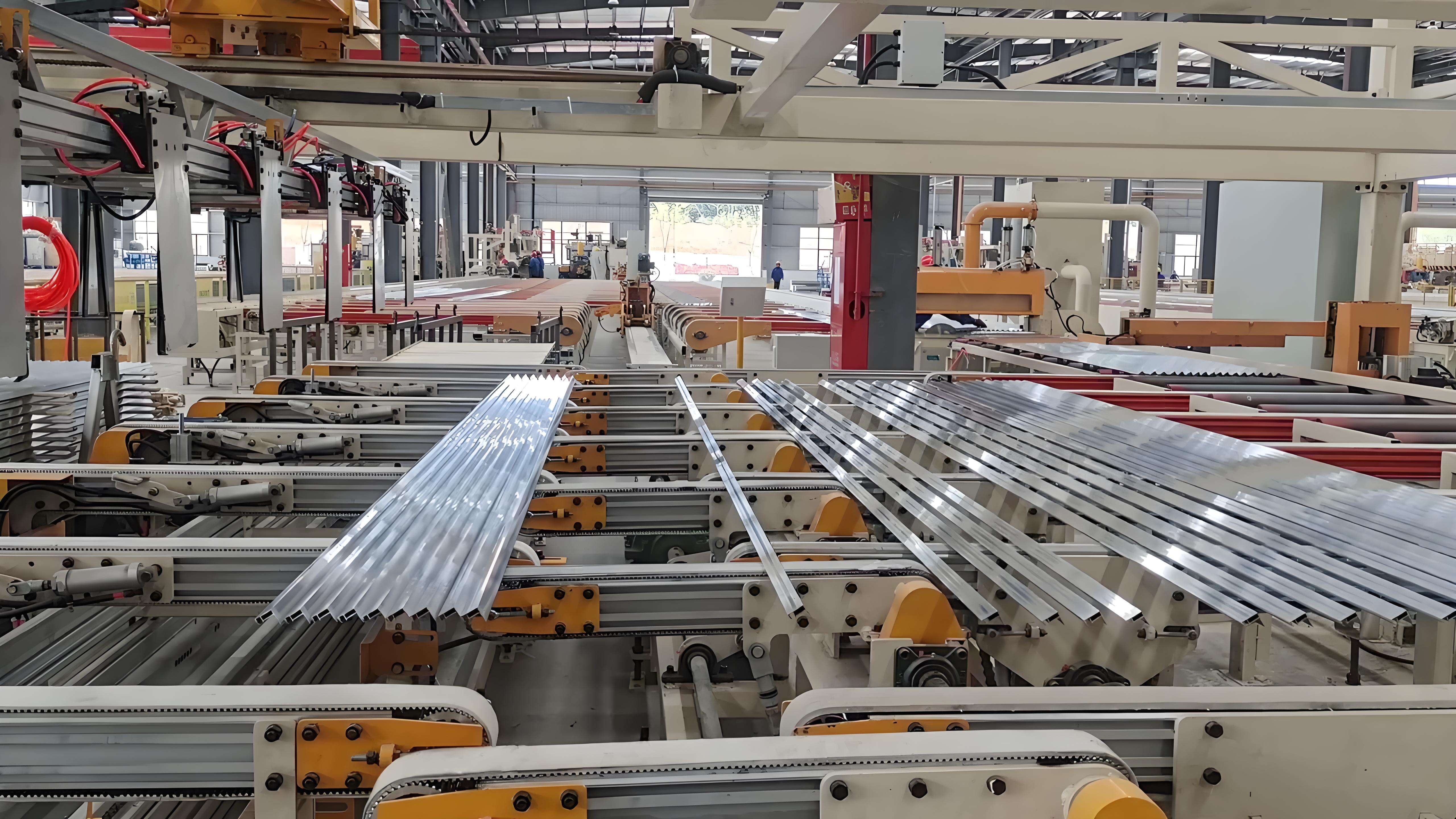
অটোমোটিভ অ্যালুমিনিয়াম এক্সট্রুশন ডিজাইন গাইড: SOP-এর জন্য 9 পদক্ষেপ
পদক্ষেপ 1: যানবাহন এবং প্রোগ্রাম লক্ষ্যগুলিকে পরিমাপযোগ্য এক্সট্রুশন প্রয়োজনীয়তায় অনুবাদ করুন
পারফরম্যান্স এবং প্যাকেজিং লক্ষ্য সংজ্ঞায়িত করুন
যখন আপনি একটি অটোমোটিভ অ্যালুমিনিয়াম এক্সট্রুশন ডিজাইন প্রকল্প শুরু করেন, প্রথম পদক্ষেপ হল প্রশস্ত প্রোগ্রাম লক্ষ্যগুলিকে পরিষ্কার, পরিমাপযোগ্য প্রয়োজনীয়তায় পরিণত করা। জটিল শোনাচ্ছে? এটা হতে হবে না। আপনার যানবাহন সিস্টেম দল থেকে ক্র্যাশ নিরাপত্তা লক্ষ্য, স্থায়িত্বের প্রত্যাশা, NVH (শব্দ, কম্পন এবং কঠোরতা) সীমা, ক্ষয় প্রতিরোধের প্রয়োজনীয়তা এবং প্যাকেজিং সীমাবদ্ধতা সহ সমস্ত গুরুত্বপূর্ণ ইনপুট সংগ্রহ করে শুরু করুন। এই কারকগুলি আপনার অ্যালুমিনিয়াম এক্সট্রুশন প্রোফাইলগুলি সম্পর্কে আপনার প্রতিটি সিদ্ধান্তকে গঠন করবে।
- ক্র্যাশ লোড পাথ এবং শক্তি শোষণ লক্ষ্য
- স্থায়িত্ব এবং ক্লান্তি জীবনের প্রয়োজনীয়তা
- NVH এবং কম্পন সীমা
- ক্ষয় এবং পরিবেশগত প্রকোপ (রাস্তার লবণ, আর্দ্রতা ইত্যাদি)
- তাপ ব্যবস্থাপনা (বিশেষ করে EV ব্যাটারি আবরণের জন্য)
- স্থান দাবি এবং প্যাকেজিং এনভেলপ
- খরচ, আয়তন এবং উত্পাদন সংক্রান্ত সীমাবদ্ধতা
- অন্যান্য উপকরণের (ইস্পাত, কম্পোজিট, প্লাস্টিক) সাথে সংযোগ
- নিয়ন্ত্রক এবং অরিজিনাল ইকুইপমেন্ট ম্যানুফ্যাকচারার (ওইএম) মেনে চলার প্রয়োজনীয়তা
ধরুন আপনি একটি ইলেকট্রিক ভেহিকলের জন্য ব্যাটারি বাক্স ডিজাইন করছেন। আপনাকে ক্রাশওয়ার্থিনেস, থার্মাল ম্যানেজমেন্ট এবং করোশন প্রোটেকশনের সাথে খাপ খাইয়ে নিতে হবে—সবকিছু কমপক্ষে জায়গা এবং বাজেটের মধ্যে রেখে। এখানেই একটি শক্তিশালী অ্যালুমিনিয়াম এক্সট্রুশন ডিজাইন গাইড আপনার রোডম্যাপ হয়ে ওঠে।
এক্সট্রুশন বৈশিষ্ট্যে প্রয়োজনীয়তা ম্যাপ করুন
পরবর্তীতে, এই উচ্চ-পর্যায়ের লক্ষ্যগুলিকে নির্দিষ্ট এক্সট্রুশন বৈশিষ্ট্যে রূপান্তর করুন। উদাহরণস্বরূপ, যদি আপনার লক্ষ্য উচ্চ শক্তি শোষণ হয়, তাহলে আপনি বহু-কোষ নির্বাচন করতে পারেন এলুমিনিয়াম এক্সট্রুশন প্রোফাইল নির্দিষ্ট প্রাচীর পুরুতা সহ। যদি এনভিএইচ একটি সমস্যা হয়, তাহলে খাঁজের দূরত্ব এবং বিভাগের গভীরতা অত্যন্ত গুরুত্বপূর্ণ হয়ে ওঠে। এই প্রক্রিয়াটিই হল অ্যালুমিনিয়াম এক্সট্রুশন কী —আপনার প্রকৌশল প্রয়োজনীয়তা সঠিকভাবে পূরণ করে এমন অংশগুলি তৈরি করতে অ্যালুমিনিয়াম এক্সট্রুশন প্রক্রিয়া ব্যবহার করা।
| প্রোগ্রামের লক্ষ্য | এক্সট্রুশন বৈশিষ্ট্য |
|---|---|
| শক্তি শোষণ | মাল্টি-সেল জ্যামিতি, প্রাচীর পুরুতা অনুকূলিতকরণ |
| NVH নিয়ন্ত্রণ | অনুকূলিত পাঁজর স্থানচ্যুতি, আবদ্ধ বিভাগসমূহ |
| দ্বারা ক্ষয় প্রতিরোধ | সংকর নির্বাচন, প্রলেপ, অ্যানোডাইজিং |
| থার্মাল ম্যানেজমেন্ট | ফিনযুক্ত পৃষ্ঠ, উচ্চ পরিবাহিতা সংকর |
| সমাপ্তি এবং চেহারা | পৃষ্ঠ প্রস্তুতি, অ্যানোডাইজড বা রঙ সমাপ্তি |
প্রতিটি প্রয়োজনীয়তাকে একটি স্পষ্ট বৈশিষ্ট্যের সাথে সংযুক্ত করে, আপনি আপনার ডিজাইন দল এবং সরবরাহকারীদের জন্য স্পষ্টতা প্রদান করেন। বিশেষ করে যেহেতু অটোমোটিভ অ্যালুমিনিয়াম এক্সট্রুশন অ্যাপ্লিকেশন আরও জটিল হয়ে ওঠে, ব্যাটারি এনক্লোজার থেকে শুরু করে ক্র্যাশ স্ট্রাকচার এবং বডি রেনফোর্সমেন্ট পর্যন্ত [AEC ইন্টারঅ্যাকটিভ গাইড] .
2025 সালে নিয়ন্ত্রক এবং মান মানদণ্ড পালন
মান এবং নথিভুক্তিকরণের গুরুত্ব হেলায় উড়িয়ে দেবেন না। উপাদান এবং পরীক্ষা পদ্ধতির জন্য ISO/ASTM-এর মতো কনসেনসাস মান এবং মান ব্যবস্থার জন্য IATF 16949 উল্লেখ করুন। অনেক OEM-এর নিজস্ব প্রয়োজনীয়তা রয়েছে, তাই সমস্ত ধারণা এবং গ্রহণযোগ্যতা মানদণ্ড প্রাথমিকভাবে নথিভুক্ত করুন। এটি সরবরাহকারীদের RFQ প্রক্রিয়াকে সহজ করে তুলবে এবং পরবর্তীতে ব্যয়বহুল ভুল বোঝার হাত থেকে রক্ষা করবে।
- প্রতিটি কর্মক্ষমতা লক্ষ্যের জন্য গ্রহণযোগ্যতা মানদণ্ড নথিভুক্ত করুন
- নিরীক্ষা চেকপয়েন্ট নির্দিষ্ট করুন (জ্যামিতি, যান্ত্রিক বৈশিষ্ট্য, পৃষ্ঠতল সমাপ্তি)
- লক্ষ্যগুলিকে বৈশিষ্ট্য এবং পরীক্ষার সাথে সংযুক্ত করে এমন প্রয়োজনীয়তা ট্রেসেবিলিটি ম্যাট্রিক্স বজায় রাখুন
অনেক রকম আছে অ্যালুমিনিয়াম এক্সট্রুশন প্রকার —শক্ত, খোলা এবং আধা-খোলা—যার প্রত্যেকটির নিজস্ব শক্তি রয়েছে বিভিন্ন সাবসিস্টেমের জন্য। সঠিক ধরনটি প্রারম্ভে বেছে নেওয়া এবং আপনার প্রয়োজনীয়তার সাথে মিলিয়ে নেওয়া হল একটি মৌলিক পদক্ষেপ অ্যালুমিনিয়াম এক্সট্রুশন প্রক্রিয়া .
এই পদক্ষেপে স্পষ্টতা ডাই ডিজাইন এবং যাথার্থ্য যাচাইয়ের সময় ব্যয়বহুল প্রোফাইল পুনর্নির্মাণ প্রতিরোধ করে।
সংক্ষেপে বলতে হলে, আপনার অ্যালুমিনিয়াম এক্সট্রুশন প্রকল্পের শুরুতে একটি সুসংহত পদ্ধতি সফলতার জন্য প্রস্তুতি নিশ্চিত করে। গাড়ি পর্যায়ের লক্ষ্যগুলিকে কার্যকর এক্সট্রুশন প্রয়োজনীয়তায় রূপান্তর করে আপনি অপ্রত্যাশিত ঘটনা এড়াতে পারবেন এবং ধারণা থেকে SOP পর্যন্ত আপনার প্রোগ্রামটি সঠিক পথে রাখতে পারবেন।
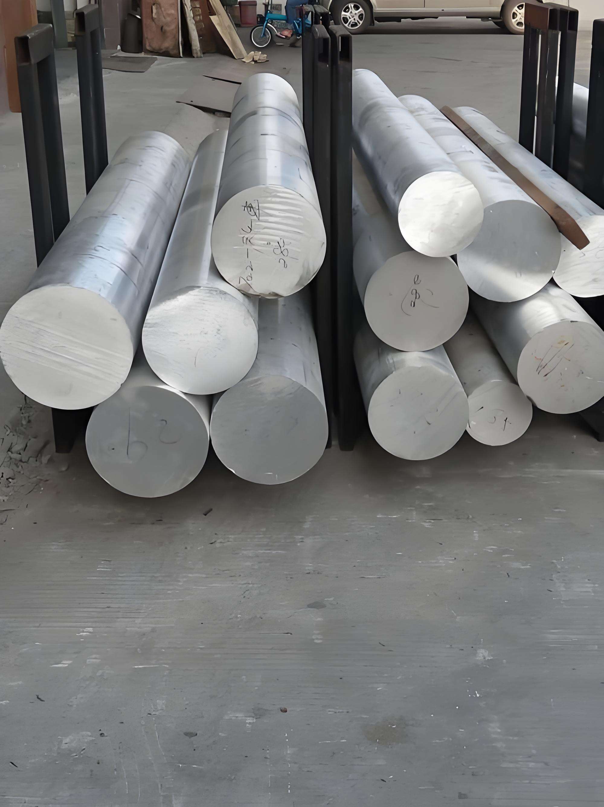
পদক্ষেপ ২: গাড়ি তৈরিতে সেরা অ্যালুমিনিয়াম এক্সট্রুশন মিশ্র ধাতু এবং টেম্পার নির্বাচন করুন
গাড়ি তৈরির জন্য মিশ্র ধাতু পরিবার নির্বাচন
যখন আপনি গাড়ি তৈরির অ্যালুমিনিয়াম এক্সট্রুশনের দুনিয়ায় প্রবেশ করবেন, তখন লক্ষ্য করবেন যে সব অ্যালুমিনিয়াম এক্সট্রুশন মিশ্র ধাতু সব সমান তৈরি হয় না। ধরুন আপনি একটি সংঘর্ষ কাঠামো বা একটি ব্যাটারি আবদ্ধকারী ডিজাইন করছেন - আপনি কীভাবে শক্তি, ক্ষয় প্রতিরোধ এবং উত্পাদনযোগ্যতা মধ্যে পছন্দ করবেন? উত্তরটি গাড়ি শিল্পে ব্যবহৃত সবচেয়ে সাধারণ খাদ পরিবারগুলি বোঝা থেকে শুরু হয়।
বেশিরভাগ ডিজাইনার শক্তি, এক্সট্রুডেবিলিটি এবং ক্ষয় প্রতিরোধের দুর্দান্ত ভারসাম্যের জন্য 6xxx সিরিজ (যেমন 6061 এবং 6063) নিয়ে কাজ করেন। এই আলুমিনিয়াম অ্যালোই এক্সট্রুশন পণ্যগুলি কাঠামোগত রেল, সাবফ্রেম এবং আবদ্ধকারী উপাদানগুলির জন্য প্রধান ভূমিকা পালন করে। আরও বেশি শক্তির দাবি রাখা অ্যাপ্লিকেশনের জন্য - পারফরম্যান্স যান বা নিরাপত্তা-সমালোচনামূলক সংঘর্ষ বীম চিন্তা করুন - 2xxx এবং 7xxx সিরিজ, যেমন 2024 এবং 7075 অ্যালুমিনিয়াম এক্সট্রুশন, কাজে লাগে। তবে, এই খাদগুলি তাদের নিজস্ব চ্যালেঞ্জ নিয়ে আসে, যেমন ক্ষয়ের প্রতি বৃদ্ধি পাওয়া ঝুঁকি বা আরও কঠিন এক্সট্রুশন এবং যোগদানের প্রক্রিয়া [অটোমোটিভ পেপারস] .
- আপনার অংশের জন্য কাঠামোগত, তাপীয় এবং সৌন্দর্যের প্রয়োজনীয়তা শনাক্ত করুন
- অগ্রাধিকারগুলি সারিবদ্ধ করুন: শক্তি, নমনীয়তা, পরিবাহিতা, ক্ষয়, সমাপ্তি এবং খরচ
- আপনার লক্ষ্যগুলির সাথে সামঞ্জস্য রেখে খাদ পরিবারগুলি ছাঁটাই করুন
- আপনার নির্বাচিত খাদের জন্য ডাই চাপ এবং প্রাচীর পুরুতা সীমার বিষয়ে আপনার সরবরাহকারীর সাথে পরামর্শ করুন
ধাতুর অবস্থা নির্ধারণ করা হচ্ছে ধাক্কা এবং স্থায়িত্বের জন্য
সঠিক ধাতুর অবস্থা নির্বাচন করা - তাপ চিকিত্সা এবং যান্ত্রিক প্রক্রিয়াকরণের সংমিশ্রণ - খাদটি নির্বাচন করার পাশাপাশি গুরুত্বপূর্ণ হতে পারে। ধাক্কা কাঠামোর জন্য, 6xxx বা 7xxx সিরিজের খাদগুলিতে T6 (সমাধান তাপ চিকিত্সা এবং কৃত্রিমভাবে বয়স্ক) এর মতো ধাতুর অবস্থা উচ্চ শক্তি প্রদান করে, কিন্তু কিছু নমনীয়তা হারাতে পারে। যে অংশগুলির জন্য আকৃতি দেওয়ার ক্ষমতা বা আঘাত শক্তি শোষণ গুরুত্বপূর্ণ, সেখানে একটি নরম ধাতুর অবস্থা বা আকৃতি দেওয়ার পরে তাপ চিকিত্সা নেওয়া উচিত। সবসময় আপনার সাথে সামঞ্জস্য পরীক্ষা করুন অ্যালুমিনিয়াম খাদের নিষ্কাশন প্রক্রিয়া এবং পরবর্তী অপারেশন।
শক্তি, ক্ষয় এবং সমাপ্তির ভারসাম্য বজায় রাখা
এটি কি ক্ষতিপূরণের মতো শোনাচ্ছে? প্রায়শই তাই। কঠিন খাদ অ্যালুমিনিয়ামের সুবিধাগুলি —যেমন 2xxx এবং 7xxx সিরিজের মত—অসাধারণ শক্তি এবং দৃঢ়তা অন্তর্ভুক্ত করে, যা উচ্চ-কার্যক্ষমতা সম্পন্ন অটোমোটিভ কাঠামোর জন্য এদের আদর্শ করে তোলে। তবে, বৃদ্ধিত মিশ্র ধাতু করা ক্ষয় প্রতিরোধের ক্ষমতা হ্রাস করতে পারে এবং যোগদান বা পৃষ্ঠতল সমাপ্তি জটিল করে তুলতে পারে। এটি অনেক ডিজাইনারদের স্থায়িত্ব এবং চেহারা বাড়ানোর জন্য পৃষ্ঠতল চিকিত্সা, যেমন অ্যানোডাইজিং বা পাউডার কোটিং ব্যবহার করতে হয়, বিশেষ করে বহিরঙ্গ অংশ বা ব্যাটারি আবদ্ধকারী জন্য।
আপনার মিশ্র ধাতু পরিবারগুলি সাধারণ অটোমোটিভ অ্যাপ্লিকেশনের সাথে মেলানোর জন্য এখানে একটি দ্রুত তুলনা রয়েছে:
| খাদ পরিবার | সাধারণ অটোমোটিভ ব্যবহার-কেস | মূল বৈশিষ্ট্য |
|---|---|---|
| 2xxx সিরিজ | ক্র্যাশ বীম, পারফরম্যান্স চ্যাসিস | উচ্চ শক্তি, মধ্যম ক্ষয় প্রতিরোধ (প্রায়শই ক্ল্যাড) |
| 5xxx সিরিজ | বডি প্যানেল, আবদ্ধকারী | ভালো ক্ষয় প্রতিরোধ, মধ্যম শক্তি |
| 6xxx সিরিজ | সাবফ্রেম, রেল, সাধারণ কাঠামো | ভারসাম্যযুক্ত শক্তি, নিষ্কাশনযোগ্যতা, ক্ষয় প্রতিরোধ ক্ষমতা |
| 7xxx সিরিজ | দুর্ঘটনা-সংক্রান্ত, উচ্চ-কার্যকারিতা ফ্রেম | অসাধারণ শক্তি, কম ক্ষয় প্রতিরোধ ক্ষমতা |
মনে রাখবেন, অ্যালুমিনিয়াম খাদ নিষ্কাশন আপনার সরবরাহকারীর সাথে সর্বদা যাচাই করে খাদ এবং টেম্পারের পছন্দগুলি নির্বাচন করা উচিত। তারা আপনার নির্বাচিত খাদ এবং টেম্পার আপনার প্রোফাইলের জ্যামিতি এবং প্রয়োজনীয় সহনশীলতার জন্য কার্যকর কিনা তা নিশ্চিত করতে পারবেন। প্রাথমিক সরবরাহকারীর প্রতিক্রিয়া ব্যয়বহুল পুনঃকাজ এড়াতে এবং নিশ্চিত করে যে নকশা উদ্দেশ্যের সাথে সামঞ্জস্য রেখে নিষ্কাশন প্রক্রিয়া চলছে।
প্রেস ক্ষমতা এবং আপনার প্রোফাইল জ্যামিতির জন্য অর্জনযোগ্য সহনশীলতা সরবরাহকারী দ্বারা নিশ্চিত হওয়ার পরেই খাদ এবং টেম্পার পছন্দগুলি চূড়ান্ত করা উচিত।
আপনার খাদ এবং টেম্পার সিদ্ধান্তগুলি নেওয়ার পরে, আপনি প্রোফাইল ডিজাইন এবং ডাই কৌশলগত পদক্ষেপে অগ্রসর হতে প্রস্তুত—যেখানে পরবর্তী পদক্ষেপে উৎপাদন সামর্থ্য এবং কার্যকারিতা একত্রিত হয়।
পদক্ষেপ 3: নকশার প্রোফাইলগুলি ডিজাইন করুন এবং উত্পাদনযোগ্যতার জন্য সঠিক ডাই কৌশল পরিকল্পনা করুন
প্রোফাইলের মৌলিক বিষয়: প্রাচীরের পুরুতা, ব্যাসার্ধ এবং প্রতিসাম্যতা
কখনও কি ভেবেছেন কেন কিছু অ্যালুমিনিয়াম এক্সট্রুশন প্রোফাইল উত্পাদন করা সহজ, অন্যগুলি অসীম সমস্যা তৈরি করে? উত্তরটি প্রায়শই অ্যালুমিনিয়াম এক্সট্রুশন ডিজাইনের মৌলিক বিষয়গুলির মধ্যে নিহিত থাকে। প্রতিসাম্যতা দিয়ে শুরু করুন - সমতুলিত প্রোফাইলগুলি কেবলমাত্র এক্সট্রুশন অ্যালুমিনিয়াম প্রক্রিয়ার সময় ভালো প্রবাহিত হয় না বরং বিকৃতি এবং অসম শীতলতা প্রতিরোধ করে। ধরুন যে একটি আকৃতি এক্সট্রুড করতে চাইছেন যার এক পাশ মোটা এবং একটি খুব পাতলা ফিন রয়েছে; আপনি সম্ভবত বক্রতা, ডাই ভাঙন বা অসম বৈশিষ্ট্যের সম্মুখীন হবেন। এক্সট্রুশন অ্যালুমিনিয়াম প্রক্রিয়া কিন্তু এছাড়াও বিকৃতি এবং অসম শীতলতা প্রতিরোধ করে। ধরুন যে একটি আকৃতি এক্সট্রুড করতে চাইছেন যার এক পাশ মোটা এবং একটি খুব পাতলা ফিন রয়েছে; আপনি সম্ভবত বক্রতা, ডাই ভাঙন বা অসম বৈশিষ্ট্যের সম্মুখীন হবেন।
- প্রাচীরের পুরুতা সমান রাখুন: মোটা-পাতলা সংক্রমণ বিকৃতি এবং পৃষ্ঠের ত্রুটির কারণ হতে পারে। আপনার ডিজাইনের মাধ্যমে সমসত্ত্ব প্রাচীরের উদ্দেশ্য রাখুন।
- প্রচুর ব্যাসার্ধ ব্যবহার করুন: ডাই এবং সম্পূর্ণ অংশ উভয়ের জন্যই শার্প কোণগুলি স্ট্রেস রাইজার হিসাবে কাজ করে। অভ্যন্তরীণ কোণগুলিতে ন্যূনতম ব্যাসার্ধ থাকা উচিত (যেমন, .015") এবং বহির্গামী কোণে অন্তত .020" [AEC ডিজাইন টিপস] .
- রিব এবং ওয়েবগুলি কৌশলগতভাবে স্থাপন করুন: শুধুমাত্র কঠোরতা বা সংযোজনের জন্য প্রয়োজনীয় স্থানে রিব যোগ করুন, অপ্রয়োজনীয় জটিলতা এড়িয়ে চলুন।
এই নির্দেশিকা অনুসরণ করে, আপনি কেবল উৎপাদনযোগ্যতা উন্নত করবেন না, বরং খরচও কমাবেন এবং ডাই ব্যর্থতা বা খতরা হওয়ার ঝুঁকি কমাবেন। এই নীতিগুলি যেকোনো ক্ষেত্রে মৌলিক এক্সট্রুশন ডাই ডিজাইন পরিশ্রম বাঁচান।
খোলা, আধা-খোলা বা কঠিন প্রোফাইল কখন বেছে নেবেন
সলিড, হোলো এবং সেমি-হোলো প্রোফাইলের মধ্যে বেছে নেওয়া একটি গুরুত্বপূর্ণ প্রাথমিক সিদ্ধান্ত। প্রতিটি ধরনের ভিন্ন কার্যকারিতা এবং সংযোজন কৌশলের সাথে মানানসই হয়:
- সলিড প্রোফাইল: দণ্ড, প্লেট এবং সংযোগকারী সহজ এবং দৃঢ় অংশগুলির জন্য সেরা। এগুলি খরচে কার্যকর এবং সরল পদ্ধতি ব্যবহার করে অ্যালুমিনিয়াম এক্সট্রুশন ডাইস .
- খাঁজযুক্ত প্রোফাইলস: পাইপ, ফ্রেম বা ব্যাটারি এনক্লোজারের মতো অভ্যন্তরীণ খাঁজসহ জটিল আকৃতির জন্য এটি আদর্শ। এগুলির জন্য আরও উন্নত মানের অ্যালুমিনিয়াম এক্সট্রুশন ডাই ডিজাইন, প্রায়শই অভ্যন্তরীণ ম্যানড্রেল বা ব্রিজসহ।
- আধা-খাঁজযুক্ত প্রোফাইলস: যেমন সরু ফাঁকা সহ চ্যানেলের মতো ডিজাইনের জন্য উপযোগী যা আংশিকভাবে একটি ফাঁকা স্থান বন্ধ করে। এগুলি জটিলতা এবং শক্তির মধ্যে ভারসাম্য বজায় রাখে।
ডাই প্রকারগুলির দ্রুত তুলনা এবং তাদের সাধারণ তুলনামূলক বৈশিষ্ট্য:
| ডাই টাইপ | প্রোফাইল উদাহরণ | প্রধান তুলনামূলক বৈশিষ্ট্য |
|---|---|---|
| ঠোট ডাই | বার, কোণ, সাধারণ সংযোগকারী | কম খরচ, উচ্চ শক্তি, সহজ নিষ্কাশন |
| সেমি-হোলো ডাই | সংকীর্ণ ফাঁক সহ চ্যানেল | মাধ্যমিক জটিলতা, বহুমুখী অ্যাপ্লিকেশন |
| পোর্টহোল/ব্রিজ ডাই (খালি) | টিউবিং, ফ্রেম সহ ফাঁকা স্থান | জটিল আকৃতি তৈরি করতে সাহায্য করে, ওয়েল্ড সিম প্রয়োজন, বেশি খরচ |
আপনাকে জিজ্ঞাসা করুন: আপনার অংশটি ওজন কমানোর বা ক্যাবল রাস্তা তৈরির জন্য অভ্যন্তরীণ খালি স্থান প্রয়োজন? অথবা একটি সাধারণ, কঠিন বিভাগ যথেষ্ট? এখানে প্রাথমিক সিদ্ধান্তগুলি শুধুমাত্র প্রভাবিত করে না অ্যালুমিনিয়াম এক্সট্রুশনের জন্য ডাই তবে সংযোগ এবং সংযোজনের নিম্নমুখী প্রক্রিয়াও।
জটিল অংশগুলির জন্য ডাই ডিজাইনের প্রয়োগ
এখন, চলুন বাস্তব চ্যালেঞ্জগুলি নিয়ে কথা বলি। জটিল প্রোফাইল - গভীর পকেট, পাতলা ফিনস বা অসম ভর চিন্তা করুন - যা করতে পারে অ্যালুমিনিয়াম এক্সট্রুশন ডাইস সামলাতে পারে। সাধারণ ভুলগুলি এড়ানোর জন্য এখানে কয়েকটি উপায়:
- গভীর, সরু বৈশিষ্ট্যগুলি সীমিত করুন: উচ্চ টং অনুপাত (খুব পাতলা, গভীর অংশগুলি) ডাই চাপ বাড়ায় এবং ভাঙ্গার ঝুঁকি বাড়ায় [AEC প্রধান বিবেচনা] .
- শূন্যস্থান এবং প্রাচীরগুলি ভারসাম্যপূর্ণ করুন: ধাতব প্রবাহ এবং শীতলতা সমানভাবে প্রচার করতে ভর এবং খোলা অঞ্চলগুলি প্রতিসম রাখুন।
- মেশিনিংয়ের জন্য পরিকল্পনা করুন: সহজ সেকেন্ডারি অপারেশন এবং অ্যাসেম্বলি সারিবদ্ধকরণের জন্য প্রচুর লিড-ইন এবং ডেটাম বৈশিষ্ট্য যোগ করুন।
- কার্যকারিতার জন্য প্রয়োজনীয় ন্যূনতম অংশটি আঁকুন।
- শুধুমাত্র অতিরিক্ত দৃঢ়তা বা মাউন্টিংয়ের প্রয়োজন হলে রিবস এবং ওয়েবস যোগ করুন।
- উৎপাদনযোগ্যতার জন্য প্রাচীর পুরুতা এবং ব্যাসার্ধ পরীক্ষা করুন।
- সমমিতি এবং ভারসাম্যপূর্ণ ভর বিতরণের জন্য পর্যালোচনা করুন।
- ডেটাম বৈশিষ্ট্য এবং মেশিনিং অনুমতিগুলি চূড়ান্ত করুন।
| সাধারণ ফাঁদ |
|---|
|
ডাই প্রকৌশলীদের সাথে প্রাথমিক সহযোগিতা করার মাধ্যমে অসমতুল প্রবাহ এবং বিকৃতি প্রতিরোধ করা যায়, যা টুল কাটের পরে সংশোধন করা খুব ব্যয়বহুল হয়ে থাকে।
এই নীতিগুলি অনুসরণ করে এবং আপনার সরবরাহকারীর দক্ষতা ব্যবহার করে, আপনি একটি আলুমিনিয়াম একস্ট্রুশন প্রোফাইল তৈরি করবেন যা সুদৃঢ়, উৎপাদনে কার্যকর এবং ডাউনস্ট্রিম অ্যাসেম্বলির জন্য প্রস্তুত। পরবর্তী পদক্ষেপ: ক্রাশওয়ার্থিনেস এবং শক্তি শোষণের জন্য আপনার প্রোফাইলগুলি কীভাবে প্রকৌশল করবেন—যেখানে অভ্যন্তরীণ ওয়েব এবং মাল্টি-সেল অংশগুলি আপনার সেরা বন্ধু হয়ে ওঠে।
পদক্ষেপ 4: মাল্টি-সেল এক্সট্রুশন দিয়ে ক্রাশ পারফরম্যান্স এবং শক্তি শোষণ অপ্টিমাইজ করুন
মাল্টি-সেল এক্সট্রুশন দিয়ে শক্তি শোষণ
ক্র্যাশওয়ার্থিনেসের জন্য ডিজাইন করার সময়, আপনি কখনো ভেবেছেন কীভাবে কাঠামোগত নির্মিত অ্যালুমিনিয়াম প্রোফাইলগুলি ব্যবহার করে বৃহদাকার শক্তি শোষণ করা যায়— তবে কীভাবে তাদের বিকৃতি নিয়ন্ত্রিত এবং পূর্বাভাসযোগ্য রাখা যায়? এর উত্তর হল অ্যালুমিনিয়াম নির্মিত প্রোফাইলের সঙ্গে সম্ভাব্য অনন্য জ্যামিতি ব্যবহার করা, বিশেষ করে বহু-কোষীয় ডিজাইনগুলি। ধরুন একটি ক্র্যাশ বাক্স বা বাম্পার বীম: একটি সাধারণ নলের পরিবর্তে, আপনি অভ্যন্তরীণ ওয়েবস সহ একটি বহু-কোষীয় অংশ ব্যবহার করুন। এই অভ্যন্তরীণ প্রাচীরগুলি আঘাতের শক্তিকে আরও দক্ষতার সঙ্গে বিতরণ এবং ছড়িয়ে দেয়, ধ্বংসাত্মক ব্যর্থতার ঝুঁকি কমায় এবং যাত্রী কক্ষের ভিতরে প্রবেশকে সীমিত করে।
গবেষণায় দেখা গেছে যে বহু-কোষীয় ষড়ভুজাকার নল, উদাহরণস্বরূপ, শক্তি শোষণের পরিমাণ দ্রুত বৃদ্ধি করতে পারে এবং অক্ষীয় চাপের ভার সহ স্থিতিশীল বিকৃতি অবস্থা বজায় রাখতে পারে। কোষের আকার, প্রাচীরের পুরুতা এবং অভ্যন্তরীণ জালিকার সংখ্যা পরিমাপ করে শক্তি শোষণ (EA), সর্বোচ্চ চাপ বল (PCF), এবং নির্দিষ্ট শক্তি শোষণ (SEA) -এর মধ্যে ভারসাম্য নিয়ন্ত্রণ করা যেতে পারে, যা ধাক্কা সহনশীলতার প্রধান মাপকাঠি। [PLOS ONE] নিয়ন্ত্রণের এই ধরনের স্তর হল উচ্চ-কার্যকারিতা সম্পন্ন অ্যালুমিনিয়াম এক্সট্রুশনের শিল্প প্রয়োগের একটি প্রধান বৈশিষ্ট্য, যেখানে নিরাপত্তা এবং পুনরাবৃত্তি অত্যন্ত গুরুত্বপূর্ণ।
- বহু-কোষীয় অংশসমূহ: শক্তি অপচয় বৃদ্ধি করুন এবং সার্বিক বাঁকানো প্রতিরোধ করুন
- নির্দিষ্ট প্রাচীরের পুরুতা: আবশ্যক স্থানে দৃঢ়তা বৃদ্ধি করুন, অন্য জায়গায় ওজন কমান
- অভ্যন্তরীণ পাঁজর/জালিকা: ভাঁজ হওয়াকে স্থিতিশীল করুন, ক্রমান্বয়ে ভেঙে পড়ার প্রবণতা বৃদ্ধি করুন
ট্রিগার এবং চাপ শুরু করার ডিজাইন করা
টেকনিক্যাল শোনাচ্ছে? এটি আসলে একটি ব্যবহারিক উপায় যা আপনার এক্সট্রুডেড ফ্রেম ক্র্যাশের সময় যেভাবে উদ্দেশ্য করা হয়েছে ঠিক সেভাবে বিকৃত হওয়া নিশ্চিত করে। ছিদ্র, নটচ বা স্থানীয় পাতলা করার মতো জ্যামিতিক বৈশিষ্ট্য যোগ করে, আপনি স্থানগুলিতে ভাঁজ শুরু করার জন্য ক্রাশ ইনিশিয়েটর তৈরি করতে পারেন। এটি অচেনা গ্লোবাল বেঁকে যাওয়া বা ফেটে যাওয়া এড়ায় এবং পরিবর্তে স্থিতিশীল, একরুপ ডিফরমেশন ঘটায়। AA6061 এবং AA6060 এক্সট্রুডেড স্ট্রাকচারাল অ্যালুমিনিয়াম দিয়ে গবেষণায় দেখা গেছে যে ভালোভাবে স্থাপিত ইনিশিয়েটর পিক ক্রাশ লোড 18% কমাতে পারে এবং শক্তি শোষণের দক্ষতা 50% বাড়াতে পারে [ScienceDirect] .
- ক্রাশ ইনিশিয়েটর: নিম্ন, পুনরাবৃত্তিযোগ্য লোডে ভাঁজ শুরু করার জন্য স্থানীয় বৈশিষ্ট্য
- প্রগ্রেসিভ ভাঁজ: প্রায় ধ্রুবক বল বজায় রাখে, নিরাপত্তা উন্নত করে
- জ্যামিতিক বিচ্ছিন্নতা: ডিফরমেশন প্যাটার্ন নিয়ন্ত্রণের জন্য ছিদ্র, স্লট বা খাঁজ
আটাচমেন্ট এবং লোড-পাথ কন্টিনিউইটি
কিন্তু ক্র্যাশওয়ার্থিনেস শুধুমাত্র প্রোফাইল নিয়ে নয়—এটি শক্তি গোটা কাঠামোর মধ্যে কীভাবে ছড়িয়ে পড়ে তা নিয়ে। শক্তিশালী সংযোগস্থল এবং স্পষ্ট লোড পথ বল সুরক্ষিতভাবে গাড়ির প্রধান কাঠামোতে স্থানান্তরিত হওয়া নিশ্চিত করে, অসময়ে ছিঁড়ে যাওয়া বা অপ্রত্যাশিত ব্যর্থতার ঝুঁকি কমিয়ে আনে। মাউন্টিং স্থানগুলিতে পুরু অংশ বা সুদৃঢ়ীকৃত অঞ্চল একত্রিত করুন এবং সর্বদা অনুকলন এবং প্রাকৃত পরীক্ষা দিয়ে সংযোগস্থলের অখণ্ডতা যাচাই করুন।
- সুদৃঢ়ীকৃত সংযোগস্থল: ক্র্যাশ লোডের অধীনে প্রারম্ভিক বিচ্ছিন্নতা প্রতিরোধ করুন
- স্পষ্ট লোড পথ: গুরুত্বপূর্ণ অঞ্চলগুলি (যেমন ব্যাটারি, যাত্রী কোষ) থেকে শক্তি সরিয়ে নিন
- অনুকলন এবং কুপন পরীক্ষা: পূর্ণ মাপের নির্মাণের আগে প্রকৃত পরিস্থিতিতে প্রদর্শন নিশ্চিত করুন
ক্র্যাশ অপটিমাইজেশন চেকলিস্ট: কার্যক্রম অনুযায়ী বৈশিষ্ট্য
-
উদ্বোধন:
- ক্রাশ উদ্বোধক (ছিদ্র, নটচ, পাতলা অংশ)
- নিয়ন্ত্রিত বাঁকানোর জন্য প্রি-ভাঁজ করা অঞ্চল
-
প্রসার:
- স্থিতিশীল প্রগতিশীল ভাঁজ করার জন্য মাল্টি-সেল জ্যামিতি
- স্থানীয় বাঁকা প্রতিরোধের জন্য অভ্যন্তরীণ পাঁজর/ওয়েবস
- শক্তি শোষণের সামঞ্জস্য করার জন্য প্রাচীরের পুরুতা অনুকূলিত করা
-
সংযুক্তিঃ
- জোরদার মাউন্টিং অঞ্চল
- সংলগ্ন কাঠামোতে সরাসরি লোড স্থানান্তর
প্রধান বিষয়: ভাঙন প্রতিরোধের সর্বোচ্চ মানের চেয়ে স্থিতিশীল, পুনরাবৃত্তিযোগ্য ভাঁজ এর উপর জোর দিন।
বুদ্ধিদীপ্ত এক্সট্রুশন জ্যামিতি, লক্ষ্যযুক্ত ট্রিগার এবং শক্তিশালী সংযোগ ডিজাইন একত্রিত করে আপনি গাড়ির নিরাপত্তার জন্য কাঠামোগত অ্যালুমিনিয়াম এক্সট্রুশনের সম্পূর্ণ সম্ভাবনা খুলতে পারবেন। এই পদ্ধতি নিয়ন্ত্রণমূলক প্রয়োজনীয়তা পূরণের পাশাপাশি হালকা ও নির্ভরযোগ্য সমাধান প্রদানে অপরিহার্য, যা আধুনিক অ্যালুমিনিয়াম এক্সট্রুডেড প্রোফাইলগুলি সংজ্ঞায়িত করে। পরবর্তীতে, আমরা কীভাবে NVH এবং মাত্রিক স্থিতিশীলতা নিয়ন্ত্রণ করব তা দেখব—যা চলাচলের গুণগত মান এবং দীর্ঘমেয়াদী স্থায়িত্বের জন্য অপরিহার্য।
ধাপ 5: স্মার্ট সহনশীলতা এবং পরিদর্শন কৌশলগুলির মাধ্যমে NVH এবং মাত্রিক স্থিতিশীলতা নিয়ন্ত্রণ করুন
NVH-সচেতন রিবিং এবং সেকশন টিউনিং
যখন আপনি একটি আধুনিক যানবাহনের চারপাশে হাঁটছেন, আপনি কি কখনও লক্ষ্য করেছেন কীভাবে শান্ত এবং মসৃণ ভাবে চলছে যানবাহনটি, খারাপ রাস্তাতেও? এটি কোনও দুর্ঘটনা নয় - এটি নিখুঁত NVH (শব্দ, কম্পন এবং কঠোরতা) প্রকৌশলের ফলাফল, যা গুরুত্বপূর্ণ কাঠামোতে ব্যবহৃত হয়। যদি আপনি আপনার অ্যালুমিনিয়াম এক্সট্রুশন ডিজাইনে NVH উপেক্ষা করেন, তবে প্রায়শই ব্যয়বহুল "ব্যান্ড-এইডস" যোগ করতে হবে, যেমন ভারী মাস্টিক প্যাচ বা ফেনা ইনসার্ট যা বৃদ্ধি করতে পারে এক্সট্রুশন শেপস ব্যবহৃত হয়। যদি আপনি আপনার অ্যালুমিনিয়াম এক্সট্রুশন ডিজাইনে NVH উপেক্ষা করেন, তবে প্রায়শই ব্যয়বহুল "ব্যান্ড-এইডস" যোগ করতে হবে, যেমন ভারী মাস্টিক প্যাচ বা ফেনা ইনসার্ট যা বৃদ্ধি করতে পারে অ্যালুমিনিয়াম এক্সট্রুশন ওজন এবং সংযোজন শ্রম [মোবিলিটি ইঞ্জিনিয়ারিং টেক] .
পরিবর্তে, আপনার প্রোফাইলের রিব প্যাটার্ন এবং অনুচ্ছেদের গভীরতা সমন্বয় করে শুরু করুন যাতে অতিসংবেদনশীল ব্যান্ডগুলি থেকে অনুনাদ ফ্রিকোয়েন্সিগুলি সরে যায় - এটিকে গিটার স্ট্রিংয়ের মতো সমন্বয় করার কথা ভাবুন। রিব স্পেসিং সামঞ্জস্য করে, আপনি প্যানেলের অংশগুলি ভেঙে দিতে পারেন যা অন্যথায় নির্দিষ্ট ফ্রিকোয়েন্সিতে "গান গাইবে"। উদাহরণস্বরূপ, একটি গভীর বিভাগ বা একটি বন্ধ বাক্স ডিজাইন স্বাভাবিকভাবেই দৃঢ়তর হবে এবং একটি প্রশস্ত, সমতল প্যানেলের তুলনায় কম কম্পনশীল হবে। অবিচ্ছিন্ন গ্যাস্কেট বা ডিকাপলিং ফ্ল্যাঞ্জের মতো যৌথ আলাদাকরণ বৈশিষ্ট্যগুলি আরও বিকিরণ শব্দ হ্রাস করতে পারে।
- মূল ফ্রিকোয়েন্সি থেকে অনুনাদ সরানোর জন্য রিব স্পেসিং অপ্টিমাইজ করুন
- দৃঢ়তা উন্নত করতে বিভাগের গভীরতা বাড়ান
- ভালো NVH এবং হ্রাস পাওয়ার জন্য বদ্ধ বিভাগ বা মাল্টি-সেল প্রোফাইল ব্যবহার করুন অ্যালুমিনিয়াম এক্সট্রুশন ওজন
- প্রয়োজনীয় স্থানে ড্যাম্পিং উপকরণ বা আলাদাকরণ স্তরের জন্য নকশা তৈরি করুন
দীর্ঘ প্রোফাইলের জন্য সহনশীলতা কৌশল
কি কখনও একটি দীর্ঘ এক্সট্রুডেড অ্যালুমিনিয়াম রেল সংযোজন করার চেষ্টা করেছেন এবং দেখেছেন যে এটি ঠিক মাপের নয়? সেখানেই বুদ্ধিমান সহনশীলতা পরিকল্পনা কাজে আসে। দীর্ঘের জন্য অ্যালুমিনিয়াম এক্সট্রুশন আকার পাশের রেল বা ব্যাটারি ট্রে বিম এর মতো অংশগুলির জন্য বাস্তব সোজা, মোচড় এবং বক্রতার সহনশীলতা নির্দিষ্ট করা অত্যন্ত গুরুত্বপূর্ণ। এগুলি শুধুমাত্র ডিজাইনের উদ্দেশ্যের উপর নির্ভর করে না, বরং আপনার সরবরাহকারীর প্রেস এবং শীতলীকরণ পদ্ধতির সাথে কী অর্জন করা যায় তার উপর ভিত্তি করে।
| প্রোফাইল বৈশিষ্ট্য | টলারেন্স কলআউট |
|---|---|
| সোজা | ডেটাম A এর তুলনায় (সাধারণত প্রধান মাউন্টিং মুখোমুখি) |
| টুইস্ট | দৈর্ঘ্য L এর উপর, ডেটাম A এর তুলনায় |
| গর্তের অবস্থান | ডেটাম A/B এর তুলনায় (গুরুত্বপূর্ণ সমবায় অবস্থানের জন্য) |
| মোট মাত্রা | রেফারেন্স স্ট্যান্ডার্ড এলুমিনিয়াম এক্সট্রুশন বেসলাইন সীমা নির্ধারণের জন্য |
ভুলবেন না: খুব কড়া সহনশীলতা খরচ এবং খুচরা অংশের পরিমাণ বাড়িয়ে দিতে পারে, অন্যদিকে ঢিলেঢালা সহনশীলতা খারাপ ফিটিং এবং NVH সমস্যার কারণ হতে পারে। আপনার অ্যালুমিনিয়াম এক্সট্রুশনের মাত্রা এবং উচ্চমানের প্রেস ক্ষমতা ও নিম্নমানের ফিক্সচার বা সমবায় প্রয়োজনীয়তা উভয়ের সহনশীলতা। আপনার প্রয়োজনীয়তার জন্য সঠিক ভারসাম্য খুঁজে পেতে প্রারম্ভিক সরবরাহকারী সহযোগিতা অপরিহার্য এক্সট্রুডেড অ্যালুমিনিয়ামের আকার .
উৎপাদন নিয়ন্ত্রণের জন্য পরিদর্শন পরিকল্পনা
আপনি কিভাবে নিশ্চিত করবেন যে প্রতিটি অংশ আপনার স্পেসিফিকেশন মেনে চলছে, বিশেষ করে উচ্চ-পরিমাণ অটোমোটিভ প্রোগ্রামগুলিতে? উত্তর হল আপনার প্রোফাইল ও প্রক্রিয়ার জন্য উপযোগী শক্তিশালী পরিদর্শন পরিকল্পনা। উৎপাদনের সঠিক পর্যায়ে প্রধান বৈশিষ্ট্যগুলি পরীক্ষা করতে ঐতিহ্যবাহী এবং আধুনিক পদ্ধতির মিশ্রণ ব্যবহার করুন।
- সিএমএম (কোঅর্ডিনেট মিজারিং মেশিন): জটিল প্রোফাইলগুলিতে গুরুত্বপূর্ণ ডেটাম, সোজা এবং টুইস্ট যাচাই করার জন্য সেরা
- লেজার স্ক্যানিং: দীর্ঘ বা জটিল এক্সট্রুশনগুলিতে পূর্ণ-প্রোফাইল জ্যামিতি গ্রহণের জন্য আদর্শ
- কাস্টম গেজ: উচ্চ-ভলিউম চালানো বা প্রমিত অ্যালুমিনিয়াম এক্সট্রুশনের জন্য দ্রুত, পুনরাবৃত্তিযোগ্য পরীক্ষা
প্রথম-আর্টিকেল এবং পর্যায়ক্রমিক অডিট চালানোর সময় সিএমএম এবং লেজার স্ক্যানিং প্রয়োগ করুন, যেখানে কাস্টম গেজগুলি লাইন-পার্শ্ব পরীক্ষাগুলিকে দক্ষ রাখে। জটিল বা কাস্টম অংশগুলির জন্য, মেশিনিং বা কোটিংয়ের পরে পরিসংখ্যানগত পরীক্ষা করে চূড়ান্ত সমবায়ের আগে সমস্যাগুলি ধরা সহায়ক।
ছাঁচনির্মাণ আচরণ এবং শীতলীকরণ পদ্ধতির সাথে খাপ খাইয়ে মাত্রা কৌশল সরবরাহকারীর সাথে সহ-উন্নয়ন করা উচিত, খুচরা এবং পুনর্কাজ হ্রাস করা।
এনভিএইচ, মাত্রিক সহনশীলতা এবং পরিদর্শন কৌশলের দিকে সচেতনভাবে মুখোমুখি হয়ে আপনি পর্যায়ক্রমিক অপ্রত্যাশিত ঘটনা এড়াতে পারবেন এবং আপনার প্রোগ্রামটি সঠিক পথে রাখতে পারবেন। পরবর্তীতে, আমরা শক্তিশালী যোগদান এবং সমবায়ের পরিকল্পনা কীভাবে করতে হবে তা অনুসন্ধান করব, বিশেষত যখন অ্যালুমিনিয়াম এক্সট্রুশনগুলিকে ইস্পাত বা কম্পোজিট অংশগুলির সাথে সংযুক্ত করা হয়।
ধাপ 6: ইস্পাত এবং কম্পোজিট সমবায়ের জন্য শক্তিশালী যোগদান সমাধান প্রকৌশল
মিশ্র-উপাদান সমবায়ের জন্য যোগদান পদ্ধতি
যখন আপনাকে অটোমোটিভ অ্যালুমিনিয়াম এক্সট্রুশনগুলি ইস্পাত বা কম্পোজিটের সাথে যুক্ত করার দায়িত্ব দেওয়া হবে, তখন আপনি দ্রুত বুঝতে পারবেন যে কোনো সার্বজনীন সমাধান নেই। জটিল শোনাচ্ছে? হ্যাঁ হতে পারে কিন্তু সঠিক পদ্ধতির সাহায্যে আপনি আপনার যোগদানের কৌশলটি আপনার পারফরম্যান্স লক্ষ্য এবং উত্পাদন বাস্তবতার সাথে খাপ খাইয়ে নিতে পারেন। যোগদানের পদ্ধতির পছন্দ - যান্ত্রিক ফাস্টেনিং, আঠালো বন্ধন বা ওয়েল্ডিং - গঠনমূলক চাহিদা, সমাবেশ গতি এবং ক্ষয় ঝুঁকি ইত্যাদি কারকের উপর নির্ভর করে।
- যান্ত্রিক ফাস্টেনিং (বোল্ট, রিভেট, স্ক্রু): মডুলার ডিজাইনে বা যেখানে ফিল্ড মেরামতের প্রয়োজন হয় সেখানে বহুমুখী এবং সেবা প্রদানের সুবিধা প্রদান করে।
- আঠালো বন্ধন: ভার মসৃণভাবে বিতরণ করে, জয়েন্টগুলিকে আর্দ্রতা থেকে সীল করে এবং অ্যালুমিনিয়াম-টু-কম্পোজিটের মতো মিশ্র-উপাদানের ইন্টারফেসের জন্য আদর্শ।
- ওয়েল্ডিং (প্রতিরোধ স্পট, ঘর্ষণ স্টার): অ্যালুমিনিয়াম-টু-অ্যালুমিনিয়াম জয়েন্টের জন্য উচ্চ গাঠনিক অখণ্ডতা প্রদান করে, কিন্তু ভিন্ন উপাদানগুলির জন্য বিশেষ প্রক্রিয়া নিয়ন্ত্রণের প্রয়োজন হতে পারে [AEC অ্যালুমিনিয়াম যোগদান ম্যানুয়াল] .
| যোগদানের পদ্ধতি | সুবিধাসমূহ | অভিব্যক্তি |
|---|---|---|
| মেকানিক্যাল ফাস্টেনিং | সহজে একত্রিত/বিচ্ছিন্ন করা যায়; মডিউলার সমর্থন করে; তাপ-প্রভাবিত অঞ্চল নেই | গ্যালভানিক ক্ষয়ের সম্ভাবনা; আলাদা করার কৌশল প্রয়োজন; ওজন বাড়িয়ে দেয় |
| অ্যাডহিসিভ বন্ডিং | মিশ্র উপকরণের জন্য দুর্দান্ত; আর্দ্রতা বন্ধ করে রাখে; চাপ বন্টন করে | চিকিত্সা সময়; পৃষ্ঠতল প্রস্তুতি অপরিহার্য; দীর্ঘমেয়াদী স্থায়িত্ব যাচাই করা প্রয়োজন |
| ওয়েল্ডিং | উচ্চ শক্তি; স্থায়ী | সমস্ত উপকরণ সংমিশ্রণের জন্য উপযুক্ত নাও হতে পারে; সতর্কতার সাথে তাপ পরিচালনা করা প্রয়োজন |
ফাস্ট, নির্ভরযোগ্য একত্রীকরণের সুবিধা প্রদানকারী প্রোফাইল বৈশিষ্ট্য
ধরুন আপনি একটি অ্যাসেমব্লি লাইনে আছেন—কীভাবে জয়েন্টগুলিকে আরও সহজ এবং শক্তিশালী করা যায়? স্মার্ট প্রোফাইল ডিজাইন মূল বিষয়। বস, স্লট, টংগুলি এবং নির্দিষ্ট সিলেন্ট চ্যানেলগুলি একীভূত করে আপনার কাস্টম এক্সট্রুডেড অ্যালুমিনিয়াম প্রোফাইলগুলিতে আপনি পুনরাবৃত্ত ফিট-আপ এবং শক্তিশালী লোড স্থানান্তর নিশ্চিত করতে পারেন। উদাহরণ হিসাবে, স্ক্রু পোর্ট বা নাট ট্র্যাকগুলি দ্রুত এবং নির্ভুল আটকের অনুমতি দেয়, যেখানে টং-অ্যান্ড-গ্রুভ বা ইন্টারলকিং জয়েন্টগুলি স্ব-সংস্থান এবং যৌথ ক্ষেত্রের বৃদ্ধি প্রদান করে।
- অখণ্ড বস এবং স্লটসমূহ: সংযোজন প্রক্রিয়া পরিচালনা করুন এবং যৌথ এলাকা বৃদ্ধি করুন
- নাট ট্র্যাক এবং টি-স্লটসমূহ: মডুলার, সমন্বয়যোগ্য সংযোগ সক্ষম করুন
- স্ক্রু পোর্ট এবং প্রান্তীয় যৌথসমূহ: লম্বভাবে বা প্রান্ত থেকে প্রান্তে যোগদানের সুবিধা করুন
- মেশিনিং অনুমতিসমূহ: পোস্ট-এক্সট্রুশন ড্রিলিং বা ট্যাপিংয়ের জন্য স্থান প্রদান করুন
আপনার কাস্টম এক্সট্রুডেড অ্যালুমিনিয়াম প্রোফাইলগুলির ক্রস-বিভাগে এই বৈশিষ্ট্যগুলি এম্বেড করার মাধ্যমে আপনি শুধুমাত্র সংযোজন প্রক্রিয়া দ্রুত করবেন না, বরং যৌথ স্থিতিশীলতা এবং শক্তি উন্নত করবেন। বিশেষ করে উচ্চ পরিমাণ বা স্বয়ংক্রিয় এক্সট্রুশন ফ্যাব্রিকেশন লাইনের ক্ষেত্রে এই পদ্ধতি বিশেষভাবে মূল্যবান।
ক্ষয় নিয়ন্ত্রণ এবং পৃষ্ঠতল প্রস্তুতকরণ
অ্যালুমিনিয়ামকে ইস্পাত বা কার্বন ফাইবারের সাথে যুক্ত করা নতুন চ্যালেঞ্জ তৈরি করে: গ্যালভানিক ক্ষয়। যখন অমিল ধাতুগুলি পরস্পর সংস্পর্শে থাকে—বিশেষ করে আর্দ্রতার উপস্থিতিতে—অ্যালুমিনিয়াম দ্রুত ক্ষয়প্রাপ্ত হতে পারে। এটি প্রতিরোধের জন্য আলাদাকরণের কৌশলগুলি অপরিহার্য। এর মধ্যে অ-পরিবাহী কোটিং, সিলেন্ট বা উপকরণগুলির মধ্যে শারীরিক বাধা অন্তর্ভুক্ত থাকতে পারে। উদাহরণস্বরূপ, আঠালো বন্ধন শুধুমাত্র অংশগুলি যুক্ত করে না, বরং একটি বাধা হিসাবেও কাজ করে, যেখানে মেকানিক্যাল ফাস্টেনারগুলি ইনসুলেটিং ওয়াশার বা স্লিভের সাথে যুক্ত হতে পারে [DOE: ক্ষয় প্রতিরোধ এবং অমিল উপকরণ যোগদান] .
- যোগদানের আগে অ্যালুমিনিয়াম পৃষ্ঠে রূপান্তর কোটিং, অ্যানোডাইজিং বা ই-কোট প্রয়োগ করুন
- সংযোগস্থল থেকে আর্দ্রতা বাদ দিতে সিলেন্ট বা আঠালো ব্যবহার করুন
- ক্ষয় শুরু হওয়ার জন্য জল এবং ফাঁক দূরে রাখতে সংযোগস্থলগুলি ডিজাইন করুন
পৃষ্ঠ প্রস্তুতি সমানভাবে গুরুত্বপূর্ণ—নিশ্চিত করুন যে সমস্ত মিলিত পৃষ্ঠগুলি পরিষ্কার, শুষ্ক এবং সঠিকভাবে চিকিত্সা করা হয়েছে যৌথ স্থায়িত্ব সর্বাধিক করতে এবং গ্যালভানিক আক্রমণের ঝুঁকি কমাতে।
অ্যালুমিনিয়াম এক্সট্রুশন যোগদানের জন্য অ্যাসেম্বলি লাইন পদক্ষেপ
- পৃষ্ঠতল প্রস্তুত করুন (পরিষ্কার করুন, আবরণ দিন, শুকনো করুন)
- সঠিক সারিবদ্ধতার জন্য ফিক্সচার অংশ
- যোগদান পদ্ধতি প্রয়োগ করুন (ফাস্টেনার, আঠা, বা ওয়েল্ড)
- জয়েন্টের গুণমান পরীক্ষা করুন (যে কোনো প্রয়োজনীয় দৃশ্যমান, যান্ত্রিক বা অবিনাশী পরীক্ষা)
প্রোফাইল ক্রস-সেকশনে জয়েন্টটি ডিজাইন করা প্রায়শই পরবর্তীকালে ফাস্টেনিং পদ্ধতি পরিবর্তনের চেয়ে বৃহত্তর শক্তি লাভ করে।
আপনার যোগদান এবং অ্যাসেম্বলি কৌশল পরিকল্পনা করার পাশাপাশি কাস্টম এক্সট্রুডেড অ্যালুমিনিয়াম প্রোফাইলগুলিতে প্রধান বৈশিষ্ট্যগুলি অন্তর্ভুক্ত করার মাধ্যমে আপনি স্থায়ী, পুনরাবৃত্তিমূলক জয়েন্ট অর্জন করবেন যা আধুনিক অটোমোটিভ কাঠামোর চাহিদা মেটাতে সক্ষম। পরবর্তীতে, আপনি দেখতে পাবেন কীভাবে লক্ষ্যযুক্ত সিমুলেশন এবং FEA ওয়ার্কফ্লোগুলি আপনার যোগদান পদ্ধতি যাচাই করতে এবং পাইলট উত্পাদনের আগে আরও ডিজাইনের ঝুঁকি কমাতে সাহায্য করতে পারে।
পদক্ষেপ 7: অ্যালুমিনিয়াম এক্সট্রুশন ডিজাইন যাচাই এবং ঝুঁকি হ্রাস করতে FEA ওয়ার্কফ্লো ব্যবহার করুন
পাতলা প্রাচীরযুক্ত এক্সট্রুশনের জন্য মেশিং কৌশল
যখন আপনি একটি অটোমোটিভ অ্যালুমিনিয়াম এক্সট্রুশন ডিজাইন করছেন, তখন আপনি কীভাবে জানবেন যে আপনার ডিজাইন প্রত্যাশিত ভাবে কাজ করবে— দামি ডাইস কাটার আগেই? এখানেই সিমুলেশন, বিশেষ করে ফিনিট এলিমেন্ট অ্যানালাইসিস (FEA) আপনার সেরা বন্ধু হয়ে ওঠে। কিন্তু প্রশ্ন হচ্ছে: পাতলা দেয়ালযুক্ত, জটিল এক্সট্রুশন প্রোফাইলের জন্য আপনার মডেলটি সেট আপ করার সঠিক পদ্ধতি কী? আপনাকে কি সবসময় সলিড মেশ ব্যবহার করতে হবে, নাকি শেল মেশ-ই ভালো?
পাতলা দেয়ালযুক্ত এক্সট্রুশনের ক্ষেত্রে, শেল মেশিং প্রায়শই সবচেয়ে কার্যকর এবং নির্ভুল পদ্ধতি। ধরুন আপনি একটি স্ট্রাকচারাল রেল বা এনক্লোজার মডেলিং করছেন: মিড-সারফেস শেল মেশ ব্যবহার করে কম এলিমেন্ট দিয়ে প্রধান দেয়ালের আচরণ ধরা যায় যা সম্পূর্ণ সলিড মেশের চেয়ে অনেক বেশি কার্যকর। এটি আপনার সিমুলেশনগুলি দ্রুত করে তোলে এবং আরও ডিজাইন পুনরাবৃত্তি অনুসন্ধান করা সহজ করে তোলে। তবে, শেল মেশ তৈরি করা সবসময় সহজ হয় না, বিশেষত যদি আপনার CAD মডেলটি মিড-সারফেস নিয়ে তৈরি করা না হয়ে থাকে। এটি রিবস, ওয়েবস এবং প্রধান দেয়ালগুলির মধ্যে যথাযথ যোগাযোগ এবং লোড স্থানান্তর নিশ্চিত করতে অতিরিক্ত পৃষ্ঠতল ট্রিমিং এবং পার্টিশনিংয়ের প্রয়োজন হতে পারে [টেকনিয়া] .
- পাতলা, সমান-দেয়ালযুক্ত অঞ্চলের জন্য শেল এলিমেন্ট ব্যবহার করুন
- মোটা বৈশিষ্ট্য বা স্থানীয় বিবরণের জন্য সলিড এলিমেন্টে স্যুইচ করুন
- জয়েন্ট এবং রিবসে মেশ সামঞ্জস্যতা নিশ্চিত করতে ছেদকৃত পৃষ্ঠতলগুলি পার্টিশন করুন
- হাইব্রিড পদ্ধতি বিবেচনা করুন - প্রোফাইলের বেশিরভাগ অংশের জন্য শেল, গুরুত্বপূর্ণ জয়েন্টগুলির জন্য সলিড
সঠিক মেশ কৌশল বেছে নেওয়া আপনাকে জটিল অ্যালুমিনিয়াম এক্সট্রুশন প্রক্রিয়াকরণের কাজের ক্ষেত্রে সিমুলেশনের সময় এবং নির্ভুলতার মধ্যে ভারসাম্য রক্ষা করতে সাহায্য করে।
সীমানা শর্ত এবং লোড কেস
পরবর্তীতে, আসুন আপনি কীভাবে আপনার FEA মডেলে লোড এবং বাধ্যবাধকতা প্রয়োগ করছেন সে বিষয়টি নিয়ে আলোচনা করি। সহজ মনে হলেও এই পদক্ষেপটি সঠিকভাবে করা অর্থপূর্ণ ফলাফলের জন্য অপরিহার্য। ধরুন আপনি ক্র্যাশওয়ার্থিনেসের জন্য একটি ব্যাটারি ট্রে এক্সট্রুশন যাচাই করছেন: শুধুমাত্র আঘাতজনিত বলগুলি পুনরায় তৈরি করা নয়, সেই অংশটি কীভাবে স্থির, সমর্থিত বা অন্যান্য কাঠামোর সাথে যুক্ত করা হয়েছে তা অনুকরণ করা প্রয়োজন।
- আপনার পরিকল্পিত সমবায় পদ্ধতি (বোল্টযুক্ত, বন্ধনীযুক্ত, ওয়েল্ডেড) এর সাথে মেলে এমন যৌথ এবং সমর্থনগুলি সংজ্ঞায়িত করুন
- সত্যিকারের পরিস্থিতির প্রতিফলন করে এমন লোড প্রয়োগ করুন - প্রয়োজন অনুসারে স্থিতিশীল, গতিশীল, ধাক্কা বা তাপীয়
- যদি প্রযোজ্য হয় তবে প্রিলোড বা অবশিষ্ট চাপ অন্তর্ভুক্ত করুন (উদাহরণস্বরূপ, ওয়েল্ডিং বা সমবায় থেকে)
- NVH বা মডাল বিশ্লেষণের জন্য, সেই সীমানা শর্তগুলি সেট আপ করুন যা গাড়িতে এক্সট্রুশনটি কীভাবে মাউন্ট করা হয়েছে তার প্রতিফলন ঘটে
আপনার অনুকরণ সেটআপ যত বেশি আসল অ্যাপ্লিকেশনের সাথে মিলে যাবে, আপনার ভবিষ্যদ্বাণীগুলি তত বেশি নির্ভরযোগ্য হবে। অ্যালুমিনিয়াম এক্সট্রুশন ডিজাইনের অনেক নির্দেশিকাতে প্রতিটি সম্ভাব্য পরিস্থিতিতে প্রতিটি সীমানা শর্তগুলি পরীক্ষা করার জন্য পদার্থবিশিষ্ট মকআপ বা সাবঅ্যাসেম্বলি পরীক্ষা করার পরামর্শ দেওয়া হয়।
যাচাইকরণ লুপ: প্রোটোটাইপ থেকে উৎপাদনে
আপনি কীভাবে জানবেন যে আপনার মডেল যথেষ্ট নির্ভুল? উত্তর: যাচাই করুন, পুনরাবৃত্তি করুন এবং যতটা সম্ভব সহজ রাখুন। আপনার FEA ফলাফলগুলি প্রতিটি পরীক্ষার সাথে তুলনা করে শুরু করুন— যেমন নমুনা এক্সট্রুশনগুলির উপর বেন্ডিং, কম্পন বা ক্রাশ পরীক্ষা। যদি আপনার অনুকরণ বাস্তবতার সাথে মেলে, তাহলে আপনি আরও অপ্টিমাইজেশনের জন্য এটি ব্যবহার করতে পারেন। যদি না মেলে, তাহলে আপনার মডেল (মেশ, উপকরণ ডেটা, সীমানা শর্তগুলি) পুনরায় তৈরি করুন এবং আবার চেষ্টা করুন। মনে রাখবেন, SolidWorks বা ANSYS এর মতো অ্যালুমিনিয়াম এক্সট্রুশন সফটওয়্যার ব্যবহার করা ডিজাইন এবং বিশ্লেষণের মধ্যে জ্যামিতি এবং সীমানা ডেটা স্থানান্তর করা সহজ করে তোলে।
- সঠিক প্রাচীর সংক্রমণ এবং ব্যাসার্ধ সহ এক্সট্রুশন জ্যামিতি আমদানি করুন
- স্থানীয় পুরুতা এবং বিস্তারিত অনুযায়ী খোল বা সলিড এলিমেন্ট নির্বাচন করুন
- জয়েন্ট এবং কন্ট্যাক্ট অ্যাসেম্বলি পদ্ধতির সাথে সামঞ্জস্য রেখে সংজ্ঞায়িত করুন
- বাস্তবিক সীমানা শর্ত এবং লোড কেসগুলি প্রয়োগ করুন
- সিমুলেশন চালান এবং ফিজিক্যাল পরীক্ষার ফলাফলের সাথে তুলনা করুন
- পরীক্ষা সম্পর্কের উপর ভিত্তি করে মডেল আপডেট করুন
- প্রয়োজন অনুযায়ী প্রতিটি ডিজাইন পুনরাবৃত্তির জন্য পুনরাবৃত্তি করুন
এই পদক্ষেপক্রম পদ্ধতি ঝুঁকি হ্রাস করে, ব্যয়বহুল চেষ্টা-ভুল সীমাবদ্ধ করে এবং আপনাকে পূর্ণ পরিসর উৎপাদনের আগে আপনার ডিজাইন নিশ্চিত করতে সাহায্য করে। আপনি যখন আপনার কাজের ধারাবাহিকতা পরিষ্কার করবেন, আপনি লক্ষ্য করবেন কীভাবে সিমুলেশন অ্যালুমিনিয়াম এক্সট্রুশন প্রক্রিয়াকরণের সময়সীমা হ্রাস করে এবং পরবর্তী পর্যায়ের অপ্রত্যাশিত ঘটনা কমায়।
প্রধান অন্তর্দৃষ্টি: বর্তমান সিদ্ধান্তের জন্য প্রয়োজনীয়তার চেয়ে মডেলকে অতিরিক্ত জটিল করে তুলবেন না এবং পদক্ষেপে পদক্ষেপে যাচাই করুন।
লক্ষ্যবিন্দু ভিত্তিক FEA কাজের ধারাবাহিকতা দক্ষতার সাথে আয়ত্ত করে, আপনি ডিজিটাল প্রোটোটাইপ থেকে পাইলট নির্মাণে আত্মবিশ্বাসের সাথে এগিয়ে যেতে পারবেন এবং নিশ্চিত করতে পারবেন যে আপনার অটোমোটিভ অ্যালুমিনিয়াম এক্সট্রুশন ডিজাইনটি সুদৃঢ় এবং উৎপাদনের জন্য প্রস্তুত। পরবর্তীতে, আপনি দেখতে পাবেন কীভাবে একটি নিরবচ্ছিন্ন লঞ্চের জন্য DFM, টুলিং এবং সরবরাহকারী কৌশলগুলি নিশ্চিত করা যায়।
ধাপ 8: অটোমোটিভ অ্যালুমিনিয়াম এক্সট্রুশনের জন্য DFM, টুলিং এবং সরবরাহকারী নির্বাচন চূড়ান্ত করুন
DFM এবং ডাই উন্নয়ন ওয়ার্কফ্লো: সাফল্যের জন্য ভিত্তি স্থাপন করা
যখন আপনি ডিজিটাল ডিজাইন থেকে বাস্তব উত্পাদনে যাওয়ার জন্য প্রস্তুত হবেন, তখন আপনি কীভাবে নিশ্চিত করবেন যে প্রতিটি বিস্তারিত—সর্বশেষ এক্সট্রুশন বৈশিষ্ট্য পর্যন্ত—সহজেই অনুবাদিত হবে? উত্তর হল একটি অনুশাসিত ম্যানুফ্যাকচারেবিলিটি (DFM) এবং ডাই উন্নয়ন ওয়ার্কফ্লোর উপর ভিত্তি করে, আপনার অ্যালুমিনিয়াম এক্সট্রুডার এবং সরবরাহকারী অংশীদারদের সাথে প্রাথমিক, খোলা সহযোগিতার উপর নির্ভর করে তৈরি করা। ধরুন আপনি সদ্য আপনার অপ্টিমাইজড প্রোফাইল শেষ করেছেন: এখন হল একটি ব্যাপক ম্যানুফ্যাকচারেবিলিটি প্যাকেজ জমা দেওয়ার সময়, যার মধ্যে রয়েছে প্রোফাইল ড্রয়িং, সহনশীলতা, সমাপ্তি এবং ভবিষ্যদ্বাণী করা পরিমাণ। এই প্রাথমিক স্পষ্টতা উভয় পক্ষকে সম্ভাব্য বাধাগুলি চিহ্নিত করতে সাহায্য করে—যেমন প্রেস আকারের সীমানা বা প্রতিকূল প্রাচীরের পুরুতা—আগেভাগেই, যাতে তারা ব্যয়বহুল অবাঞ্ছিত ঘটনায় পরিণত না হয়।
- প্রারম্ভিক পর্যায়ে বিস্তারিত CAD ড্রয়িং এবং স্পেসিফিকেশনগুলি শেয়ার করুন
- মিশ্র ধাতুর পছন্দ, টেম্পার এবং সমাপ্তির প্রয়োজনীয়তা নিয়ে আলোচনা করুন
- জটিলতা, দীর্ঘায়ু এবং রক্ষণাবেক্ষণযোগ্যতা পর্যালোচনা করুন
- বিলেট কৌশল এবং এক্সট্রুশন রান রেটগুলি সামঞ্জস্য করুন
- মেশিনিং, কোটিং বা সমবায়ের মতো সেকেন্ডারি অপারেশনের পরিকল্পনা করুন
প্রাথমিক DFM ওয়ার্কশপগুলিতে অংশগ্রহণ করার মাধ্যমে, আপনি কম ডিজাইন পুনরাবৃত্তি এবং প্রথম-আর্টিকেল অনুমোদনের দিকে মসৃণ পথ লক্ষ্য করবেন। এই ওয়ার্কশপগুলিতে আপনার সরবরাহকারীর দক্ষতা - যেমন তাদের অ্যালুমিনিয়াম প্রোফাইল এক্সট্রুশনের সাথে অভিজ্ঞতা এবং বৃহত্তর অ্যালুমিনিয়াম এক্সট্রুশন শিল্পের জ্ঞান - আপনার প্রকল্পের সাফল্যকে সরাসরি প্রভাবিত করতে পারে।
2025 এর জন্য অটোমোটিভ সরবরাহকারী মূল্যায়ন মানদণ্ড
সঠিক সরবরাহকারী বেছে নেওয়া মানে শুধুমাত্র কম দামে অ্যালুমিনিয়াম এক্সট্রুশন সরবরাহকারী খোঁজা নয়—এর মানে হল এমন এক অংশীদার খুঁজে বার করা যিনি আপনার নির্দিষ্ট অ্যাপ্লিকেশনের জন্য মানসম্পন্ন, নির্ভরযোগ্য এবং বর্ধনশীল সরবরাহ করতে পারবেন। এটা যেন অনেক কিছু একসাথে সামলানোর মতো শোনাচ্ছে? তা ঠিকই, কিন্তু একটি সুসংহত তুলনা প্রক্রিয়াটিকে সহজ করে তুলতে পারে। নিম্নলিখিত টেবিলটি লক্ষ্য করুন, যা আপনার পরবর্তী অটোমোটিভ এক্সট্রুশন প্রোগ্রামের জন্য সরবরাহকারীদের মূল্যায়ন এবং তুলনা করার পদ্ধতিটি বর্ণনা করে:
| সরবরাহকারী | প্রেস ক্ষমতা | ডাই বিশেষজ্ঞতা | দ্বিতীয়ক প্রক্রিয়া | মান সার্টিফিকেশন | অপেক্ষাকাল |
|---|---|---|---|---|---|
| শাওয়ি মেটাল পার্টস সাপ্লায়ার | ১৮" পর্যন্ত সিসিডি, মাল্টি-অ্যালয় ক্ষমতা | অটোমোটিভ, উচ্চ-জটিলতা ডাই | মেশিনিং, অ্যানোডাইজিং, পাউডার কোটিং, অ্যাসেম্বলি | IATF 16949, ISO 9001 | সংক্ষিপ্ত (দ্রুত প্রোটোটাইপিং থেকে উৎপাদন) |
| সাপ্লায়ার B | ১২" সিসিডি পর্যন্ত সীমাবদ্ধ | সাধারণ শিল্প | অ্যানোডাইজিং, সীমিত মেশিনিং | আইএসও 9001 | মাঝারি |
| সাপ্লায়ার C | ১৬" পর্যন্ত সিসিডি | মান অটোমোটিভ | যন্ত্রজাতকরণ, পেইন্টিং | আইএটিএফ ১৬৯৪৯ | মধ্যম-দীর্ঘ |
এই তুলনাটি আপনাকে খরচের পাশাপাশি প্রযুক্তিগত উপযুক্ততা, পাওয়া যায় এমন মূল্য যুক্ত পরিষেবা এবং অটোমোটিভ মান প্রমাণীকরণের জন্য প্রস্তুতি বিবেচনা করতে সাহায্য করে। মনে রাখবেন, সেরা মেল হিসাবে সবচেয়ে কম খরচ নয়— মোট মূল্য, প্রকৌশল সমর্থন এবং ছোট পার্টি এবং বৃহদাকার অ্যালুমিনিয়াম প্রোফাইল উৎপাদন পরিচালনার ক্ষমতা অন্তর্ভুক্ত করে বিবেচনা করুন [ইনকুইভিক্স টেক] .
- আইএটিএফ ১৬৯৪৯ অটোমোটিভ মান প্রমাণীকরণ
- আইএসও-ভিত্তিক উপকরণ এবং পরীক্ষা পদ্ধতি মেনে চলা
- প্রতিটি এক্সট্রুশন ব্যাচের জন্য ট্রেসেবিলিটি
- অটোমোটিভ অ্যালুমিনিয়াম এক্সট্রুশন উত্পাদনে প্রমাণিত রেকর্ড
- প্রমিত অ্যালুমিনিয়াম এক্সট্রুশন এবং কাস্টম প্রোফাইলের জন্য ক্ষমতা
পাইলট বিল্ডস এবং পিপিএপি (প্রোডাকশন পার্ট অ্যাপ্রুভাল প্রসেস) পরিকল্পনা: মসৃণ লঞ্চ নিশ্চিত করা
একবার আপনি আপনার সরবরাহকারী নির্বাচন করার পর, পাইলট বিল্ড এবং পিপিএপি (প্রোডাকশন পার্ট অ্যাপ্রুভাল প্রসেস) প্রস্তুতির পরিকল্পনা আঁকার সময় হয়েছে। যদি সক্রিয়ভাবে পরিচালনা না করা হয় তবে এখানে ছোট সমস্যাগুলি বৃদ্ধি পেতে পারে। আপনি আপনার সরবরাহকারীর সাথে পরিদর্শন পরিকল্পনা, নিয়ন্ত্রণ চার্ট এবং পাইলট রানের প্রস্থান মানদণ্ডের সাথে সামঞ্জস্য করতে চাইবেন। উদাহরণস্বরূপ, আপনি কি পূর্ণ মাত্রিক লেআউট, যান্ত্রিক পরীক্ষা বা পৃষ্ঠতল সমাপ্তি অডিট চান? এই প্রয়োজনীয়তাগুলি আগেভাগে বিবৃত করা আপনার লঞ্চকে সময়সূচিত রাখবে এবং নিশ্চিত করবে যে প্রতিটি অংশ আপনার কঠোর মান মেনে চলছে।
- উত্পাদনযোগ্যতা প্যাকেজ জমা দিন (অঙ্কন, সহনশীলতা, সমাপ্তি, পরিমাণ)
- ডাই এবং বিলেট কৌশল পর্যালোচনা এবং অনুমোদন
- পরিদর্শন পরিকল্পনা এবং নিয়ন্ত্রণ চার্ট সংজ্ঞায়িত করুন এবং এতে সম্মতি দিন
- স্পষ্ট গ্রহণযোগ্যতা মানদণ্ড সহ পাইলট বিল্ডস পরিকল্পনা করুন
- ভবিষ্যত প্রোগ্রামগুলির জন্য শেখা পাওয়া বিষয়গুলি নথিভুক্ত করুন
আপনার সরবরাহকারীর সাথে প্রাথমিক ডিএফএম (DFM) ওয়ার্কশপগুলি লুপের সময় কমায় এবং ডাইয়ের পুনঃকাট এড়াতে সাহায্য করে।
আপনার ডিএফএম (DFM), টুলিং এবং সরবরাহকারী কৌশল চূড়ান্ত করা শুধুমাত্র একটি বাক্স চেক করা নয় - এটি সেই পদক্ষেপ যা আপনার সম্পূর্ণ প্রকল্পের জন্য সুর নির্ধারণ করে। গঠনমূলক মূল্যায়ন অনুসরণ করে এবং এমন অংশীদারদের সাথে যুক্ত হয়ে যারা অ্যালুমিনিয়াম এক্সট্রুশন শিল্পের প্রযুক্তিগত এবং ব্যবসায়িক দিকগুলি উভয়ই বোঝে, আপনি ঝুঁকি কমাবেন, অ্যালুমিনিয়াম এক্সট্রুশন খরচ নিয়ন্ত্রণ করবেন এবং সফল লঞ্চের পথ তৈরি করবেন। পরবর্তীতে, আমরা আপনার পাইলট বিল্ডগুলি যাচাই করার এবং এসওপি (SOP) প্রস্তুতির জন্য নিয়ন্ত্রণ পরিকল্পনাগুলি লক করা সম্পর্কে দেখব।
পদক্ষেপ 9: অটোমোটিভ অ্যালুমিনিয়াম এক্সট্রুশনের জন্য পাইলট বিল্ডগুলি যাচাই করুন এবং লঞ্চ প্রস্তুতি লক করুন
পাইলট যাচাই এবং গ্রহণযোগ্যতা মানদণ্ড
যখন আপনি পাইলট বিল্ড পর্যায়ে পৌঁছান, তখন মনে করা সহজ হয় যে কঠিন কাজ শেষ হয়ে গেছে। কিন্তু নিজেকে জিজ্ঞাস করুন: আপনি কীভাবে জানবেন যে আপনার অ্যালুমিনিয়াম এক্সট্রুশন পদ্ধতিগুলি প্রকৃতপক্ষে প্রতিটি প্রয়োজনীয়তা পূরণকারী অংশগুলি সরবরাহ করেছে? উত্তরটি নিহিত রয়েছে একটি সুসংহত, পদ্ধতিগত যাথার্থ্য যাচাইয়ের মধ্যে—যা শুধুমাত্র মাত্রা নয়, পাশাপাশি যান্ত্রিক শক্তি, ক্ষয় প্রতিরোধ, NVH কর্মক্ষমতা এবং আরও অনেক কিছুকে নিশ্চিত করে। যেসব দল একটি অনুসরণ করছে অ্যালুমিনিয়াম এক্সট্রুশন ডিজাইন গাইড এটি হল সেখানে যেখানে তত্ত্ব এবং বাস্তবতা মিলিত হয়।
- সদ্যতম ড্রইং এর বিরুদ্ধে পূর্ণ মাত্রিক পরিদর্শন চালান—বিশেষ করে কম সহনশীলতা বিশিষ্ট বৈশিষ্ট্য এবং ইন্টারফেসের জন্য।
- যান্ত্রিক বৈশিষ্ট্য পরীক্ষা (টেনসাইল, কঠোরতা, ক্লান্তি) পরিচালনা করুন যাতে আপনার প্রোটোটাইপ অ্যালুমিনিয়াম এক্সট্রুশন নিরাপত্তা এবং স্থায়িত্বের লক্ষ্যমাত্রা পূরণ করছে তা যাচাই করা যায়।
- অ্যালুমিনিয়াম এক্সট্রুশন উত্পাদন প্রক্রিয়া দ্বারা প্রয়োজনীয় অনুযায়ী সম্পন্ন ক্ষয় এবং পৃষ্ঠ গুণমান পরীক্ষা, সমাপ্তির পুরুতা এবং সমানতা অন্তর্ভুক্ত করে। অ্যালুমিনিয়াম এক্সট্রুশন উত্পাদন প্রক্রিয়া .
- বাস্তব বিশ্বের অ্যাসেম্বলি বা সাব-সিস্টেম পরীক্ষা দিয়ে NVH (শব্দ, কম্পন, কঠোরতা) কর্মক্ষমতা যাচাই করুন।
সমস্ত ফলাফল নথিভুক্ত করুন, যেকোনো বিচ্যুতি চিহ্নিত করুন এবং প্রয়োজনে সংশোধনমূলক পদক্ষেপ বা স্পেসিফিকেশন আপডেটের জন্য ক্রস-ফাংশনাল পর্যালোচনা শুরু করুন। এই শৃঙ্খলাবদ্ধ পদ্ধতি নিশ্চিত করে যে আপনার পাইলট বিল্ড হবে SOP-এর জন্য প্রকৃত ড্রেস রিহার্সাল—শুধুমাত্র বাক্স টিকিয়ে দেওয়ার অনুশীলন নয়।
নিয়ন্ত্রণ পরিকল্পনা এবং ক্ষমতা পর্যবেক্ষণ
শুনতে অবসন্ন লাগছে? এটি আসলে আপনার সেরা বীমা পলিসি। এই পর্যায়ে গেজ, পরিদর্শন পদ্ধতি এবং নিয়ন্ত্রণ চার্ট ফ্রিজ করে আপনি উচ্চ-ভলিউম উত্পাদনের জন্য প্রয়োজনীয় প্রক্রিয়া স্থিতিশীলতা নিশ্চিত করেন স্ট্যান্ডার্ড আলুমিনিয়াম এক্সট্রুশন প্রোফাইল প্রেসে, মেশিনিংয়ের সময় এবং ফিনিশিংয়ের পরে স্তরযুক্ত প্রক্রিয়া অডিট বাস্তবায়ন করুন যাতে সমস্যা বাড়ার আগেই সেগুলো ধরা পড়ে।
- মান নির্ধারণের জন্য গুরুত্বপূর্ণ বৈশিষ্ট্যগুলির (মাত্রা, যান্ত্রিক, আবরণ) জন্য নিয়ন্ত্রণ পরিকল্পনা প্রতিষ্ঠা করুন।
- প্রধান প্রক্রিয়া পরামিতির জন্য ক্ষমতা পর্যবেক্ষণ (Cp, Cpk) স্থাপন করুন।
- যদি প্রয়োজন হয় তবে মূল কারণ বিশ্লেষণকে সমর্থন করার জন্য বিলেট থেকে শুরু করে শেষ পর্যন্ত অংশের ট্রেসযোগ্যতা নিশ্চিত করুন।
- শেখা সমস্ত পাঠ ধরে রাখুন এবং আপনার আপডেট করুন অ্যালুমিনিয়াম এক্সট্রুশন অনুশীলন ভবিষ্যতের প্রোগ্রামগুলির জন্য ডেটাবেস।
যদি আপনি থেকে সম্পূর্ণ উত্পাদনে স্কেলিং করেন তবে এই পর্যায়ের কঠোরতা বিশেষভাবে গুরুত্বপূর্ণ প্রোটোটাইপ অ্যালুমিনিয়াম এক্সট্রুশন নতুন খাদ এবং জটিল জ্যামিতি সহ কাজ করার সময়।
লঞ্চ প্রস্তুতি এবং পরিবর্তন ব্যবস্থাপনা
কল্পনা করুন প্রত্যেক ষ্টেকহোল্ডার পিপিএপি (প্রোডাকশন পার্ট অ্যাপ্রুভাল প্রসেস) এ স্বাক্ষর করার পর আপনার এসওপি (স্টার্ট অফ প্রোডাকশন) এর জন্য প্রস্তুত হওয়ার সময় আপনার যে স্বস্তি মিলবে। কিন্তু যদি কোনও পরবর্তী পরিবর্তন বা সরবরাহের সমস্যা আপনার সময়সূচীকে হুমকি দেয়? সেখানেই শক্তিশালী পরিবর্তন নিয়ন্ত্রণ এবং লঞ্চ ব্যবস্থাপনা প্রয়োজন হয়।
- নিশ্চিত করুন যে সমস্ত গ্রহণযোগ্যতা মানদণ্ড পূরণ করা হয়েছে এবং নথিভুক্ত করা হয়েছে।
- এসওপি-এর জন্য গেজ, পরিদর্শন পদ্ধতি এবং নিয়ন্ত্রণ পরিকল্পনাগুলি ফ্রিজ করুন।
- এক্সট্রুশন, মেশিনিং এবং ফিনিশিং লাইনগুলিতে স্তরযুক্ত প্রক্রিয়া অডিট প্রয়োগ করুন।
- পরিবর্তন ব্যবস্থাপনা প্রোটোকল লক করুন - পিপিএপি-এর পরে যেকোনো পরিবর্তনের জন্য ক্রস-ফাংশনাল অনুমোদন প্রয়োজন।
- পরবর্তী চক্রের জন্য আপনার সমস্ত শিক্ষা নথিভুক্ত করুন এবং ভাগ করে নিন অ্যালুমিনিয়াম এক্সট্রুশন ডিজাইন গাইড .
আপনি যদি সরবরাহ বা স্কেলিংয়ের সহায়তা খুঁজছেন তবে এমন একটি প্রতিষ্ঠিত অংশীদার বিবেচনা করুন যেমন শাওয়ি মেটাল পার্টস সাপ্লায়ার , যার অটোমোটিভ অ্যালুমিনিয়াম এক্সট্রুশন পার্টসের বিশেষজ্ঞতা আপনাকে পাইলট থেকে উৎপাদনে নিশ্চিন্তে লাফ দেওয়ার সাহায্য করতে পারে।
প্রধান বিষয়: SOP-এ ব্যয়, সময় এবং মান রক্ষার জন্য একটি শৃঙ্খলিত যাথার্থ্য যাচাই প্রক্রিয়া গুরুত্বপূর্ণ।
এই পদক্ষেপগুলি অনুসরণ করে আপনি নিশ্চিত করবেন যে আপনার প্রকল্প মসৃণভাবে এগোচ্ছে, আপনার পণ্য প্রতিটি স্পেসিফিকেশন মেনে চলছে এবং আপনার দল পরবর্তী যেকোনো কিছুর জন্য প্রস্তুত। এটাই একটি শক্তিশালী অ্যালুমিনিয়াম এক্সট্রুশন উত্পাদন প্রক্রিয়া -এর প্রকৃত মূল্য এবং প্রোটোটাইপ এবং স্ট্যান্ডার্ড আলুমিনিয়াম এক্সট্রুশন প্রোফাইল .
প্রায়শই জিজ্ঞাসিত প্রশ্নাবলী
1. অটোমোটিভ অ্যালুমিনিয়াম এক্সট্রুশন ডিজাইনে প্রধান পদক্ষেপগুলি কী কী?
এই প্রক্রিয়ায় গাড়ির লক্ষ্যগুলিকে এক্সট্রুশনের প্রয়োজনীয়তায় রূপান্তর, উপযুক্ত খাদ ও টেম্পার নির্বাচন, উৎপাদনযোগ্য প্রোফাইল ডিজাইন, ক্র্যাশ এবং NVH-এর জন্য অপ্টিমাইজ করা, শক্তিশালী যোগ পরিকল্পনা, FEA-এর সাহায্যে যাথার্থ্য যাচাই, এবং DFM এবং সরবরাহকারী নির্বাচন চূড়ান্ত করা অন্তর্ভুক্ত। প্রতিটি পদক্ষেপ নিশ্চিত করে যে চূড়ান্ত এক্সট্রুশন নিরাপত্তা, মান এবং ব্যয়ের লক্ষ্য পূরণ করছে।
২. অটোমোটিভ এক্সট্রুশনের জন্য কীভাবে সেরা অ্যালুমিনিয়াম খাদ নির্বাচন করবেন?
খাদ নির্বাচন নির্ভর করে শক্তি, ক্ষয় প্রতিরোধ, আকৃতি গঠন এবং সমাপ্তির প্রয়োজনীয়তার উপর। 6xxx সিরিজের খাদগুলি সাধারণত ব্যবহৃত হয় এদের ভারসাম্যপূর্ণ বৈশিষ্ট্যের জন্য, যেখানে উচ্চ শক্তির অ্যাপ্লিকেশনের জন্য 7xxx সিরিজ নির্বাচিত হয়। আপনার প্রোফাইল জ্যামিতির জন্য এক্সট্রুশন কার্যকারিতা নিশ্চিত করতে সরবরাহকারীর পক্ষ থেকে ইনপুট অত্যন্ত গুরুত্বপূর্ণ।
৩. অটোমোটিভ অ্যাপ্লিকেশনে ক্র্যাশ কর্মক্ষমতা উন্নত করতে কোন প্রোফাইল ডিজাইন বৈশিষ্ট্যগুলি সহায়ক?
মাল্টি-সেল সেকশন, প্রাকৃতিক প্রাচীরের পুরুতা এবং অভ্যন্তরীণ খাঁজগুলি ক্র্যাশের সময় শক্তি শোষণ এবং বিকৃতি নিয়ন্ত্রণ বাড়ায়। ক্রাশ ইনিশিয়েটর এবং শক্তিশালী সংযোগস্থলের সংহতকরণ নিয়মিত, পূর্বানুমেয় ক্র্যাশ আচরণ এবং উন্নত যাত্রী নিরাপত্তা নিশ্চিত করে।
৪. অ্যালুমিনিয়াম এক্সট্রুশনে মাত্রিক স্থিতিশীলতা এবং NVH নিয়ন্ত্রণ কীভাবে নিশ্চিত করবেন?
অপটিমাইজড রিব স্পেসিং, সেকশন ডেপ্থ এবং জয়েন্ট ইনসুলেশন সহ ডিজাইন প্রোফাইলগুলি কম্পন এবং শব্দ কমাতে। বাস্তব স্ট্রেটনেস এবং টুইস্ট টলারেন্স নির্দিষ্ট করুন এবং উৎপাদনের সময় মান বজায় রাখতে সিএমএম, লেজার স্ক্যানিং বা কাস্টম গেজ ব্যবহার করে পরিদর্শন পরিকল্পনা তৈরি করুন।
5. অটোমোটিভ অ্যালুমিনিয়াম এক্সট্রুশনের জন্য কেন শাওয়ির মতো সরবরাহকারীর সাথে অংশীদারিত্ব করবেন?
শাওয়ি নিজস্ব এক্সট্রুশন, মেশিনিং এবং ফিনিশিংয়ের পাশাপাশি আইএটিএফ 16949 সার্টিফিকেশন এবং ব্যাপক অটোমোটিভ অভিজ্ঞতা সহ একটি এক ছাদের নীতি প্রদান করে। তাদের প্রকৌশলী দল ডিএফএম, দ্রুত প্রোটোটাইপিং এবং উৎপাদন স্কেলিং সমর্থন করে, আপনাকে উন্নয়ন ঝুঁকি কমিয়ে উচ্চ-মানের, ব্যয়-দক্ষ উপাদান অর্জনে সাহায্য করে।