 Sản xuất với số lượng nhỏ, tiêu chuẩn cao. Dịch vụ tạo nguyên mẫu nhanh của chúng tôi giúp việc kiểm chứng trở nên nhanh chóng và dễ dàng hơn —

Khuôn Dập Là Gì? Giải Thích Về Nền Tảng Sản Xuất
Khuôn dập là gì và tại sao nó quan trọng trong sản xuất
Khi bạn cầm trên tay một vỏ điện thoại thông minh, quan sát một tấm cửa xe hơi hoặc bật công tắc đèn, bạn đang tương tác với những chi tiết được tạo hình nhờ một trong những công cụ thiết yếu nhất của ngành sản xuất. Nhưng chính xác thì khuôn dập là gì? Và vì sao nó lại quan trọng đối với kỹ sư, chuyên viên mua hàng cũng như các nhà ra quyết định trong sản xuất trên toàn thế giới?
Khuôn dập là một công cụ chuyên biệt có độ chính xác cao, dùng để cắt, tạo hình và uốn tấm kim loại thành các chi tiết chức năng thông qua việc áp dụng lực ép kiểm soát—từ đó biến vật liệu kim loại dạng tấm phẳng thành các thành phần ba chiều phức tạp ở nhiệt độ phòng mà không làm nóng chảy vật liệu.
Định nghĩa này nêu bật bản chất khiến những công cụ này trở nên không thể thiếu. Khác với phương pháp đúc, vốn làm nóng chảy nguyên vật liệu trước khi làm đông cứng chúng trong khuôn, hay rèn, vốn biến dạng kim loại ở nhiệt độ cao, dập hoạt động thông qua các quy trình tạo hình nguội . Vật liệu duy trì trạng thái rắn trong suốt quá trình, được định hình thuần túy bằng lực cơ học.
Công cụ Độ chính xác Đằng sau Sản xuất Hàng loạt
Vậy dập là gì về mặt thực tiễn? Hãy tưởng tượng việc ép bột làm bánh quy bằng một khuôn cắt có hình dạng cụ thể—chỉ khác ở chỗ bạn đang làm việc với thép, nhôm hoặc hợp kim đồng, và "khuôn cắt" ở đây là một dụng cụ kỹ thuật có khả năng sản xuất hàng nghìn chi tiết giống hệt nhau mỗi giờ.
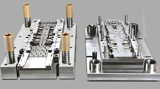
Một bộ khuôn dập gồm hai nửa bổ sung cho nhau được đặt bên trong một máy ép tạo ra lực rất lớn. Theo đặc tả kỹ thuật của ngành, những dụng cụ này thực hiện bốn chức năng thiết yếu sau:
- Định vị: Định vị chính xác vật liệu trước khi bắt đầu bất kỳ thao tác nào
- Kẹp: Cố định phôi để ngăn ngừa chuyển động trong quá trình tạo hình
- Hoạt động: Thực hiện các thao tác gia công mang lại giá trị như cắt, uốn, đục lỗ, tạo gân, tạo hình, kéo sâu, kéo giãn, dập nổi và ép chảy
- Giải phóng: Đẩy chi tiết đã hoàn thành ra ngoài để chuẩn bị cho chu kỳ tiếp theo
Hiểu rõ khuôn dập trong sản xuất giúp làm rõ vai trò của nó. Theo định nghĩa, khuôn dập là thành phần cái — tức là khoang rỗng hoặc lỗ mở tiếp nhận vật liệu và hỗ trợ định hình vật liệu đó. Khi kết hợp với chày dập (thành phần đực), ta có một hệ thống khuôn-dập hoàn chỉnh, có khả năng sản xuất mọi thứ từ các đầu nối điện tử nhỏ đến các tấm thân ô tô cỡ lớn.
Cách khuôn dập biến đổi kim loại thô
Điều gì làm nên sự khác biệt của dập kim loại so với các phương pháp gia công kim loại khác? Câu trả lời nằm ở đặc tính tạo hình nguội và hiệu quả đáng kinh ngạc của nó.
Khi đặt câu hỏi "khuôn dập được sử dụng để làm gì", hãy xem xét điều sau: một khuôn dập tiến bộ duy nhất có thể thực hiện nhiều thao tác — cắt, uốn, tạo hình — trong một chuyển động liên tục. Vật liệu được đưa vào máy ép và với mỗi hành trình, nó tiến gần hơn tới trạng thái chi tiết hoàn chỉnh. Không cần nung nóng. Không cần nấu chảy. Chỉ có sự biến đổi cơ học chính xác.
Quy trình này mang lại những ưu điểm nổi bật:
- Tốc độ sản xuất cao, phù hợp cho sản xuất hàng loạt
- Độ nhất quán về kích thước tuyệt vời trên hàng nghìn chi tiết
- Lượng phế liệu vật liệu tối thiểu so với các phương pháp gia công loại bỏ
- Mức tiêu thụ năng lượng thấp hơn so với các quy trình tạo hình nóng
Đối với các chuyên gia sản xuất đang đánh giá các phương pháp sản xuất, khái niệm khuôn dập không chỉ đơn thuần là một thuật ngữ. Đây là một điểm ra quyết định chiến lược. Khuôn dập đòi hỏi khoản đầu tư ban đầu đáng kể, nhưng lại mang lại hiệu quả kinh tế trên từng chi tiết vượt trội ở quy mô lớn—do đó, chúng trở thành nền tảng của nhiều ngành công nghiệp, từ ô tô đến điện tử tiêu dùng.
Trong các phần tiếp theo, bạn sẽ tìm hiểu chính xác cách thức vận hành của những công cụ độ chính xác cao này, các loại khuôn nào phù hợp với từng ứng dụng khác nhau và cách tối đa hóa giá trị của chúng trong suốt vòng đời hoạt động.
Các thành phần thiết yếu của bộ khuôn dập
Bạn đã bao giờ tự hỏi điều gì khiến một bộ khuôn dập có thể tạo ra cùng một chi tiết chính xác hàng nghìn lần mà không có sai lệch nào? Bí quyết nằm ở các thành phần được thiết kế kỹ lưỡng của nó—mỗi thành phần đều được thiết kế để thực hiện một chức năng cụ thể, đồng thời hoạt động ăn khớp hài hòa với các thành phần khác. Việc hiểu rõ những yếu tố này sẽ thay đổi cách bạn đánh giá, bảo trì và tối ưu hóa các quy trình dập của mình.
Một bộ khuôn dập không phải là một công cụ đơn lẻ mà thực chất là một tập hợp tinh vi gồm nhiều chi tiết phụ thuộc lẫn nhau . Theo phân tích ngành, thiết kế, vật liệu và độ nguyên vẹn của từng chi tiết khuôn dập quyết định hơn 90% hiệu suất tổng thể và tuổi thọ vận hành của toàn bộ dụng cụ. Hãy cùng phân tích chi tiết cấu tạo bên trong.
Các thành phần then chốt đảm bảo độ chính xác
Hãy hình dung một bộ khuôn dập gồm hai nhóm chi tiết: các thành phần kết cấu đảm bảo độ ổn định và độ căn chỉnh; và các thành phần làm việc trực tiếp tiếp xúc và định hình vật liệu. Cả hai nhóm đều mang tính thiết yếu—bỏ qua bất kỳ nhóm nào cũng sẽ làm giảm chất lượng chi tiết.
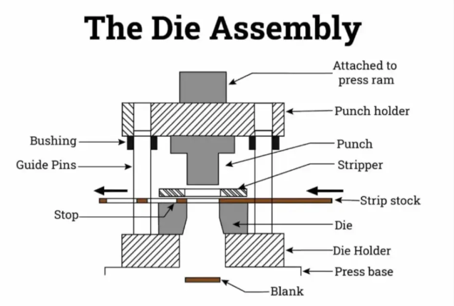
- Đế khuôn trên và đế khuôn dưới: Những tấm đế nặng này tạo thành "bộ khung" của toàn bộ bộ khuôn. Đế khuôn dưới được lắp cố định vào bàn máy ép (bàn đỡ), trong khi đế khuôn trên được gắn vào cần ép của máy. Chúng giữ tất cả các thành phần khác ở vị trí căn chỉnh chính xác và cung cấp nền tảng ổn định để chịu đựng các lực khổng lồ phát sinh trong quá trình làm việc.
- Chốt Dẫn Hướng và Bạc Dẫn Hướng: Hãy hình dung những chi tiết này như các khớp nối giúp hai nửa khuôn di chuyển luôn duy trì độ đồng tâm hoàn hảo. Các chốt đã tôi cứng, được mài chính xác trên một đế khuôn sẽ trượt vào các bạc lót cũng có độ chính xác cao tương ứng trên đế khuôn đối diện. Nếu thiếu chúng, độ đồng tâm giữa dao dập và khuôn sẽ bị lệch, dẫn đến mài mòn sớm và sai lệch kích thước.
- Tấm đệm: Được bố trí phía sau các dao dập và các nút khuôn, những tấm thép đã tôi cứng này phân bổ đều áp lực lên toàn bộ bề mặt đế khuôn. Chúng ngăn ngừa sự tập trung ứng suất cục bộ có thể làm biến dạng hoặc vỡ giá đỡ, hoặc khiến đầu dao dập bị "phình ra" (mushroom) do chịu nhiều lần va đập liên tiếp.
- Tấm dao dập (giá đỡ dao dập): Bộ phận này cố định các con đội chắc chắn tại vị trí, đảm bảo chiều cao và độ căn chỉnh nhất quán. Một con đội khuôn phải luôn duy trì vị trí hoàn toàn thẳng đứng trong hàng triệu chu kỳ — tấm đỡ con đội giúp điều này trở thành hiện thực.
- Tấm tách phôi: Sau mỗi lần đột, vật liệu có xu hướng bám vào con đội do tính đàn hồi tự nhiên của nó. Tấm tách (stripper plate) tách vật liệu này ra trong hành trình đi lên, giúp quá trình vận hành diễn ra trơn tru và ngăn ngừa tình trạng kẹt.
- Chốt dẫn hướng: Đóng vai trò then chốt trong khuôn tiến bộ, các chốt định vị (pilots) là những chốt chính xác dùng để xác định vị trí dải vật liệu bằng cách ăn khớp với các lỗ đã được đột trước đó. Chúng đảm bảo rằng mỗi trạm nhận phôi ở đúng vị trí cần thiết — yếu tố thiết yếu để duy trì dung sai chặt chẽ qua nhiều công đoạn gia công.
Hiểu về cụm khối khuôn
Các bộ phận làm việc — tức những bộ phận tiếp xúc trực tiếp với vật liệu — cần được quan tâm đặc biệt vì chúng chịu ứng suất lớn nhất và mài mòn nhiều nhất.
Các lỗ đục đóng vai thành phần nam, di chuyển xuống dưới để thực hiện các thao tác đục lỗ, cắt rời hoặc tạo hình. Hình dạng của nó xác định hình dáng của các đường cắt hoặc chi tiết được tạo ra trên phôi. nút khuôn đóng vai thành phần nữ. Lớp lót chính xác này có một khoang phù hợp với hình dạng của chày, với khe hở được tính toán cẩn thận giữa chúng.
Khe hở giữa chày và cối là yếu tố then chốt ảnh hưởng đến chất lượng chi tiết. Các tiêu chuẩn công nghiệp thường quy định khe hở tối ưu nằm trong khoảng 5–8% độ dày vật liệu. Nếu quá nhỏ, sẽ gây mài mòn quá mức và làm tăng yêu cầu lực ép của máy. Nếu quá lớn, sẽ xuất hiện ba-vơ trên các cạnh cắt.
| Thành phần | Chức năng chính | Chỉ báo mài mòn |
|---|---|---|
| Lỗ đục | Thực hiện các thao tác cắt hoặc tạo hình | Bong mảnh, làm tròn mép, trầy xước bề mặt |
| Nút khuôn | Cung cấp khoang để chày đi vào; đỡ vật liệu | Mài mòn mép, tăng đường kính, trầy xước bề mặt |
| Tấm tách phôi | Loại bỏ vật liệu bám trên chày trong quá trình chày rút về | Hình thành rãnh, mô hình mài mòn không đều |
| Chốt dẫn hướng | Duy trì độ đồng tâm giữa hai nửa cối | Trầy xước bề mặt, giảm đường kính |
| Chốt dẫn | Định vị vật liệu dải tại mỗi trạm | Mòn đầu dập, giảm đường kính |
Cách Thiết Kế Chi Tiết Điều Chỉnh Theo Độ Dày Vật Liệu
Khi làm việc với vật liệu có độ dày lớn hơn, yêu cầu đối với chi tiết thay đổi đáng kể. Vật liệu nặng hơn đòi hỏi các tấm khuôn (die shoes) chắc chắn hơn để chống cong vênh dưới tải trọng tăng cao. Các tấm đệm (backing plates) trở nên dày hơn nhằm chịu được lực va chạm lớn hơn. Hình dạng đầu dập (punch geometry) có thể cần gia cường để ngăn ngừa hiện tượng mất ổn định (buckling).
Đối với vật liệu mỏng hơn, độ chính xác càng trở nên quan trọng hơn nữa. Khe hở giữa đầu dập và khuôn (punch and die clearance) phải được thu hẹp hơn; chốt dẫn hướng và bạc dẫn hướng (guide pins and bushings) phải duy trì dung sai chặt hơn; đồng thời áp lực của tấm đẩy phôi (stripper plate pressure) cần được hiệu chuẩn cẩn thận nhằm tránh làm biến dạng các chi tiết mỏng manh.
Cũng cần xem xét cách chất lượng các bộ phận ảnh hưởng trực tiếp đến độ chính xác cuối cùng của chi tiết. Một khuôn dập có các bạc dẫn đã mòn vẫn có thể sản xuất ra chi tiết, nhưng những chi tiết này sẽ cho thấy sự sai lệch về kích thước. Một máy dập khuôn hoạt động với các chốt định vị bị hư hỏng sẽ biểu hiện tình trạng lệch tâm ngày càng tăng qua các trạm làm việc. Những suy giảm tinh vi như vậy thường không được phát hiện cho đến khi tỷ lệ phế phẩm tăng cao hoặc khách hàng phản ánh các vấn đề về chất lượng.
Các nhà sản xuất thông minh theo dõi một cách hệ thống các mô hình hao mòn của các bộ phận. Họ biết rằng cạnh đục (punch) thường cần được mài sắc lại sau mỗi 50.000–100.000 lần đục, tùy thuộc vào độ cứng của vật liệu. Họ giám sát bề mặt các chốt dẫn để phát hiện sớm nhất các dấu hiệu trầy xước do ma sát (galling). Họ thay thế lò xo đẩy phôi trước khi hiện tượng mỏi làm giảm áp lực đẩy phôi không ổn định.
Khi các bộ phận này phối hợp vận hành đúng cách, khuôn dập đạt được độ lặp lại cần thiết để sản xuất hàng loạt trở nên kinh tế. Tuy nhiên, việc lựa chọn đúng loại khuôn phù hợp với ứng dụng của bạn cũng quan trọng ngang bằng với việc hiểu rõ các thành phần bên trong của nó.
Các loại khuôn dập và thời điểm nên sử dụng từng loại
Việc lựa chọn loại khuôn dập phù hợp không chỉ là một quyết định kỹ thuật—mà còn là một quyết định chiến lược, ảnh hưởng đến chi phí sản xuất, thời gian giao hàng và chất lượng chi tiết trong nhiều năm tới. Tuy nhiên, nhiều nhà sản xuất gặp khó khăn với lựa chọn này vì phần lớn tài liệu hiện có chỉ định nghĩa các loại khuôn mà không giải thích rõ trường hợp nào nên sử dụng loại nào.
Nghe có vẻ quen thuộc? Bạn không đơn độc. Sự khác biệt giữa việc lựa chọn khuôn dập liên tục so với khuôn dập chuyển vị có thể dẫn đến khoản đầu tư vào khuôn đắt hơn hàng trăm nghìn đô la Mỹ và làm thay đổi đáng kể chi phí trên mỗi chi tiết. Hãy cùng phân tích từng loại khuôn và xây dựng một khung ra quyết định thực tiễn mà bạn thực sự có thể áp dụng.
Phù hợp hóa Loại Khuôn với Yêu Cầu Sản Xuất
Mỗi loại khuôn dập được phát triển nhằm giải quyết những thách thức sản xuất cụ thể. Việc hiểu rõ nguồn gốc và mục đích thiết kế của từng loại sẽ giúp bạn lựa chọn đúng công cụ cho nhu cầu sản xuất của mình.
Khuôn tiến bộ đại diện cho những máy dập khối lượng lớn. Quy trình dập tiến bộ đưa một dải kim loại liên tục qua nhiều trạm, mỗi trạm thực hiện một thao tác cụ thể—cắt, uốn, tạo hình—khi vật liệu di chuyển tiến về phía trước sau mỗi lần nhấn của máy dập. Chi tiết vẫn được giữ nguyên gắn với dải kim loại cho đến trạm cuối cùng, nơi nó được tách ra dưới dạng một thành phần hoàn chỉnh.
Điều gì khiến quy trình dập tiến bộ trở nên mạnh mẽ đến vậy? Đó là tốc độ và hiệu quả. Một bộ khuôn dập tiến bộ duy nhất có thể thực hiện tới chục thao tác trong khoảng thời gian mà các phương pháp khác chỉ hoàn tất được một thao tác. Đối với các chi tiết ô tô, quy trình dập tiến bộ sản xuất hàng triệu giá đỡ, kẹp và đầu nối với độ đồng nhất tuyệt vời. Khi sản lượng hàng năm của bạn vượt quá 100.000 chi tiết, bộ khuôn dập tiến bộ thường mang lại chi phí trên mỗi chi tiết thấp nhất, bất chấp khoản đầu tư ban đầu cao hơn cho khuôn.
Khuôn chuyển (Transfer) tiếp cận theo một cách khác. Trong dập khuôn chuyển vị, phôi tách rời khỏi dải kim loại ngay tại trạm đầu tiên. Các ngón tay cơ khí hoặc hệ thống tự động sau đó vận chuyển từng phôi riêng lẻ giữa các trạm, mỗi trạm chuyên thực hiện một công đoạn cụ thể. Phương pháp này đặc biệt phù hợp với các chi tiết lớn và phức tạp hơn, yêu cầu thực hiện các thao tác từ nhiều góc độ.
Tại sao nên chọn dập chuyển vị thay vì phương pháp dập liên tục? Vì tính linh hoạt. Khuôn chuyển vị xử lý được các chi tiết kéo sâu, các hình dạng phức tạp yêu cầu ren hoặc vân xoắn, cũng như các bộ phận quá lớn để có thể giữ nguyên kết nối với dải kim loại. Các giá đỡ trong ngành hàng không vũ trụ, vỏ máy móc hạng nặng và các thành phần cấu trúc ô tô thường yêu cầu sử dụng khuôn chuyển vị do kích thước và độ phức tạp của chúng.
Compound dies thực hiện nhiều thao tác—thường là cắt và tạo hình—trong một lần gõ khuôn duy nhất. Khác với khuôn tiến bộ, vốn yêu cầu nhiều lần gõ khi vật liệu di chuyển, khuôn tổ hợp hoàn tất toàn bộ công việc ngay lập tức. Điều này khiến chúng trở nên lý tưởng cho các chi tiết phẳng đòi hỏi độ chính xác cao, chẳng hạn như vòng đệm, gioăng làm kín và các lá thép kỹ thuật điện.
Điều phải đánh đổi? Gia công dập khuôn tổ hợp thường xử lý được các hình dạng đơn giản hơn so với phương pháp khuôn tiến bộ hoặc khuôn chuyển vị. Tuy nhiên, đối với sản xuất ở quy mô trung bình các chi tiết phẳng, khuôn tổ hợp mang lại chi phí chế tạo khuôn thấp hơn đồng thời vẫn đảm bảo độ chính xác kích thước tuyệt vời.
Khuôn tổ hợp kết hợp các thao tác cắt và không cắt trong một lần gõ duy nhất—ví dụ như vừa cắt phôi vừa kéo sâu đồng thời. Chúng được thiết kế đặc biệt cho các thao tác phức tạp thực hiện trong một lần gõ, trong đó nhiều bước tạo hình phải diễn ra đồng thời để đạt được hình học mong muốn.
Khung quyết định lựa chọn giữa khuôn tiến bộ và khuôn chuyển vị
Khi bạn đứng trước điểm ra quyết định, những yếu tố nào nên làm cơ sở để lựa chọn? Hãy xem xét các hướng dẫn thực tiễn sau:
- Kích thước chi tiết có vai trò quan trọng: Nếu chi tiết của bạn vượt quá khoảng 12 inch (30,5 cm) ở bất kỳ chiều nào, khuôn chuyển thường trở nên cần thiết vì cơ chế cấp băng kim loại của khuôn tiến bộ sẽ trở nên không thực tế.
- Các chi tiết kéo sâu đòi hỏi phải tách riêng: Các chi tiết yêu cầu độ sâu kéo lớn hơn đường kính của chúng thường cần sử dụng khuôn chuyển, bởi vì băng kim loại sẽ cản trở các thao tác tạo hình sâu.
- Tồn tại ngưỡng sản lượng: Dưới 50.000 đơn vị mỗi năm, khuôn tổ hợp thường là lựa chọn kinh tế nhất. Trong khoảng từ 50.000 đến 100.000 đơn vị, lựa chọn phụ thuộc vào mức độ phức tạp của chi tiết. Trên 100.000 đơn vị, khuôn tiến bộ thường chiếm ưu thế về chi phí trên mỗi chi tiết.
- Các công đoạn gia công phụ tích lũy chi phí: Khuôn chuyển có thể tích hợp các thao tác chuyên biệt như tiện ren, tạo vân xoắn và các công đoạn khác—những thao tác này nếu thực hiện bằng các loại khuôn khác sẽ đòi hỏi các quy trình riêng biệt, từ đó có thể bù đắp chi phí vận hành cao hơn của khuôn chuyển.
| Tiêu chí | Dies tiến bộ | Khuôn chuyển tiếp (Transfer Die) | Dụng cụ phức hợp |
|---|---|---|---|
| Khối lượng sản xuất | Sản lượng cao (trên 100.000 chiếc/năm) | Trung bình đến cao | Trung bình đến thấp |
| Độ Phức Tạp Của Chi Tiết | Độ phức tạp trung bình; nhiều công đoạn được thực hiện tuần tự | Độ phức tạp cao; thiết kế tinh xảo, chi tiết kéo sâu | Đơn giản đến trung bình; chủ yếu là các chi tiết phẳng |
| Kích thước chi tiết | Chi tiết nhỏ đến trung bình | Chi tiết trung bình đến lớn | Chi tiết nhỏ đến trung bình |
| Thời gian lắp đặt | Thấp; cấp liệu dải liên tục | Cao hơn; yêu cầu hiệu chuẩn cơ chế chuyển tiếp | Trung bình; thiết lập tại một trạm duy nhất |
| Chi phí khuôn mẫu | Đầu tư ban đầu cao hơn | Khoản đầu tư ban đầu cao nhất | Đầu tư ban đầu thấp hơn |
| Chi phí trên từng bộ phận | Thấp nhất ở khối lượng lớn | Trung bình; phụ thuộc vào độ phức tạp | Hiệu quả đối với các hình học đơn giản hơn |
| Ứng Dụng Điển Hình | Các giá đỡ ô tô, bộ nối điện tử, kẹp | Các bộ phận hàng không vũ trụ, bộ phận kết cấu, ống | Vòng đệm, gioăng, phôi bánh xe, lá thép kỹ thuật |
Xem xét về ngân sách và hình học chi tiết
Các ràng buộc ngân sách và hình học chi tiết của bạn thường thu hẹp lựa chọn trước khi các yếu tố về khối lượng sản xuất được xem xét.
Đối với các công ty khởi nghiệp hoặc các đợt sản xuất có khối lượng thấp, khuôn dập tổ hợp mang lại điểm bắt đầu dễ tiếp cận nhất. Cấu tạo đơn giản hơn của chúng dẫn đến chi phí chế tạo khuôn thấp hơn và thời gian giao hàng nhanh hơn. Nếu các chi tiết của bạn tương đối phẳng và không yêu cầu nhiều thao tác tạo hình tuần tự, khuôn dập tổ hợp sẽ đảm bảo độ chính xác mà không cần đầu tư quá lớn.
Các hình dạng phức tạp sẽ thúc đẩy bạn chuyển sang sử dụng khuôn dập chuyển vị, bất kể khối lượng sản xuất là bao nhiêu. Khi thiết kế của bạn bao gồm các gân tăng cứng, các mặt bích (boss), ren hoặc các dạng đa hướng, phương pháp dập chuyển vị cung cấp tính linh hoạt để định hướng phôi một cách tối ưu tại mỗi trạm. Khả năng này thường loại bỏ các công đoạn gia công phụ tốn kém.
Các nhà sản xuất quy mô lớn sản xuất linh kiện ô tô thông qua phương pháp dập liên tục đạt được chi phí trên mỗi chi tiết thấp đến mức không thể đạt được bằng các phương pháp khác. Chi phí đầu tư ban đầu cho khuôn dập được phân bổ trên hàng triệu chu kỳ, trong khi quá trình cấp liệu liên tục tối đa hóa hiệu suất sử dụng máy dập. Đối với các cụm giá đỡ, đầu nối đầu cuối và các linh kiện tương tự, khuôn dập liên tục vẫn là tiêu chuẩn ngành.
Hiểu rõ những sự đánh đổi này giúp bạn có những cuộc trao đổi có cơ sở với các nhà cung cấp khuôn dập và đưa ra quyết định phù hợp với chiến lược sản xuất của mình. Tuy nhiên, việc lựa chọn loại khuôn phù hợp chỉ là bước khởi đầu — bản thân quá trình dập đòi hỏi các chuỗi thao tác chính xác để biến vật liệu phôi phẳng thành các chi tiết hoàn chỉnh.
Quy Trình Dập Được Giải Thích Từng Bước
Bạn đã chọn loại khuôn dập của mình và hiểu rõ các thành phần cấu tạo nên nó—nhưng thực tế điều gì xảy ra khi máy dập thực hiện một chu kỳ? Quá trình dập kim loại biến tấm kim loại phẳng thành các chi tiết chức năng thông qua một chuỗi hành động cơ học chính xác, và việc hiểu rõ chuỗi thao tác này giúp bạn chẩn đoán sự cố, tối ưu hóa sản xuất cũng như giao tiếp hiệu quả với các đối tác sản xuất.
Quy trình sản xuất dập kim loại có vẻ đơn giản từ bên ngoài: kim loại đưa vào, chi tiết được đưa ra. Nhưng bên trong máy dập, những hiện tượng phức tạp liên quan đến hành vi của vật liệu diễn ra trong một phần nhỏ giây. Hãy cùng xem xét chi tiết những gì xảy ra, bắt đầu từ thời điểm vật liệu được đưa vào cho đến khi chi tiết hoàn chỉnh được đẩy ra.
Từ Tấm Kim Loại Đến Chi Tiết Hoàn Thành
Mỗi chu kỳ dập đều tuân theo cùng một trình tự cơ bản, bất kể bạn đang vận hành khuôn cắt phôi đơn giản hay khuôn tiến bộ phức tạp. Dưới đây là toàn bộ quy trình dập kim loại được chia thành các giai đoạn thiết yếu:
- Cấp liệu và định vị vật liệu: Quy trình dập tấm kim loại bắt đầu khi cuộn vật liệu hoặc các phôi đã cắt sẵn được đưa vào máy ép. Các bộ cấp liệu tự động đẩy vật liệu tiến về phía trước một khoảng cách chính xác (gọi là bước tiến) giữa mỗi lần hành trình. Các chốt định vị lọt vào các lỗ đã được khoan trước đó để định vị dải vật liệu ở vị trí mục tiêu với độ chính xác đến phần nghìn inch.
- Bắt đầu đóng khuôn: Con trượt của máy ép bắt đầu di chuyển xuống dưới, đưa cụm khuôn trên tiến lại gần khuôn dưới. Các chốt dẫn hướng lọt vào các bạc dẫn hướng tương ứng, đảm bảo sự căn chỉnh hoàn hảo giữa hai nửa khuôn trước khi bất kỳ tiếp xúc tạo hình nào xảy ra.
- Tiếp xúc và kẹp vật liệu: Tấm gạt hoặc đệm ép tiếp xúc với vật liệu trước tiên, kẹp chặt vật liệu lên bề mặt khuôn. Việc này ngăn chặn sự dịch chuyển của vật liệu trong quá trình tạo hình và kiểm soát dòng chảy vật liệu trong các thao tác kéo sâu.
- Các công đoạn tạo hình: Khi vật liệu đã được cố định chắc chắn, các chày và các phần tạo hình sẽ tác động lên phôi. Tùy theo thiết kế khuôn, các thao tác như cắt, uốn, kéo sâu hoặc các thao tác khác sẽ diễn ra đồng thời hoặc theo trình tự nhanh chóng.
- Điểm chết dưới: Con trượt đạt đến điểm thấp nhất—điểm chết dưới—nơi lực tạo hình cực đại được áp dụng. Thời điểm này quyết định kích thước cuối cùng của chi tiết và chất lượng độ bóng bề mặt.
- Lùi con trượt: Khi con trượt đi lên, tấm đẩy giữ vật liệu ở vị trí cố định, ngăn vật liệu bị nâng lên cùng các chày. Các lò xo cung cấp lực đẩy cần thiết để tách chi tiết đã tạo hình ra khỏi bề mặt khuôn.
- Đẩy chi tiết ra: Các chi tiết hoàn thành hoặc rơi xuống qua các lỗ khuôn vào thùng thu gom, hoặc vẫn còn nằm trên dải vật liệu cho đến khi được cắt rời hoàn toàn. Trong các quá trình chuyển tiếp, các ngón gắp cơ khí sẽ nắm lấy chi tiết và di chuyển chúng tới các trạm tiếp theo.
- Đặt lại chu kỳ: Bộ cấp liệu đưa vật liệu mới vào, và chu trình được lặp lại—thường đạt hàng trăm lần mỗi phút trong các ứng dụng tốc độ cao.
Hiểu chi tiết về các thao tác tạo hình
Quá trình dập kim loại bao gồm nhiều thao tác tạo hình riêng biệt, mỗi thao tác tạo ra những thay đổi hình học cụ thể trên phôi. Việc hiểu rõ cách thức hoạt động của từng thao tác giúp bạn thiết kế chi tiết tốt hơn và xử lý hiệu quả các vấn đề liên quan đến chất lượng.
Cong làm biến dạng kim loại xung quanh một trục thẳng. Vật liệu ở mặt trong của chỗ uốn bị nén, trong khi mặt ngoài bị giãn ra. Theo nghiên cứu về gia công kim loại , một tiết diện phẳng vuông góc với tấm vẫn giữ nguyên là phẳng trong quá trình uốn, với biến dạng thay đổi tuyến tính từ trạng thái nén tại bề mặt trong đến trạng thái kéo tại bề mặt ngoài. Trục trung hòa—nơi biến dạng bằng không—dịch chuyển nhẹ về phía mặt trong của chỗ uốn.
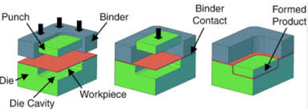
Vẽ biến các phôi phẳng thành các chi tiết có dạng cốc hoặc dạng hộp. Khi chày đẩy vật liệu vào lòng khuôn, mép ngoài của phôi bị kéo vào trong. Điều này tạo ra ứng suất nén tại phần vành (flange), có thể gây nhăn nếu không được kiểm soát đúng cách bằng lực ép của bộ kẹp phôi. Quá trình dập tiến bộ thường tích hợp các trạm kéo cho các chi tiết yêu cầu độ sâu.
Uốn mép uốn cong mép của một chi tiết để tạo thành viền vuông góc với bề mặt chính. Uốn giãn kéo vật liệu ra ngoài, tạo ra lực căng. Uốn co đẩy vật liệu vào trong, tạo ra lực nén có thể gây ra hiện tượng nhăn (buckling) nếu thiết kế khuôn không phù hợp.
Sơn mộc tạo ra các hoa văn nổi hoặc chìm trên tấm kim loại mà không làm thay đổi đáng kể độ dày vật liệu. Chày và cối phối hợp với nhau để dịch chuyển cục bộ vật liệu, tạo ra các biểu tượng, gân gia cường hoặc họa tiết trang trí.
Đúc áp dụng áp lực cực cao để tái tạo chi tiết bề mặt tinh xảo. Quá trình dập ép (coining)—được đặt tên theo ứng dụng trong việc đúc tiền—đạt được độ chính xác kích thước vượt trội bằng cách ép vật liệu chảy đầy vào từng chi tiết nhỏ nhất của khoang khuôn. Khác với các nguyên công khác, quá trình dập ép gây ra sự giảm độ dày đo được tại vùng được dập ép.
Quy trình dập nhôm đòi hỏi sự chú ý đặc biệt đối với các nguyên công này vì nhôm bị biến cứng do gia công nhanh hơn thép, ảnh hưởng đến hiện tượng đàn hồi ngược (springback) và giới hạn khả năng tạo hình.
Hành vi Vật liệu Trong Quá trình Tạo hình Lạnh
Khi bạn hiểu được những gì xảy ra với kim loại ở cấp độ vi cấu trúc, bạn có thể dự đoán và ngăn ngừa nhiều khuyết tật phổ biến.
Cứng hóa do biến dạng xảy ra khi biến dạng dẻo làm sắp xếp lại cấu trúc tinh thể của kim loại. Mật độ lệch tăng lên, khiến vật liệu trở nên cứng hơn và ít dẻo hơn theo thời gian. Đây là lý do vì sao các chi tiết được tạo hình mạnh thường yêu cầu ủ trung gian—xử lý nhiệt nhằm khôi phục tính dẻo bằng cách cho phép quá trình kết tinh lại diễn ra. Gia công lạnh có thể làm tăng giới hạn chảy lên 50% hoặc hơn, điều này ảnh hưởng đến các công đoạn tạo hình tiếp theo cũng như đặc tính cuối cùng của chi tiết.
Hiệu ứng hồi phục xảy ra vì không phải toàn bộ biến dạng đều là vĩnh viễn. Phần biến dạng đàn hồi sẽ phục hồi khi các lực tạo hình được giải phóng, khiến các chi tiết bị uốn "đàn hồi" một phần trở lại hình dạng ban đầu. Theo nghiên cứu về cơ học tạo hình, hiện tượng đàn hồi sau uốn (springback) xuất phát từ sự thay đổi của ứng suất uốn dọc theo chiều dày—vật liệu gần trục trung hòa vẫn ở dưới giới hạn chảy và có xu hướng quay trở lại cấu hình ban đầu.
Để bù trừ hiện tượng đàn hồi sau uốn, cần thực hiện việc uốn quá mức (thiết kế khuôn có bán kính nhỏ hơn bán kính yêu cầu của chi tiết thành phẩm) hoặc ép tới đáy (áp dụng thêm lực tại điểm chết dưới cùng nhằm biến dạng dẻo vùng vật liệu có tính đàn hồi). Mức độ đàn hồi sau uốn phụ thuộc vào đặc tính vật liệu, bán kính uốn và chiều dày—các vật liệu có độ bền cao hơn sẽ thể hiện hiện tượng đàn hồi sau uốn lớn hơn.
Thay đổi cấu trúc hạt đi kèm với mọi quá trình tạo hình nguội. Các hạt kim loại bị kéo dài theo hướng dòng vật liệu, tạo ra các tính chất có hướng gọi là hiện tượng dị hướng. Điều này ảnh hưởng đến giới hạn tạo hình ở các hướng khác nhau và có thể gây ra hiện tượng "tai"—chiều cao không đều ở các cốc được dập sâu do sự thay đổi tính chất vật liệu dọc theo chu vi.
Các Thông Số Máy Ép Ảnh Hưởng Như Thế Nào Đến Chất Lượng Chi Tiết
Ba thông số chính của máy ép trực tiếp ảnh hưởng đến chi tiết thành phẩm của bạn: lực ép (tấn), tốc độ hành trình và khe hở khuôn. Việc thiết lập chính xác các thông số này là yếu tố phân biệt giữa những chi tiết đạt yêu cầu và những chi tiết vượt trội.
Lực ép phải vượt quá lực cần thiết cho các thao tác cụ thể của bạn. Lực ép không đủ sẽ dẫn đến tạo hình không hoàn chỉnh, mài mòn quá mức và có thể gây hư hại máy ép. Lực ép quá lớn sẽ làm lãng phí năng lượng và có thể gây hiện tượng dập quá mức hoặc làm hỏng các chi tiết tinh xảo. Hãy tính toán lực ép yêu cầu dựa trên độ bền vật liệu, độ dày và chu vi của các cạnh được cắt hoặc tạo hình.
Tốc độ hành trình ảnh hưởng đến cả năng suất và chất lượng. Tốc độ cao hơn làm tăng sản lượng nhưng đồng thời cũng làm tăng lực va chạm và sinh nhiệt. Một số vật liệu—đặc biệt là thép không gỉ có hiện tượng biến cứng khi gia công nhanh—lại đạt hiệu quả tốt hơn khi gia công ở tốc độ chậm hơn. Việc tích tụ nhiệt ở tốc độ cao có thể ảnh hưởng đến hiệu suất bôi trơn và gây hiện tượng dính mài mòn (galling) giữa bề mặt dụng cụ và phôi.
Khe hở cối —khe hở giữa chày và cối—xác định trực tiếp chất lượng mép cắt trong các nguyên công cắt. Các tiêu chuẩn công nghiệp thường quy định khe hở tối ưu ở mức 5–8% chiều dày vật liệu. Khe hở nhỏ hơn tạo ra mép cắt sạch hơn nhưng đòi hỏi lực lớn hơn và làm tăng tốc độ mài mòn dụng cụ. Khe hở lớn hơn làm giảm yêu cầu về tuổi thọ dụng cụ nhưng lại gây ra ba via và mép cắt thô ráp hơn.
Các thông số này tương tác với nhau theo những cách phức tạp. Một bộ khuôn chạy ở độ hở phù hợp, với lực ép đầy đủ và tốc độ thích hợp sẽ tạo ra các chi tiết có mép sạch, kích thước chính xác và chất lượng đồng đều. Sự sai lệch ở bất kỳ thông số nào cũng sẽ lan truyền sang các thông số khác, biểu hiện dưới dạng ba-vơ, sai lệch kích thước hoặc khuyết tật bề mặt.
Làm chủ quy trình dập đòi hỏi phải hiểu rõ những mối quan hệ này—nhưng không kém phần quan trọng là lựa chọn đúng vật liệu làm khuôn để chịu được các điều kiện khắc nghiệt bên trong máy dập.
Lựa chọn vật liệu khuôn và đặc tả kỹ thuật kỹ sư
Thiết kế khuôn dập của bạn có thể hoàn hảo, nhưng nếu bạn chọn sai vật liệu, bạn đang tự đặt mình vào tình trạng mài mòn sớm, hư hỏng bất ngờ và gián đoạn sản xuất tốn kém. Việc lựa chọn vật liệu khuôn nằm trong số những quyết định quan trọng nhất trong kỹ thuật chế tạo dụng cụ—thế nhưng nó thường bị xem nhẹ như một việc làm sau cùng.
Tại sao việc lựa chọn vật liệu lại quan trọng đến vậy? Hãy xem xét điều này: các khuôn dập kim loại phải chịu đựng lực cơ học cực lớn trong mỗi lần hành trình ép. Chúng phải duy trì độ chính xác về kích thước trong hàng triệu chu kỳ đồng thời chống mài mòn do các tấm kim loại có tính mài mòn cao. Vật liệu không phù hợp sẽ nhanh chóng hư hỏng. Ngược lại, vật liệu phù hợp sẽ đảm bảo quá trình sản xuất ổn định và đáng tin cậy trong nhiều năm. Cùng tìm hiểu cách đưa ra quyết định then chốt này.
Lựa chọn vật liệu khuôn phù hợp cho ứng dụng của bạn
Khi kỹ sư xác định vật liệu làm khuôn dập thép, họ phải cân nhắc giữa những yêu cầu đối lập nhau. Bạn cần độ cứng để chống mài mòn, nhưng độ cứng quá cao khiến dụng cụ trở nên giòn và dễ bị vỡ mẻ. Bạn cần độ dai để hấp thụ lực va đập, nhưng vật liệu quá mềm lại bị mài mòn quá nhanh. Việc tìm ra sự cân bằng tối ưu phụ thuộc vào ứng dụng cụ thể của bạn.
Ba yếu tố chi phối việc lựa chọn vật liệu cho khuôn dập tấm kim loại:
- Vật liệu gia công: Các loại tấm kim loại cứng hơn như thép không gỉ hoặc thép hợp kim thấp cường độ cao đòi hỏi vật liệu khuôn cứng hơn so với các loại tấm nhôm hoặc thép cacbon thấp mềm hơn.
- Khối lượng sản xuất: Các lô sản xuất với khối lượng lớn làm cho việc sử dụng vật liệu khuôn cao cấp có khả năng chống mài mòn vượt trội trở nên hợp lý, trong khi các lô sản xuất nhỏ hơn có thể không bù đắp được chi phí ban đầu cao hơn.
- Dung sai yêu cầu: Các yêu cầu về dung sai kích thước chặt chẽ hơn đòi hỏi vật liệu phải duy trì hình dạng học của chúng lâu hơn dưới tác động lặp đi lặp lại của ứng suất.
Các khuôn dập kim loại tấm dùng trong ứng dụng dập ô tô phải đối mặt với điều kiện đặc biệt khắc nghiệt. Chúng phải sản xuất hàng triệu chi tiết trong khi vẫn đảm bảo độ chính xác theo dung sai được đo bằng phần nghìn inch. Đây là lý do vì sao các khuôn dập ô tô thường yêu cầu sử dụng các mác thép công cụ cao cấp với quá trình tôi luyện được kiểm soát cẩn thận.
Các cấp thép dụng cụ và đặc tính hiệu suất của chúng
Thép công cụ tạo thành nền tảng cho các khuôn công cụ hiện đại. Theo phân tích toàn diện của Ryerson, thép công cụ thường chứa từ 0,5% đến 1,5% carbon, cùng với các cacbua được hình thành bởi vonfram, crôm, vanadi và molypden. Các nguyên tố hợp kim này tạo ra độ cứng, khả năng chống mài mòn và khả năng chống biến dạng mà các ứng dụng dập yêu cầu.
Ba mác thép chiếm ưu thế trong các ứng dụng khuôn dập kim loại tấm:
Thép Dụng cụ D2 đại diện cho loại thép chịu mài mòn cao trong các ứng dụng đòi hỏi độ bền cơ học lớn. Loại thép cacbon cao, crôm cao này đạt độ cứng 62–64 HRC sau khi tôi nhiệt đúng cách. Hàm lượng crôm đáng kể tạo thành các hạt cacbua cứng, mang lại khả năng chống mài mòn xuất sắc. Thép D2 đặc biệt phù hợp cho các khuôn công cụ sử dụng lâu dài, bao gồm khuôn cắt rời (blanking), khuôn đục lỗ (punching) và khuôn uốn (forming), yêu cầu độ chính xác cao.
Thép công cụ A2 cung cấp sự cân bằng tuyệt vời giữa độ dai và khả năng chống mài mòn. Hàm lượng crôm 5% giúp đạt độ cứng cao sau quá trình tôi bằng không khí—thường ở mức 63–65 HRC. Vì thép A2 tôi trong không khí thay vì phải tôi trong dầu hoặc nước, nên nó duy trì độ ổn định kích thước rất tốt trong suốt quá trình nhiệt luyện. Điều này khiến thép A2 trở thành lựa chọn lý tưởng cho các chày cắt rời và uốn, khuôn cắt phôi (die trimming) cũng như khuôn ép phun (injection molding dies).
Thép công cụ S7 thuộc họ thép chống va đập, mang lại khả năng chịu va đập xuất sắc mà các mác thép khác không thể sánh kịp. Trong khi S7 đạt độ cứng 60–62 HRC, lợi thế chính của nó nằm ở độ dai — khả năng hấp thụ chấn động cơ học mà không bị nứt. Đối với các ứng dụng chịu lực va đập lớn như đục, dập và bộ dụng cụ tán đinh, S7 vượt trội hơn các lựa chọn khác cứng hơn nhưng giòn hơn.
| Chất liệu | Cứng (HRC) | Chống mài mòn | Độ bền | Chi phí tương đối | Ứng dụng tốt nhất |
|---|---|---|---|---|---|
| Thép Dụng cụ D2 | 62-64 | Xuất sắc | Trung bình | Trung bình | Khuôn cắt phôi, khuôn đột lỗ, dụng cụ gia công chu kỳ dài |
| Thép công cụ A2 | 63-65 | Rất tốt | Tốt | Trung bình | Chày tạo hình, cắt biên khuôn, dụng cụ chính xác |
| Thép công cụ S7 | 60-62 | Trung bình | Xuất sắc | Trung bình | Ứng dụng chịu va đập, đục, chày dập nặng |
| Chấu hợp kim cứng | 75-80 | Đứng trên | Thấp | Cao | Sản xuất khối lượng lớn, vật liệu mài mòn |
| Thép tốc độ cao M2 | 62-64 | Xuất sắc | Tốt | Cao | Ứng dụng nhiệt độ cao, dụng cụ cắt |
Mũi khoan hợp kim cứng và vật liệu chuyên dụng
Khi các loại thép dụng cụ tiêu chuẩn không đáp ứng được tuổi thọ chống mài mòn yêu cầu, các mũi khoan hợp kim cứng cung cấp giải pháp cao cấp thay thế. Carbide vonfram đạt độ cứng 75–80 HRC — cao đáng kể so với mọi loại thép dụng cụ. Độ cứng cực cao này chuyển hóa thành khả năng chống mài mòn được đo bằng hàng triệu chu kỳ thay vì chỉ vài trăm nghìn chu kỳ.
Tuy nhiên, độ cứng của cacbua đi kèm với một sự đánh đổi: độ dai giảm. Các lưỡi cắt bằng cacbua có thể bị mẻ hoặc nứt dưới tải va đập mà thép dụng cụ có thể hấp thụ. Vì lý do này, cacbua thường được sử dụng dưới dạng các mảnh chèn (insert) bên trong thân khuôn làm bằng thép dụng cụ, thay vì được chế tạo thành các bộ phận khuôn hoàn chỉnh. Cấu trúc thép giúp hấp thụ chấn động, trong khi các cạnh cắt bằng cacbua chống mài mòn.
Đối với các ứng dụng khuôn dập kim loại tấm nhằm gia công các vật liệu mài mòn như thép mạ kẽm hoặc thép không gỉ, các đầu dập phủ cacbua thường mang lại hiệu quả kinh tế tốt nhất dù chi phí ban đầu cao hơn. Tuổi thọ kéo dài giữa các chu kỳ mài sắc giúp giảm thời gian ngừng máy và lao động bảo trì.
Yêu cầu về tôi luyện và ảnh hưởng đến hiệu năng
Thép dụng cụ thô tương đối mềm—thường vào khoảng 20 HRC. Để đạt được độ cứng làm việc cần thiết, quá trình tôi luyện phải được kiểm soát cẩn thận nhằm biến đổi cấu trúc vi mô của thép.
Theo đặc tả ngành, thép D2 yêu cầu tôi luyện ở nhiệt độ từ 1800°F đến 1875°F, sau đó tôi lại ở nhiệt độ từ 900°F đến 960°F. Thép A2 được làm nguội trong không khí từ nhiệt độ tôi luyện và tôi lại ở nhiệt độ từ 350°F đến 400°F. Thép S7 được tôi luyện ở nhiệt độ từ 1725°F đến 1850°F, với nhiệt độ tôi lại phụ thuộc vào việc ứng dụng là gia công nguội (khoảng 400°F) hay gia công nóng (lên tới 1000°F).
Xử lý nhiệt không đúng cách sẽ làm giảm hiệu quả ngay cả khi đã chọn vật liệu tốt nhất. Việc tôi luyện không đủ sẽ khiến các khuôn quá mềm, làm tăng tốc độ mài mòn. Tôi lại quá mức sẽ làm giảm độ cứng xuống dưới mức tối ưu. Việc đun nóng không đều tạo ra ứng suất nội tại gây nứt khuôn trong quá trình vận hành. Đây là lý do vì sao các nhà sản xuất khuôn uy tín luôn duy trì kiểm soát quy trình nghiêm ngặt đối với các thao tác xử lý nhiệt.
Các phương pháp xử lý bề mặt và lớp phủ giúp kéo dài tuổi thọ khuôn
Ngoài việc lựa chọn vật liệu nền, các phương pháp xử lý bề mặt và lớp phủ đóng vai trò quan trọng trong việc kéo dài tuổi thọ của khuôn dập. Theo nghiên cứu ngành về dập chính xác, các lớp phủ giúp duy trì độ nguyên vẹn của khuôn dập bằng cách giảm thiểu hiện tượng dính, bám và mài mòn—từ đó làm giảm thời gian ngừng máy, thời gian thay khuôn và chi phí bảo trì.
Ba công nghệ phủ chiếm ưu thế trong các ứng dụng dập:
- Titan Nitride (TiN): Cung cấp độ cứng và khả năng chống mài mòn xuất sắc. Màu vàng đặc trưng giúp dễ dàng nhận diện các vùng mài mòn trong quá trình kiểm tra.
- Titanium Carbonitride (TiCN): Cải thiện khả năng bôi trơn so với TiN, do đó đặc biệt phù hợp cho việc dập các vật liệu mài mòn.
- Carbon giống Kim cương (DLC): Đạt hiệu suất vượt trội trong dập tốc độ cao và các ứng dụng khô. Lớp phủ DLC làm giảm ma sát và tăng độ cứng bề mặt, từ đó kéo dài đáng kể tuổi thọ dụng cụ.
Các dụng cụ phủ lớp duy trì độ chính xác kích thước chặt chẽ hơn trong thời gian dài hơn vì ma sát giảm dẫn đến ít sinh nhiệt và giãn nở nhiệt ít hơn. Đối với sản xuất hàng loạt khuôn dập ô tô, lớp phủ thường tự hoàn vốn chỉ trong vài trăm nghìn chu kỳ đầu tiên nhờ giảm tần suất mài sắc và cải thiện độ đồng nhất của chi tiết.
Sự tương tác giữa vật liệu nền, xử lý nhiệt và lớp phủ bề mặt tạo nên toàn bộ hồ sơ hiệu năng của khuôn bạn. Việc hiểu rõ các mối quan hệ này giúp bạn lựa chọn dụng cụ phù hợp để đạt được kết quả đáng tin cậy—tuy nhiên, ngay cả những vật liệu tốt nhất cũng đòi hỏi phải kiểm định thiết kế đầy đủ trước khi triển khai chế tạo dụng cụ thực tế.
Phần mềm Thiết kế Khuôn Hiện đại và Mô phỏng CAE
Bạn đã chọn thép công cụ cao cấp và xác định chế độ nhiệt luyện tối ưu—nhưng làm thế nào để bạn biết thiết kế khuôn dập của mình thực sự khả thi trước khi chi hàng trăm nghìn đô la cho việc chế tạo khuôn vật lý? Hai thập kỷ trước, câu trả lời là phải chế tạo mẫu thử, tiến hành chạy thử và lặp lại nhiều lần với những điều chỉnh tốn kém. Ngày nay, các nhà sản xuất tiên tiến tận dụng kỹ thuật số hóa trong thiết kế để kiểm chứng thiết kế một cách ảo, phát hiện vấn đề trước khi chúng trở thành những sự cố sản xuất tốn kém.
Thiết kế khuôn dập hiện đại đã chuyển mình từ một nghề thủ công dựa trên kinh nghiệm sang một ngành kỹ thuật chính xác được hỗ trợ bởi các công cụ mô phỏng tinh vi. Việc hiểu rõ những khả năng này giúp bạn đánh giá các đối tác gia công khuôn tiềm năng và đảm bảo các dự án của bạn được hưởng lợi từ những thực tiễn tốt nhất hiện đại trong thiết kế khuôn dập kim loại.
Kỹ thuật số hóa trong Thiết kế Khuôn Hiện Đại
Việc sản xuất khuôn hiện đại bắt đầu không phải trên sàn nhà máy mà trong không gian kỹ thuật số. Các kỹ sư tạo ra các mô hình 3D chi tiết cho từng thành phần của khuôn, lắp ráp chúng một cách ảo để kiểm tra độ khít, khoảng hở và quỹ đạo chuyển động trước khi bất kỳ vật liệu kim loại nào được gia công.
Sự tích hợp CAD/CAM này mang lại nhiều lợi thế so với các phương pháp truyền thống:
- Khả năng hiển thị toàn diện: Các kỹ sư có thể xoay, cắt mặt cắt và kiểm tra khuôn từ mọi góc độ, phát hiện các vấn đề va chạm mà bản vẽ 2D không thể hiện được
- Thiết kế tham số: Việc thay đổi một kích thước sẽ tự động cập nhật các đặc tính liên quan, cho phép thực hiện nhanh chóng nhiều lần lặp lại thiết kế mà không cần tính toán lại thủ công
- Đầu ra gia công trực tiếp: Các mô-đun CAM tạo ra đường chạy dao trực tiếp từ mô hình 3D, loại bỏ các lỗi dịch chuyển giữa thiết kế và dụng cụ chế tạo
- Tạo bản sao kỹ thuật số (digital twin): Mô hình kỹ thuật số đầy đủ này phục vụ như một tài liệu tham chiếu trong suốt vòng đời của khuôn, hỗ trợ bảo trì, cải tiến và sản xuất các bộ phận thay thế
Tuy nhiên, mô hình hóa hình học chỉ kể một phần câu chuyện. Bước đột phá thực sự trong phát triển khuôn dập ô tô đến từ mô phỏng dựa trên cơ sở vật lý, cho phép dự đoán cách tấm kim loại thực tế phản ứng trong quá trình tạo hình.
Các công cụ mô phỏng giúp ngăn ngừa những sai sót tốn kém
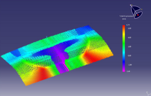
Hãy tưởng tượng bạn có thể kiểm tra thiết kế khuôn của mình hàng ngàn lần trước khi chế tạo bất kỳ thành phần vật lý nào. Đó chính xác là điều Phân tích Phần tử Hữu hạn (FEA) mang lại. Theo phân tích kỹ thuật từ ETA , FEA hoạt động bằng cách chia cấu trúc toàn bộ thành một lưới gồm nhiều phần tử nhỏ hơn và đơn giản hơn. Các phương trình toán học sau đó phân tích hành vi của từng phần tử cũng như cách nó tương tác với các phần tử lân cận, từ đó dự đoán phản ứng tổng thể dưới tải tạo hình.
Đối với thiết kế khuôn dập, mô phỏng Kỹ thuật Hỗ trợ Máy tính (CAE) giải quyết những thách thức vốn historically gây ra các sự cố tốn kém nhất:
Dự đoán nhăn: Khi ứng suất nén tại mép phôi vượt quá ngưỡng tới hạn, vật liệu bị cong vênh thành các nếp nhăn. Mô phỏng xác định những vùng này trước lần thử nghiệm đầu tiên, cho phép kỹ sư điều chỉnh áp lực của bộ kẹp phôi, bán kính khuôn hoặc hình dạng gờ kéo trong mô hình số.
Phân tích rách: Ứng suất kéo quá mức khiến vật liệu bị mỏng đi quá nhiều và cuối cùng bị rách. Nghiên cứu từ bộ phận CAE của Keysight ghi nhận rằng thiết kế chi tiết và quy trình có thể ảnh hưởng đáng kể đến chất lượng thẩm mỹ, với các khuyết tật đôi khi chỉ xuất hiện trong lần thử nghiệm đầu tiên—khi đó việc khắc phục sẽ tốn nhiều thời gian và chi phí. Mô phỏng lập bản đồ phân bố ứng suất trên toàn bộ chi tiết, làm nổi bật các vùng tiềm ẩn nguy cơ hỏng hóc để điều chỉnh thiết kế.
Bù trừ độ đàn hồi trở lại Có lẽ ứng dụng mô phỏng có giá trị nhất là dự đoán độ phục hồi đàn hồi. Thép cường độ cao tiên tiến (AHSS) và hợp kim nhôm thường thể hiện mức độ đàn hồi lớn, khiến việc đảm bảo độ chính xác về kích thước trở thành một thách thức liên tục. Mô phỏng định lượng mức độ đàn hồi dự kiến, từ đó giúp kỹ sư thiết kế hình dạng khuôn bù trừ để tạo ra các chi tiết đạt độ chính xác về kích thước sau khi phục hồi đàn hồi.
Tối ưu hóa dòng chảy vật liệu: Mô phỏng theo dõi cách vật liệu di chuyển trong quá trình tạo hình, xác định các vùng bị mỏng quá mức, dày quá mức hoặc có hướng chảy hạt không mong muốn. Thông tin này hỗ trợ đưa ra quyết định về hình dạng phôi, vùng bôi trơn và vị trí đặt gờ kéo.
| Khả năng Mô phỏng | Vấn đề được ngăn chặn | Điểm phát hiện truyền thống | Điểm phát hiện bằng mô phỏng |
|---|---|---|---|
| Phân tích khả năng tạo hình | Hiện tượng rách và mỏng quá mức | Lần thử khuôn đầu tiên | Trước khi hoàn tất thiết kế khuôn |
| Dự đoán hiện tượng nhăn | Các khuyết tật bề mặt trên các tấm hiển thị rõ | Thử nghiệm sản xuất | Trong quá trình tối ưu hóa bộ kẹp phôi |
| Bù trừ độ đàn hồi | Không phù hợp về kích thước | Kiểm tra Mẫu Đầu Tiên | Trong quá trình phát triển bề mặt khuôn |
| Tối ưu hóa phôi | Chất thải vật liệu | Phân tích Chi phí Sản xuất | Trong quá trình lập kế hoạch quy trình |
Giảm số lần lặp lại chế tạo mẫu và đẩy nhanh tiến độ sản xuất
Tác động kinh tế của mô phỏng mở rộng xa hơn nhiều so với việc ngăn ngừa khuyết tật. Việc chế tạo khuôn công cụ truyền thống thường yêu cầu ba đến năm lần thử nghiệm thực tế trước khi đạt được chất lượng chi tiết ở mức chấp nhận được. Mỗi lần thử nghiệm tiêu tốn hàng tuần thời gian và hàng chục nghìn đô la Mỹ cho gia công cơ khí, xử lý nhiệt và thời gian chạy máy ép.
Các lần thử nghiệm khuôn ảo làm rút ngắn đáng kể chu kỳ này. Các kỹ sư có thể thực hiện hàng chục lần mô phỏng trong vài ngày thay vì vài tháng, từ đó khảo sát các phương án thiết kế mà nếu thử nghiệm thực tế sẽ tốn kém đến mức không thể chấp nhận được. Khi khuôn thực tế đầu tiên được lắp lên máy ép, nó đã được tối ưu hóa—thường đạt được chi tiết đạt yêu cầu chỉ trong một hoặc hai lần thử nghiệm thay vì năm lần.
Theo phân tích ngành, phân tích phần tử hữu hạn (FEA) cho phép các nhà thiết kế kiểm tra và phân tích ảo nhiều phương án thiết kế trước khi chế tạo mẫu vật lý, từ đó giảm đáng kể thời gian và chi phí phát triển. Khả năng này đặc biệt có giá trị đối với các ứng dụng khuôn dập ô tô phức tạp, nơi chi phí chế tạo khuôn có thể vượt quá 500.000 USD.
Thiết kế nhằm thuận tiện cho sản xuất trong các quy trình dập
Các công cụ mô phỏng cũng áp dụng các nguyên tắc thiết kế nhằm thuận tiện cho sản xuất (DFM) đặc thù cho quy trình dập. Máy dập phải có khả năng sản xuất các chi tiết một cách ổn định trong hàng triệu chu kỳ — chứ không chỉ một lần duy nhất trong điều kiện lý tưởng.
Các yếu tố DFM then chốt mà mô phỏng giúp xác thực bao gồm:
- Dòng chảy vật liệu đồng đều: Đảm bảo vật liệu được kéo đều theo mọi hướng sẽ ngăn ngừa hiện tượng mỏng cục bộ và kéo dài tuổi thọ khuôn
- Bán kính góc khuôn phù hợp: Các góc quá sắc gây tập trung ứng suất, làm tăng tốc độ mài mòn và thúc đẩy nứt gãy
- Khe hở thích hợp: Mô phỏng xác nhận rằng các khoảng hở được thiết kế tạo ra chất lượng mép chấp nhận được mà không hình thành ba-vơ quá mức
- Hình học phôi tối ưu: Phân tích sắp xếp phôi tối đa hóa việc sử dụng vật liệu đồng thời đảm bảo đủ vật liệu cho các thao tác tạo hình
Các nhà sản xuất tiên tiến như Shaoyi tích hợp mô phỏng CAE trong toàn bộ quy trình phát triển khuôn của họ, sử dụng phân tích tạo hình nâng cao để đạt được kết quả không có khuyết tật. Phương pháp tiếp cận của họ kết hợp khả năng chế tạo mẫu nhanh—cung cấp các mẫu ban đầu chỉ trong vòng 5 ngày—với mô phỏng toàn diện nhằm xác thực thiết kế trước khi bắt đầu chế tạo khuôn thực tế. Phương pháp luận này minh chứng rõ ràng những lợi ích thực tiễn của kỹ thuật số hiện đại: rút ngắn thời gian phát triển, giảm rủi ro và tăng tỷ lệ phê duyệt lần đầu.
Tương lai của ngành sản xuất khuôn dập tiếp tục tiến triển hướng tới mức tích hợp ngày càng chặt chẽ hơn giữa mô phỏng và các quy trình thực tế. Các mô hình vật liệu được cải tiến cho phép dự đoán độ đàn hồi (springback) chính xác hơn. Các thuật toán học máy tự động tối ưu hóa các thông số quy trình. Việc giám sát theo thời gian thực trong quá trình sản xuất xác nhận tính đúng đắn của các dự đoán từ mô phỏng và hoàn thiện các phân tích trong tương lai.
Đối với kỹ sư và chuyên gia mua hàng đang đánh giá các nhà cung cấp khuôn dập, năng lực mô phỏng đã trở thành một yếu tố khác biệt cơ bản. Các đối tác khai thác hiệu quả những công cụ này sẽ mang lại kết quả tốt hơn với tốc độ nhanh hơn — tuy nhiên, ngay cả những khuôn dập được thiết kế hoàn hảo nhất cũng có thể gặp sự cố trong quá trình sản xuất. Việc nắm rõ cách chẩn đoán và xử lý những vấn đề đó sẽ giúp hoạt động sản xuất của bạn vận hành trơn tru.
Xử lý sự cố và khuyết tật trên khuôn dập
Quy trình dập khuôn của bạn hoạt động trơn tru vào ngày hôm qua—giờ đây bạn lại đang thu được các chi tiết có mép xơ, kích thước không đồng nhất hoặc các vết trên bề mặt xuất hiện một cách bí ẩn. Điều này nghe có quen thuộc không? Ngay cả những khuôn dập được thiết kế hoàn hảo nhất cũng có thể gặp sự cố trong quá trình sản xuất, và việc biết cách chẩn đoán nhanh chóng các vấn đề sẽ giúp phân biệt giữa các hoạt động hiệu quả với những quy trình khắc phục sự cố tốn kém dựa trên thử nghiệm và sai lầm.
Các khuyết tật trong dập kim loại hiếm khi tự tiết lộ nguyên nhân gốc rễ. Một mép sắc (burr) trên cạnh cắt có thể bắt nguồn từ việc dụng cụ bị mài mòn, khe hở không đúng hoặc sự biến đổi của vật liệu—mỗi nguyên nhân đều đòi hỏi các hành động khắc phục khác nhau. Phương pháp tiếp cận hệ thống được trình bày ở đây sẽ giúp bạn xác định vấn đề một cách hiệu quả và triển khai các giải pháp bền vững thay vì chỉ xử lý tạm thời.
Chẩn đoán các khuyết tật phổ biến trong dập kim loại
Khi các chi tiết dập bắt đầu không đạt yêu cầu kiểm tra, nhiệm vụ đầu tiên của bạn là xác định chính xác vấn đề. Theo phân tích ngành về các khuyết tật trong quá trình dập kim loại, những vấn đề phổ biến bao gồm nứt, nhăn, ba via, kéo giãn không đều, lõm, biến dạng bề mặt và vỡ. Mỗi loại khuyết tật đều phản ánh những thông số quy trình cụ thể cần được xem xét.
Trước khi đi sâu vào bản thân quy trình khuôn dập, hãy thu thập các thông tin quan trọng:
- Vấn đề lần đầu xuất hiện vào thời điểm nào? Xuất hiện đột ngột cho thấy có sự thay đổi vật liệu hoặc sai sót trong thiết lập; suy giảm dần dần cho thấy dấu hiệu mài mòn.
- Khuyết tật có xuất hiện một cách nhất quán hay chỉ thỉnh thoảng? Khuyết tật nhất quán thường bắt nguồn từ các vấn đề liên quan đến thiết kế hoặc thiết lập; còn khuyết tật thỉnh thoảng có thể liên quan đến sự biến đổi của vật liệu hoặc suy giảm hiệu quả bôi trơn.
- Khuyết tật xuất hiện ở vị trí nào trên chi tiết? Vị trí xuất hiện giúp thu hẹp phạm vi điều tra xuống các trạm khuôn hoặc công đoạn cụ thể.
- Gần đây có điều gì thay đổi không? Việc sử dụng cuộn vật liệu mới, thay đổi nhân viên vận hành hoặc thực hiện các hoạt động bảo trì thường có mối liên hệ với các vấn đề mới phát sinh.
| Triệu chứng khuyết tật | Nguyên nhân có thể | Các biện pháp khắc phục |
|---|---|---|
| Mép cắt bị vênh quá mức | Khe hở giữa khuôn dập và khuôn cắt quá lớn; mép chày hoặc cối bị mòn; vật liệu cứng hơn quy định | Đo và điều chỉnh khe hở về mức 5–8% độ dày vật liệu; mài sắc hoặc thay thế các chi tiết bị mòn; kiểm tra đặc tính kỹ thuật của vật liệu đầu vào |
| Biến đổi kích thước | Chốt dẫn hướng/bạc dẫn hướng bị mòn; độ dày vật liệu không đồng đều; giãn nở nhiệt trong quá trình sản xuất | Kiểm tra và thay thế các bộ phận dẫn hướng bị mòn; thực hiện kiểm tra vật liệu đầu vào; cho hệ thống chạy ổn định (làm nóng) trước khi đo các chi tiết mẫu đầu tiên |
| Xước bề mặt hoặc Dính khuôn | Bôi trơn không đủ; bề mặt khuôn thô ráp; vật liệu bám dính lên dụng cụ | Tăng tần suất bôi trơn hoặc đổi loại dầu bôi trơn; đánh bóng bề mặt khuôn; phủ lớp chống dính (chống dính dập) lên chày |
| Mòn khuôn sớm | Lựa chọn sai vật liệu làm khuôn; độ cứng không đủ; lực dập vượt mức yêu cầu; lệch tâm | Nâng cấp sang vật liệu có khả năng chống mài mòn cao hơn; kiểm tra chế độ tôi luyện; tính lại lực dập cần thiết; căn chỉnh lại vị trí các thành phần khuôn |
| Chi tiết bám dính vào chày | Lực tách chi tiết không đủ; hình thành chân không; bôi trơn không đủ | Tăng áp lực lò xo tách phôi; thêm lỗ thoát khí trên mặt đầu dập; cải thiện bôi trơn tại bề mặt đầu dập |
| Nhăn ở các vùng đã được tạo hình | Áp lực tấm kẹp phôi không đủ; lượng vật liệu chảy quá mức; bán kính khuôn không phù hợp | Tăng lực kẹp của tấm kẹp phôi; thêm gân kéo để kiểm soát dòng chảy vật liệu; rà soát thông số kỹ thuật bán kính khuôn |
| Nứt hoặc rách | Vấn đề độ dẻo của vật liệu; bán kính quá nhỏ; ứng suất tạo hình quá lớn | Kiểm tra lại đặc tính vật liệu; tăng bán kính khuôn; xem xét ủ trung gian đối với các chi tiết có độ phức tạp cao |
Phân tích nguyên nhân gốc rễ đối với các sự cố hiệu suất khuôn
Việc xử lý sự cố hiệu quả đòi hỏi phải xác định rõ vấn đề bắt nguồn từ thiết kế khuôn, biến động vật liệu, thiết lập máy ép hay khoảng trống trong bảo trì. Mỗi nhóm nguyên nhân đều yêu cầu các phương pháp điều tra riêng biệt.
Sự cố liên quan đến thiết kế khuôn thường xuất hiện từ lần chạy sản xuất đầu tiên. Nếu các chi tiết kim loại tấm được dập không bao giờ đạt được chất lượng chấp nhận được—ngay cả khi sử dụng bộ khuôn mới và sắc bén—cần xem xét lại các giả định thiết kế ban đầu. Khe hở được tính toán cho một cấp độ vật liệu cụ thể có thể không đủ đối với các đặc tả cứng hơn. Bán kính uốn phù hợp với thép mềm có thể gây nứt trên các loại thép cường độ cao thay thế.
Sự biến đổi của vật liệu gây ra các vấn đề ngắt quãng, thường liên quan đến việc thay cuộn vật liệu. Khi quá trình dập bằng khuôn tạo ra các chi tiết đạt yêu cầu từ một cuộn vật liệu nhưng lại phát sinh khuyết tật từ cuộn khác, cần điều tra các đặc tính vật liệu đầu vào. Sự sai lệch về độ dày, khác biệt về độ cứng và tình trạng bề mặt đều ảnh hưởng đến kết quả dập. Việc áp dụng quy trình kiểm tra vật liệu đầu vào sẽ phát hiện những sai lệch này trước khi chúng bước vào giai đoạn sản xuất.
Lỗi thiết lập máy dập gây ra các khuyết tật nhất quán xuất hiện đột ngột sau bảo trì hoặc thay đổi quy trình. Chiều cao đóng khuôn, tiến trình cấp liệu và thời điểm dẫn hướng (pilot timing) đều yêu cầu điều chỉnh chính xác. Theo các hướng dẫn khắc phục sự cố trong ngành, độ sâu dập (stamping depth) cần được điều chỉnh đúng theo yêu cầu, và mỗi lần điều chỉnh tốt nhất không vượt quá 0,15 mm.
Suy giảm liên quan đến bảo trì phát triển dần dần qua các chu kỳ sản xuất. Hãy theo dõi thời điểm các chi tiết được mài sắc hoặc thay thế lần cuối. Nếu vấn đề xuất hiện sau một số lần dập nhất định, bạn đã xác định được khoảng thời gian bảo trì cần điều chỉnh.
Khe hở khuôn và hình thành ba via
Mối quan hệ giữa khe hở khuôn và chất lượng mép cần được đặc biệt chú ý vì đây là nguyên nhân phổ biến nhất gây ra các khuyết tật liên quan đến cắt. Khe hở tối ưu—thường bằng 5–8% độ dày vật liệu—sẽ tạo ra vùng cắt sạch, tiếp theo là vùng gãy được kiểm soát.
Khi khe hở quá nhỏ, bạn sẽ quan sát thấy hiện tượng mài mòn quá mức của chày, yêu cầu lực dập tăng cao và các vệt cắt thứ cấp trên mép chi tiết được cắt. Chày và cối về cơ bản làm việc chống lại nhau, sinh nhiệt và làm gia tốc quá trình mài mòn.
Khi khe hở quá lớn, vật liệu bị uốn cong vào trong lỗ mở trước khi gãy, tạo ra ba-vơ và mép lật trên mép cắt. Các chi tiết dập có khe hở quá lớn thường có mép cắt thô ráp, rách nát thay vì đường cắt sạch. Các rãnh tránh (bypass notches) trên khuôn dập kim loại tấm có thể giúp giảm tập trung ứng suất ở các góc, nhưng việc lựa chọn khe hở phù hợp vẫn là yếu tố nền tảng.
Chiến lược Bù trừ độ đàn hồi trở lại
Các vấn đề về kích thước ở các đặc điểm uốn hoặc tạo hình thường bắt nguồn từ hiện tượng đàn hồi phục hồi (springback)—sự phục hồi đàn hồi xảy ra khi lực tạo hình được giải phóng. Vật liệu có độ bền cao hơn thể hiện hiện tượng springback mạnh hơn, do đó việc bù trừ trở nên đặc biệt quan trọng đối với các loại thép cường độ cao tiên tiến và hợp kim nhôm.
Ba chiến lược chính được áp dụng để khắc phục hiện tượng springback trên các chi tiết dập khuôn:
- Uốn quá mức: Thiết kế khuôn để tạo các góc nhọn hơn yêu cầu, cho phép hiện tượng đàn hồi ngược (springback) đưa chi tiết về thông số kỹ thuật cuối cùng
- Ép chạm đáy: Áp dụng lực bổ sung tại điểm chết dưới cùng để biến dạng dẻo vùng đàn hồi, giảm mức độ phục hồi
- Dập nổi: Sử dụng áp suất cao cục bộ tại các đường gập nhằm vượt quá giới hạn chảy trên toàn bộ chiều dày vật liệu
Các công cụ mô phỏng dự đoán mức độ đàn hồi ngược trước khi chế tạo khuôn thực tế, nhưng việc kiểm chứng trong sản xuất vẫn là yếu tố thiết yếu. Cần đo đạc cẩn thận các chi tiết đầu tiên của lô sản xuất, sau đó điều chỉnh hình học khuôn hoặc các thông số quy trình nếu cần để đạt được kích thước mục tiêu.
Việc xử lý sự cố một cách có hệ thống sẽ chuyển đổi cách tiếp cận phản ứng (ứng phó khẩn cấp) thành quản lý chất lượng chủ động. Tuy nhiên, phòng ngừa luôn hiệu quả hơn sửa chữa — vì vậy việc thiết lập các quy trình bảo trì phù hợp sẽ giúp hoạt động dập và gia công khuôn của bạn vận hành trơn tru ngay từ đầu.
Bảo trì cối dập và quản lý vòng đời cối dập
Khuôn dập của bạn đại diện cho một khoản đầu tư vốn đáng kể—thường từ 50.000 đến 500.000 USD hoặc cao hơn đối với các dụng cụ ô tô phức tạp. Tuy nhiên, nhiều nhà sản xuất lại coi việc bảo trì như một việc làm phụ, chỉ phản ứng sau khi sự cố xảy ra thay vì chủ động ngăn ngừa chúng. Cách tiếp cận phản ứng này tốn kém hơn nhiều so với việc bảo dưỡng hệ thống định kỳ.
Theo Phân tích của Phoenix Group , việc bảo trì khuôn kém dẫn đến các khuyết tật về chất lượng trong quá trình sản xuất, làm tăng chi phí phân loại, gia tăng khả năng giao các chi tiết lỗi và gây rủi ro phải áp dụng các biện pháp kiểm soát bắt buộc tốn kém. Giải pháp là gì? Chuyển từ cách xử lý sự cố sang bảo trì phòng ngừa dựa trên dữ liệu nhằm bảo vệ khoản đầu tư vào dụng cụ của bạn đồng thời tối đa hóa thời gian hoạt động của máy ép.
Lịch bảo trì phòng ngừa giúp kéo dài tuổi thọ khuôn
Việc bảo trì khuôn dập hiệu quả được thực hiện theo lịch trình phân cấp—các kiểm tra hàng ngày giúp phát hiện sớm các mối nguy cấp tính, trong khi các khoảng thời gian bảo trì dựa trên số lần hành trình (stroke) giúp xử lý mài mòn trước khi nó gây ra sự cố. Khi nghiên cứu ngành chỉ ra rằng , lịch trình bảo trì nên được xác định dựa trên số lần hành trình (stroke count) thay vì theo ngày lịch, bởi vì khuôn bị hao mòn dựa trên khối lượng công việc thực hiện chứ không phải dựa trên thời gian trôi qua.
-
Kiểm tra theo ca (Chuyến "Milk Run" hàng ngày):
- Kiểm tra trực quan để phát hiện dị vật, bu-lông lỏng và rò rỉ dầu trước lần chạy đầu tiên
- Xác nhận các máng phế liệu không bị tắc và cảm biến hoạt động đúng cách
- Lắng nghe các âm thanh bất thường—tiếng kêu của chốt dẫn hướng hoặc hiện tượng "đánh hai lần" thường xuất hiện trước khi xảy ra sự cố va chạm
- Kiểm tra dải vật liệu cuối cùng để phát hiện ba-via hoặc các khuyết tật thẩm mỹ cho thấy lưỡi cắt đã cùn
- Xác nhận mức bôi trơn phù hợp tại tất cả các điểm được quy định
-
Kiểm tra hàng tuần:
- Kiểm tra lực căng của tấm đẩy phôi và hoạt động của bộ giữ phôi
- Kiểm tra lò xo để phát hiện dấu hiệu mỏi hoặc gãy—thay thế nếu độ dài tự do giảm quá 10%
- Làm sạch bề mặt khuôn và loại bỏ dị vật tích tụ trong các lỗ thông khí
- Xác nhận độ đồng tâm và tình trạng của chốt định vị
-
Hàng tháng (hoặc sau 50.000–100.000 lần dập):
- Tháo khuôn ra khỏi máy dập để kiểm tra trên bàn làm việc
- Đo khe hở bằng thước lá — các sai lệch lớn hơn 0,02 mm cho thấy cần điều chỉnh
- Kiểm tra mép chày xem có bị mẻ hoặc bo tròn không
- Kiểm tra chốt dẫn hướng và bạc dẫn hướng xem có dấu hiệu mài mòn không
- Kiểm tra chiều dài tự do của lò xo so với thông số kỹ thuật
-
Hàng năm hoặc đại tu định kỳ:
- Tháo rời hoàn toàn và kiểm tra tất cả các chi tiết
- Thay thế chốt dẫn hướng, bạc dẫn hướng và lò xo đã mòn bất kể tình trạng bề ngoài như thế nào
- Mài lại bề mặt đế khuôn nếu mức độ mài mòn vượt quá dung sai cho phép
- Kiểm định lại các kích thước then chốt theo các thông số kỹ thuật gốc
- Cập nhật tài liệu với tổng số lần hành trình và lịch sử bảo trì
Khi nào nên mài sắc, sửa chữa hoặc thay thế các bộ phận khuôn dập
Biết thời điểm nên mài sắc thay vì thay thế các bộ phận cắt giúp ngăn ngừa cả việc lãng phí sớm và các vấn đề về chất lượng do dụng cụ bị mài mòn quá mức. Khoảng cách giữa các lần mài sắc phụ thuộc rất nhiều vào ứng dụng cụ thể của bộ khuôn dập kim loại và vật liệu đang được gia công.
Hướng dẫn chung về việc mài sắc:
- Thép nhẹ và nhôm: Mài sắc sau mỗi 80.000–100.000 lần hành trình
- Thép không gỉ: Mài sắc sau mỗi 40.000–60.000 lần hành trình
- Thép hợp kim thấp độ bền cao: Mài sắc sau mỗi 30.000–50.000 lần hành trình
Khi mài sắc, cần lưu ý rằng chất lượng quan trọng ngang bằng thời điểm thực hiện. Kỹ thuật viên phải lựa chọn đúng loại đá mài phù hợp với cấp độ thép làm khuôn để tránh hiện tượng nứt do nhiệt hoặc vi nứt. Luôn sử dụng dung dịch làm mát khi có thể; nếu bắt buộc phải mài khô, hãy thực hiện các lượt mài nhẹ để tránh quá nhiệt.
Sau khi mài sắc, việc chèn tấm đệm (shimming) sẽ khôi phục lại chiều cao đóng đúng. Một sai lầm phổ biến là xếp chồng nhiều tấm đệm mỏng lên nhau, gây ra tình trạng "mềm xốp", dẫn đến biến dạng. Thay vào đó, hãy sử dụng ít tấm đệm nhất có thể — ví dụ một tấm đệm dày 0,010" thay vì năm tấm đệm dày 0,002" mỗi tấm — và đảm bảo các tấm đệm khớp chính xác với diện tích mặt cắt của phần khuôn.
Yêu cầu bôi trơn và tuổi thọ khuôn dập
Việc bôi trơn đúng cách làm tăng đáng kể tuổi thọ của dụng cụ dập, nhưng việc sử dụng chất bôi trơn không phù hợp thực tế lại có thể làm gia tăng tốc độ mài mòn. Các bộ phận khác nhau yêu cầu các phương pháp bôi trơn khác nhau:
- Chốt dẫn hướng: Cần dầu chính xác (3–5 giọt) để duy trì một lớp màng thủy động mỏng
- Tấm chịu mài mòn nặng: Cần mỡ lithium áp suất cực cao để ngăn ngừa tiếp xúc kim loại–kim loại dưới tải
- Phần cắt: Được hưởng lợi từ các chất bôi trơn dập giúp giảm ma sát và ngăn ngừa hiện tượng dính mài mòn (galling)
Việc sử dụng chất bôi trơn không đúng loại sẽ thu hút các mảnh vụn mài mòn hoặc không thể tách rời các bề mặt tiếp xúc. Hãy thiết lập các quy trình bôi trơn rõ ràng, nêu rõ loại sản phẩm, vị trí cần bôi và tần suất áp dụng cho từng khuôn dập trong hoạt động của bạn.
Các Thực Hành Tốt Nhất Về Bảo Quản và Vận Chuyển Khuôn Dập
Cách bạn bảo quản và vận chuyển khuôn dập giữa các ca sản xuất ảnh hưởng đến tình trạng của chúng không kém gì việc bảo trì khi khuôn đang hoạt động trên máy ép. Việc bảo quản không đúng cách dẫn đến hiện tượng ăn mòn, hư hỏng và sai lệch độ đồng tâm—những vấn đề này chỉ bộc lộ rõ khi tiến hành lắp đặt khuôn.
Các biện pháp lưu trữ thiết yếu bao gồm:
- Bôi chất chống gỉ lên tất cả các bề mặt thép để hở trước khi bảo quản
- Bảo quản khuôn trên giá đỡ phẳng và ổn định nhằm tránh biến dạng
- Bảo vệ các bề mặt chính xác bằng các khối gỗ hoặc nắp nhựa
- Duy trì môi trường có độ ẩm được kiểm soát khi có thể
- Sử dụng thiết bị nâng phù hợp với trọng lượng khuôn—tuyệt đối không giảm tiêu chuẩn về tải trọng nâng của cần cẩu
Tài liệu hóa nhằm Theo dõi Hiệu suất Dài hạn
Không có tài liệu, việc bảo trì trở thành công việc phỏng đoán. Việc theo dõi hiệu quả cho phép ra quyết định dựa trên dữ liệu về khoảng thời gian bảo dưỡng, thay thế linh kiện và quản lý vòng đời khuôn.
Hệ thống tài liệu của bạn cần ghi nhận:
- Tổng số lần dập tích lũy giữa các khoảng thời gian bảo dưỡng
- Công việc cụ thể được thực hiện tại mỗi sự kiện bảo dưỡng
- Các linh kiện đã thay thế và tuổi thọ phục vụ đạt được
- Các vấn đề chất lượng phát sinh và hành động khắc phục đã thực hiện
- Các cấp độ vật liệu đã gia công và ảnh hưởng của chúng đến mức mài mòn
Dữ liệu này hỗ trợ bảo trì dự báo—nếu hồ sơ lịch sử cho thấy một con đấm cụ thể bị cùn sau 60.000 lần dập, hãy lên kế hoạch mài sắc ở lần dập thứ 50.000 để ngăn ngừa các vấn đề về chất lượng. Theo thời gian, bạn sẽ xác lập được các khoảng thời gian bảo dưỡng tối ưu riêng biệt cho từng đặc tính hiệu suất của khuôn.
Thực tế về chi phí – lợi ích của khoản đầu tư vào bảo trì
Một số nhà sản xuất xem bảo trì là khoản chi phí cần giảm thiểu. Trên thực tế, mỗi đô la chi cho việc bảo trì hệ thống đều giúp tránh được nhiều đô la chi phí sửa chữa khẩn cấp, chi phí phế phẩm và gián đoạn sản xuất.
Cân nhắc các phương án thay thế: một sự cố khuôn (die crash) do kiểm tra không đầy đủ có thể tốn kém từ 10.000–50.000 USD cho việc sửa chữa, chưa kể hàng ngày sản xuất bị gián đoạn. Việc vận chuyển các chi tiết lỗi sẽ kích hoạt các biện pháp kiểm soát tại khách hàng, gây tốn kém nhiều hơn rất nhiều so với chi phí bảo trì phòng ngừa. Theo các chuyên gia trong ngành, việc xây dựng một hệ thống quản lý xưởng khuôn (die shop) bài bản giúp giảm cả chi phí hiển nhiên lẫn chi phí vô hình tại dây chuyền ép, khâu vận chuyển và lắp ráp—trước khi những chi phí này phát sinh.
Sự chuyển dịch từ sửa chữa phản ứng sang bảo trì chủ động là cách hiệu quả nhất duy nhất nhằm nâng cao năng suất và chất lượng trong các hoạt động dập (stamping). Các khuôn của bạn đại diện cho một khoản đầu tư quá lớn — và lịch trình sản xuất của bạn lại có biên độ dự phòng quá ít — nên việc chăm sóc chúng không thể để ngẫu nhiên.
Khi bảo trì đúng cách giúp kéo dài tuổi thọ khuôn và đảm bảo chất lượng ổn định, câu hỏi tiếp theo đặt ra là liệu quy trình dập (stamping) vẫn là phương pháp sản xuất tối ưu cho ứng dụng của bạn — hay các phương pháp thay thế khác có thể đáp ứng tốt hơn các yêu cầu cụ thể.
Khuôn dập kim loại so với các phương pháp sản xuất thay thế
Bạn đã dành thời gian tìm hiểu cách hoạt động của khuôn dập kim loại, các thành phần cấu tạo nên chúng cũng như quy trình bảo trì đúng cách—nhưng đây là câu hỏi then chốt: liệu dập kim loại thực sự là lựa chọn phù hợp cho ứng dụng của bạn? Câu trả lời phụ thuộc vào khối lượng sản xuất, độ phức tạp của chi tiết, yêu cầu về dung sai và các ràng buộc về ngân sách.
Lợi thế thực sự của dập kim loại so với các phương pháp thay thế như cắt laser, gia công CNC hoặc in 3D là gì? Ở khối lượng sản xuất lớn, không phương pháp nào sánh được về chi phí trên mỗi chi tiết so với dập kim loại. Tuy nhiên, phương trình này thay đổi đáng kể ở khối lượng nhỏ hơn, khi chi phí chế tạo khuôn không thể được phân bổ đều trên đủ số lượng chi tiết.
Dập kim loại so với các phương pháp sản xuất thay thế
Mỗi phương pháp sản xuất đều phát triển nhằm giải quyết những thách thức cụ thể. Việc hiểu rõ điểm mạnh của từng phương pháp sẽ giúp bạn lựa chọn quy trình phù hợp nhất với yêu cầu của mình.
Dập kim loại bằng khuôn dập kim loại nổi bật khi bạn cần hàng nghìn hoặc hàng triệu chi tiết giống hệt nhau. Sau khi khuôn được chế tạo xong, máy ép sẽ hoạt động liên tục—thường sản xuất hàng trăm chi tiết mỗi phút. Chi phí đầu tư ban đầu khá lớn, nhưng chi phí trên mỗi đơn vị giảm mạnh khi sản xuất ở quy mô lớn.
Cắt Laser loại bỏ hoàn toàn việc sử dụng khuôn. Theo phân tích của ngành, cắt laser giúp giảm 40% chi phí so với dập khuôn đối với các lô sản xuất dưới 3.000 đơn vị nhờ loại bỏ chi phí làm khuôn lên tới hơn 15.000 USD. Các hệ thống laser sợi quang có thể gia công chi tiết trong vòng 24 giờ mà không cần đầu tư vào khuôn—rất phù hợp cho sản xuất mẫu thử và sản xuất số lượng thấp.
Gia công CNC đem lại độ chính xác tuyệt vời và có thể gia công gần như mọi loại vật liệu, nhưng lại loại bỏ vật liệu thay vì định hình nó. Phương pháp gia công theo cách trừ này làm hao phí nhiều vật liệu thô hơn và vận hành chậm hơn so với dập khuôn trong các ứng dụng gia công tấm kim loại.
in 3D cung cấp độ tự do hình học chưa từng có—các cấu trúc rỗng, kênh dẫn bên trong và các họa tiết mạng lưới phức tạp giờ đây trở nên khả thi. Theo nghiên cứu sản xuất, in 3D loại bỏ yêu cầu về số lượng đặt hàng tối thiểu khiến việc gia công kim loại tấm trở nên không hiệu quả về mặt kinh tế đối với các lô sản xuất nhỏ. Tuy nhiên, in 3D không thể sánh được với dập kim loại về tốc độ hoặc đặc tính vật liệu khi sản xuất ở quy mô lớn.
Hãy suy nghĩ theo cách này: một máy cắt khuôn kim loại là hợp lý khi bạn sản xuất đủ số lượng chi tiết để biện minh cho khoản đầu tư vào khuôn. Đối với các mẫu thử nghiệm đơn chiếc, một máy cắt khuôn công nghiệp sẽ là giải pháp quá dư thừa—cắt laser hoặc in 3D sẽ phù hợp hơn.
Lựa chọn Quy Trình Phù Hợp
Quyết định cuối cùng phụ thuộc vào điểm hòa vốn theo khối lượng và yêu cầu ứng dụng. Dưới đây là cách các con số thường được tính toán:
| Tiêu chí | Khuôn dập kim loại | Cắt Laser | Gia công CNC | in 3D |
|---|---|---|---|---|
| Chi phí trên mỗi sản phẩm (Khối lượng thấp) | Cao (phân bổ chi phí khuôn) | Thấp (trung bình 8,50 USD) | Trung bình-Cao | Trung bình |
| Chi phí trên mỗi sản phẩm (Khối lượng cao) | Rất Thấp | Trung bình | Cao | Cao |
| Các Sai lệch Có thể Đạt được | ±0,3 mm thông thường | ±0,1 mm | ±0.025mm | ±0,1-0,3mm |
| Các tùy chọn vật liệu | Chỉ kim loại tấm | Hầu hết các loại vật liệu tấm | Gần như không giới hạn | Polyme, một số kim loại |
| Tốc độ sản xuất | Trăm chi tiết mỗi phút | Vài phút cho mỗi chi tiết | Vài giờ cho mỗi chi tiết | Vài giờ cho mỗi chi tiết |
| Chi phí dụng cụ | $10,000-$500,000+ | Không có | Tối thiểu | Không có |
| Thời gian giao hàng cho chi tiết đầu tiên | 4-8 tuần | 24-48 giờ | Ngày | Hours |
| Khối lượng hòa vốn | 3.000–10.000+ đơn vị | Dưới 3.000 đơn vị | 1–100 đơn vị | 1–500 đơn vị |
Hiểu rõ điểm hòa vốn theo khối lượng sản xuất
Hiệu quả kinh tế của khuôn cắt chính xác và dập kim loại hoàn toàn phụ thuộc vào việc phân bổ chi phí chế tạo khuôn trên tổng số lượng sản phẩm. Theo dữ liệu ngành, chi phí chế tạo khuôn dập dao động từ 10.000 USD đến 50.000 USD với thời gian chờ từ 4–8 tuần, do đó việc đặt hàng dưới 3.000 đơn vị là không hiệu quả về mặt chi phí.
Xét ví dụ thực tiễn sau: nếu chi phí khuôn cắt của bạn là 15.000 USD và bạn cần 500 chi tiết, riêng chi phí khuôn đã chiếm 30 USD cho mỗi đơn vị. Trong khi đó, cắt bằng tia laser cùng số lượng chi tiết với giá 8,50 USD mỗi chi tiết sẽ giúp tiết kiệm đáng kể chi phí. Tuy nhiên, hãy đảo ngược tình huống — nếu bạn cần 50.000 chi tiết? Khi đó, chi phí khuôn chỉ còn 0,30 USD mỗi đơn vị, trong khi chi phí cắt laser vẫn giữ nguyên ở mức 8,50 USD. Rõ ràng, về mặt toán học, phương pháp dập kim loại trở nên ưu việt hơn khi sản xuất quy mô lớn.
Các hoạt động cắt khuôn trở nên hiệu quả về chi phí khi:
- Khối lượng sản xuất hàng năm vượt quá 10.000 đơn vị với nhu cầu dài hạn ổn định và dự báo được
- Hình dạng chi tiết tương đối đơn giản, không yêu cầu độ phức tạp của in 3D
- Độ dày vật liệu nằm trong phạm vi thực tế của quá trình dập (thường dưới 6 mm)
- Yêu cầu về tốc độ đòi hỏi hàng trăm chi tiết mỗi giờ thay vì mỗi ngày
Các phương pháp kết hợp và các công đoạn gia công phụ trợ
Các nhà sản xuất thông minh thường kết hợp nhiều phương pháp để tối ưu hóa kết quả. Một phôi dập có thể được gia công thêm các chi tiết bằng tia laser—những chi tiết quá phức tạp để thiết kế khuôn một cách kinh tế. Các đồ gá in 3D có thể giữ các chi tiết dập trong quá trình lắp ráp. Gia công CNC có thể bổ sung các chi tiết chính xác cho các chi tiết dập, nhằm đáp ứng yêu cầu dung sai chặt chẽ hơn mức mà riêng phương pháp dập có thể đạt được.
Các phương pháp kết hợp này khai thác điểm mạnh của từng phương pháp:
- Dập + cắt laser: Phôi khối lượng lớn với các biến thể chi tiết số lượng nhỏ
- Dập + gia công CNC: Các chi tiết cơ sở kinh tế với các bề mặt quan trọng được gia công chính xác
- in 3D + dập: Chế tạo mẫu nhanh nhằm kiểm chứng thiết kế trước khi đầu tư vào khuôn
Công nghệ mới nổi và tác động của chúng
Bối cảnh sản xuất tiếp tục thay đổi. Công nghệ laser cải tiến giúp tăng tốc độ cắt cao hơn, làm thu hẹp lợi thế về tốc độ của dập kim loại trong một số ứng dụng.
Tuy nhiên, những tiến bộ này không làm giảm giá trị cốt lõi mà phương pháp dập kim loại mang lại cho sản xuất quy mô lớn. Khi bạn cần hàng triệu chi tiết đồng nhất và đạt chất lượng cao—như các giá đỡ, đầu nối, vỏ bọc, tấm panel—không có phương pháp nào sánh được về mặt kinh tế so với một khuôn dập kim loại được thiết kế tốt.
Khung quyết định của bạn
Khi đánh giá các phương pháp sản xuất, hãy đặt ra những câu hỏi sau:
Chọn Dập khi:
- Khối lượng sản xuất vượt quá 10.000 đơn vị mỗi năm
- Bạn có nhu cầu ổn định và dài hạn, đủ để biện minh cho khoản đầu tư vào khuôn mẫu
- Chi tiết yêu cầu các thao tác tạo hình (uốn, kéo sâu, dập nổi) ngoài các dạng phẳng thông thường
- Yêu cầu về tốc độ sản xuất là tính theo số chi tiết mỗi phút thay vì mỗi giờ
Chọn cắt bằng laser khi:
- Khối lượng sản xuất dưới 3.000 đơn vị
- Bạn cần chi tiết trong vòng 24–48 giờ
- Thiết kế thay đổi thường xuyên, khiến việc đầu tư vào khuôn mẫu trở nên không khả thi
- Yêu cầu dung sai ±0,1 mm
Chọn Gia công CNC Khi:
- Dung sai dưới ±0,1 mm là điều thiết yếu
- Các hình học 3D phức tạp yêu cầu loại bỏ vật liệu
- Các vật liệu không phải dạng tấm được chỉ định
Chọn In 3D Khi:
- Độ phức tạp hình học vượt quá giới hạn của các phương pháp sản xuất truyền thống
- Mỗi chi tiết đều yêu cầu tùy chỉnh riêng
- Các mẫu thử nghiệm cần được lặp lại nhanh chóng trước khi cam kết đầu tư vào khuôn
Đối với các nhà sản xuất tìm kiếm những lợi thế về chất lượng và hiệu quả từ các giải pháp dập chuyên nghiệp, các đối tác lâu năm chính là yếu tố tạo nên sự khác biệt. Shaoyi cung cấp sản xuất khối lượng lớn với tỷ lệ phê duyệt lần đầu đạt 93%, minh chứng cho những gì có thể đạt được khi chuyên môn về khuôn dập chính xác và công nghệ dập kết hợp với mô phỏng hiện đại và hệ thống kiểm soát chất lượng. Các quy trình được chứng nhận IATF 16949 của họ phục vụ các ứng dụng ô tô và OEM, nơi chất lượng ổn định qua hàng triệu chu kỳ không phải là lựa chọn — mà là điều bắt buộc.
Phương pháp sản xuất phù hợp phụ thuộc vào yêu cầu cụ thể của bạn. Tuy nhiên, khi khối lượng sản xuất, tốc độ và chi phí trên mỗi chi tiết đồng thuận với nhau, khuôn dập vẫn là nền tảng sản xuất đã tạo nên — và tiếp tục tạo nên — những sản phẩm mà chúng ta sử dụng hàng ngày.
Các câu hỏi thường gặp về khuôn dập
1. Khuôn dập hoạt động như thế nào?
Khuôn dập hoạt động bằng cách sử dụng hai nửa bổ sung cho nhau — chày (thành phần nam) và cối (thành phần nữ) — được đặt bên trong một máy ép để tạo ra lực cực lớn. Khi máy ép thực hiện chu kỳ, vật liệu được đưa vào vị trí, hai nửa khuôn khép lại để kẹp phôi, và các thao tác gia công như cắt, uốn hoặc kéo xảy ra tại điểm chết dưới cùng. Sau đó, tấm đẩy tách chi tiết đã gia công ra khỏi chày trong quá trình rút lui, và chi tiết hoàn chỉnh được đẩy ra để thu gom. Chuỗi thao tác này lặp lại hàng trăm lần mỗi phút trong các ứng dụng tốc độ cao, trong khi các chốt định vị đảm bảo vị trí chính xác tại mỗi trạm đối với khuôn tiến bộ.
chi phí chế tạo một khuôn dập kim loại là bao nhiêu?
Chi phí khuôn dập kim loại thường dao động từ 10.000 USD đến hơn 500.000 USD, tùy thuộc vào mức độ phức tạp, kích thước và số lượng trạm. Các khuôn dập ghép đơn giản cho chi tiết phẳng có thể có giá từ 10.000–15.000 USD, trong khi các khuôn dập tiến bộ phức tạp dùng cho linh kiện ô tô có thể vượt quá 500.000 USD. Yếu tố then chốt là khối lượng sản xuất—chi phí ban đầu cao cho khuôn mẫu sẽ được phân bổ trên hàng triệu chi tiết, thường làm giảm chi phí trên mỗi đơn vị xuống một bậc so với gia công CNC hoặc gia công thủ công. Đối với khối lượng sản xuất vượt quá 100.000 đơn vị mỗi năm, khuôn dập thường mang lại chi phí thấp nhất trên mỗi chi tiết dù yêu cầu khoản đầu tư ban đầu cao hơn.
3. Sự khác biệt giữa khuôn tiến bộ và khuôn chuyển vị là gì?
Khuôn dập tiến bộ đưa các dải kim loại liên tục qua nhiều trạm, trong đó các chi tiết vẫn được giữ nguyên kết nối cho đến khi tách rời hoàn toàn — phù hợp lý tưởng cho các chi tiết cỡ nhỏ đến trung bình với khối lượng sản xuất vượt quá 100.000 chiếc mỗi năm. Khuôn dập chuyển vị tách phôi ngay tại trạm đầu tiên, sử dụng các ngón gắp cơ khí để vận chuyển từng phôi riêng lẻ giữa các trạm. Dập chuyển vị xử lý được các chi tiết lớn hơn (trên 12 inch), các chi tiết được kéo sâu và các hình dạng phức tạp yêu cầu các thao tác đa hướng. Trong khi khuôn dập tiến bộ mang lại thời gian chu kỳ nhanh hơn và chi phí trên mỗi chi tiết thấp hơn ở khối lượng lớn, thì khuôn dập chuyển vị lại cung cấp độ linh hoạt cao hơn cho các thiết kế tinh vi và các công đoạn gia công phụ như tiện ren.
4. Những vật liệu nào được sử dụng để chế tạo khuôn dập?
Khuôn dập chủ yếu sử dụng các loại thép dụng cụ bao gồm D2 (62-64 HRC, khả năng chống mài mòn tuyệt vời cho dụng cụ sản xuất hàng loạt), A2 (63-65 HRC, độ dẻo dai và khả năng chống mài mòn cân bằng cho các mũi đột tạo hình) và S7 (60-62 HRC, khả năng chống va đập vượt trội cho các ứng dụng chịu va đập). Đối với sản xuất số lượng lớn hoặc vật liệu mài mòn, các mảnh hợp kim vonfram cacbua đạt độ cứng 75-80 HRC. Các phương pháp xử lý bề mặt như titan nitrua (TiN), titan cacbonitrit (TiCN) và lớp phủ cacbon giống kim cương (DLC) giúp kéo dài tuổi thọ khuôn bằng cách giảm ma sát và mài mòn. Việc lựa chọn vật liệu phụ thuộc vào độ cứng của phôi, khối lượng sản xuất và dung sai yêu cầu.
5. Khuôn dập nên được bảo trì bao lâu một lần?
Bảo trì khuôn dập tuân theo lịch trình phân cấp dựa trên số lần hành trình thay vì theo ngày lịch. Kiểm tra hàng ngày bao gồm kiểm tra bằng mắt, loại bỏ bụi bẩn và xác minh việc bôi trơn. Các công việc hàng tuần bao gồm kiểm tra lực căng tấm đẩy phoi, kiểm tra lò xo và căn chỉnh chốt dẫn hướng. Khoảng cách giữa các lần mài sắc phụ thuộc vào độ cứng của vật liệu—mỗi 80.000–100.000 lần hành trình đối với thép mềm, 40.000–60.000 lần đối với thép không gỉ. Kiểm tra trên bàn làm việc hàng tháng nhằm xác minh khe hở và mức độ mài mòn của các chi tiết. Bảo dưỡng tổng thể hàng năm bao gồm tháo rời hoàn toàn khuôn, thay thế các chi tiết và hiệu chuẩn lại kích thước. Bảo trì hệ thống giúp ngăn ngừa các khuyết tật về chất lượng, giảm chi phí phân loại và kéo dài đáng kể tuổi thọ khuôn.