 Kichik partiyalar, yuqori standartlar. Bizning tez prototip yaratish xizmatimiz tasdiqlashni tez va oddiy qiladi —

Chop etish uchun moslamalar: Matritsa tanlashdan ajoyib detallargacha
Qo'qilish uskunalari nima va nima uchun muhim?
Siz avtomobilingiz, smartfon yoki oshxona jihozlaringiz ichidagi tekis metall varaqdan aynan shu shakldagi detallar qanday hosil bo'lishini hech qachon hayolgina qilgansizmi? Javob — qo'qilish uskunalari: bu zamonaviy ishlab chiqarishni bir asrdan ortiq vaqt davomida shakllantirib kelgan murakkab tizim.
Qo'qilish uskunalari — tekis metall varaqni boshqariladigan kuch ta'siri orqali aniq uch o'lchovli detallarga aylantirish uchun mo'ljallangan kalıplar, urg'uchlar va qo'llab-quvvatlovchi komponentlardan iborat to'liq tizimni anglatadi.
Qo'qilish nima ekanligini tushunish uning metallni siqishdan ko'ra ko'proq ekanligini anglashdan boshlanadi. Metal qo'qilishi — ishlab chiqarish usuli bu, varaqsimon metallarni aniq talablarga mos ravishda kesish, egish va shakllantirish uchun maxsus asbob-uskunalardan foydalanadigan jarayon bo'lib, ko'pincha o'lchovlar inchning mingdan bir qismi bilan aniqlanadi. Siz «qanday qilib metall bosiladi?» deb so'raganingizda, avtomobil korpusi panellari hamda elektron qurilmalaringizdagi maydanoq ulagichlar kabi narsalarga qaramoqdasiz.
Metall bosish tizimlarining uch ustuni
Har bir muvaffaqiyatli metall bosish operatsiyasi uchta asosiy elementga tayanadi, ular mukammal garmoniya bilan ishlaydi:
- Saxtali metall (Ishlov beriladigan detallar): Bu sizning xom ashyoningiz — yakunlangan detallarga aylanadigan varaqsimon metall (qo'zg'aloq yoki bo'sh forma shaklida). Xom ashyo tarkibiga po'lat, alyuminiy, mis va maxsus qotishmalar kiradi.
- Shakllantiruvchi matritsa (shakllantiruvchi asbob): Bu maxsus loyihalangan asbobda sizning detalingizning yakuniy geometriyasini belgilovchi yuqori uruvchi va pastki matritsa bo'shlig'i mavjud. Matritsaning aniqlik darajasi to'g'ridan-to'g'ri detallarning sifati va doimiylik darajasini belgilaydi.
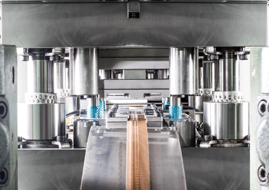
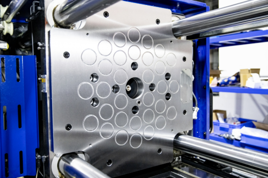
- Press (kuch qo'llash uskunasi): Mexanik, gidravlik yoki servodan boshqariladigan bo'lsin, press tekis materialni shaklli detallarga aylantirish uchun kerakli nazorat qilinadigan kuchni ta'minlaydi. Zamonaviy presslar juda aniq aniqlikda yuzlab yoki hatto minglab tonna kuch hosil qilishi mumkin.
Buni quyidagicha tasavvur qiling: qo'g'oz metall — bu sizning tabloingiz, kalıp — bu haykaltaroshning asbobidir va press esa barchasini amalga oshirish uchun zarur kuchni beradi. Ushbu elementlarning birortasini olib tashlasangiz, tizim oddiygina ishlamay qoladi.
Tekis materialdan yakuniy detalgacha
Demak, bu amalda qanday ko'rinishda? Masalan, po'latdan iborat bir g'ildirak (koyl) presga uzatilmoqda. Material mos holatga o'tkaziladi, unda pressning strelkasi (ram) ulkan kuch bilan pastga tushib, uruvchi (punch) ni kalıbning o'rniga (cavity) surib kiradi. Shu soniya qismida tekis metall kesiladi, shakllanadi yoki kalıbning aniq geometriyasiga muvofiq shakllanadi. Strelka (ram) orqaga qaytadi, tayyor detallar chiqariladi va sikl takrorlanadi — ba'zan daqiqasiga yuzlab marta.
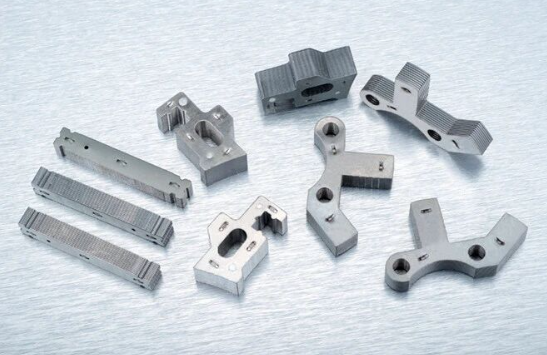
Bosib chiqarishning keng tarqalgan misoli — avtomobil qo'llab-quvvatlovchi qismlarini ishlab chiqarishdir. Bu, ko'rinib turibdiki, oddiy detallar avtomobil xavfsizligi talab qiladigan o'lchamlar aniqligini va struktural integritetini ta'minlash uchun ehtiyotkorlik bilan loyihalangan uskunalar talab qiladi. Sohani mutaxassislari aytishicha, matritsaning aniqligi bosib chiqarilgan detallarning sifati va takrorlanuvchanligiga to'g'ridan-to'g'ri ta'sir qiladi — yomon ishlab chiqilgan uskunalar noaniqliklarga sabab bo'lishi va chiqindilar ulushini oshirishi mumkin, aks holda, aniq ishlab chiqilgan matritsalar tozalik bilan kesish va qattiq o'lchovlar doirasini ta'minlaydi.
Bu asos — ishlov berilayotgan detallar, matritsa va press o'rtasidagi o'zaro ta'sirni tushunish — keyingi barcha jarayonlarga tayyorgarlik ko'rsatadi. Siz matritsa turlarini, material tanlovi yoki texnik xizmat ko'rsatish strategiyalarini o'rganayotgan bo'lsangiz ham, barcha narsa bu uchta ustunning birgalikda ishlashiga qaytadi. Bosib chiqarish — bu masshtabli aniq ishlab chiqarishdir va bu aniqlik to'g'ri loyihalangan va yaxshi ta'minlangan uskunalar bilan boshlanadi.
Bosib chiqarish matritsa tizimlarining asosiy komponentlari
Endi siz metall kesishning uchta ustunini tushunganingizdan so'ng, kesish shabloni (die) tarkibiy qismlariga chuqurroq kirib boramiz. Shablonni aniqlik asbobi sifatida tasavvur qiling — uning har bir qismi muhim rol o'ynaydi va bu qismlarni tushunish shablon loyihalash, texnik xizmat ko'rsatish yoki nosozliklarni aniqlash bilan shug'ullanadigan har qanday kishiga zarur.
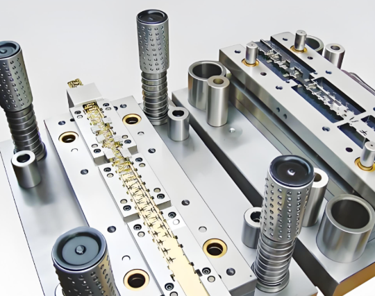
Kesish shabloni (stamping die) faqat bitta asbob emas — bu har bir elementi mutlaqo sinxron ishlashi kerak bo'lgan e'tiborli loyihalangan birlashma. Ishlab chiqaruvchi shunday deb aytadi, shablonning alohida qismlarining loyihasi, materiali va butunligi umumiy ishlash samaradorligi va ishlay olgan muddati uchun 90 foizdan ortiq miqdorda javob beradi. Bu juda katta raqam bo'lib, shuning uchun ushbu asosiy tushunchalarni tushunishning qanchalik muhim ekanligini ta'kidlamoqda.
Quyida ko'pincha kesish shablonlarida uchraydigan asosiy tarkibiy qismlar keltirilgan:
- Teshgichlar: Metall varaqqa bosib tushadigan erkak (maydon) shakllantiruvchi asboblar. Ular burilish, kesish yoki shakllantirish operatsiyalarini amalga oshiradi — bu ularning uch qismi (nose) shakliga va loyihaga qarab farq qiladi.
- Shablonlar (Die Buttons): Qarama-qarshi kesish qirrasi ta'minlaydigan ayol qabul qiluvchi bo'shliqlari. Qalpoqcha profilining qalinligi aniq tozalikda — odatda material qalinligining 5–10% — bilan kesuvchi tirnoq profiliga mos keladi.
- Chizgichlar: Har bir operatsiyadan keyin metallarni kesuvchi tirnoqlardan olib tashlaydigan yoki "stripping" (ajratib olish) vazifasini bajaradigan, prujinali plastinkalar. Agar striperlar bo'lmasa, material tirnoqqa yopishib qoladi va ishlab chiqarishni to'xtatadi.
- Pilotlar: Har bir press urishidan oldin material lentalarini to'g'ri joylashtirishni ta'minlaydigan tekislash yo'nalish beruvchilari. Ular aniqlik bir nechta stansiyalarda kumulyativ ravishda oshib boradigan progressiv kalıplarda juda muhimdir.
- Yo'nalish tiqinlari va bushinglar: Yuqori va pastki kalıp poydevorlarini ajoyib aniqlikda tekislash uchun 0,0001 dyuym (2,54 mikrometr) lik toleransiya doirasida aynan ishlab chiqarilgan, aniq silliqlangan komponentlar.
- Matritsa poydevorlari: Barcha ishchi kalıp komponentlarini o'rnatish uchun asos vazifasini bajaradigan — odatda po'lat yoki alyuminiydan tayyorlangan — poydevor plastinkalari.
Uyushib ishlaydigan tirnoqlar va kalıplar
Qo'lingizni qo'pol qilishni tasavvur qiling—bir qo'l urishni, ikkinchisi esa matritsa bo'shlig'ini ifodalaydi. Qog'oz kesish uskunasi ishlay boshlaganda, shu tamoyil qo'llaniladi, lekin kuchlar tonnalarda, aniqlik esa mikronlarda o'lchanadi.
Qattiqroq qilingan urish qismi (punch) o'chirgich plastinkasidan (stripper plate) o'tib, uning pastida joylashgan matritsa tugmachasiga (die button) tushadi. Urish qismi va matritsa o'rtasidagi nazorat qilinadigan bo'shliq—"matritsa sinishi" (die break)—tozalikni ta'minlaydigan kesish amaliyotini qo'llab-quvvatlaydi. Bo'shliq juda tor bo'lsa, ortiqcha issiqlik hosil bo'ladi va tezroq yaxshilanish sodir bo'ladi. Bo'shliq juda keng bo'lsa, qirralar (burrs) va o'lchamlarning noaniqliklari paydo bo'ladi. Moeller Precision Tool ma'lumotlariga ko'ra, bu bo'shliq odatda urish qismi uchining (punch nose) o'lchamidan kesilayotgan material qalinligining 5–10% ga ortiq bo'ladi.
Metall ushbu mos keladigan komponentlar orqali matritsada shakllantirilganda, natijada uskuna geometriyasiga aniq mos keladigan detallar hosil bo'ladi. Ushbu tizimning ajoyib tomoni — takrorlanuvchanligidir: bir marta to'g'ri sozlangandan keyin, qog'oz kesish matritsasi (stamping die) bir xil sifatda minglab yoki millionlab bir xil detallarni ishlab chiqarishi mumkin.
Aniqlikni ta'minlaydigan qo'llab-quvvatlovchi komponentlar
Chuqur kesish uchun ishlov beruvchi va ishlov beriladigan detallar ko'pincha e'tibor markazida bo'lsa-da, qo'llab-quvvatlovchi komponentlar sizning ishlab chiqarish jarayoningiz muvaffaqiyatli o'tishini yoki texnik xizmat ko'rsatish muammolariga aylanishini aniqlaydi.
Yo'naltiruvchi simlar va bushinglar maxsus e'tiborga loyiq. Ushbu aniq grindlangan komponentlar ikkita asosiy usulda ishlab chiqariladi: aluminium-bronza bushinglarga siljish orqali ta'sir qiladigan ishqalanishli simlar hamda yuqori tezliklarda ishqalanishni kamaytirish uchun aylanuvchi podshipniklarda harakatlanadigan sharli podshipnikli simlar. Sanoat mutaxassislari aytishicha, yo'naltiruvchi simlar 0,0001 dyuym (ya'ni o'ndan bir minginchi dyuym) lik aniqlikda ishlab chiqariladi. Bu darajadagi aniqlik har bir urishda yuqori va pastki kalıp qismlarining mutlaqo mos kelishini ta'minlaydi.
Kalıplar butun montajning tuzilish asosini tashkil qiladi. Ular po'lat yoki alyuminiydan yasalgan va ularga aniq tolerebtsiyalarda tekis va parallel qilish kerak. Quyi kalıp pressning ustida o'rnatiladi, yuqori kalıp esa pressning harakatlanuvchi qismiga (ram) biriktiriladi. Birgalikda ular yo'naltiruvchi simlari bilan birga "kalıp to'plami" deb ataladigan narsani hosil qiladi — bu barcha detallarni bir-biriga biriktirib turadigan skelet.
Keyin siz e'tibor bermasligingiz mumkin bo'lgan, lekin nimadir noto'g'ri ketganda diqqatingizni jalb qiladigan komponentlar bor:
- Chillqlar: Azot gazli, spiral yoki uretanli bo'lsin, ulardan chiqarish, siqish va tortish operatsiyalari uchun zarur kuchni ta'minlashda sprindlar ishlatiladi.
- Ushtavkalar: Sharchali qulflar (ball-lock) kalıpnig butunlay dismantl qilmasdan ham texnik xizmat ko'rsatish uchun tezda urish qismlarini olib tashlash imkonini beradi.
- Tizza bloklari: Ular kesish va shakllantirish paytida yon bosimni so'ngib oladi, yo'naltiruvchi simlarning egilishini oldini oladi va moslikni saqlaydi.
- Qo'llab-quvvatlovchi plastinkalar: Ular urish qismlari va kalıp tugmachalari orqasida qo'yilgan qattiqroq qilingan plastinkalar bo'lib, kuchlarni tarqatish va deformatsiyalarni oldini olish uchun mo'ljallangan.
Bu chiqarish kalıplari komponentlarining integratsiyalangan tizim sifatida qanday o'zaro ta'sirlashishini tushunish sizni oddiygina uskunalarni boshqaruvchi shaxsdan, ishlash samaradorligini optimallashtirish, muammolarni aniqlash va asboblar yaroqlilik muddatini uzaytirish qobiliyatiga ega bo'lgan mutaxassisga aylantiradi. Bu asos yaratilgandan so'ng, siz turli xil kalıp konfiguratsiyalarini va ularning har birining ishlab chiqarish talablaringiz uchun qachon eng maqsadga muvofiq bo'lishini o'rganishga tayyorsiz.
Progressiv kalıplar vs Transfer kalıplar vs Murakkab kalıplar
Siz chiqarish kalıplarining qanday qilib yasalishini ko'rdingiz — endi muhim savol: siz haqiqatan ham qaysi turdagi kalıpdan foydalanasiz? Javob sizning detallaringizning murakkabligiga, ishlab chiqarish hajmiga va byudjet cheklovlaringizga bog'liq. Noto'g'ri kalıp konfiguratsiyasini tanlash oddiy detallar uchun kalıplarga ortiqcha xarajat qilish yoki murakkab montajlarda sifat standartlarini bajarishda qiyinchiliklarga duch kelishni anglatadi.
Dey stempillash operatsiyalari bo'ylab to'rtta asosiy dey konfiguratsiyasi mavjud. Har biri alohida maqsadlarga xizmat qiladi va ularning farqlarini tushunish sizga aqlli uskunalar sotib olish imkonini beradi. Larson Tool kompaniyasiga ko'ra, to'g'ri dey turini tanlash ishlab chiqarish loyihasining muvaffaqiyatiga juda muhimdir, chunki har bir deyning o'ziga xos qobiliyatlari, narxlari va texnik xizmat ko'rsatish talablari mavjud.
Yuqori hajmli samaradorlik uchun ketma-ket matritsalar
Metal lenta bir nechta ish stansiyalari orqali harakatlanayotganini tasavvur qiling — bu yerda teshik punchlanadi, shu yerda qo'rqich egiladi, oxirida yakuniy shakl kesiladi. Bu — progressiv dey va stempillashning amalga oshirilishi.
Progressiv deylar bir xil dey to'plamida ketma-ket joylashtirilgan bir nechta stansiyalardan iborat. Metal lenta press orqali oldinga siljiganda, har bir stansiya biror amalni bajaradi, ya'ni yakuniy stansiyada tayyor detallar ajralib chiqadi. Bu usul bir qancha afzalliklarga ega:
- Tezlik: Bir marta press bosish bilan bir dona tayyor detallar hosil bo'ladi, bu esa soatiga yuzlab yoki hatto minglab detallarni ishlab chiqarish tezligini ta'minlaydi.
- Bir xillik: Barcha operatsiyalar bitta matritsada amalga oshirilgani uchun detaldan detalga o'zgarish minimal darajada qoladi.
- Qo'lda ishlash kamaytirildi: Lenta materiali avtomatik ravishda uzatiladi, bu esa operatsiyalar orasida qo'lda uzatishni yo'q qiladi.
Nima uchun? Progressiv matritsalar boshlang'ich loyihalash va sozlash xarajatlari yuqori talab qiladi. Ushbu matritsalar va to'g'rilash tizimlarining murakkab tabiati ehtiyotkorlik bilan rejalashtirish va aniq muhandislikni talab qiladi. Biroq, katta ishlab chiqarish hajmlarida bir dona detaldan tashkil topgan xarajat sezilarli darajada kamayadi — bu konfiguratsiya uzoq muddatli, yuqori hajmli loyihalar uchun juda arzon variant bo'lib qoladi.
Progressiv konfiguratsiyadagi po'lat to'g'rilash matritsalari avtomobilsozlikda ayniqsa keng tarqalgan, chunki millionlab birliklar uchun doimiy sifat talab qilinadigan qismlar, masalan, qo'llab-quvvatlovchi qismlar, qisqichlar va strukturalik mustahkamlashlar ishlab chiqariladi. Agar siz yuqori hajmli ilovalar uchun avtomobil to'g'rilash matritsalari ishlab chiqarsangiz, progressiv sozlamalar ko'pincha eng yaxshi investitsiya qaytishini ta'minlaydi.
Transfer matritsalari: Murakkab detallar uchun moslashuvchanlik
Agar sizning detalingiz progressiv to'g'rilash uchun juda katta yoki juda murakkab bo'lsa, nima bo'ladi? Bu vaziyatda transfer matritsalari yechimni taklif etadi.
Qismlar lentani har bir stansiyadan o'tkazib yuboradigan progresiv kalıplardan farqli o'laroq, transfer kalıplari diskret qo'llanmalarini alohida ish stansiyalari orasida harakatlantirish uchun mexanik barmoqlar yoki robotlashtirilgan tizimlardan foydalanadi. Bu usul quyidagi hollarda ajoyib natija beradi:
- Qismlar chuqur tortish yoki murakkab uch o'lchovli shakllantirishni talab qilganda
- Tarkibiy qismning o'lchami lentadan o'tkazib ishlashni amalga oshirishni noqulay qilganda
- Bir nechta operatsiyalarga mustaqil sozlash yoki vaqt belgilash kerak bo'lganda
Transfer kalıplari o'zlarining murakkab transfer mexanizmlari tufayli yuqori kalıp ishlab chiqarish va sozlash xarajatlarini talab qiladi. Ular ko'p turdagi qismlarni ishlashda mos keladigan va murakkab qismlarni qayta ishlash qobiliyatini ta'minlaydigan o'rta va yuqori ishlab chiqarish hajmlari uchun eng yaxshi tanlovdir. Aero kosmik sanoat va og'ir mexanika kabi sohalarda murakkab geometriyalarga ega aniq o'lchovlarga ega keng ko'lamli montajlar uchun transfer tizimlariga tayaniladi.
Murakkab va Birikma Kalıplar: Soddalikda samaradorlik
Har bir ilova progressiv yoki o'tkazish usulidagi qoliplarga murakkablik talab qilmaydi. Murakkab qoliplar bitta press urishida bir nechta operatsiyalarni — odatda bo'shatish va shakllantirish kabi kesish operatsiyalarini — bajaradi.
Samarali ekanligi ajoyibmi? Ha, shunday. Murakkab qoliplar oddiyroq detallar uchun bir nechta afzalliklarga ega:
- Qolip narxining pastligi: Oddiyroq dizayn boshlang'ich investitsiyani kamaytiradi
- A'lo tekislik: Ikkala tomondan bir vaqtda kesish minimal distorsiyaga sabab bo'ladigan tekis bo'shatmalarni hosil qiladi
- Qattiq to'g'ri kelishlar: Bitta urishli operatsiya ketma-ket joylashish xatolarini yo'q qiladi
Murakkab qoliplar kesish operatsiyalari ustunlik qiladigan tekis, nisbatan oddiy komponentlar uchun eng yaxshi natija beradi. Masalan, murakkab shakllantirish talablari bo'lmagan g'ildiraklar, shimlar yoki tekis qo'llab-quvvatlovchi qismlar.
Kombinatsiya shablonlari bu tushunchani bir xil shablon to'plamida kesish va shakllantirish operatsiyalarini birlashtirish orqali yanada rivojlantiradi. Murakkab shablonlar kesishga e'tibor qaratgan bo'lsa, kombinatsiya shablonlari detalni kesib chiqish va qo'rqichni egishni bir vaqtda amalga oshirishi mumkin. Bu g'ibrid yondashuv oddiy murakkab shablonlar va murakkabroq progressiv tizimlar o'rtasidagi bo'shliqni to'ldiradi.
Kalıp turi bilan ishlab chiqarish talablari mosligi
Qanday tanlash kerak? Quyidagi qaror qabul qilish omillarini hisobga oling:
- Qism murakkabligi: Oddiy tekis detallar murakkab shablonlarga afzalilik beradi. Egilishlar, tortishlar yoki rel'efli bezaklar bilan ko'p xususiyatlarga ega detallar progressiv yoki o'tkazish konfiguratsiyalariga intiladi.
- Ishlab chiqarish hajmi: Yuqori hajmlar progressiv shablonlarga investitsiya qilishni oqlaydi. Past hajmlar esa dastlabki xarajatlari pastroq bo'lgan murakkab yoki kombinatsiya yondashuvlarini afzal ko'rishadi.
- Tolerantlik talablari: Bir nechta xususiyatlarga nisbatan aniq tolereanslar ko'pincha barcha operatsiyalar bir xil joylashish nuqtalariga mos keladigan progressiv shablonlarni talab qiladi.
- Detal o'lchami: Katta detallar odatda o'tkazish shablonlarini talab qiladi. Kichikdan o'rtacha kattalikdagi detallar progressiv tizimlarda yaxshi ishlaydi.
Quyidagi jadval har bir shablon turi asosiy qaror qabul qilish omillari bo'yicha qanday taqqoslanishini umumlashtiradi:
| Shablon turi | Eng yaxshi dasturlar | Haqiqiy hajm | Murakkablikni boshqarish | Nisbiy narx |
|---|---|---|---|---|
| Progressiv oʻlimlar | Ko'p funksiyali qismlar, qo'llab-quvvatlovchi qismlar, qisqichlar, ulagichlar | Yuqori hajm (100 000+ detallar) | Yuqori — kesish, shakllantirish, egilishni ketma-ket bajaradi | Boshlang'ich xarajatlar yuqori, har bir detalgina arzon |
| Transfer shablonlari | Katta qismlar, chuqur chizilgan detallar, murakkab montajlar | O'rtacha va yuqori hajm | Juda yuqori — mustaqil stansiyalarning moslashuvchanligi | Eng yuqori dastlabki va sozlash xarajatlari |
| Комплекс ускуна | Tekis qismlar, mutaxassislarning g'ildirakchasi, oddiy bo'shliqlar | Past va o'rtacha hajm | Past — asosan kesish operatsiyalari | Eng past dastlabki xarajatlar |
| Birikma pres-formalari | Kesish va cheklangan shakllantirish talab qiladigan qismlar | Past va o'rtacha hajm | O'rtacha — kesish va oddiy shakllantirish | O'rtacha dastlabki xarajatlar |
Masalan, avtomobil qismlarini chiqarish uchun matritsalar talablarini baholaganda, ko'pchilik yuqori hajmli korpus komponentlari va konstruktiv qismlar progressiv tizimlardan o'tadi. Biroq, eshik qoplamalari yoki kapot montajlari kabi katta panellarga ularning o'lchami va chuqur chizish talablari tufayli o'tkazish matritsalari ishlatilishi mumkin.
Asosiy xulosa shundaki, universal "eng yaxshi" matritsa turi yo'q — faqat sizning aniq ilovangiz uchun to'g'ri matritsa mavjud. Bu farqlarni tushunish sizga uskunalar yetkazib beruvchilari bilan samarali muloqot qilishga va dastlabki investitsiyani uzoq muddatli ishlab chiqarish iqtisodiyotiga muvozanatlashga imkon beradigan axborotlangan qarorlar qabul qilishda yordam beradi. Matritsa tanlash prinsiplarini egallaganingizdan so'ng, keyingi muhim masala — sizning uskunalaringiz qanday materiallardan tayyorlanishi kerak?
Ishlash samarasini belgilovchi uskuna materiallari
Siz o'zining matritsa turini tanlagansiz — lekin bu matritsa aslida nimadan tayyorlanishi kerak? Bu savol ko'pincha e'tibordan qoladi, ammo materialni tanlash vosita xizmat muddati, detallar sifati va sizning foydangizga bevosita ta'sir qiladi. Noto'g'ri tanlov — vositada erta yeyilish, kutilmagan to'xtash va almashtirish xarajatlari ortib borishiga sabab bo'ladi. Aqlli tanlov — sizning metall kesish vositangiz millionlab sikllar davomida ishonchli ishlaydi.
Haqiqat shundaki: har bir ilovaga mos keladigan yagona "eng yaxshi" material yo'q. Ideal tanlov sizning kesiladigan materialingizga, ishlab chiqarish hajmiga, talab qilinadigan aniqlik darajasiga va byudjet cheklovlaringizga bog'liq. Keling, tanlovlarni tushuntirib beramiz, shunda siz axborotlangan qaror qabul qilishingiz mumkin.
Qo'llaniladigan qoliplar uchun po'lat darajalari va ularning qo'llanilishi
Texnika po'latlari aksariyat chiqarish qo'llanmalarida ishchi material sifatida qolmoqda. Nifty Alloys ma'lumotlariga ko'ra, texnika po'lati — bu o'ziga xos qattiqlik, sirpanishga chidamlilik va yuqori haroratlarda ham o'tkir kesuv qirrasi saqlash qobiliyati bilan ajralib turadigan uglerodli va qotishma po'latlarining maxsus oilasidir. Bu materiallar xrom, vanadiy, molibden va volfram kabi karbid hosil qiluvchi elementlardan iborat bo'lib, ular shakllantirish, kesish va shakl berish jarayonlari uchun idealdir.
Sizning chiqarish operatsiyalaringiz uchun po'lat asbob-uskunalarni tanlaganingizda, bir nechta keng tarqalgan darajalarga duch kelasiz:
- D2 po'lati: Yuqori xrom miqdori tufayli ajoyib sirpanishga chidamlilikka ega bo'lgan sovuq ish uchun mo'ljallangan texnika po'lati. D2 po'lati — kesish matritsalari, chiqarish asbob-uskunalari va kesuv pichaklari uchun standart tanlovdir. Biroq, u ba'zi boshqa variantlarga nisbatan qiyinroq ishlanadi va nozikroqdir.
- A2 po'lati: D2 ga nisbatan yuqori chidamlilik beradi, lekin yaxshi abraziv chidamlilikni saqlaydi. A2 po'lati kesish operatsiyalari bilan birga o'rta darajadagi urilish yuklamasiga duch keladigan asboblaringizda yaxshi ishlaydi.
- O1 po'lati: Mashinada qayta ishlash oson bo'lgan va past hajmli ishlar yoki namunalar tayyorlash uchun ishonchli ishlashni ta'minlaydigan moyda quyuvchi darajali po'lat.
- M2 Yuqori tezlikdagi po'lat: Yuqori haroratlarda ham qattiqlikni saqlaydi, shu sababli ishqalanish natijasida issiqlik ajralib chiqadigan yuqori tezlikda ishlaydigan progressiv asboblar uchun idealdir.
Qo'llanilishi qiyin bo'lgan vaziyatlarda PM M4, ASP 23 va CPM 10V kabi changli metallurgiya po'latlari muhim afzalliklarga ega. Quyidagi to'liq materiallar tavsifi da aytib o'tilganidek, bu darajalar mikrostrukturasining bir xilligi va singanlik xavfi minimal bo'lganligi bilan ajralib turadi — murakkab shakllar, uzoq muddatli ishlab chiqarish va yuqori tezlikda chaplash uchun a'lo hisoblanadi. Ular odatdagi po'latlarga qaraganda ancha uzoqroq xizmat qiladi, lekin narxlari yuqori.
Aniq ishlov beriladigan materiallar uchun po'latdan yasalgan chaplash asboblarini tanlash qanday amalga oshiriladi? Bu yerda tanlov ancha nozik bo'ladi:
- Alyuminiy uchun: Yumshoq material, lekin yopishuvga moyil. Tavsiya: PVD qoplamali A2 yoki M2. Kalit — past ishqalanish koeffitsiyenti va silliq sirtga erishish.
- Yuqori mustahkamlikdagi po'latlar (DP, CP) uchun: Mustahkamlikning oshishi vositalarga qo'yiladigan talablarni oshiradi. D2, PM M4 yoki ASP 23 — optimallashtirilgan geometriya va qoplamalar bilan.
- Ultra yuqori mustahkamlikdagi po'latlar (TRIP, martensitli) uchun: Juda qiyin vazifa. ASP 30, CPM 10V yoki karbid kesuv qismlari kerak bo'ladi — bunday yuqori sifatli materiallarsiz vositalarning erta buzilishi tez-tez uchraydi.
Aluminiy chaplash vositalariga maxsus e'tibor berish kerak. Aluminiy detallari po'latga nisbatan yumshoq bo'lsa-da, ular o'ziga xos qiyinchiliklarga sabab bo'ladi. Agar sirt sharoitlari va bo'shliqlar mos ravishda sozlanmasa, materialning qoplamasi va galling jarohatlari vositalarga ham, detallarga ham zarar yetkazishi mumkin.
Karbid va qoplamalar qachon maqsadga muvofiq bo'ladi
Ba'zan po'latdan yasalgan vositalar etarli emas. Siz abrasiv materiallarni qayta ishlamoqda, juda yuqori hajmda ishlamoqda yoki uzun ishlab chiqarish davomida aniq toleranslarga ega bo'lishni talab qilmoqda — shunda volfram karbid haqida fikr yuritish boshlanadi.
Ga binoan Endurance Karbid , volfram karbidi po'latdan ikki baravar qattiq — bu uni aniq ishlov berish sohalari uchun juda qadrlanadi. Bu uchta asosiy afzallikka olib keladi:
- Ajoyib mustahkamlik: Karbidning qattiq va yaxshi chidamliligi punch ustidan yuqori nazorat qilish imkonini beradi va uning almashtirilishi kamroq bo'ladi.
- Kengaytirilgan Ish Jamiysi: Karbid punchlarni po'latdoshlariga qaraganda ancha kamroq tezlikda almashtirish kerak. Boshlang'ich xarajatlar yuqori bo'lsa ham, almashtirish chastotasining kamayishi karbidni vaqt o'tishi bilan arzonroq qiladi.
- Kuchaytirilgan productivity: Har bir almashtirish — ishlanish to'xtashi demakdir. Karbidning durabiliteti uzilishlarni minimal darajada saqlaydi va sizning presslaringiz doim ishlashini ta'minlaydi.
K10, K20 va K30 kabi karbid darajalari qattiqlik va chidamlilik jihatidan turli muvozanatlarga ega. K10 kesish ishlarida maksimal qattiqlikni ta'minlaydi, K30 esa zarba yuklamasi ta'sir etadigan ishlarda yaxshilangan urilish chidamliligini ta'minlaydi. Ko'pchilik ishlab chiqaruvchilar karbidni qo'yilma shaklida ishlatadi — qattiq kesuvchi yuzani mustahkamroq po'lat yadrosi bilan birlashtirib.
Yuzaki qoplamalar — bu karbid asboblar sotib olishga to'liq investitsiya qilmasdan asboblar yaroqlilik muddatini uzaytirishning yana bir kuchli usuli. Odatda qo'llaniladigan qoplamalar quyidagilardir:
- TiN (Titan Nitrid): Sirtning abraziv chidamliligini oshiruvchi va ishqalanishni kamaytiruvchi oltin rangli qoplama. Arzon va keng qo'llaniladi.
- TiCN (Titan karbonitrid): TiN dan qattaroq, abraziv materiallarda yaxshi ishlash xususiyatiga ega.
- DLC (Diamond-Like Carbon): Juda qattiq, ishqalanish koeffitsienti juda past — materialning qoplanishiga e'tibor beriladigan aluminium ishlov berishda ajoyib natija beradi.
- AlCrN (Alyuminiy-xrom nitriddir): Yuqori tezlikda ishlashda yuqori issiqlik chidamliligi.
Bu qoplamalar PVD (Fizik bug'lanish usuli) yoki CVD (Kimyoviy bug'lanish usuli) texnologiyalari bilan qo'llaniladi; ular faqat mikron qalinlikda qo'llanilsa ham sirt xususiyatlarini keskin yaxshilaydi.
Quyidagi jadval sizning material variantlaringizni umumlashtiradi va tanlovni yo'naltiradi:
| Material | Asosiy xususiyatlari | Eng yaxshi dasturlar | Nisbiy chidamlilik | Narx darajasi |
|---|---|---|---|---|
| D2 O'qish Po'lati | Yuqori abraziv chidamlilik, yaxshi kesish qirrasi saqlanishi | Chiqarish, teshish, umumiy shakllantirish | Yaxshi | O'rtacha |
| A2 Asbobli Po'lat | Muvozanatli qattiqlik va chidamlilik | O'rtacha zarba yuklamalari, shakllantirish | Yaxshi | O'rtacha |
| M2 yuqori tezlikdagi po'lat | Issiqlikga chidamlilik, haroratda qattiqlikni saqlash | Yuqori tezlikdagi progressiv kalıplar | Judada yaxshi | O'rtacha-yuqori |
| PM po'latlar (ASP 23, CPM 10V) | Bir xil tuzilish, trog'likka chidamlilik, uzun foydalanish muddati | Murakkab shakllar, uzoq muddatli ishlatish, UHSS chop etish | Ajoyib | Yuqori |
| Tungsten Carbide | Po'latdan ikki baravar qattiq, ajoyib chidamlilik | Yukori hajmli, abraziv materiallar, aniq kesish chetlari | Ajib | Eng yuqori |
| Qoplamali asbob po'lati (TiN, TiCN, DLC) | Po'lat asosda yaxshilangan chidamlilik va ishqalanishni kamaytirish | Uzunroq ish vaqtlari, alyuminiy shakllantirish, gallingni kamaytirish | Po'lat asosga nisbatan yaxshilangan | O'rtacha qo'shimcha narx |
Asosiy natija? Material tanlovi — bu faqat xarid qilish ro'yxati bo'lmagan, balki strategik qaror. Ishlab chiqarish hajmlarini, ishlov beriladigan materiallarni, aniqlik talablarini va umumiy egallash xarajatlarini (faqat boshlang'ich narxni emas) hisobga oling. Besh marta uzoqroq xizmat qiladigan qimmatroq shakllantirish vositasi materiali ko'pincha tez-tez almashtiriladigan arzon variantga qaraganda iqtisodiy jihatdan afzal natija beradi.
Shakllantirish vositalari materiallari haqida tushunchaga ega bo'lganingizdan so'ng, keyingi qadam — ushbu komponentlarning dastlabki konseptsiyadan ishga tayyor shakllantirish vositasigacha bo'lgan dizayn jarayoni orqali qanday birlashishini o'rganishdir.
Shakllantirish shabloni dizayni jarayoni tushuntirildi
Siz o'zining matritsa turini tanlagansiz va uskunalar materiallarini tanlagansiz — lekin matritsa aslida qanday yaratiladi? G'oya eskizi dan ishga tayyor uskunagacha bo'lgan yo'l bir nechta diqqatli tartibda amalga oshiriladigan bosqichlardan iborat, ulardan har biri oldingisiga tayanadi. Biror bosqichni o'tkazib yuborish yoki tekshirishni tezlashtirish — bu qimmatga tushadigan qayta ishlash, ishlab chiqarish kechikishi va talablarga mos kelmaydigan detallarga olib keladi.
Haqiqat shundaki, muvaffaqiyatli matritsa loyihasi murakkablikni ishlab chiqarish jarayonini silliq o'tkazish uchun muhandislik bosqichiga oldindan yuklaydi. Mekalite ma'lumotlariga ko'ra, metall matritsasining loyihalash aniqiligi va sifati oxirgi detallarning sifatiga to'g'ridan-to'g'ri mutanosib — va birinchi marta to'g'ri loyihalash pul ham, vaqt ham tejaydi. Keling, ushbu muhim jarayoning har bir bosqichini ko'rib chiqamiz.
G'oya Eskizidan CAE Simulyatsiyasigacha
Uskuna va matritsa loyihalash hech qanday po'lat kesilmaguncha boshlanadi. Jarayon har bir bosqichi keyingisini aniqlaydigan mantiqiy ketma-ketlikda amalga oshiriladi:
- Detal tahlili va amal qilish mumkinligini baholash: Har bir loyiha detallarning o'zini loyihalashni tekshirishdan boshlanadi. Ushbu geometriya chiqarilishi mumkinmi? Material shakllanish jarayonida to'g'ri oqadimi? Muhandislar murakkab naqshlar, keskin radiuslar va yorilish yoki burishga sabab bo'lishi mumkin bo'lgan xususiyatlarni baholaydilar. Ushbu bosqichda keng qamrovli resurslarga katta sarmoya kiritilishidan oldin potensial muammolar aniqlanadi.
- Lenta tartibi ishlab chiqarish: Amal qilish mumkinligi tasdiqlangandan so'ng, muhandislar metall varaqning kalip orqali qanday harakatlanishini belgilaydilar. Lenta tartibi har bir kesish, egilish va shakllantirishni ketma-ketlikda ko'rsatadi — ya'ni metallning tekis materialdan yakuniy detalgacha bo'lgan yo'lini aslida rejalashtiradi. Yaxshi loyihalangan tartib chiqindilarni minimal darajada kamaytiradi va ishonchli uzatish hamda aniq joylashuvni ta'minlaydi.
- Kalip yuzi va mahkamlagich loyihalash: Ushbu bosqichda metall bilan aloqada bo'lib, uni deformatsiya qiladigan haqiqiy sirtlar modellashtiriladi. Chuqur tortish operatsiyalarida mahkamlagich sirtlari material oqishini nazorat qiladi va burishni oldini oladi. Bu yerda belgilangan geometriya materialning qanday cho'zilishi, qalinligining kamayishi va chiqarilish jarayonidagi shakllanishini bevosita belgilaydi.
- Kalıb tarkibiy qismlarining struktural dizayni: Shakllantiruvchi sirtlar aniqlanganidan so'ng, e'tibor to'liq kalıb tuzilishiga—kalıb poydevorlari, urg'uchlar, kalıb bo'shliqlari, bosim padlari va barcha qo'llab-quvvatlovchi tarkibiy qismlarga qaratiladi. Ayniqsa aniqlik talab qiladigan murakkab xususiyatlarga ega bo'lgan tarkibiy qismlar kerakli maydonchilikni ta'minlash uchun maxsus ishlab chiqarish jarayonlarini talab qilishi mumkin.
- CAE-simulyatsiya va tekshirish: Har qanday asbob po'latini kesishdan oldin zamonaviy cho'zish dizayni keng qamrovli kompyuter simulyatsiyasiga tayanadi. Cheklangan elementlar tahlili (FEA) dasturi virtual cho'zish jarayonini yaratadi va varaqsimon metallning qanday xulq-atvori namoyon bo'lishini bashorat qiladi—ya'ni u qayerda yorilishi, burilishi yoki ortiqcha ingichka bo'lishi mumkin. Bu raqamli tasdiqlash muammolarni dastlabki bosqichda, ya'ni o'zgartirishlar deyarli hech nima turmagan paytda aniqlaydi, bu esa jismoniy o'zgartirishlarga nisbatan juda arzonroqdir.
- Ishlab chiqarish: Tasdiqlangan dizaynlar qo'lga kelingandan so'ng, kalıb ishlash ishlari ishlab chiqarish zavodiga o'tadi. CNC frezalash, elektr-eroziya ishlash (EDM), aniq grindlash va issiqlik ishlashi xom ashyolarni yakuniy kalıb tarkibiy qismlariga aylantiradi. Har bir operatsiya muhandislik chizmalarida ko'rsatilgan maydonchiliklarga mos kelishi shart.
- Sinov va nosozliklarni bartaraf etish: Oxirida, yig'ilgan kalıp birinchi haqiqiy dunyo sinovini o'tkazish uchun pressga joylashtiriladi. Sinov nazariyaning amalda qanday ifodalanishini ko'rsatadi, shu bilan birga nosozliklarni bartaraf etish jarayoni simulyatsiya natijasida aniqlanmagan muammolarga e'tibor beradi. Bu takrorlanuvchi jarayon detallar doimiy ravishda barcha talablarga mos kelguncha davom etadi.
Zamonaviy CAE simulyatsiyasining kuchi ortiqcha ta'kidlamoqqa to'g'ri kelmaydi. Keysight kompaniyasi tomonidan aytib o'tilganidek, qog'oz metallni shakllantirish bo'yicha simulyatsiya "virtual kalıp sinovlarini" amalga oshirish imkonini beradi, bu esa jismoniy asbob-uskunalar yaratilishidan oldin nuqsonlarni aniqlay oladi. Bu qobiliyat rivojlantirish modelini fundamental darajada o'zgartiradi — "yaratish va sinovdan o'tkazish"dan "bashorat qilish va optimallashtirish"ga.
Bu amaliy jihatdan nima anglatishini hisobga oling: simulatsiyasiz muhandislar tajriba va sinov-xatolarga tayanardilar va shakllantiruvchi matritsaning haqiqiy ishlashi faqat uni yasab, pressga o'rnatgandan keyingina aniqlanardi. Bugun shakllantirish dasturlari metall kesilishidan oldin materialning cho'zilishini, ingichkalashishini va oqishini hisoblaydi. Masalan, shakllantirilgan detallar o'z dastlabki shakliga qaytib ketadigan "qaytish" hodisasi (springback) kabi muammolar matritsa loyihasiga o'zida bashorat qilinishi va kompensatsiya qilinishi mumkin.
Sinov va tasdiqlashning muhim ahamiyati
Eng murakkab simulatsiya ham cheklovlarga ega. Jismoniy sinov hali ham zarur, chunki u taxminlarni tasdiqlaydi, materialning haqiqiy xulq-atvorini ochib beradi va barcha komponentlarning mo'ljalga mos ishlashini tasdiqlaydi.
Sinov davomida muhandislar haqiqiy detallarni ishga tushirib, ularni texnik talablarga mosligi bo'yicha ehtiyotkorlik bilan tekshiradi. Ushbu bosqichda ko'pincha quyidagi muammolar hal qilinadi:
- Materialning boshqa tomonga og'ilishini kompensatsiya qilish: Matritsa geometriyasini sozlash — yakuniy detallarning o'lchamlari maqsadga mos kelishi uchun materialning qaytishini (spring-back) hisobga olish
- Vaqt sozlamalari: Press urish paytida turli die tarkibiy qismlarining materialga ta'sir qilishini sozlash
- Yuzasining sifati: Belgilar, xiziqchalar yoki gallingni yo'q qilish uchun die sirtlarini polirovka qilish yoki oraliqlarni sozlash
- Material oqimi: To'g'ri material tarqalishini ta'minlash uchun bog'lovchi bosimini yoki chiziqli to'siqlarning konfiguratsiyasini o'zgartirish
Maqsad — birinchi urinishda tasdiqlash darajasini iloji boricha yuqori qilishdir; ya'ni detallar keng qamrovli qayta ishlash sikllari talab qilmasdan texnik talablarga mos keladi. Sanoat yetakchilari bu ko'rsatkichni 90% dan yuqori darajaga yetkazishni amalga oshirishadi, lekin buning uchun jiddiy simulyatsiya, tajribali muhandislik va tizimli nosozliklarni aniqlash protokollari kerak.
Bu texnologik yutuqlar bilan qog'oz metallni chaplash loyihasi keskin rivojlanib bormoqda. Avvalgi davrda asbobsozlar fizik sinovlar uchun haftalab vaqt sarflashgan bo'lsa, simulyatsiya bu muddatni sezilarli darajada qisqartiradi va natijalarni yaxshilaydi. To'g'ri asbob va die loyihalashga kiritilgan investitsiya ishlab chiqarish davomida — doimiy sifat, chiqindi miqdorining kamayishi va millionlab sikllar davomida bashorat qilinadigan ishlash — orqali foyda beradi.
Metalni chiqarish uchun matritsa loyihasi asosan detallarning talablarini ishlab chiqarish tezligida ishonchli ishlaydigan uskunaga aylantirishga qaratilgan. Stripning joylashuvidan boshlab material tanlash va simulyatsiya parametrlarigacha bo'lgan loyihalash bosqichlarida qabul qilinadigan har bir qaror shu maqsadga erishishga ta'sir qiladi. Asosiy loyihalash tamoyillari o'rganilgandan keyin, alohida metalni chiqarish operatsiyalarining uskunaga qanday ta'sir qilishini tushunish keyingi muhim omil hisoblanadi.
Uskunani metalni chiqarish operatsiyalariga moslashtirish
Siz matritsalarni qanday loyihalash va ularni qanday materiallardan tayyorlash haqida bilib oldingiz — lekin alohida metalni chiqarish operatsiyalari aniq uskuna talablari sifatida qanday ifodalanadi? Aynan shu yerda nazariya amaliyotga aylanadi. Har bir operatsiya noyob konfiguratsiyalarni, aniq bo'shliqlarni va ehtiyotkorlik bilan materialni tanlashni talab qiladi. Agar bu tafsilotlarga e'tibor bermasangiz, qirralardagi burrlar, trog'lar yoki o'lchamlarning siljishi kabi muammolarga duch kelishingiz mumkin. Agar esa ularni to'g'ri bajarsangiz, sizning metalni chiqarish jarayoningiz ishlab chiqarish hajmlari bo'ylab silliq o'tadi.
Chop etish jarayoni metallarni turli xil usullarda shakllantiruvchi bir qator alohida operatsiyalarni o'z ichiga oladi. Fictiv ma'lumotlariga ko'ra, chop etish operatsiyalari asosan ularning asosiy harakati—kesish, shakllantirish yoki bitta matritsada ikkalasini ham birlashtirish—bo'yicha guruhlanadi. Har bir operatsiya uchun sizning vositalaringizdan nima talab qilinishini tushunish sizga dastlabki bosqichda to'g'ri konfiguratsiyalarni belgilash imkonini beradi.
Keng tarqalgan operatsiyalar uchun vositalar konfiguratsiyalari
Keling, asosiy chop etish operatsiyalarini va ularning sizning vositalaringizdan nima talab qilishini tahlil qilamiz:
Chiqarish va punchlash: Bu kesish operatsiyalari o'xshash ko'rinsa ham, bir muhim jihatda farq qiladi—siz qanday qismni saqlab qolishingiz. Chetlari kesilgan (blanking) operatsiyasi kesilgan qismni yakuniy detalingiz sifatida beradi, ya'ni kesilgan material detaldir; punchlash esa kesilgan joylarda teshiklar hosil qiladi va kesilgan material chiqindi hisoblanadi. Ikkala operatsiya ham quyidagilarga ega bo'lishini talab qiladi:
- To'g'ri aralashma bilan kesuvchi sharsho (odatda material qalinligining tomoniga 5–10%)
- Qattiqroq qilingan vosita po'latidan yasalgan punchlar—yuqori hajmda ishlatish uchun D2 yoki karbid
- Punch va matritsa tugmasi o'rtasidagi aniq moslik—tengsiz yeyilishni oldini olish uchun
Qog'oz metallni bosishda bo'shliq to'g'ridan-to'g'ri qirralarning sifatiga ta'sir qiladi. Juda tor bo'shliq qolgan qismlarga ortiqcha ishlashni keltirib chiqaradi va bosish kuchini oshirishni talab qiladi. Juda keng bo'shliq esa burrlar va aylanma qirralarni hosil qiladi, ularni qayta ishlash kerak bo'lishi mumkin.
Egish: Bu shakllantirish operatsiyasi materialni to'g'ri o'q bo'ylab deformatsiya qiladi. Asbob-uskunalar bilan bog'liq jihatlarga quyidagilar kiradi:
- Egish burchagi va materialga qarab V-simon yoki sochiladigan (wipe) matritsa konfiguratsiyalari
- Matritsaning geometriyasiga qo'shilgan elastiklik kompensatsiyasi — materiallar shakllantirilgandan keyin o'zlarining dastlabki shakliga qaytishga intiladi
- Egish radiuslari material qalinligiga mos keladi (po'lat uchun minimal ichki radius odatda material qalinligiga teng)
Sanoat mutaxassislari aytganidek, muhandislar matritsani qismni ortiqcha egish uchun loyihalash orqali elastiklik kompensatsiyasini hisobga olishlari kerak. Bu kompensatsiya materialga qarab o'zgaradi — yuqori mustahkamlikdagi po'latlar yumshoq po'latlarga nisbatan ko'proq elastiklik namoyon qiladi.
Rel'efli bosish va tangacha bosish: Bu operatsiyalar materialni kesmasdan ko'tarilgan yoki chuqurlikdagi elementlarni yaratadi. Rel'ef qilish — materialni yengil naqshlarga cho'zadi, bir paytda esa metallni aniq shakllarga oqizish uchun juda katta bosim qo'llaniladigan 'koin' (tangacha) operatsiyasi ishlatiladi. Talablar quyidagilardan iborat:
- Tozalangan matritsa sirtlari — aniq elementlarni aniqlash uchun
- Koin operatsiyalari uchun yuqori bosimli presslar
- Material oqimini diqqat bilan nazorat qilish — ingichkalashish yoki yorilishni oldini olish uchun
Flanets: Bu operatsiya materialni egri chiziq bo'ylab egadi yoki teshiklar atrofida ko'tarilgan chet hosil qiladi. Uskunalar talablari quyidagilardan iborat:
- Keng qo'rqinlar uchun ko'p bosqichli progressiv shakllantirish
- Cho'zilgan qo'rqinlar — chetlarning yorilishini oldini olish uchun material oqimini nazorat qilishni talab qiladi
- Siyqilgan qo'rqinlar — burmalar hosil bo'lmasligi uchun material siyqilishiga joy ajratishni talab qiladi
Chuqur tortish: Tekis blanklardan stakan shaklidagi yoki bo'shliqli detallarni yaratish maxsus uskunalar talab qiladi:
- Material oqimini nazorat qilish uchun tortish halqalari va mahkamlagichlar
- Matni die bo'shlig'iga qanday kirishini boshqaradigan chizish sharni
- Bo'sh diametridan chuqurroq detallar uchun bir nechta chizish bosqichlari
Quyidagi jadval ushbu operatsiyalarni ularning aniq asbob-uskuna talablari bilan moslashtiradi:
| Operatsiya | Asosiy ta'sir | Asosiy asbob-uskuna talablari | Muhim bo'shliq/toleransiya | Oddiy qoʻllanmalar |
|---|---|---|---|---|
| Bo'shlik | Kesish (kesilgan qismlarni saqlash) | Qattiqroq qilingan punch/die, o'tkir qirralar, to'g'ri striper | material qalinligining 5-10% | G'altaklar, qo'llab-quvvatlovchi qismlar, tekis komponentlar |
| Chiqitish | Kesish (teshiklar yaratish) | Qattiqroq qilingan punch, die tugmasi, pilot moslashuvi | material qalinligining 5-10% | O'rnatish teshiklari, ventilyatsiya naqshlari |
| Bukish | Shakllantirish (chiziqli o'q) | V-simvolli yoki tozalash simvolli matritsa, elastiklik qaytishini kompensatsiya qilish | Minimal radius = material qalinligi | Qo'llab-quvvatlovchi qismlar, kanallar, qopqonlar |
| Embosholish | Shakllantirish (yuzaki xususiyatlar) | Polirlangan matritsalar, nazorat qilinadigan cho'zilish | Xususiyat chuqurligi odatda qalinlikning 50% dan kam | Logotiplar, qattiqroq qiluvchi rebrlar, bezak naqshlari |
| Monda o'rnatish | Shakllantirish (aniq xususiyatlar) | Yuqori tonnajli, qattiqroq qoliplar, polirlangan sirtlar | Aniq o'lchov nazorati (±0,001") | Tangalar, aniq detallar, elektr kontaktlari |
| Tirgak o'rnatish | Shakllantirish (egri egilish) | Ketma-ket bosqichlar, cho'zilish/siqrilish nazorati | Cho'ziladigan qo'rqinlar uchun yopiq qirralarning holati muhim | Teshikni mustahkamlash, panel qirralari, konstruktiv elementlar |
| Qo‘yilgan chizg‘ulash | Shakllantirish (bo'sh shakllar) | Chizish halqalari, bog'lovchilar, chizish ipaklari, bir necha bosqichlar | Material oqimini barcha jarayon davomida nazorat qilish | Stakanlar, bankalar, korpuslar, avtomobil panelari |
Sanoatga xos uskunalar bo‘yicha muhim jihatlar
Bu yerda chaplash (stamping) qo‘llanilishlari qiziqarli bo‘ladi — bir xil operatsiya sanoatga qarab turlicha ko‘rinadi. Qishloq xo‘jaligi texnikasi uchun ishlab chiqilgan qo‘llab-quvvatlovchi detal smartfonlar uchun ulagichga nisbatan boshqa talablarga ega.
Avtomotot sohasidagi dasturlar: Avtomobil sohasi chaplash va siqish jarayonlarini chegarasigacha keltiradi. Korpus panelalari murakkab murakkab egri chiziqlarni shakllantirish va sinf A sifatli yuzani saqlash uchun chuqur tortish matritsalarga ega bo‘lishini talab qiladi. Strukturali komponentlar esa yuqori mustahkamlikdagi po‘latlarni qayta ishlashni talab qiladi; bu odatda oddiy shakllantirishda singan bo‘lishi mumkin bo‘lgan ultra-yuqori mustahkamlikdagi po‘latlarni ishlash uchun issiq chaplash (hot stamping) usulidan foydalaniladi.
Avtomobil qismlarini ishlab chiqarishda chaplash jarayoni quyidagilardan iborat:
- Yuqori hajmdagi qo‘llab-quvvatlovchi detallar, qisqichlar va mustahkamlash elementlari uchun progressiv matritsalar
- Katta korpus panelalari va strukturali montajlar uchun transfer matritsalari
- Bir nechta xususiyatlarda aniqlik (odatda ±0,127 mm)
- Millionlab sikl davomida minimal texnik xizmat ko‘rsatish bilan ishlaydigan uskunalar
Sanoat manbalariga ko'ra, metall qo'qonlash avtomashinalarni ishlab chiqarishda muhim ahamiyatga ega — avtomashinalarning ishlash samaradorligini va yoqilg'ining samaradorligini oshirish uchun og'irligini kamaytirib, bir vaqtda mustahkamlikni saqlab turadigan tananing qismlari, masalan, eshiklar, kapotlar va shassi tarkibiy qismlarini ishlab chiqaradi.
Elektronika qo'llanmalari: Elektronika qo'qonlashini aniq belgilovchi narsa — aniqlik. Ushbu sohada ulagichlar, terminallar va ekranlovchi tarkibiy qismlar quyidagilarga ega bo'lishi kerak:
- Yupqa materiallar (odatda qalinligi 0,1–0,5 mm) uchun juda maydali to'g'ri kelishlar
- Yuqori hajmli ulagich simlari uchun uzun muddatli foydalanishga mo'ljallangan volfram karbidli asbob-uskunalar
- Murakkab uch o'lchovli geometriyaga ega bo'lgan detallarni ishlab chiqarish uchun ko'p silindirli (multi-slide) asbob-uskunalar
- Mis va latun qotishmalarda galling (sirtlarning bir-biriga yopishishi) hodisasini oldini olish uchun qo'llaniladigan qoplamalar
Aluminiy qo'qonlash jarayoni elektronikada issiqlikni boshqarish va ekranlovchi tarkibiy qismlar uchun keng qo'llaniladi. Bu sohalarda sirt sifati va o'lchamlarning barqarorligiga e'tibor berish talab etiladi.
Qishloq xo'jaligi va og'ir texnika: Ko'pchilik qishloq xo'jaligi sohalarida aniqlikdan ko'ra doimiylik ustuvor ahamiyatga ega. Asbob-uskunalar tanlanishida quyidagilar hisobga olinadi:
- Yuqori tonnajli presslarga ehtiyoj seziladigan qalinroq materiallar
- Qalinroq, mustahkamroq materiallarni qayta ishlash uchun mustahkam matritsa konstruksiyasi
- Murakkab yoki kombinatsion matritsalarga afzallik beradigan soddaroq geometriyalar
- Kamroq miqdordagi mahsulotlar uchun, lekin alohida detallarning uzun ish vaqti uchun mo'ljallangan uskunalar
Avtomatlashtirilgan jihozlar va iste'mol mahsulotlari: Bu sohalarda narx, ko'rinish va funksionallik o'rtasida muvozanat saqlanadi:
- Qo'llab-quvvatlovchi qismlar va korpuslar kabi yuqori hajmli komponentlar uchun progressiv matritsalar
- Ko'rinadigan qismlarga sifatli yuzani ta'minlashga e'tibor qaratilgan
- Maxsus uskuna orasidagi bo'shliqlarga ehtiyoj sezadigan zinkirli po'lat va qoplamali materiallar
- Ishlab chiqarish talablari bilan muvozanatlangan narxga e'tibor qaratilgan uskuna qilish qarorlari
Barcha ushbu sanoat sohalarida eng muhim nima? Uskunangizni haqiqiy ishlab chiqarish talablariga moslashtirish. Elektronika aniqiyati uchun mo'ljallangan uskuna qishloq xo'jaligi qo'llab-quvvatlovchi qismlari uchun ortiqcha murakkab va ortiqcha narxli bo'lardi. Aksincha, qishloq xo'jaligi darajasidagi uskunalar smartfon ulagichlarini ishlab chiqarishda mutlaqo muvaffaqiyatsizlikka uchraydi.
Asosiy tushuncha shundaki, chiqarish sohasidagi qo'llanmalar (stempillash) usullari asbob-uskunalar tanlovidir — aksincha emas. Har bir operatsiyaning nima talab qilishini va sizning sanoatingizning maxsus talablari shu talablarga qanday ta'sir qilishini tushunganingizda, ishonchli va xarajatlarga arzimaydigan asbob-uskunalarni belgilash uchun mos holatga kelasiz. Bu asos keyingi muhim omilga — ya'ni sizning aniqlik chegaralaringiz qanchalik tor bo'lishi kerakligi va ularni amalga oshirish uchun asbob-uskunangizdan haqiqatan ham nima talab qilinishi — o'tishga imkon beradi.
Asbob-uskunalardagi aniqlik va aniqlik chegaralari talablari
Siz asbob-uskunalaringizni ma'lum operatsiyalarga moslashtirdingiz — lekin bu asbob-uskunalar haqiqatan ham qanchalik aniqlik talab qiladi? Bu savol etarli va ajoyib stempillashni ajratib turadi. Sizning kalıplaringizga kiritilgan aniqlik chegaralari to'g'ridan-to'g'ri yakuniy detallarning talablarga mos kelishini yoki chiqindiga aylanishini belgilaydi. Va ko'pchilik ishlab chiqaruvchilar kechroq ochiq qiladigan narsa shuki: so'nggi yillarda aniqlik chegaralari talablari keskin qattilashgan.
Ga binoan Ishlab chiqaruvchi avval ±0,005 dyuym bo'lgan qiymat hozirda ±0,002 dyuymga yetdi — ba'zan esa ±0,001 dyuymgacha toraydi. CPK 1,33 kabi qobiliyat talablari qo'shilganda, sizning samarali doiraviylik chegarangiz aslida ikki baravar kamayadi. Siz bu darajadagi aniqlikni qanday erishasiz? Buni vositalarning aniqligi va detallarning sifati o'rtasidagi munosabatni tushunishdan boshlashingiz kerak.
Qoliplarning oraliqlarini va ularning ta'sirini tushunish
Qolip oraliqi — kesuvchi tirnoq (punch) va qolip tugmasi (die button) kesuvchi tirnoqlari o'rtasidagi bo'shliq — asosan kesish sifatini belgilaydi. Agar bu oraliq noto'g'ri tanlansa, ishlab chiqarish jarayonida siz burrlar, o'lchamlar siljishi va vositalarning erta yorilishi bilan kurashishingizga to'g'ri keladi.
Tirnoq va qolip o'rtasidagi oraliq material qalinligi bo'ylab shikastlanish tekisliklarining to'g'ri mos kelishini yoki mos kelmasligini belgilaydi. To'g'ri oraliq tozalangan kesishni ta'minlaydi; noto'g'ri oraliq esa operatsiyalar bo'ylab ko'payib boradigan nuqsonlarga sabab bo'ladi.
Demak, to'g'ri bo'shliq qancha? MISUMI ma'lumotlariga ko'ra, tavsiya etilgan bo'shliq har bir tomon uchun foizda ifodalanadi — ya'ni kesish sirtining har bir chetidagi bo'shliq material qalinligi funksiyasidir. Standart tavsiya — har bir tomon uchun material qalinligining taxminan 10% ni tashkil qiladi, garchi zamonaviy tadqiqotlar bo'shliqni 11–20% gacha oshirish vositalarga keltiriladigan kuchlanishni kamaytirish va ishlash muddatini uzaytirishga yordam berishi mumkinligini ko'rsatsa ham.
Material xususiyatlari bo'shliq tanlovidirga qanday ta'sir ko'rsatadi:
- Qattiqroq materiallar kengroq bo'shliqlarni talab qiladi: Yuqori mustahkamlikdagi po'latlar to'g'ri sindirish tarqalishini ta'minlash uchun ko'proq joy talab qiladi
- Qalinroq materiallar nisbatan kengroq bo'shliqlarni talab qiladi: 0,060 dyuymlik materialda 10% li bo'shliq har bir tomonda 0,006 dyuymni tashkil qiladi
- Aniqlik darajasi yuqori bo'lgan darajalar aniqroq bo'shliqlarni talab qiladi: Mukammal aniqlik talab qiladigan metall chaplash komponentlarini ishlab chiqarishda maxsus vositalar bilan juda maydaroq bo'shliqlardan foydalaniladi
Stenli po'latdan qoliplash ishlarida bo'shliqni tanlash ayniqsa muhim ahamiyatga ega. Stenli po'lat kesish jarayonida qattiqroq holatga keladi, shu sababli esa kesuvchi asboblar tez yaxshilanishini va kesilgan qirralarning sifatiga ta'sir qiluvchi muammolarni oldini olish uchun to'g'ri bo'shliqni tanlash zarur.
Bo'shliqlar noto'g'ri tanlansa nima bo'ladi? Juda tor bo'shliqda quyidagilar sodir bo'ladi:
- Ishchi sirtlar orasidagi ishqalanish tufayli punch va kalipning tez yaxshilanishi
- Press kuchini oshirish talabi
- Asboblar singanligi va xavfsizlikka xavf soluvchi vaziyatlar
Juda keng bo'shliqda quyidagilarga duch kelasiz:
- Ikkinchi bosqichda olib tashlanadigan burrlar
- Qoliplangan metall detallarning qirralari siljigan yoki yorilgan holda qoladi
- Teshik o'lchamlari va boshqa elementlarning joylashuvi doimiy emas
Mikron darajasidagi aniqlikni ta'minlash
Toleransiya talablari ±0,001 dyuym yoki undan yaxshiroq darajaga qat'iylik bilan belgilanganida, kalıb qurilishining har bir jihati muhim ahamiyatga ega. Aniqlikni talab qiladigan to'g'rilash mahsulotlari — aniqlikni talab qiladigan asbob-uskunalar talab qiladi va shu aniqlikka erishish uchun maxsus yakuniy ishlash jarayonlariga ega bo'lish kerak.
Aniq silliqlash: Yuzaki g'ildiraklash kalıb oyoqlari va orqa plastinkalari uchun tekis, parallel sirtlarni ta'minlaydi. Sanoat standartlariga ko'ra, kalıb oyoqlari doimiy ishlashni ta'minlash uchun kritik toleranslar doirasida tekis va parallel qilinishi kerak. Qat'iy toleranslarda metall detallarni to'g'rilashda g'ildiraklash boshqa aniqlikli operatsiyalarga asos bo'lib xizmat qiladi.
EDM (Elektr razryad bilan ishlash): Oddiy ishlash usullari talab qilinayotgan aniqlikni ta'minlay olmasa, elektr-eroziya ishlash (EDM) yechim beradi. CAM Resources ma'lumotlariga ko'ra, EDM elektr ishqalanishlaridan foydalangan holda metallarni juda yuqori aniqlikda eroziyalaydi — bu an'anaviy kesish usullari bilan amalga oshirib bo'lmaydigan murakkab shakllar va nozik dizaynlarni yaratadi. Simli EDM ikki o'lchovli konturlarni ajoyib aniqlikda hosil qiladi, shu bilan birga, suv osti EDM (sinker EDM) shakllantirish kalıblari uchun murakkab uch o'lchovli bo'shliqlarni yaratadi.
EDM elektromexanik qismlarning chiziqsiz xususiyatlari va aniq o'lchovlar talab qilinadigan to'g'rilash (stamping) jarayonlarida ajoyib natijalar beradi. U qattiqroq qilinmish asbobli po'latlarni termik deformatsiyasiz kesadi va o'lchovlar barqarorligini saqlaydi, bu esa oddiy ishlov berish usullari bilan buzilishi mumkin.
Tegishli ta'sir: Bu — ko'pchilik muhandislarga g'oyatda g'ayrioddiy tuyuladigan haqiqat: o'lchovlar aniqligi operatsiyalardan operatsiyalarga yig'iladi. Agar sizning pilot teshigingiz 0,0005 dyuymlik bo'shliqqa ega bo'lsa, u holda qism o'lchovlari har bir stansiyada shu 0,0005 dyuym miqdorida o'zgarishi mumkin. Qismni o'n ta ketma-ket matritsa stansiyasidan o'tkazing — kichik farqlar bir-biriga qo'shiladi.
O'lchovlar aniqligining yig'ilishini boshqarish quyidagilarni talab qiladi:
- Mustahkam pilotlash: Doimiy referent nuqtalarga nisbatan aniq pilot bo'shliqlari
- Lenta harakatini boshqarish: Material siljimasligini oldini oluvchi bosim pufakchalari, ajratgichlar va ko'tarish qurilmalari
- Matritsaning qattiq tuzilishi: Yuk ostida egilmaslikka mo'ljallangan qalin matritsa tabaqalari
Sanoat mutaxassislari 0,025 dyuym (yoki undan qalinroq) material uchun 3 dyuym qalinlikdagi, 0,05 dyuymlik material uchun 4 dyuym qalinlikdagi va 0,080 dyuymlik materialda og'ir g'ildirash yoki pulcha ishlov berish operatsiyalari uchun 6 dyuym qalinlikdagi die shoe(lar)dan foydalanishni tavsiya qiladi. Asosiy tamoyil: urishning oxirida pastki qismida egiladigan die shoe aynan ish bajarilayotgan joyda hech qanday qo'llab-quvvatlash berishmaydi.
Yo'naltiruvchi simlar ham e'tiborga olinishi kerak — 2,5 fut uzunlikdagi asbobda minimal diametri 2 dyuymli simlar; 4 futlik asboblar uchun esa minimal diametri 2,5 dyuymli simlar. Bu talablarga rioya qilish to'g'ri yo'naltirishni ta'minlaydi va bu bevosita detallarning aniqligiga olib keladi.
Asosiy natija? Chizilgan detallardagi o'lchamlar farqi aslida teshish qurollarining aniqliigidir. Mustahkam kalıp dizayni, kalıb orqali materialni boshqarish va chizish jarayonida egilmaslikka qodir qurol — bu omillar sizning aniq tolerebellarga doimiy ravishda erishishingiz yoki spetsifikatsiyadan tashqari bo'lgan detallarga sabab bo'ladigan o'zgaruvchanlik bilan kurashishingizni belgilaydi. Aniqlik asoslari o'rnatilgandan so'ng, keyingi qiyinlik — to'g'ri qurolni saqlash orqali uzun ishlab chiqarish davomida shu aniqlikni saqlab turishdir.
Qurolni saqlash va muammolarni hal qilish strategiyalari
Siz aniqlikli qurolga sarmoya kiritdingiz va aniq tolerebellarga erishdingiz — lekin bu samaradorlikni minglab yoki millionlab sikllar davomida qanday doimiy saqlab turishingiz mumkin? Aynan shu joyda ko'p sonli ishlab chiqaruvchilar yetishmay qoladi. Sifatli qurol va chizish operatsiyalari faol (proaktiv) ta'mirlashga, reaktiv (reaktsion) muammolarni hal qilishga emas, tayanadi. Bu ikki yondashuv o'rtasidagi farq ko'pincha ishlab chiqarish jarayoningiz silliq o'tishini yoki qimmatga tushadigan to'xtashga uchrashini belgilaydi.
Haqiqat shundaki: chiqarish matritsalari — har bir siklda katta kuchlarga duchor bo'ladigan aniqlik asboblardir. Soha mutaxassislari aytishicha, chiqarish matritsalari parvarishini e'tiborsiz qoldirish ularda yeyilishga olib keladi va bu oxir-oqibat butun ishlab chiqarish jarayonlariga ta'sir qiladi. Muntazam tekshiruv va texnik xizmat ko'rsatish tartiblarini joriy etish operatsion butunlikni saqlash va ishlab chiqarish hajmini optimallashtirish uchun zarurdir.
Avariyaga yetib borishdan oldin yeyilish namunalarni aniqlash
Sizning uskunalaringiz vayron bo'lishidan uzog'ida ogohlantiruvchi belgilarni beradi. Ushbu ogohlantirishlarni o'qishni o'rganish sizga avtomatik tarzda rejalashtirilgan to'xtatish vaqtida texnik xizmat ko'rsatishni amalga oshirish imkonini beradi, aks holda esa avariya sodir bo'lgandan keyin tez-tez harakat qilishingiz kerak bo'ladi. Asosiysi — nima qidirish kerakligini va qayerda qidirish kerakligini bilish.
Ustuvor uchning yeyilishi: Sizning ustuvoringiz kesish chetlari chiqarish kuchlarining asosiy ta'siriga duchor bo'ladi. Quyidagilarga e'tibor bering:
- Kesish chetlarida yumshash yoki chip qilish — kesish chetlarini o'tkirlash kerakligini ko'rsatadi
- Ko'rinadigan galling yoki materialning yig'ilishi — noetiborli moylanish yoki qoplamning buzilishini anglatadi
- Chaqmoq qilishda o'zgartirilgan o'lchamlar — o'lchovlarni tekshirish talab qiladigan progressiv yeyilishni ko'rsatadi
Matritsa chetining yeyilishi: Matritsa tugunlari shu kabi yeyilish namoyon qiladi, lekin ko'pincha boshqa joylarda. Odatdagi belgilari quyidagilardir:
- Kesilgan chetlarda burrlar hosil bo'lishi — odatda qotgan asbob-uskunalarning birinchi belgisi
- Matritsa ochilishining atrofida noaniq yeyilish namoyon bo'lishi — muvozanatsizlik muammolarini ko'rsatadi
- Kesuvchi chetlarda chiplanish yoki qoplamalarning ajralib ketishi — shikastlanish yomonlashmasdan avval darhol e'tibor berish talab qiladi
Chiqaruvchi qismlarning yeyilishi: Chiqaruvchi qismlar har bir urishdan keyin chaqmoq qilishda materialni chaqmoqdan olib tashlash uchun katta ish bajaradi. Yeyilgan chiqaruvchi qismlar quyidagilarga sabab bo'ladi:
- Material chaqmoqlarga yopishib qoladi — bu ikki marta urishga va detallarga zarar yetkazishga olib keladi
- Lentani ko'tarishda noaniqlik — bu tortish muammolariga va noto'g'ri tortishga sabab bo'ladi
- Detalning yuzida chiziqchalarning paydo bo'lishi — ishlov berilayotgan detallarga zarar yetkazilgan chiqaruvchi yuzlarning ta'siri natijasida
Ga binoan chop etish texnologiyasi bo'yicha tadqiqotlar , tajribali operatorlar tomonidan tovushdagi nozik o'zgarishlarni aniqlash orqali avtomatik qurilmalarning uzilishini oldindan bashorat qilish mumkin. Chopping jarayonida noyob tovushlar — qo'pol tovushlar, g'irillashlar yoki ritmdagi o'zgarishlar — ko'pincha muammolar rivojlanayotganligini ko'rsatadi. Bu "mexanik auskultatsiya" usulini rasmiylashtirish jamoangizning dastlabki ogohlantirish qobiliyatini sezilarli darajada oshiradi.
Qolip umrini maksimal darajada uzaytiradigan texnik xizmat ko'rsatish jadvallari
Samarali chop etish qoliplarini texnik xizmat ko'rsatish ishlari ishlab chiqarish hajmi va material xususiyatlari asosida tuzilgan tizimli jadvalga amal qiladi. Yaxshi tashkil etilgan qoliplar inventarizatsiyasi va to'g'ri qoliplar sahrifxonasini boshqarish bu jadvallarni amaliy, ya'ni faqatgina ideal emas, balki amalga oshiriladigan qiladi.
Quyidagi texnik xizmat ko'rsatish nazorat nuqtalaridan boshlang'ich sifatida foydalaning:
- Har bir smenada: Aniq zararlanishlarga vizual tekshiruv, chetga chiqarilgan qoldiqlarni olib tashlash, moylashni tekshirish
- Haftalik (yoki har 50 000–100 000 urishdan keyin): Kesuvchi qirralarga batafsil tekshiruv, bo'shliqni tekshirish, prujinalarning holatini tekshirish
- Oyda bir marta: Shakllovchi qolipni to'liq tishlab olish, barcha muhim o'lchamlarni diqqat bilan tozalash va o'lchash
- Har chorakda: Kerak bo'lganda professional o'tkirlash, ishlatilgan detallarni almashtirish, moslikni tekshirish
- Yiliga bir marta: Shakllovchi qolipni to'liq audit qilish, yuqori ishlash tezligidagi detallarni oldindan almashtirish, hujjatlarni yangilash
Texnik xizmat ko'rsatish jurnali yuritish taxminiy ishlarni ma'lumotga asoslangan qarorlarga aylantiradi. Shunday qilib, shakllovchi qoliplar va uskunalar mutaxassislari , bu jurnalda texnik xizmat ko'rsatish sanasi, bajarilgan ish turi, almashtirilgan qismlar hamda qolip ishlashini kuzatish natijalari keltirilishi kerak. Muntazam ravishda hujjatlashtirish kelajakdagi texnik xizmat ko'rsatish uchun manba vazifasini bajaradi va vaqtida qo'llaniladigan chora-tadbirlarga imkon beruvchi namunalarni aniqlashda yordam beradi.
Suyuqlik bilan ishlashga alohida e'tibor berish kerak. Uni kam qo'llash ishqalanishni va tezroq yeyilishni keltirib chiqaradi. Ko'p qo'llash esa aniq sirtlarga zarar yetkazuvchi chang va chiqindi qoldiqlarini jalb qiladi. Suyuqlikni ishlab chiqaruvchi kompaniyaning ko'rsatmalariga amal qilib, har bir qolip uchun mos tur va miqdorda qo'llash kerak. Yaxshi moylangan qoliplar silliq ishlaydi va uzilish xavfi kamayadi.
Saqlash ham muhim. Shablonlar ishlab chiqarilayotganda bo'lmasa, ularni saqlashdan oldin tozalang va moylang. Ularni namlik va harorat doimiy qoladigan nazorat qilinadigan muhitga joylashtiring. Himoya qiluvchi qutilar yoki stendlardan foydalanish shablonlarga jismoniy zarar yetkazish va ifloslanishni oldini oladi — bu muammolar shablon ishlab chiqarishga qaytganida aniqlash qiyin bo'lgan holatlardir.
Ommaviy muammolarni hal qilish
Muammolar yuzaga kelganda, tizimli nosozliklarni aniqlash usuli har doim tasodifiy sozlamalarga qaraganda samaraliroqdir. Quyidagi belgilarning har biri aniq sabablarga ishora qiladi:
- Ortiqcha burun hosil bo'lishi: Kesuvchi qirralarning o'tkirlikning yo'qolishi (o'tkir qiling yoki almashtiring), noto'g'ri bo'shliq (tekshiring va sozlang) yoki urg'uch va shablon o'rtasidagi mos kelmaslik (yo'naltiruvchi detallarni tekshiring)
- O'lcham og'ishlari: Urg'uchlar yoki shablonlarda ketma-ket yaxshilanish (texnik xususiyatlarga mos ravishda o'lchang va solishtiring), loyihalangan qismlarning loyihalangan holda bo'lmashi (barcha biriktiruvchi detallarni tekshiring) yoki uzoq muddatli ishlash davomida issiqlik kengayishi (haroratni barqarorlashtirishga imkon bering)
- Materialning yopishib qolishi / galling: Yetarli emas moylash (moylash miqdorini oshiring yoki moy turini almashtiring), qoplamning vayron bo'lishi (qoplamni qayta qo'llash yoki DLC/TiN qoplamiga yangilashni ko'rib chiqing) yoki sirt xavfli qilish muammolari (ishlaydigan sirtlarni aynan oyna sifatida polirovka qiling)
- Qismlarning sifatidagi o'zgaruvchanlik: Joylashuv xatolarga sabab bo'ladigan eskirgan pilotlar (pilotlarni almashtiring), lenta uzatish muammolari (uzatish mexanizmlarini tekshiring) yoki press vaqt belgilash muammolari (press kalibrlashini tekshiring)
- Vaqtdan avvalgi asboblar singanligi: Ortiqcha bo'shliq tufayli yon tomonda yuklanish (bo'shliqni kamaytiring), noaniq joylashuv natijasida teng bo'lmagan kuchlar hosil bo'lishi (matritsa to'plamini qayta moslashtiring) yoki ishlatilayotgan sohaning talablariga mos kelmaydigan asbob materiali (yuqori samaradorlik darajasiga ega materialga o'tkazing)
Muammo aniqlash bo'yicha qo'llanmalarga ko'ra, urg'uch pozitsiyalarida noaniq ishlash tez-tez mashina vositasi g'ildirak dizayni yoki qayta ishlash aniqiligi muammolariga bog'liq. Yuqori va pastki buriladigan stol o'rnatish o'rinlari to'g'ri mos kelmasa, ba'zi pozitsiyalar boshqalarga qaraganda tezroq ishlaydi. Mandrel yordamida muntazam ravishda moslikni tekshirish bu qimmatbaho namunani oldini oladi.
Qachon qayta tiklash kerak va qachon almashtirish kerak? Quyidagilarda almashtirishni ko'rib chiqing:
- O'tkirlash asl punch uzunligining 10% dan ortiq qismini olib tashlaydi
- Ezilish tufayli matritsa bo'shlig'i qabul qilinadigan chegaralardan oshib ketgan
- Bir necha marta ta'mirlashga qaramay, takrorlanuvchi muammolar saqlanib qolmoqda
- Muhim aniqlik xususiyatlari endi saqlanmay qolmoqda
To'g'ri texnik xizmat ko'rsatishga kiritilgan investitsiya uzaytirilgan uskuna yashashi, doimiy detallar sifati va bashorat qilinadigan ishlab chiqarish jadvallari orqali foyda keltiradi. Matritsali kesish uskunalari texnik xizmatini strategik ustuvorlik sifatida — ya'ni keyingi o'ylab qo'yilgan narsa sifatida emas — qo'llagan kompaniyalar doimiy ravishda muammolar majburiy ravishda qo'lga kiritilganda faqat reaksiya beradigan kompaniyalarga nisbatan yuqori natijalarga erishadi. Texnik xizmat ko'rsatishning asosiy tamoyillari o'rnatilgandan so'ng, oxirgi hisobga olinadigan jihat — sizning matritsali uskunalar ehtiyojlaringizni loyihalashdan boshlab ishlab chiqarishgacha qo'llab-quvvatlaydigan to'g'ri hamkorni tanlashdir.
To'g'ri Matritsali Uskunalar Hamkorini Tanlash
Siz matritsa turlarini, material tanlovi va texnik xizmat ko'rsatish strategiyalarini tushunasiz — lekin bu muhim savol: kim sizning uskunalaringizni haqiqatan ham yaratadi? To'g'ri chiziqsimon shakllantirish uskunalari hamkorini tanlash sizning butun ishlab chiqarish operatsiyangizda ajoyib ishlab chiqarish jarayonlari va xarajatli kechikishlar o'rtasidagi farqni anglatadi. Bu qaror siz har qanday katta kapital investitsiyasiga qo'llaganingizdek ehtiyotkorlik bilan tahlil qilinishi kerak.
Ga binoan sanoat ergashlari chiziqsimon shakllantirish yetkazib beruvchisini tanlash — sizning mahsulot sifatingizga, ishlab chiqarish muddatiga va yakuniy foydaga bevosita ta'sir qiladigan muhim qarordir. Ideal hamkor faqat detallarni ishlab chiqarishdan iborat emas — u muhandislik mutaxassisliligini taklif etadi, qat'iy sifat nazoratini ta'minlaydi va sizning jamoangizning uzluksiz davomi sifatida ishlaydi.
Potensial hamkorlarni baholayotganda nima qidirishingiz kerak? Quyidagi asosiy tanlash mezonlarini hisobga oling:
- Muhandislik va Dizayn Imkoniyatlari: Ular loyihangizni g'oya bosqichidan boshlab ishlab chiqarishgacha qo'llab-quvvatlay oladimi? Detallaringizni ishlab chiqarishga moslashtirish uchun ichki matritsa va kalıp dizayni mutaxassisliligiga ega hamkorlarni qidiring.
- Sifat sertifikatlari: Sanoatda tan olingan sertifikatlar etkazib beruvchining sifat jarayonlariga qo‘yiladigan talablarga rioya qilishini tasdiqlaydi. Avtomobil sohasidagi qo‘llanishlar uchun IATF 16949 sertifikati ayniqsa muhim — u butun dunyo bo‘ylab avtomobil etkazib beruvchi zanjirining keng qismida majburiydir.
- Simulyatsiya va tasdiqlash texnologiyasi: Yukori darajadagi CAE imkoniyatlari virtual shakl sinovlarini amalga oshirishga imkon beradi, bu esa jismoniy asbob-uskunalar yaratilishidan oldin nuqsonlarni aniqlashga yordam beradi.
- Namuna tezligi: Ular loyihadan jismoniy namunalarga qanchalik tez o‘tishlari mumkin? Tez prototiplash sizning ishlab chiqish muddatini tezlashtiradi.
- Ishlab chiqarish hajmi sig'imi: Ular namunalar uchun past hajmli metall kesishni ham, to‘liq ishlab chiqarish uchun yuqori tezlikdagi metall kesishni ham bajarishlari mumkinmi?
- Sanoatdagi tajriba: Sizning sohangizga mos keladigan etkazib beruvchi — avtomobil, elektronika yoki kosmik sanoat bo‘lsin — maxsus talablarga tayyor bo‘ladi va muammolarga ular muammo bo‘lib qolishidan oldin oldindan e’tibor beradi.
Muhandislik va simulyatsiya imkoniyatlarini baholash
Eng yaxshi to'qilish vositalari va kalıplar hamkorlari — bu faqat ishlab chiqarish quvvatiga ega bo'lgan emas, balki haqiqiy muhandislik hamkorlaridir. Ularning dastlabki qo'shilishi ahamiyatli xarajatlarni tejashga va mustahkamroq detallar loyihalashga olib keladi. Lekin siz ushbu qobiliyatni qanday baholaysiz?
Ularning loyihalash jarayoni haqida so'rash bilan boshlang. Ular ishlab chiqarishdan oldin kalıplarni tasdiqlash uchun CAE-simulyatsiyadan foydalanadimi? Ishlab chiqarish sohasidagi tadqiqotlarga ko'ra, yomon loyihalangan detallar yoki kalıplar ba'zi hollarda ishlab chiqarish xarajatlarini 25% gacha oshirishi mumkin. Sizning loyihalash jarayoningizga dastlabki bosqichda yordam beradigan hamkor bilan ishlash sizni shu qimmatga tushadigan xatolardan saqlaydi.
Aniq kalıp va to'qilish operatsiyalari ilg'or metall to'qilish jihozlari va texnologiyalariga sarmoya kiritadigan hamkorlarni talab qiladi. Quyidagilarga e'tibor bering:
- Cheklangan elementlar analizi (FEA) qobiliyati: Materialning xatti-harakatini bashorat qiladi, ehtimoliy nuqsonlarni aniqlaydi va po'lat kesishdan oldin kalıp geometriyasini optimallashtiradi
- Ishlab chiqarish uchun dizayn (DFM) qo'llab-quvvatlash: Detallar sifatini yaxshilash va bir vaqtda kalıplash murakkabligini kamaytirish uchun o'zgartirishlarni tavsiya qila oladigan muhandislar
- Materiallar sohasidagi mutaxassislari: Siz ko'rsatgan materiallar—aluminiy, chelakli po'lat yoki yuqori mustahkamlikdagi qotishmalar—bilan chuqur tajriba
- Birinchi urinishdagi tasdiqlash darajalari: Ular bajarilgan ishlari haqida so'rang. Yuqori darajalar simulatsiya va tekshirish jarayonlarining mustahkamligini ko'rsatadi
Kabi kompaniyalar Shaoyi ular shakllantirish ishlab chiqarishiga qaratilgan bu butunlikdagi yondashuvni namoyish etadi. Ularning IATF 16949 sertifikati avtomobil sifat standartlariga bo'lgan intilishlarini namoyish etadi, shu bilan birga ularning CAE simulatsiya imkoniyatlari virtual tekshirish orqali nuqsonsiz natijalarga erishishni ta'minlaydi. 93% birinchi bosqichda tasdiqlash darajasi ularga to'g'ri muhandislik investitsiyalari ishlab chiqarish muvaffaqiyatiga aylanishini ko'rsatib berdi.
Tez prototiplashdan to to'liq ishlab chiqarishgacha
Sizning ishlab chiqarish uchun metall shakllantirish ehtiyojlaringiz ehtimol butun spektrni qamrab oladi—dizayningizni tasdiqlash uchun dastlabki prototiplardan millionlab detallarga yetadigan yuqori hajmli ishlab chiqarishgacha. To'g'ri hamkor siz bilan har bir bosqichda o'sib boradi.
Nima uchun prototip yaratish tezligi muhim? Raqobatbardosh bozorlarda namunalarini tezroq sinovdan o'tkazish butun mahsulot ishlab chiqish jarayoningizni tezlashtiradi. Ba'zi hamkorlar tezkor prototiplarni faqat 5 kun ichida yetkazib beradi, bu esa an'anaviy ravishda haftalarga cho'zilgan vaqt belgilari doirasini qisqartiradi. Bu qobiliyat siz dizaynlaringizni takrorlab ishlash yoki mijozlarning fikr-mulohazalariga javob berish paytida ayniqsa qimmatli bo'ladi.
Biroq, faqatgina prototip yaratish qobiliyati etarli emas. Sizning hamkoringiz sifatni buzmasdan ishlab chiqarish hajmlariga silliq o'tish qobiliyatiga ishonchingiz bo'lishi kerak. Ularning metall kesish uskunalari quvvatini quyidagi savollarga javob berish orqali baholang:
- Ular qanday bosish tonnaj doirasida ishlaydi?
- Ular sizning taxminiy yillik foydalanish (EAU) ko'rsatkichlaringizni bajarishga qodirmi?
- Ular yuqori hajmli ishlab chiqarish samaradorligi uchun progressiv kalıplar qobiliyatini taklif qiladimi?
- Uzoq muddatli ishlab chiqarish davomida doimiylikni ta'minlash uchun qanday sifat nazorati choralarini qo'llaydi?
Sanoat sohasidagi so'rovlar natijasida, bizneslarning 40% i etkazib beruvchilardan kechikib yetkazilgan mahsulotlar tufayli operatsion kechikishlarga duch keladi. Namuna va ishlab chiqarish bosqichlarida vaqtida etkazib berishni kafolatlay oladigan hamkor bilan ishlash sizning operatsiyalaringizni silliq o'tishiga yordam beradi.
Shaoyi avtomobil sanoatidagi qoliplash kalıplari sohasidagi mutaxassisligi to'liq imkoniyatlarning amaliy ahamiyatga ega ekanligini namoyon qiladi. Ularning muhandislik jamoasi — boshlang'ich loyihalashdan yuqori hajmli ishlab chiqarishgacha — OEM standartlariga mos ravishda arzon, yuqori sifatli qoliplash uskunalari taqdim etadi. Simulyatsiya asosida rivojlantiriladigan va isbotlangan ishlab chiqarish quvvatiga ega hamkor qidirayotgan ishlab chiqaruvchilar uchun ularning to'liq qolip loyihasi va yasash imkoniyatlari o'rganishga loyiq namuna hisoblanadi.
Asosiy natija? Sizning to'qima vositalaringizni ishlab chiqaruvchi hamkorni tanlash — uzoq muddatli oqibatlarga ega strategik qaror. Umumiy qiymatni baholash uchun faqatgina bitta mahsulot narxidan tashqari — muhandislik yordami, sifat tizimlari, ishlab chiqarishga tezlik va kengaytirilish qobiliyati kabi omillarni ham hisobga oling. Bu o'lchovlar bo'yicha ajoyib natijalarga erishadigan hamkor siz uchun raqobat afzalligiga aylanadi, shunchaki yetkazib beruvchi emas. Ehtimoliy hamkorlarni chuqur tekshirishga, to'g'ri savollar berishga va kelajakda sizning ishlab chiqarish maqsadlaringizni qo'llab-quvvatlaydigan hamkorlikni tanlashga vaqt ajratishingiz kerak.
To'qima vositalari haqida tez-tez beriladigan savollar
1. Presslash usulining 7 qadami qanday?
Yetti asosiy metall qo'zg'atish jarayoni quyidagilardan iborat: qirqish (dastlabki shakllarni kesish), teshish (teshiklar yaratish), chizish (bo'sh shakllarni shakllantirish), egish (to'g'ri o'qlar bo'ylab burchaklar hosil qilish), havoda egish (moslashuvchan burchaklar uchun kamroq kuchdan foydalanish), pastga bosish va tangalash (yuqori bosim bilan aniq shakllantirish) hamda qisqartirish (ortiqcha materialni olib tashlash). Har bir bosqichda maxsus uskunalar konfiguratsiyasi talab qilinadi; progressiv kalıplar esa yuqori hajmli ishlab chiqarish uchun ketma-ket bajariladigan bir nechta operatsiyalarni boshqaradi.
2. Qo'zg'atish — bu punch qilishmi?
Ular bog'liq bo'lsada, qo'zg'atish va punch qilish jiddiy farq qiladi. Punch qilish — bu varaqsimon metallga teshiklar kesish va olib tashlangan material chiqindiga aylanishini anglatadi. Qo'zg'atish esa punch qilish, qirqish, egish, rel'ef qilish va shakllantirish kabi bir nechta operatsiyalarni o'z ichiga olgan kengroq tushunchadir. Qo'zg'atish kalıpi tizimi progressiv yoki murakkab kalıp sozlamasida bir nechta operatsiyalardan biri sifatida punch qilishni ham o'z ichiga oladi.
3. Qo'zg'atish kalıplari uchun qanday materiallardan foydalaniladi?
Chop qilish kalıplari odatda D2 (yuqori ishqalanishga chidamlilik), A2 (muvozanatli burmalanishga chidamlilik) va M2 (yuqori tezlikdagi operatsiyalar uchun issiqlikka chidamlilik) kabi asbob po'latlaridan foydalanadi. Qo'llash sohasi talab qiladigan hollarda PM M4 va CPM 10V kabi changli metallurgiya po'latlari uzunroq xizmat muddati ta'minlaydi. Yirik hajmda ishlab chiqarish yoki ishqalanuvchan materiallardan foydalanganda volfram karbid ishlatiladi. TiN, TiCN va DLC kabi sirt qoplamlari esa asbobning xizmat muddatini yanada uzartiradi va ishqalanishni kamaytiradi.
4. Progressiv kalıplar va o'tkazish kalıplari orasida qanday tanlov qilish kerak?
Progressiv kalıplar bir necha xususiyatlarga ega kichikdan o'rta hajmli detallarni yuqori hajmda ishlab chiqarishda ajoyib natija beradi va soatiga yuzlab detallar tezligida ishlay oladi. O'tkazish kalıplari esa chuqur tortish talab qiladigan kattaroq yoki murakkab geometriyali detallar uchun mos keladi va mexanik barmoqlar yordamida alohida blanklarni stansiyalardan stansiyaga o'tkazadi. Detalning o'lchami, murakkabligi, ishlab chiqarish hajmi va byudjetni hisobga oling — progressiv kalıplarning dastlabki xarajatlari yuqori bo'lsa-da, keng miqyosda ishlab chiqarishda har bir detallik xarajatlar past bo'ladi.
5. Choppa qilingan detallarda burrlar nima sababdan hosil bo'ladi va ularni qanday oldini olish mumkin?
Chippinglar odatda qirralarning o'tkirligining pasayishi, to'g'ri emas punch-die orasidagi masofa yoki asbob-uskunalar komponentlarining mos kelmasligi tufayli hosil bo'ladi. Oldini olish uchun material qalinligining tomoniga 5–10% ni tashkil qiluvchi to'g'ri masofani saqlash, muntazam ravishda kesuvchi qismlarni o'tkirlash va aniq moslikni tekshirish kerak. Faol texnik xizmat ko'rsatish protokollarini joriy etish hamda sifatli po'lat yoki karbid asbob-uskunalardan foydalanish ishlab chiqarish jarayonida chippinglarning hosil bo'lishini sezilarli darajada kamaytiradi.