 Kichik partiyalar, yuqori standartlar. Bizning tez prototip yaratish xizmatimiz tasdiqlashni tez va oddiy qiladi —

Metal chaplash vositalarining sirrlari: Kalıp yasovchilar sizga aytmaydigan narsalar

Metal chiqarish uchun moslamalarning asosiy tamoyillarini tushunish
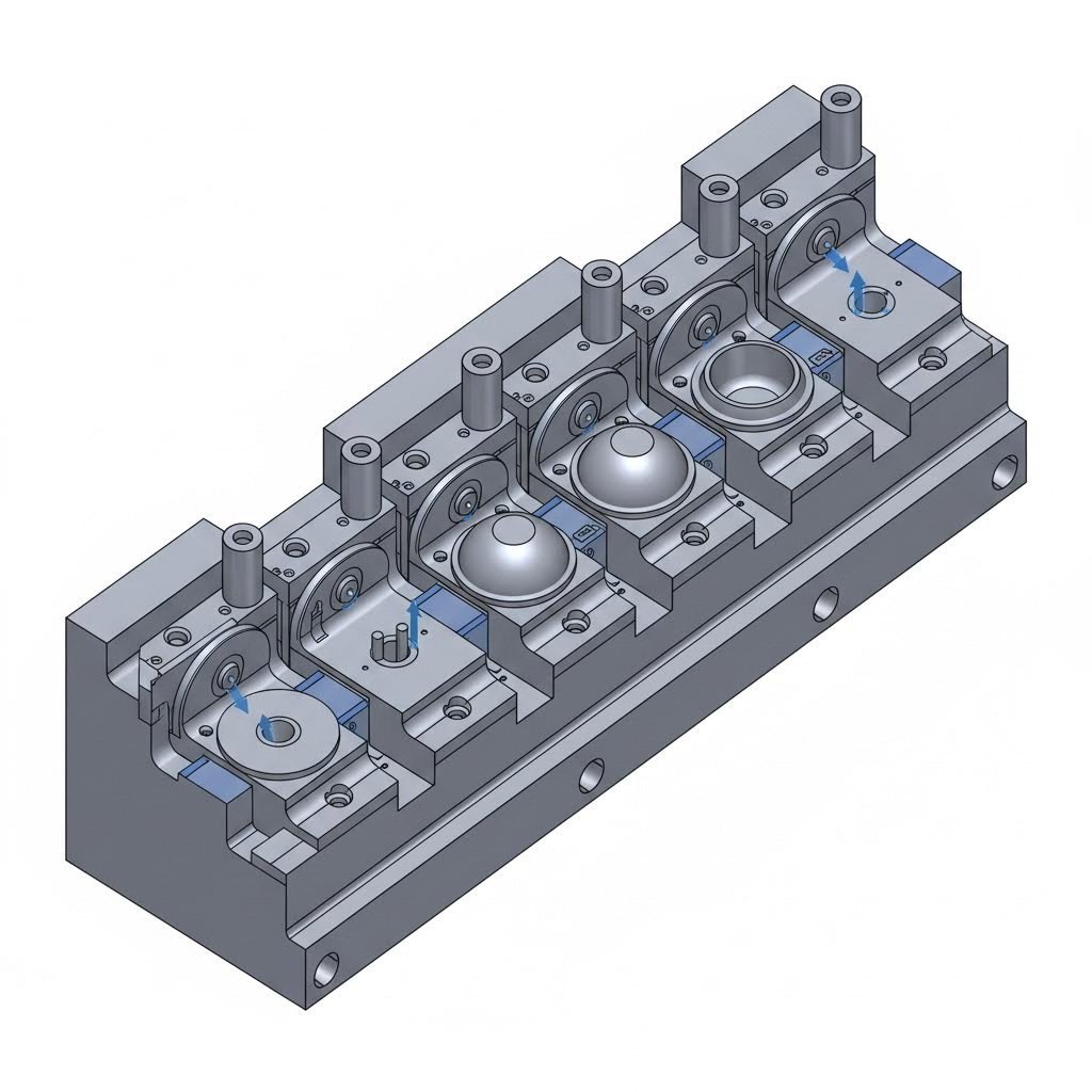
Siz hech qachon ajoyib chiqarilgan detaldan, nuqsonlar bilan to'la detaldan farqini bilmoqchi bo'ldingizmi? Javob — metal chiqarish pressi birinchi marta ishga tushirilishidan oldin sodir bo'ladigan jarayonda yashirilgan. Metal chiqarish uchun moslamalar — ya'ni g'ovaklar, uruvchi qismlar va shakllantiruvchi komponentlar — xom metall varaqni aniq o'lchovdagi detallarga aylantiradi — har bir muvaffaqiyatli ishlab chiqarish operatsiyasining ko'rinmas asosidir.
Moslamalarni chiqarilgan detallaringizning DNK-i sifatida tasavvur qiling. Sizning detallaringizning barcha kesishlari, egilishlari va shakllanishlari shu maxsus moslamalarning sifati va loyihasiga bog'liq. Aniq ishlab chiqilgan moslamalar bo'lmasa, eng zamonaviy metal chiqarish uskunalari ham doimiy natijalar beradigan qimmatbaho uskunaga aylanadi.
Metal chiqarish uchun moslamalar haqiqatan ham nima qiladi
Asosan, metall kesish uskunalari — tekis metall varaqni yakuniy detallarga aylantiruvchi komponentlar tizimini o'z ichiga oladi. Bunga kesish va shakllantirish sirtlarini ta'minlovchi kalıplar to'plami, materialni shakllantirish uchun kuch qo'llaydigan punchlar hamda maxsus operatsiyalarni bajaruvchi kiritalar kiradi. Har bir kesish uskunasi sizning press-ustuvor qurilmangiz bilan sinxron ishlab, nihoyatda aniq operatsiyalarni — masalan, qirqish, teshish, egilish yoki chuqur chizishni amalga oshiradi.
Siz detallarni kesish uskunasi yordamida ishlab chiqarganda, aslida takrorlanadigan ishlab chiqarish retseptini yaratmoqdasiz. Kalıp geometriyasi detalingizning yakuniy shaklini belgilaydi, punch konfiguratsiyasi kuch qo'llash usulini boshqaradi, komponentlar orasidagi bo'shliqlar esa chet sifati va o'lchov aniqligini belgilaydi. Bu elementlarga e'tibor bering — natijada minimal farq bilan minglab bir xil detallar ishlab chiqarishingiz mumkin.
Deyning aniqligi to'g'ridan-to'g'ri chaplangan detallarning sifati va takrorlanuvchanligiga ta'sir qiladi. Yomon ishlab chiqilgan yoki yomon ishlab chiqarilgan asbob-uskunalar noaniqliklarga sabab bo'ladi, chiqindilar darajasini oshiradi va rejasiz to'xtashlarga olib keladi.
Aniq ishlab chiqarishning asosi
Nima uchun asbob-uskunalar shunchalik muhim? Quyidagi haqiqiy ishlab chiqarish natijalarini hisobga oling:
- Detal sifati: Yaxshi ishlab chiqilgan asbob-uskunalar har bir metall chaplangan komponentni aniq o'lchovda va burrsiz chiqaradi, shu sababli unga qo'shimcha yakuniy ishlash talab qilinmaydi va keyingi operatsiyalarga tayyor bo'ladi
- Ишlab чиқиш тезлиги: To'g'ri loyihalangan deylar tsikl vaqtini minimallashtiradi va almashtirish chastotasini kamaytiradi, bu esa sizning ishlab chiqarish quvvatingizni maksimal darajada oshiradi
- Xarajat samaradorligi: Tajribali asbobchi-ustalar tomonidan amalga oshirilgan aqlli dey dizayni material sarfini minimallashtirishga imkon beradi va tezlikda lenta shaklidagi material bilan ishlov berishni qo'llab-quvvatlaydi
- Bir xillik: Aniq asbob-uskunalar detaldan detalga o'zgarishlarni yo'q qiladi, bu esa montaj muammolariga va mijozlarning shikoyatlariga sabab bo'ladi
Avtomobil va aerospace kabi yuqori xavfli sohalarda yetarli vositalarning etishmasligi tufayli sodir bo'ladigan kichik og'ishlar montaj muvaffaqiyatsizliklariga yoki komponentlarning rad etilishiga olib kelishi mumkin. Biroq, to'g'ri chop qilish vositasi ko'pincha ikkinchi darajali ishlash yoki yakuniy ishlov berishni o'chirib qo'yadi — bu sizning ishlab chiqarish dasturingiz bo'ylab ahamiyatli vaqt va xarajatlarni tejash imkonini beradi.
Ushbu asosiy tamoyillarni tushunish sizning aqlli vositalar tanlovi qilishga birinchi qadamdir. Keyingi bo'limlarda siz o'rtacha vositalardan ajoyib ishlab chiqarish natijalarini ajratib turadigan aniq matritsa turlari, material tanlovlari va loyihalash tamoyillarini ochib beradi.
To'g'rilash matritsalari turlari va ularning qo'llanilishi
Endi siz asosiy tamoyillarni tushunganingizdan keyin narsalar qiziqarliroq bo'ladi. Barcha chop qilish matritsalari bir xil emas — va noto'g'ri turdagi matritsa tanlash sizga minglab so'mlik sarflangan material, uzaytirilgan yetkazib berish muddatlari va ishlab chiqarishda qiyinchiliklarga sabab bo'ladi. Ko'pchilik matritsa ishlab chiqaruvchilar sizga aytmaydigan sir nima? Sizning loyihangiz uchun to'g'ri matritsa konfiguratsiyasini tanlash oddiy detallarning geometriyasidan ancha tashqari omillarga bog'liq.
Baholash jarayonida sizning qo'zg'atish operatsiyangiz uchun turli xil asbob-uskunalar , siz to'rtta asosiy matritsa konfiguratsiyasi bilan duch kelasiz: progressiv, murakkab, o'tkazish va kombinatsiya matritsalari. Har biri alohida ishlab chiqarish ehtiyojlarini qondiradi va ularning afzalliklarini tushunish sizga to'g'ridan-to'g'ri foyda olishingizga ta'sir qiladigan qarorlar qabul qilishda yordam beradi.
Yuqori hajmli samaradorlik uchun ketma-ket matritsalar
Bir dona asbob ichiga siqilgan montaj liniyasini tasavvur qiling. Aslida progressiv matritsalarning bajaradigan vazifasi shundaydir. Metal lenta matritsaning bir nechta stansiyalaridan o'tadi; har bir stansiya material har bir press urishida oldinga siljiganda aniq amal — punchlash, egish, shakllantirish yoki kesishni bajaradi.
Progressiv matritsalarni yuqori hajmli ishlab chiqarishning asosiy vositasi qiladigan narsalar quyidagilardir:
- Tezlik: Detallar jarayon davomida tashuvchi lentaga ulanib qoladi, bu esa operatsiyalar o'rtasida qo'lda boshqarishni talab qilmasdan tez sikllash imkonini beradi
- Bir xillik: Bir marta sozlangandan keyin progressiv matritsalar millionlab detallar bo'ylab ajoyib takrorlanuvchanlikni ta'minlaydi
- Samaradorlik: Bir nechta operatsiyalar bir vaqtda amalga oshiriladi, bu esa detalga to'g'ri keladigan mehnat xarajatlarini sezilarli darajada kamaytiradi
- Materiallarning ko'p xil xususiyatlari: Qo'rg'osh, alyuminiy, mis, zanglamaydigan po'lat, latun, hatto titan yoki Inkonel ham progressiv sozlamalar orqali qayta ishlash mumkin
Nima uchun? Progressiv matritsalar metall kesish uchun dastlabki katta investitsiya talab qiladi. Bu ularni ishlab chiqarish hajmi dastlabki matritsa xarajatlarini oqlashi mumkin bo'lganda — odatda 100 000 ta detaldan boshlab — eng arzon variant qiladi. Shuningdek, ular chuqur tortish talab qiladigan detallarga kamroq mos keladi, chunki ishlov berilayotgan detallar jarayon davomida lentaga ulanib turadi.
Murakkab matritsalar: Bitta bosishda aniqlik
Agar sizning ilovangiz aniq o'lchovli, tekis detallarni talab qilsa, murakkab matritsalar ko'pincha eng yaxshi natijalarni beradi. Ketma-ket amallarni bajaradigan progressiv tizimlardan farqli o'laroq, murakkab to'g'ri qilish matritsasi va sozlamalari bir bosishda bir nechta kesish, shakllantirish va punchlash amallarini bajaradi.
Masalan, g'ildiraklar, germatiklar yoki tekis qo'llab-quvvatlovchi plastinkalar. Murakkab matritsalar quyidagi sabablarga ko'ra bu ilovalarga ajoyib mos keladi:
- Yagona chiziq operatsiyasi ajoyib tekislikka ega bo'lgan juda doimiy detallarni ishlab chiqaradi
- Materialdan foydalanish odatda yuqori darajada bo'ladi, shu sababli chiqindi xarajatlari kamayadi
- Oddiy geometriyali detallar uchun qoliplarning narxi progressiv qoliplarga nisbatan pastroq
- Sozlash va konfiguratsiyani o'zgartirish vaqtlari odatda tezroq
Bu yerda cheklov murakkablikdir. Murakkab qoliplar murakkab egilishlar, chuqur shakllar yoki bir nechta ketma-ket operatsiyalarga ega bo'lmagan detallar uchun eng yaxshi ishlaydi. Detallarning loyihasi murakkabroq bo'lganda, boshqa usullarga murojaat qilishingiz kerak.
Murakkab va o'tkazish konfiguratsiyalari orasidan tanlash
O'tkazish qolipli preslanish fundamental jihatdan boshqa yondashuvni talab qiladi. Ishlov berilayotgan detallarni lentaga ulab turish o'rniga, birinchi operatsiya har bir blankani g'ildirakdan ajratadi. Keyin mexanik "barmoqlar" alohida detallarni bir nechta stansiyalarga o'tkazadi, bu stansiyalarning har biri alohida operatsiyalarni bajaradi.
Bu konfiguratsiya progressiv va murakkab qoliplar yetib ololmaydigan vaziyatlarda ajoyib natija beradi:
- Chuqur tortish: Harakatni cheklab turadigan tayanch lenta bo'lmagani uchun o'tkazish qoliplari sezilarli chuqurlikka ega detallarni shakllantirish imkonini beradi
- Murakkab geometriya: Tirnoqli, reybarli va rezba qilish kabi murakkab xususiyatlar amalga oshirish mumkin bo'ladi
- Katta detallar: Progressiv kalıp bilan ishlov berish uchun juda katta bo'lgan komponentlarni samarali ishlab chiqarish mumkin
- Quvur qo'llanilishi: Nayli komponentlarni ishlab chiqarishda ko'pincha transfer kalıplari afzal ko'riladi
Sanoat tahlili ma'lumotlariga ko'ra, transfer kalıp preslanishi murakkab sozlamalar va malakali ishchi kuchi talab qilgani sababli yuqori operatsion xarajatlarga ega. Ayniqsa, murakkab detallar uchun sozlama vaqtida uzunroq muddat ketadi. Biroq, bu usulning moslashuvchanligi uni boshqa konfiguratsiyalar bilan amalga oshirib bo'lmaydigan murakkab dizaynli aniq kalıp va preslanish ilovalari uchun beqiyos qiladi.
Kombinatsiya Kalıplari: Gibriddan foydalanish usuli
Ba'zida sizning loyihangiz biror bir toifaga aniq mos kelmaydi. Birikma shakllantiruvchi matritsalar (kombinatsion die) bir nechta konfiguratsiyalardan elementlarni birlashtiradi — progressiv doira ichida murakkab operatsiyalarni integratsiya qilish yoki odatda alohida uskunalar talab qiladigan kesish va shakllantirish operatsiyalarini birlashtirish. Bu gibrid yechimlar standart yondashuvlar yetarli bo'lmaydigan aniq ishlab chiqarish muammolarini hal qiladi.
Shakllantirish shablonlari turlarini tezkor solishtirish
To'g'ri matritsa turini tanlash bir nechta omillarni muvozanatlashni talab qiladi. Ushbu taqqoslash asosiy qaror qabul qilish me'yoriyliklarini tushuntirib beradi:
| Shablon turi | Eng yaxshi dasturlar | Haqiqiy hajm | Murakkablik darajasi | Odatdagi detallar misollari |
|---|---|---|---|---|
| Qadamdash | Tezlik va barqarorlikni talab qiladigan ko'p operatsiyali detallar | Yuqori hajm (100 mingdan ortiq detallar) | Oddiydan o'rtacha geometriyalarga ega | Elektr kontaktlari, qo'llab-quvvatlovchi qismlar, qisqichlar, terminal qismlari |
| Tarkibdagi | Aniq toleransli oddiy tekis detallar | O'rtacha va yuqori hajm | Past murakkablik | G'ildiraklar, probkalar, tekis blanklar, shimlar |
| Oʻtkazish | Bir nechta operatsiyalarni talab qiladigan katta yoki murakkab detallar | O'rtacha va yuqori hajm | Yuqori murakkablik | Chuqur tortilgan stakanlar, nayli komponentlar, konstruktiv korpuslar |
| Kombinatsiya | Bir nechta matritsa funksiyalarini birlashtiruvchi maxsus qo'llanishlar | Dizaynga qarab farq qiladi | Oʻrtacha va yuqori | O'ziga xos shakllantirish talablari bilan mos keladigan maxsus detallar |
Matritsa tanlovi ishlab chiqarish samaradorligiga qanday ta'sir qiladi
Bu — tajribali ishlab chiqaruvchilar tushunadigan, lekin ochiq holda kamdan-kam hollarda muhokama qilinadigan narsa: matritsa tanlovi bevosita sizning ishlab chiqarish iqtisodiyotingizni belgilaydi. 5000 dona mahsulot uchun progressiv matritsa tanlang — va sizning bir dona mahsulotga to'g'ri keladigan matritsa amortizatsiyasi loyihani iqtisodiy jihatdan maqsadga muvofiq emas qiladi. Murakkab ko'p egilishli komponent uchun kompound matritsa tanlang — va har bir detallarni yakunlash uchun qimmat turadigan qo'shimcha operatsiyalarga ehtiyoj seziladi.
To'g'ri matritsa — metallni chaplash konfiguratsiyasi quyidagilarga mos keladi:
- Ishlab chiqarish hajmi: Yuqori hajmlar qo'llaniladigan uskunalar investitsiyasini o'ziga jalb qiladi
- Qism murakkabligi: Murakkab dizaynlar mos kalıplar imkoniyatlarini talab qiladi
- Material xususiyatlari: Turli xil metallar turli xil kalıp konfiguratsiyalariga turlicha javob beradi
- Sifat talablari: Aniq kalıp va chaplashish qo'llanilishlari kerakli aniqlikni ta'minlash uchun maxsus kalıp turlarini talab qilishi mumkin
- Muddati cheklovlari: Ba'zi kalıp turlari boshqalarga qaraganda tezroq rivojlanish sikllarini taklif qiladi
Bu munosabatlarni tushunish sizga uskunalar hamkorlaringiz bilan ma'lumotli suhbatlashish imkonini beradi — shuningdek, sizning chaplashish operatsiyangiz biznesingizga kerakli natijalarni berishini ta'minlaydi. Kalıp turlari aniqlanganidan keyin keyingi muhim qaror — uskunangiz qanday materiallardan tayyorlanishi to'g'risidir; bu bevosita uskuna yashashi, aniqlik va uzoq muddatli ishlashini ta'sirlaydi.
Uskuna po'latining tanlanishi va materialga oid hisobga olinadigan jihatlari
Siz loyihangiz uchun to'g'ri kalıp konfiguratsiyasini tanlagansiz. Endi endi kalıplar uzun muddat ishlashini ta'minlaydigan yoki erta vaqtida ishdan chiqib ketadigan kalıplarni ajratib turadigan qaror qabul qilish vaqtidir: materialni tanlash. Ko'pchilik kalıp ishlab chiqaruvchilar sizga dastlab aytmasa ham, tanlagan po'lat darajangiz bir millioninchi detaldagi o'lchamlar aniqligidan tortib, ish jarayonida qanchalik tez-tez punchlarni almashtirishingizga qadar hamma narsaga ta'sir qiladi.
Turli xil to'g'ri bosish operatsiyalari kalıp po'latlariga juda farqli talablarni qo'yadi. Qattiqroqlangan punch 0,5 mm lik aluminiydan kesish amaliyoti bilan 3 mm li yuqori mustahkamlikdagi po'latdan teshish amaliyotida duch keladigan kuchlanishlardan butunlay boshqacha. Bu farqlarga tushunish sizga ishlab chiqarish dasturingiz davomida doimiy ravishda ishlaydigan va ishlashni davom ettiradigan kalıplarni belgilash imkonini beradi.
Asbob po'lati darajalari va ularning ishlash xususiyatlari
Arizona shtatidagi qurollar po'lati tarqatuvchilari va maxsus metallurgiya uyalaridan kelgan ta'minotchilar qoliplash (stamping) qo'llanilishlarini muhokama qilganda, to'rtta po'lat kategoriyasi muhokamaga hukmronlik qiladi: D2, A2, S7 va karbid materiallari. Har biri ishlov berilayotgan detallar materialiga, ishlab chiqarish hajmiga va aniqlik talablariga qarab o'ziga xos afzalliklarga ega.
D2 O'qish Po'lati d2 po'lati — po'latdan qoliplash vositalarining ishchi ot (ishonchli, ishlaydigan) sifatida obro' qozongan. Taxminan 12% xrom kontsentratsiyasiga ega bo'lgan D2 ajoyib sirpanishga chidamlilik va kesish chetlarini saqlash qobiliyatini ta'minlaydi. Shuningdek, Dayton Lamina texnik tadqiqotlari ga ko'ra, eritma qotganda xrom kabi alloylar uglerod bilan birlashib karbidlar hosil qiladi; bu esa abraziv va adgeziv sirpanish zararlariga qarshilik ko'rsatadigan zarrachalarni vujudga keltiradi. Biroq, shu yuqori alloy tarkibi D2 ni boshqa variantlarga nisbatan mo'rtroq qiladi — bu esa urilish yoki cho'ntaklanish yuklamalari bilan bog'liq qo'llanilishlar uchun muhim hisoblanadi.
A2 Asbobli Po'lat boshqa muvozanat taklif etadi. D2 ga nisbatan bir qancha izdoshlik chidamliligini yo'qotib, A2 materiali termik ishlov berish paytida yuqori qattiqlik va o'lchovlar doimiylikka ega bo'ladi. Bu kesish chetining maksimal umr ko'rishi ahamiyatli bo'lmagan, lekin aniq o'lchovlar saqlash muhim bo'lgan aniqlikli to'g'ri bosish (stamping) qo'llanilishlari uchun idealdir. Ko'p sonli ishlab chiqaruvchilar o'rtacha hajmdagi ishlab chiqarish uchun, shuningdek, ayrim vaqtlarda qayta o'tkirlash qabul qilinadigan po'lat asbob-uskunalar uchun A2 materialini tanlaydi.
S7 asbob po'toli s7 materiali qattiqlik spektrining qattiqroq (mustahkamroq) qismiga mos keladi. Sizning qo'llanilishingizda zarba yuklamalari mavjud bo'lsa, S7 materiali D-seriyali materiallarga qaraganda chip (cho'ntak) hosil bo'lishi va troshlanishga chidamliligi yuqori bo'ladi. Masalan, og'ir qirqish (blanking) operatsiyalari yoki kesish chetiga har bir press urilishi katta ta'sir ko'rsatadigan qalin materiallarni to'g'ri bosish (stamping) jarayonlarini hisobga oling. Narx? S7 materiali D2 ga qaraganda tezroq ishlamoqda, shuning uchun sizga tez-tez texnik xizmat ko'rsatish kerak bo'ladi.
Karbidli asbob-uskunalar (K10, K20, K30 kabi volfram karbidi darajalari) istalgan po'lat asbob materialidan ancha yuqori qattiqlikni ta'minlaydi. Tarmoq bo'yicha tahlil karbidning ajoyib qattiqlikka ega ekanligini tasdiqlaydi, bu uning aniq kesish yuzlari va kesish segmentlari uchun ideal bo'lishiga sabab bo'ladi. Cheklov nima? Karbidlar shishiluvchan va odatda butun die tarkibiy qismlari uchun emas, balki mustahkamroq po'lat tanada joylashgan kiritma sifatida ishlatiladi.
Ishlashni Belgilovchi Asosiy Xususiyatlar
Sizning bosib chiqarish operatsiyangiz uchun asbob po'latlarini baholaganda, to'rtta xususiyat haqiqiy dunyodagi ishlashni aniqlaydi:
- Qattiqlik (HRC ballari): Rockwell C shkalasi bo'yicha o'lchanadi; qattiqlik deformatsiyaga qarshilik darajasini ko'rsatadi. D2 odatda 58–62 HRC ni, A2 esa 57–62 HRC ni, S7 esa 54–58 HRC ni amalga oshiradi. Yuqori qattiqlik odatda yaxshiroq sirpanishga chidamlilikni anglatadi, lekin mustahkamlik pasayadi.
- Qo'lga olinish: Po'latning urilish ta'sirida sindirilish, chip qilinish yoki troshlanishga qarshilik qilish qobiliyati. Bu sohada S7 yetakchilik qiladi, undan keyin A2 keladi, D2 esa oxirida turadi. Metallurgik tadqiqotlarga ko'ra, asbob po'latining mustahkamligi qo'shimcha elementlar miqdori ortishi bilan pasayadi.
- Ishlaydigan suy ergashligi: Qanday qadar yaxshi po'lat ishlov beriladigan materiallar, boshqa asboblar yoki qo'pollik va g'ovak kabi zarralarga nisbatan sirpanishga qarshilik ko'rsatadi. Qotishma tarkibining oshishi odatda po'latda karbidlarning soni ko'paygani uchun yaxshiroq sirpanishga qarshilik ko'rsatishni anglatadi
- Ishlov berish: Po'latni sertlashtirishdan oldin qanday qadar osongina ishlov berish mumkinligi. Bu asbob-uskunalar yetkazib berish muddati va o'zgartirish xarajatlariga ta'sir qiladi. A2 D2 ga qaraganda osongina ishlov beriladi, chunki D2 issiqlik bilan qayta ishlangandan keyin ishlov berish juda qiyinlashadi
Asbob-uskunalar materiallarini ishlab chiqarish talablariga moslashtirish
Murakkab tuyuladi? Tajribali asbobsozlar amaliyotda material tanlashni qanday amalga oshirishadi:
Presslashda alyuminiy va alyuminiy qotishmalari , muammo qattiklik emas — balki yopishuvdir. Alyuminiy asbob-uskunalar yuzasiga yopishib qoladi, bu esa ishqalanishni oshiradi va detallarning sifatini pasaytiradi. Tavsiya etilgan materiallar — TiCN kabi PVD qoplamali A2 yoki M2 po'latlaridir, chunki ular ishqalanish koeffitsientini kamaytiradi.
Uchun yuqori mustahkamlikdagi po'latlar (DP, CP darajalari)da talablar oshib boradi. Bu materiallarni yuqori bosim ostida chiqarish uchun D2, PM M4 yoki ASP 23 changli poʻllar kerak boʻladi. Sirt qoplamalari majburiy, yaʼni ixtiyoriy emas.
Bilan ishlashda ultra-yuqori mustahkamlikdagi poʻllar (TRIP, PHS, martensit darajalari)da anʼanaviy poʻllar tezda ishdan chiqadi. Qabul qilinadigan uskuna xizmat muddati uchun ASP 30 yoki CPM 10V kabi changli metallurgiya poʻllari, karbidli qismlar yoki qattiq sirtlarga ega, lekin mustahkam yadrolarga ega gibrid uskunalar kerak boʻladi.
Material tanlovi oʻlchamlarning aniqligiga qanday taʼsir qiladi
Raqobatchilar deyarli hech qachon muhokama qilmaydigan narsa shundaki: siz tanlagan poʻllar sizning chiqarilgan detallaringizning uzun ishlab chiqarish davomida oʻlchamlar doirasini qanchalik yaxshi saqlashi bilan bevosita bogʻliq. Siqilish mustahkamligini hisobga oling — bu uskunaning shakl oʻzgartirmasdan oldin bardosh bera oladigan maksimal yukni oʻlchovidir. Texnik tadqiqotlarga koʻra, molibden va volfram kabi qotishma elementlari siqilish mustahkamligiga hissa qoʻshadi, shuningdek, yuqori qattiqlik ham bu xususiyatni yaxshilaydi.
Qattiq punch yuk ostida deformatsiyaga uchraganda, sizning detallaringiz o'lchamlari siljib ketadi. Bu jarayon asta-sekin sodir bo'ladi — dastlab ko'pincha sezilmaydi — va keyin sifat tekshiruvlari tolereansi chegarasidan tashqari sharoitlarni aniqlab boshlaydi. Sizning ma'lum bir qo'llanilishingiz uchun yetarli siqilish chidamliligiga ega bo'lgan asbob po'latini tanlash bu o'lcham siljishini oldini oladi.
To'g'ri issiqlik ishlov berish ham shu darajada muhimdir. Har bir asbob po'lati darajasi uchun aniq issiqlik ishlov berish qo'llanmasi mavjud bo'lib, uni bosib chiqarish qo'llanilishlari uchun optimal natijalarga erishish uchun qat'iy amal qilish kerak — bu kesish vositalari uchun qo'llanilishlardan jiddiy farq qiladi. Issiqlik ishlov berish jarayoni po'latning mikrostrukturasini o'zgartirib, sizning qo'llanilishingiz talab qiladigan qattiqlik va chidamlilik muvozanatini ta'minlaydi.
Bu material omillarini tushunish sizga xizmat muddati davomida doimiy sifatni ta'minlaydigan asbob-uskunalarni belgilash imkonini beradi. Biroq hatto eng yaxshi po'lat ham ishlash uchun to'g'ri texnik xizmat ko'rsatishni talab qiladi — bu esa bizni tez-tez e'tibordan chetda qolinadigan asbob-uskuna hayot sikli boshqaruvi mavzusiga olib keladi.
Samarali chiziqqa qo'yish uskunalari uchun dizayn tamoyillari
Siz to'g'ri matritsa turini tanlagansiz va sifatli matritsa po'latlarini belgilagansiz. Endi funksional uskunalar bilan haqiqatan ham ajoyib ishlab chiqarish samaradorligini ajratib turuvchi muhandislik faniga kelmoqdamiz: dizayn parametrlari. Quyida tajribali metall chiziqqa qo'yish matritsalarini ishlab chiqaruvchilari asosiy o'quv qo'llanmalarida deyarli hech qachon ko'rinmaydigan narsalarni tushunadilar — sizning uskunangizdagi geometrik munosabatlar siz tomonidan ishlab chiqariladigan tozalik, o'lchov jihatidan aniq detallarni yoki ishlab chiqarish vaqtini burrlar, troshinlar va o'lchovlarning siljishi bilan kurashishga sarflashni aniqlaydi.
Matritsa dizaynini haqiqiy oqibatlarga ega bo'lgan fizika masalasi sifatida tasavvur qiling. Siz belgilagan har bir bo'shliq o'lchovi, har bir urish burchagi, har bir radius ishlov berilayotgan materialda kuchlanish namoyon etadi. Bu munosabatlarni to'g'ri belgilasangiz, metall sizning istagan shaklingizga bashorat qilish mumkin bo'lgan tarzda oqadi. Agar ular noto'g'ri belgilansa, har bir rad etilgan mahsulot qutisida bu xatoliklarni ko'rasiz.
Ayrim nuqsonlarni oldini oluvchi bo'shliq hisoblashlari
Matritsa bo'shlig'i — teshuvchi kesish chetining va matritsa ochilishining orasidagi bo'shliq — metall qo'zg'atish uskunalarini loyihalashda eng muhim parametr hisoblanadi. Buning haqida Mate Precision Technologies' texnik hujjatlari shunday deyiladi: to'g'ri matritsa bo'shlig'i bevosita uskuna xizmat ko'rsatish muddati, qopqoqni olib tashlash samaradorligi, burrlar balandligi, teshik sifati va teshish kuchi talablari ta'sirini ko'rsatadi.
Teshuvchi harakatlanayotganda mikroskopik darajada quyidagilar sodir bo'ladi: teshuvchi materialga kirib borayotganda, kesish yorilishlari teshuvchi chetidan ham, matritsa chetidan ham tarqaladi. Bo'shlik to'g'ri bo'lsa, bu yorilish chiziqlari tozalik bilan bir-biriga ulanadi va minimal burrli, doimiy qirrali detallar hosil qiladi. Bo'shlik noto'g'ri bo'lsa, barcha narsa buziladi.
Juda tor bo'shlik materialning tabiiy ravishda yorilishiga yetarli joy yo'qligi sababli ikkinchi darajali kesish yorilishlarini vujudga keltiradi. Oqibatlari ketma-ket keladi:
- Teshish kuchi keskin oshadi, bu esa uskunaning tezroq ishdan chiqishiga sabab bo'ladi
- Ortib ketgan issiqlik hosil bo'ladi, bu kesuvchi qirralarning yumshashiga sabab bo'ladi
- Material teshuvchi sirtiga yopishib qoladi va galling (sirtning yopishib qolishi) sodir bo'ladi
- Asbobning ishlash muddati optimal aralashmadan solishtirganda 30–50% ga kamayadi
- Detallarda ikkinchi tozalash jarayoniga qarshilik ko'rsatadigan ish qilish natijasida qattiqroq bo'lgan chetlar hosil bo'ladi
Ortiqcha bo'shliq nazorat ostidagi kesishni yo'q qiladi va jarayonni nazoratsiz yirtishga aylantiradi:
- Teshikning uruvchi tomonida katta aylanma chet hosil bo'ladi
- Matritsa tomonidagi chetlarda chet balandligi va qalinligining oshishi
- O'lchami kattalashgan chiplar chiqarilishga qarshilik ko'rsatgani uchun chiplar tortilish muammolari
- Kesish paytida material shakli o'zgarib ketgani sababli o'lchamlarning noaniqlikka uchrashi
- Yomon teshik sifati: g'ayrioddiy, notekis sindirish zonalariga ega
Demak, to'g'ri aralashma qancha? Bu sizning material turigiz va qalinligingizga bog'liq. Sanoat qo'llanmalarida boshlang'ich nuqtalar keltirilgan:
| Material turi | Kalinlik diapazoni | Umumiy aralashma (qalinlikning %) |
|---|---|---|
| Alyuminiy | 0,098" (2,50 mm) dan kam | 15% |
| Alyuminiy | 0,098" dan 0,197" gacha (2,50–5,00 mm) | 20% |
| Yumshoq po'lat | 0,118" (3,00 mm) dan kam | 20% |
| Yumshoq po'lat | 0,118" dan 0,237" gacha (3,00–6,00 mm) | 25% |
| Zanglamaydigan po'lat | 0,059" (1,50 mm) dan kam | 20% |
| Zanglamaydigan po'lat | 0,059" dan 0,157" gacha (1,50–4,00 mm) | 25-30% |
Bu foizlar — jami bo'shliqni ifodalaydi — shakllantiruvchi teshuvchi ustunining ikkala tomonidagi bo'shliqlar yig'indisini. Tajribali metall shakllantirish loyihalash muhandislari ushbu boshlang'ich qiymatlarni aniq material darajalari, sirtni yakunlash talablari va ishlab chiqarish hajmi kutishlari asosida sozlaydilar.
Tozalikli kesish va shakllantirish uchun geometriyani optimallashtirish
Bo'shliqdan tashqari, teshuvchi va kalip geometriyasi detallarning sifatiga hamda qurollarning xizmat ko'rsatish muddatiga bevosita ta'sir qiladi. Ushbu elementlarning ishlov berilayotgan material bilan qanday o'zaro ta'sirlashuvini tushunish nuqsonlarni ular vujudga kelishidan oldin bartaraf etadi.
Chuqurlikdan material qalinligiga nisbatlar fizik jihatdan erishiladigan chegaralarni belgilaydi. Texnik ko'rsatmalar ko'rsatishicha, aluminiyda standart asbob-uskunalar material qalinligining 0,75 barobariga teng diametrli teshiklar ochadi. Yumshoq po'latda bu nisbat 1:1 ga oshadi. Ruxsatsiz po'lat uchun esa punch diametri material qalinligidan kamida ikki barobar katta bo'lishi kerak. Bu chegaralardan o'tish punchning og'ishiga, tezroq yeyilishga va oxir-oqibat sindirilishiga sabab bo'ladi.
Burchak radiuslari e'tibor bilan muomala qilishni talab qiladi. O'tkir burchaklar kuchlanishni konsentratsiyalashtiradi, to'g'ri chiziqlarga qaraganda tezroq yeyiladi va trostikka moyil xususiyatlarga ega detallar ishlab chiqaradi. 45 gradusdan kam burchaklarga 0,010" (0,25 mm) dan kam bo'lmasa bo'lmaydigan minimal radiuslar qo'shilishi tez yeyilishni oldini oladi va detalning mustahkamligini oshiradi. Metallni bosib shakllantirish va egish sohalari uchun keng radiuslar shuningdek, egish operatsiyalari paytida materialning silliq oqishiga imkon beradi.
Sovuq shakllantirish jarayonining dinamikasini tushunish
Sovuq shakllantirish — metallarni issiqlikdan emas, balki kuch orqali xonada haroratda shakllantirish — yaxshi chiziq qilish dizaynini aniqlaydigan bashorat qilinadigan jismoniy qonunlarga amal qiladi. Buning haqida Luvata muhandislik tavsiyalari ga ko'ra, ushbu jarayon metallardagi dona oqimini saqlab qoladi va mustahkamlik hamda chidamlilik xususiyatlariga ega detallarni ishlab chiqaradi.
Biroq, sovuq shakllantirish jarayonining o'ziga xos talablari mavjud:
- Simmetriya muhim ahamiyatga ega: O'q va pinalar kabi aylanma elementlar nisbatan noaniq geometriyalarga qaraganda ishonchliroq shakllanadi
- Postepenni o'tishlar eng yaxshi natija beradi: Keskin burchaklar o'rniga filletlar, keskin qadam o'rniga asta-sekin toraytirish materialning silliq oqishiga imkon beradi va asbob-uskunalarga zarar yetkazmaydi
- Devor qalinligi chegaralangan: Har bir material uchun devor qalinligining minimal va maksimal qiymatlari mavjud; ulardan tashqari qilinganda material yorilishi yoki noaniq oqish sodir bo'ladi
- Donaning yo'nalishi mustahkamlikka ta'sir qiladi: Yukni ushlab turuvchi elementlar shakllantirish jarayonida hosil bo'lgan don oqimi naqshlariga mos kelishi kerak
Egish va shakllantirishni o'z ichiga olgan metall kesish usullari uchun materialning cho'ziluvchanligi muhim ahamiyatga ega. Yumshoq po'lat yaxshi sovutda shakllanadi, chunki u ajoyib cho'ziluvchanlikka ega va varaq mustahkamligi bilan birga ishlaydi. Ruxsatsiz po'lat ham ishlatiladi, lekin unda ko'proq kuch talab qilinadi. Alyuminiy osongina shakllanadi, lekin uning past cho'zilish chidamliligi tufayli dizayn bo'yicha ba'zi moslamalar talab qilinishi mumkin.
Optimal natijalar uchun dizayn ketma-ketligi
Professional asbob-uskuna dizayni har bir parametrni mantiqiy tartibda hisobga oladigan tuzilgan ketma-ketlikni amalga oshiradi. Bu ketma-ketlikni amalga oshirish qimmatbaho qayta dizaynlarni oldini oladi va barcha omillarga mos darajada e'tibor berilishini ta'minlaydi:
- Material tahlili: Ishlov beriladigan detallarning kesish chidamliligi, cho'ziluvchanligi, qalinlik toleranslari va don yo'nalishini hujjatlarga tushiring. Bu xususiyatlar keyingi barcha qarorlar uchun chegaralarni belgilaydi
- Elementlarni baholash: Muhim o'lchamlarni no'muhim xususiyatlardan ajrating. Faqat funksional talablarga mos keladigan joylarda qattiq to'g'rilik chegaralarini qo'llang — barcha o'lchamlarga qattiq chegaralar belgilash faqat qiymatsiz qo'shimcha xarajatlarga sabab bo'ladi
- Bo'shliq spetsifikatsiyasi: O'rnatilgan yo'riqnomalarga asoslanib, material turi va qalinligiga qarab kalibrlar orasidagi bo'shliqlarni hisoblang, so'ngra aniq sifat talablariga mos ravishda sozlang
- Geometriya ta'rifi: Chuqurlik burchaklari, chiqish burchaklari va yuzaki finishlarni hamda punch va kalibrlarning profilini ko'rsating. Stress konsentratsiyasiga sabab bo'ladigan keskin burchaklar va sudden qalinlik o'zgarishlaridan saqlaning
- Kuch hisobi: Press quvvati dizayn talablarini qondirishini ta'minlash uchun kerakli tonnajni aniqlang. Qo'llanilish natijasida vositalarning o'tkirligi pasayishi tufayli talab qilinadigan kuchning vaqt o'tishi bilan oshishini hisobga olgan holda xavfsizlik marginlarini kiritng
- Lenta tuzilishini optimallashtirish: Progressiv kalibrlar uchun materialdan foydalanishni stansiya orasidagi masofa va pilot talablari bilan muvozanatlash maqsadida strip tartibini loyihalang
- Simulyatsiya tekshiruvi: Po'latni kesishdan oldin potentsial elastik qaytish muammolari, material oqish muammolari yoki stress konsentratsiyalarini aniqlash uchun FEA dasturiy ta'minotidan foydalangan holda dizaynlarni tasdiqlang
Odatda uchraydigan sifat muammolarini oldini olish
To'g'ri loyihalash — yomon muhandislik qilingan asbob-uskunalarda kuzatiladigan nuqsonlarni oldindan bashorat qiladi va ularni oldini oladi. Quyida loyiha qarorlari bilan aniq sifat natijalari o'rtasidagi bog'liqlik ko'rsatilgan:
Ortiqcha burrlar odatda noto'g'ri bo'shliq, botgan asboblar yoki noto'g'ri joylashtirilgan stansiyalarga borib taqaladi. Loyiha yechimlari: sizning materialingiz uchun mos bo'shliqlarni belgilash, to'rtburchak kalıplarga bir xil bo'shliqlarni saqlash uchun "bo'shliq burchaklarini" qo'llash va qayta sharpanishni osonlashtirish uchun texnik xizmat ko'rsatishga kirish imkonini beruvchi tashkil etishni nazarda tutish.
Detal singan ko'pincha keskin burchaklar, yetarli egilish radiuslarining yetishmasligi yoki materialning plastiklik chegarasidan oshib ketadigan shakllantirish operatsiyalari tufayli vujudga keladi. Barcha o'tish nuqtalarida keng radiuslarni qo'llang, muhim egilishlarni mumkin bo'lganda dona yo'nalishiga perpendikulyar qilib yo'naltiring va qiyin operatsiyalar uchun shakllantirish moylarini belgilang.
O'lchamli siljish ishlab chiqarishda ortiqcha ishlatilish vosita yeyilishini, issiqlik kengayishini yoki materialni etarli darajada qisib turishning yetishmasligini ko'rsatadi. Bu muammolarga yechim sifatida sizning hajmingiz uchun yetarli yeyilishga chidamli puxta po'latdan tayyorlangan vositalarni belgilash, yuqori tezlikda ishlash uchun sovutish kanallarini kiritish va har bir operatsiya ketma-ketligi davomida materialni aniq joylashtirishni ta'minlash kabi loyiha xususiyatlari ishlatiladi.
Ga binoan barcha vositalarga oid to'liq tadqiqot doimiy, ishonchli chop etish natijalariga erishish uchun materialning xatti-harakati bilan boshqaruvchi ilmiy tamoyillarni hamda uni boshqaruvchi muhandislik prinsiplarini tushunish talab etiladi. Yetuk vosita loyichalari barcha ushbu parametrlarni bir vaqtda muvozanatga keltiradi — chunki bir sohada o'zgarish butun tizimga ta'sir qiladi.
Qattiq loyiha tamoyillari o'rnatilgandan keyin vositalarning muvaffaqiyati uchun quyidagi muhim omil — bu aniqlikni vaqt o'tishi bilan saqlab turishdir. To'g'ri hayot davri boshqaruvi sizning investitsiyangiz sifatli detallarni ishlab chiqarishda davom etishini yoki asta-sekin ishlab chiqarish muammolarining manbasiga aylanishini hal qiladi.
Texnologik jihozlar ta'mirlash va hayot davri boshqaruvi
Siz sifatli texnologik jihozlar — to'g'ri loyihalangan va yuqori sifatli materiallardan yasalgan — uchun investitsiya qildingiz. Endi ko'pchilik kalıp ishlab chiqaruvchilari aytishni istamaydigan noqulay haqiqat: hatto eng yaxshi chiziqqa (stamping) kalıplari ham tizimli ta'mirlashsiz qimmatbaho metall qoldiqlarga aylanadi. Millionlab bir xil detallarni ishlab chiqaradigan va ishlab chiqarishda muammolarga sabab bo'ladigan texnologik jihozlar o'rtasidagi farq ko'pincha pressda ishlashlar orasida nima sodir bo'lishiga bog'liq.
Texnologik jihozlar ta'mirlashini avtomobil xizmat ko'rsatish kabi o'ylang. Agar siz uzun muddat moy almashtirmasangiz, aniq loyihalangan dvigatel vahshiy tarzda ishdan chiqadi. Xuddi shu qoida sizning chiziqqa (stamping) kalıplingizga ham tegishli — faqat bu holatda oqibatlari: rad etilgan detallar, yetkazib berishlarning kechikishi va oldini olish maqsadida amalga oshiriladigan ta'mirlashga sarflangan mablag'lardan bir necha baravar ko'proq pul talab qiladigan favqulodda ta'mirlash xarajatlari.
Faol ta'mirlash orqali texnologik jihozlar yaroqlilik muddatini uzaytirish
Oldini olish usulidagi texnik xizmat ko'rsatish asbob-uskunalarni qiymati pasayib borayotgan aktivdan ishonchli ishlab chiqarish resursiga aylantiradi. Sanoat tadqiqotlariga ko'ra, yaxshi xizmat ko'rsatilgan jihozlar kutilmagan uzilishlarni kamaytiradi va qimmatga tushadigan ishlab chiqarish to'xtatilishlarini oldini oladi. Asosiy jihat — muammolarni ish jarayonida emas, balki rejalashtirilgan to'xtatish vaqtida kichik nuqtalarda hal etishdir.
Amaliyotda samarali texnik xizmat ko'rsatish dasturi qanday ko'rinishda bo'ladi? Quyida sifatli asbob-uskuna va shakllantirish operatsiyalari qo'llaydigan choralar keltirilgan:
- Vizual tekshiruvlar (har bir ishlab chiqarish jarayonidan keyin): Kesish chetlarini chip, trog'lar yoki nooddiy yopishuv belgilari uchun tekshiring. Ishlaydigan sirtlarni galling, iz qoldirish yoki materialning qoplami bilan qoplanishini tekshiring — bu moylash muammolarini ko'rsatadi.
- O'tkirlash oraliqlari (urilishlar soniga asoslanadi): O'tkirlash rejalarini taqvim vaqtiga emas, balki haqiqiy ishlab chiqarish soniga bog'lang. Aksariyat operatsiyalar asboblar uchun urilishlar sonini kuzatib boradi va oldindan belgilangan chegaralarga yetganda texnik xizmat ko'rsatishni boshlaydi — odatda kesish chetining sifatga ta'siri boshlanguncha.
- Moslikni tekshirish (haftalik yoki ikki haftalik): O'lchash va shakl o'zgarishlar paydo bo'lishidan oldin moslikning siljishini aniqlash uchun matritsaning mosligini hujjatga tushiring. Kichik moslik buzilishlari vaqt o'tishi bilan kuchayib boradi va natijada noaniq ishlash va detallarning nuqsonli bo'lishiga sabab bo'ladi.
- Suyuqlik bilan yoritishni tekshirish (ishlab chiqarish davomida har kuni): Barcha muhim sirtlarga mos yoritish moddasining yetkazilishini tasdiqlang. Yetarli bo'lmagan yoritish ishlashni eksponent ravishda tezlashtiradi va kesuvchi qirralarni yumshatishi mumkin bo'lgan issiqlik hosil qiladi.
- Bo'shliqni o'lchash (oylik yoki choraklik): Detallarning aylanish joylaridagi bo'shliqlarni kuzatib boring. Asboblar ishlash jarayonida bo'shliqlar kengayadi — natijada qirralarda burrlar va sifat muammolari vujudga keladi.
Yuzaki tekshiruvlardan tashqari, ilg'or usullar ko'rinmas muammolarni aniqlash imkonini beradi. Texnik tahlil matritsada to'liq noto'g'ri ishlashga sabab bo'lishi mumkin bo'lgan, ko'rinmas qatlamlardagi nuqsonlarni aniqlash uchun ultratovushli sinov va magnit zarrachali tekshiruvni tavsiya qiladi. Bu usullar ayniqsa, kutilmagan matritsa singanida butun ishlab chiqarish liniyalarini to'xtatadigan yuqori hajmli ishlab chiqarishda muhim ahamiyatga ega.
Asboblar yeyilishining dastlabki ogohlantiruvchi belgilari
Tajribali operatorlar sifat hisobotlari tasdiqlamaguncha muammolarni aniqlashga deyarli intuitsiya asosida qobiliyatga ega bo'ladilar. Quyidagilarga e'tibor bering:
- Chiqindining balandligi oshishi: O'rnatilgan chegaralardan tashqari o'sayotgan chiqindilar kesish uchlari botayotganini yoki tozaliklar spetsifikatsiyadan tashqari kengayganini ko'rsatadi
- O'lcham og'ishlari: Detallarning asta-sekin tolereansiya chegaralariga intilishi ketma-ket yeyilishni va qo'llanish talab qiladigan jarayonni ko'rsatadi
- Sirtning holati o'zgarishi: Xizmat ko'rsatishda yoki shakllantirish sirtlarida materialning qoplamasi sababli xizmat ko'rsatish muammolari yoki materialning qoplamasi sababli xizmat ko'rsatish muammolari yoki materialning qoplamasi sababli xizmat ko'rsatish muammolari yoki materialning qoplamasi sababli xizmat ko'rsatish muammolari yoki materialning qoplamasi sababli xizmat ko'rsatish muammolari yoki materialning qoplamasi sababli xizmat ko'rsatish muammolari yoki materialning qoplamasi sababli xizmat ko'rsatish muammolari yoki materialning qoplamasi sababli xizmat ko'rsatish muammolari yoki materialning qoplamasi sababli xizmat ko'rsatish muammolari yoki materialning qoplamasi sababli xizmat ko'rsatish muammolari yoki materialning qoplamasi sababli xizmat ko'rsatish muammolari yoki materialning qoplamasi sababli xizmat ko'rsatish muammolari yoki materialning qoplamasi sababli xizmat ko'rsatish muammolari yoki materialning qoplamasi sababli xizmat ko'rsatish muammolari yoki materialning qoplamasi sababli xizmat ko'rsatish muammolari yoki materialning qoplamasi sababli xizmat ko'rsatish muammolari yoki materialning qoplamasi sababli xizmat ko'rsatish muammolari yoki materialning qoplamasi sababli xizmat ko'rsatish muammolari yoki materialning qoplamasi sababli xizmat ko'rsatish muammolari yoki materialning qoplamasi sababli xizmat ko'rsatish muammolari yoki materialning qoplamasi sababli xizmat ko'rsatish muammolari yoki materialning qoplamasi sababli xizmat ko'rsatish muammolari yoki materialning qoplamasi sababli xiz......
- Press kuchining oshishi: Bir xil operatsiya uchun tonnaj ko'rsatkichlarining oshishi asboblar botayotganini va materialni kesish yoki shakllantirish uchun ko'proq kuch talab qilinayotganini ko'rsatadi
- G'ayrioddiy tovushlar: Chaplashish jarayonida akustik imzo o'zgarishlari — g'irillash, chiqqich ovozi yoki nojuziy urilishlar — ko'pincha sifat muammolarining ko'rinadigan belgilari oldidan keladi
- Qoldiqlar xulqati: Qoldiqlarning qolishi, og'ishishi yoki noaniq chiqarilishi matritsa burmasi yoki kalip bo'shlig'i muammolarini ko'rsatadi
Muhim tushuncha shundaki, ushbu ogohlantiruvchi belgilarga darhol chora ko'rishingiz kerak. Sifati pasaygan asbob-uskunalar bilan ishlab chiqishni davom ettirish faqatgina chiqindilarni hosil qilmaydi — balki vaqtida texnik xizmat ko'rsatilmasa saqlanib qolishi mumkin bo'lgan komponentlarning yeyilishini tezlashtiradi.
Asbob-uskunalar zaxirasini boshqarish bo'yicha eng yaxshi amaliyotlar
Aytaylik, sizning muhim kalipingizga almashtirish uchun burma kerakligini aniqladingiz — lekin siz uning mavjud deb o'ylagan ehtiyot qismini boshqa korxonada yoki hujjatlarga kiritilmagan holda o'nta oy avval iste'mol qilinganligini aniqlaysiz. Yomon asbob-uskunalar zaxirasini boshqarish aynan shu vaziyatlarga sabab bo'ladi va kichik texnik xizmat ko'rsatish talablari katta ishlab chiqarish kechikishlariga aylanadi.
Ga binoan zaxira boshqaruvi bo'yicha tadqiqot — samarali asboblar ombori boshqaruvi aniq foydalar beradi: asboblar bilan bog'liq to'xtash vaqtlari kamayadi, xarid qilish xarajatlari pasayadi va resurslarni taqsimlash yaxshilanadi. Asos bir nechta o'zaro bog'langan amaliyotlardan iborat:
- To'liq kataloglash: Har bir asbob va ehtiyot qismni noyob identifikatorlar, joriy holati, joylashuvi va foydalanish tarixi bilan hujjatlashtiring. Bu baza barcha boshqa jarayonlarga asos bo'ladi
- Haqiqiy vaqtdagi kuzatish: Asboblar harakatini kuzatish uchun shtrix-kod yoki RFID tizimlarini joriy eting. Asboblar ombori dasturiy ta'minoti sizga nima mavjud, nima ishlatilayotgan va nima texnik xizmat ko'rsatish uchun chiqarilganligi haqida darhol ko'rinish beradi
- Texnik xizmat ko'rsatish bilan integratsiya: Zaxira tizimlarini texnik xizmat ko'rsatish jadvallari bilan bog'lang, shunda qayta o'tkazish, tiklash va almashtirish amaliyotlari avtomatik ravishda yozuvlarga kiritilsin
- Qayta buyurtiraish triggerlari: Ehtiyot qismlar zaxirasi minimal chegaradan pastga tushganda ogohlantirishlarni sozlang. Avtomatlashtirilgan bildirishnomalar «teshuvchilar tugab ketdi» kabi ishlab chiqarishni to'xtatadigan favqulodda vaziyatlarni oldini oladi
- Foydalanish analitikasi: Ehtiyot qismlar zaxirasi darajasini optimallashtirish uchun iste'mol namunalarni kuzatib boring. Ma'lumotlar qaysi komponentlar tezroq ishlashini va qayerda qo'shimcha investitsiyalar ishlab chiqarishni eng yaxshi himoya qilishini ko'rsatadi.
Zamonaviy asboblar saqlash dasturiy ta'minoti platformalari bu imkoniyatlarga bulutli ulanish, ish joyida yangilanishlar uchun mobil ilovalar hamda ERP tizimlari bilan integratsiya qilish orqali kengaytiradi. Bir nechta korxonalar yoki ishlab chiqarish liniyalari bo'ylab asbob-uskunalar boshqaruvi bilan shug'ullanadigan operatsiyalar uchun markazlashtirilgan ko'rinishlik ishlab chiqarishni kechiktiruvchi zaxira 'ko'rinmas maydonlarini' oldini oladi.
Texnik xizmat ko'rsatishni foyda ko'rsatkichlariga bog'lash
Muntazam texnik xizmat ko'rsatishning biznes asosi: soha ma'lumotlari muntazam tekshiruvlar, vaqtida o'tkirlash va to'g'ri moylash orqali asbob-uskunalar yaroqlilik muddatini sezilarli darajada uzaytirishini va operatsion doimiylikni oshirishini tasdiqlaydi. Bu oldindan choralar ko'rish usuli favqulodda ta'mirlash va rejasiz to'xtashlarga bog'liq moliyaviy yukni oldini oladi.
Haqiqiy xarajatlarni solishtirishni hisobga oling. Favqulodda kalıb ta'mirlash odatda yuqori tezlikdagi to'lovlar, ishlab chiqarish liniyasining to'xtashi, mijozlarga yetkazib berishni o'tkazib yuborish va jadvalni tiklash uchun qo'shimcha ish soatlari bilan bog'liq.
Samarali kalıb uskunalari zaxirasini boshqarish bu tejab ketgan xarajatlarni yanada ko'paytiradi. Agar ehtiyot qismlar — uruvchi qismlar, kalıb qo'shimchalari va yeyilishga uchragan qismlar mos ravishda kuzatilib va zaxiraga olinib turilsa, ta'mirlash ishlari avariyaviy holatlarga bog'liq bo'lmasdan, sizning rejalashtirilgan jadvalingiz bo'yicha amalga oshiriladi. To'g'ri kuzatish tizimlari va xavfsizlik zaxirasiga kichik investitsiya ishlab chiqarish jarayonini bashorat qilish imkonini beradi va qismlarning sifatini doimiy saqlashga yordam beradi.
Texnik xizmat ko'rsatish asoslari belgilanganidan keyin keyingi mantiqiy savol shunday bo'ladi: qanday qilib siz uskunalar sotib olish investitsiyalaringizning haqiqatan ham yetarli foyda olib kelishini baholaysiz? Qo'lda ishlov berish uchun moslamalarning haqiqiy xarajat tuzilishini tushunish sizga dastlabki sotib olish, texnik xizmat ko'rsatish intensivligi va yangilash vaqtini belgilash to'g'risida aqlli qarorlar qabul qilish imkonini beradi.
Moslamalarga investitsiyalarning xarajatlari tahlili va foydalanish darajasi (ROI)
Qo'lda ishlov berish iqtisodiyotida muvaffaqiyatli ishlaydigan ishlab chiqaruvchilarni muammoli ishlaydiganlaridan ajratib turadigan narsa shundaki, ular moslamalarning xarajatlari to'g'ri chiziq emas, balki asimptotik egri chiziq bo'ylab o'zgarishini tushunadilar. Eng arzon matritsa eng past umumiy xarajatlarga olib kelmaydi — va eng qimmat variant eng yaxshi foydani kafolatlamaydi. Bu hisob-kitobni to'g'ri amalga oshirish qo'lda ishlov berish uchun moslamalaringiz raqobat afzalligiga aylanadimi yoki moliyaviy og'irlikka aylanadimi, degan savolga javob beradi.
Aksariyat xarajatlar muhokamalari dastlabki sotib olish narxiga qat'iy cheklangan holda olib boriladi. Bu — yoqilg'i tejamkorligi, texnik xizmat ko'rsatish yoki qayta sotish qiymatini hisobga olmasdan, avtomobilni faqat narx etiketkasi asosida baholashga o'xshaydi. Aqlli ishlab chiqaruvchilar butun ishlab chiqarish hayot davri bo'ylab to'liq moliyaviy tasvirni baholaydilar.
Dastlabki investitsiyadan tashqari haqiqiy sozlamalar xarajatlarini hisoblash
Ga binoan avtomobil qoplamlari narxini tahlil qilish , asosiy baholash formulasi quyidagicha: Umumiy xarajat = Doimiy xarajatlar (Dizayn + Jihoz + Sozlash) + (O'zgaruvchan xarajat/Dona × Hajm) bu oddiy tenglama real ishlab chiqarish qarorlariga qo'llanilganda kengaytirilgan murakkablikni beradi.
Doimiy xarajatlar — bu birinchi ishlab chiqarilgan detaldan oldin sizning "sunk" (yo'qotilgan) investitsiyangizdir. Bular quyidagilarni o'z ichiga oladi:
- Uskunalar ishlab chiqarilishi: Maxsus kalıp narxlari juda keng diapazonda o'zgaradi — oddiy kesish kalıplari uchun taxminan $5000 dan boshlab, bir nechta shakllantirish stansiyalariga ega murakkab progressiv kalıplar uchun $100000 dan ortiqgacha
- Muhandislik loyihasi: CAD rivojlantirish, FEA simulyatsiyasi va loyiha tasdiqlash uchun sarflangan soatlar dastlabki investitsiyaga qo'shiladi
- Sinov va sozlash: Kalıplar spetsifikatsiyaga mos keladigan detallar ishlab chiqarish uchun sozlanadigan dastlabki bosqich
- Sifat hujjatlari: Avtomobil sohalari uchun PPAP (Ishlab chiqarish qismi tasdiqlash jarayoni) talablari tekshirish jihozlarini, CMM vaqtini va muhandislik soatlari sarfini oshiradi
O'zgaruvchan xarajatlar har bir ishlab chiqarilgan detaldan keyin to'planadi. Material ko'pincha o'zgaruvchan birlik narxining 60–70% ni tashkil qiladi, undan keyin press tonnajiga va energiya iste'moliga qarab belgilanadigan avtomat soatlik stavkalari, mehnat haqi va umumiy xarajatlar keladi. Aniq chapalash mahsulotlari uchun bu doimiy xarajatlar uzoq muddatli foydalilikni aniqlaydi.
Bu yerda muhim kuzatish: doimiy xarajatlarni kattaroq hajmlarga tarqatish iqtisodiyotning asosini tubdan o'zgartiradi. 500 000 ta detallik mahsulot ishlab chiqaradigan, 80 000 AQSH dollari turadigan progressiv kalıp har bir detalgina 0,16 AQSH dollari qo'shadigan xarajatga sabab bo'ladi. Shu kalıp faqat 5 000 ta detallik mahsulot ishlab chiqarsa, har bir detalgina 16,00 AQSH dollari qo'shadigan xarajatga sabab bo'ladi — bu ko'pincha o'zgaruvchan xarajatlarni qanchalik samarali boshqarishdan qat'i nazar loyihani amalga oshirishni noqulay qiladi.
Kalıplarni yangilashga investitsiya qilishni justifikatsiya qiladigan hajm chegaralari
Qachon murakkabroq chapalash kalıplariga investitsiya qilish moliyaviy jihatdan maqsadga muvofiq bo'ladi? Sanoat tahlili buni aniq hajm darajalariga ajratadi:
Past hajm (10 000 donadan kam): Pastki hajmli metall chiqarish qo'llanilishlari uchun yuqori sifatli qattiq qilinadigan asbob-uskunalar ko'pincha iqtisodiy jihatdan maqsadga muvofiq emas. Rux asosidagi qotishmalar yoki issiqlikka tushirilmagan po'latdan foydalangan holda yumshoq asbob-uskunalar ishlatishni ko'rib chiqing. Bu alternativlar arzonroq, tezroq ishlab chiqarish imkonini beradi va namunalar yoki cheklangan seriyali ishlab chiqarish uchun yetarli darajada samarali bo'ladi. Aksariyat hollarda, millionlab detallarga nisbatan xarajatlarni tarqatish amalga oshirilmaydigan paytda, quyi asbob-uskunalar hayot davomiyligining qisqarishi va aniqlikning pasayishi ahamiyatsiz ahamiyatga ega.
O'rta hajm (10 000 dan 100 000 gacha detallar): Bu chegarada doimiy qattiq po'latdan yasalgan asbob-uskunalar iqtisodiy jihatdan to'g'ri keladi. Har bir detallik xarajat kamayadi va aniqlikda yaxshilanishlar sifatni yaxshilashga hissa qo'shadi. Progressiv va o'tkazish kalıplari (shablonlari) samarali variantlar sifatida qo'llanilishi mumkin bo'ladi; ularning dastlabki yuqori xarajatlari ulardan olinadigan samaradorlik afzalliklari bilan qoplanadi.
Yuqori hajm (100 000 dan ortiq detallar): Bu yerda ilg'or uskunalariga investitsiya katta foyda olib keladi. E'tibor uzun muddatli ishlab chiqarish jarayonida ishlab chiqarish samaradorligini maksimal darajada oshirish va barqaror sifatni saqlashga qaratiladi. Avtomatlashtirish integratsiyasi, yuqori sifatli qoliplash po'latlari va murakkab ko'p stansiyali qoliplar barcha dastlabki xarajatlarga qaramay, umumiy egallash xarajatlarini eng past darajaga tushiradi.
Qoliplash investitsiyasi darajalarini solishtirish
Turli qoliplash usullarining asosiy xarajat omillari bo'yicha qanday taqqoslanishi haqida tushunchaga ega bo'lish sizga ma'lumotli investitsiya qarorlarini qabul qilishda yordam beradi. Bu tahlil qoliplash sohasidagi kompromisslarni namoyish etadi:
| Qoliplash darajasi | Boshlang'ich sarmoya | Bir dona mahsulotga to'g'ri keladigan xarajat ta'siri | Ta'mirlash talablari | Kutilayotgan foydalanish muddati |
|---|---|---|---|---|
| Yumshoq Uskunalar (Prototip) | 1000 - 5000 dollar | Yuqori ($2,00 - $10,00+) | Tez-tez qayta sharhlash talab qilinadi; ta'mirlash imkoniyatlari cheklangan | 1000 - 10 000 ta zarba |
| Oddiy qattiq qoliplar | $5,000 - $25,000 | O'rtacha ($0,50 - $2,00) | Muntazam texnik xizmat ko'rsatish; yiliga bir marta qayta tiklash | 100 000 – 500 000 ta urilish |
| Progressiv oʻlimlar | $25 000 – $100 000+ | Past ($0,05 – $0,50) | Jadval bo'yicha texnik xizmat ko'rsatish; yiliga matritsaning texnik xizmati uchun 2–5% byudjet | 500 000 – 2 000 000+ ta urilish |
| Yuqori sifatli/karbid asbob-uskunalar | $50 000 – $150 000+ | Juda past ($0,02 – $0,20) | Kam chastotali; maxsus xizmat talab qilinadi | 1 000 000+ marta ko'rish kafolatlanadi |
Dastlabki investitsiya va bitta detaldan tashkil topgan xarajat o'rtasidagi munosabat darajalarga ko'tarilganda qanday qilib o'zgarishini e'tibor bilan kuzating. "1 million zarba" kafolati — bu yuqori darajadagi premium uskunalar uchun xos bo'lib, shunday matritsa yuqori sifatli qattiqroq qilingan po'latdan yasaladi va uni bir million ta detallarni ishlab chiqarishdan keyin keng qamrovli ta'mirlash talab qilinadi. Bu, yuqori hajmli ishlab chiqarish dasturlari uchun sizning bitta detaldan tashkil topgan uskuna xarajatlaringizni deyarli e'tiborsiz qilish imkonini beradi.
Uskunalar tanlash uchun qaror qabul qilish doirasi
Aqlli uskunalar investitsiyasini amalga oshirish uchun bir vaqtning o'zida bir nechta omillarni baholash kerak. Variantlaringizni baholaganda quyidagi ketma-ketlik bo'yicha ishlang:
- Brek-even hajmlarini hisoblang: Yuqori darajali uskunalar boshqa oddiyroq variantlarga nisbatan bitta detaldan tashkil topgan xarajat jihatidan arzonroq bo'ladigan ishlab chiqarish miqdorini aniqlang. Ko'pchilik to'g'ri chizish (stamping) ilovalari uchun bu 10 000 va 20 000 ta detallar orasida sodir bo'ladi.
- Umumiy ishlab chiqarish ehtiyojlarini baholang: Dastlabki buyurtmalarga emas, balki kutilayotgan qayta buyurtmalar, muhandislik o'zgarishlari va dastur davomiyligiga e'tibor bering. Doimiy talab bilan uch yillik dastur bir martalik prototip ishlab chiqarish uchun kerakli asbob-uskunalardan farqli tarzda asbob-uskuna talab qiladi
- Sifat talablari hisobga oling: Avtomobil yoki tibbiy sohalarda ishlatiladigan aniq to'g'rilash mahsulotlari hajmdan qat'i nazar, past darajali variantlarni butunlay istisno qiladigan asbob-uskuna aniqligini talab qilishi mumkin
- Yashirin xarajatlarni hisobga oling: Ikkinchi darajali operatsiyalar, chiqindilar darajasi, tekshirish talablari va qayta ishlash barchasi haqiqiy bir dona mahsulot narxiga ta'sir ko'rsatadi. Yuqori sifatli asbob-uskunalar ko'pincha bu xarajatlarni umuman yo'q qiladi
- Texnik xizmat ko'rsatish uchun byudjet tuzing: Shakllantiruvchi asbob (die) texnik xizmat ko'rsatish uchun yiliga asbob-uskuna narxining 2–5% ni ajratib qo'ying. Bu sizning investitsiyangizni saqlab turadi va ishlab chiqarish hayotiy sikli davomida mahsulot sifatini saqlab turadi
Strategik maqsad — dastlabki xarajatlarni minimal darajada tutish emas, balki dasturingizning butun muddati davomida umumiy egallash xarajatlarini optimallashtirishdir. Ba'zida bu boshlang'ichda ko'proq to'lashni anglatadi; ba'zida esa cheklangan ish hajmi uchun soddaroq uskunalar qabul qilishni anglatadi. Asosiysi — investitsiya darajasini haqiqiy ishlab chiqarish sharoitlaringizga moslashtirishdir.
Xarajatlar asoslari belgilanganidan keyin keyingi muhim jihat — turli sohalarning uskunalar tanlovida noyob talablarni qanday qo'yishi hisoblanadi. Avtomobilsoha, aviakosmik sanoat, elektronika va tibbiyot sohalari har biri aniqlik, sertifikatlash va material tanlovi bo'yicha alohida yondashuvlarni talab qiladi.
Soxaga xos uskunalar talablari
Bu yerda umumiy uskunalar bo'yicha qo'llanmalar sizga aytmaydigan biror narsa: iste'mol elektronikasi uchun a'lo darajada ishlaydigan chiqarish kalibi avtomobil sohasidagi ilovada halokatli tarzda ishlamasligi mumkin—hatto detallar qog'ozda deyarli bir xil ko'rinsa ham. Turli sohalarda metall chiqarish uskunalari uchun juda farqli talablar qo'yiladi: sertifikatlash talablari ishlab chiqish muddatingizni oylik o'lchovda uzaytirishi mumkin, ya'ni aniqlovchi talablar jismoniy jihatdan erishiladigan chegaralarga yetib boradi.
Ushbu sohaiga xos talablarni tushunish sizga mijozlarning kutishlariga mos keladigan, faqatgina chizmada keltirilgan o'lchamlarga emas, balki haqiqiy uskunani tanlashda yordam beradi. Siz avtomobillar uchun po'lat chiqarish detallarini yoki aviatsiya montajlar uchun aluminium chiqarish detallarini ishlab chiqarsangiz ham, xizmat ko'rsatayotgan sohangiz har bir uskuna qarorini shakllantiradi.
Avtomobil sohasida chiqarish talablari va sertifikatlash talablari
Avtomobil sohalari uchun chizilgan detallar ishlab chiqarishning eng qattiq talablari qo'yiladigan sohasini ifodalaydi; bu yerda juda yuqori aniqlik talablari sifatni boshqarish bo‘yicha qat'iy sertifikatlar bilan birlashtiriladi. Siz OEM yoki birinchi darajali etkazib beruvchiga metallardan chizilgan detallarni yetkazib berishingiz — bu shunday dunyo, ya'ni hujjatlar detallarga teng ahamiyatga ega.
Avtomobil sohasida moslamalarga qo'yiladigan talablarning asosi — IATF 16949 sertifikati: xalqaro avtomobil vazifalar guruhi tomonidan ishlab chiqilgan va etkazib beruvchilar zanjiridagi barqaror sifatni ta'minlash uchun mo'ljallangan xalqaro sifat boshqaruvi standarti. Bu jiddiy avtomobil etkazib beruvchilari uchun ixtiyoriy emas; bu — ishlab chiqarish dasturlariga qabul qilinish uchun minimal talab.
IATF 16949 sizning moslamalarga qo'yiladigan talablaringiz uchun nima ma'nosini anglatadi?
- Jarayonni tasdiqlash: Hajmli ishlab chiqarish boshlanishidan oldin har bir chizilgan kalıp (shakllantirish kalibi) hujjatlashtirilgan sinov jarayonlari, o'lchov tadqiqotlari va ishlab chiqarish sinovlari orqali o'z qobiliyatini namoyish etishi kerak.
- Measurement system analysis: Sizning tekshirish jihozlaringiz va o'lchov tizimlaringiz qismdagi o'zgarishlarni ishonchli aniqlay olishini tasdiqlash uchun tekshirilishi kerak
- Statistik jarayon nazorati: Texnologik jihozlar sifatni ishlab chiqarish davomida saqlash uchun yetarli imkoniyat chegaralarini (odatda Cpk ≥ 1,33) ta'minlashi kerak
- E'tiborli kuzatuv: Har bir kalıbga uning loyiha spetsifikatsiyalari, material sertifikatlari, issiqlik qayta ishlash yozuvlari va texnik xizmat ko'rsatish tarixi bilan bog'langan to'liq hujjatlar
- Mustaqil rivojlantirish: Sizning qo'g'oz kesish operatsiyangizdagi o'zgarish manbalarini aniqlash va ularni yo'q qilish bo'yicha tizimli jarayonlar
Sertifikatdan tashqari, avtomobil sanoatidagi qo'g'oz kesish operatsiyalari noyob texnik qiyinchiliklarga sabab bo'ladi. Yuqori mustahkamlikdagi po'latlar (DP, TRIP va siqib qattiklashtirilgan darajalar) hozirda struktural qo'llanishlarda ustuvorlik qiladi; bu esa ancha yuqori qo'g'oz kesish kuchlariga chidashga qodir bo'lgan kalıb materiallari va loyihalashni talab qiladi. Qaytishni kompensatsiya qilish — muhim vazifa: kalıbda ajoyib ko'rinishadigan detallar shakllanishdan keyin bashorat qilinmaydigan darajada deformatsiyalanishi mumkin.
Bu yerda ilg'or CAE (Kompyuter yordamida muhandislik) simulatsiyasi ahamiyatli ahamiyat kasb etadi. Zamonaviy shakllantirish simulatsiya dasturlari materialning xatti-harakatini bashorat qiladi, po'latni kesishdan oldin ehtimoliy nuqsonlarni aniqlaydi va doimiy natijalar olish uchun kalıp geometriyasini optimallashtiradi. Shunday kompaniyalar kabi Shaoyi cAE simulatsiya imkoniyatlaridan foydalangan holda IATF 16949 sertifikatiga ega bo'lib, birinchi bor tasdiqlash darajasi 93% dan oshgan aniq chiziqsimon kalıplar yechimlarini taklif etadi — bu rivojlantirish muddatlari qisqartirilganda katta afzallikdir.
Avtokosmos: Aniqlik chegaralari jismoniy chegaralarga yaqinlashgan soha
Agar avtomobil talablari qiyin ko'rinasa, aviatsiya qo'llanilishlari esa me'yorni yanada yuqori ko'taradi. Agar chiziqsimon detallar samolyot konstruksiyalariga kiritilsa, aniqlik talablari va material qiyinchiliklari keskin ravishda oshadi.
- To'g'rilik belgilari: Avtokosmos chizmalarida odatda muhim xususiyatlarda ±0,001" (0,025 mm) yoki undan ham qat'iyroq me'yorni belgilaydi — bu o'lchovlar chiziqsimon jarayonlar bilan ishonchli tarzda erishiladigan chegaraga yaqin keladi.
- Material murakkabligi: Alyuminiy shakllantirish vositalari yuqori mustahkamlikdagi aerokosmik qotishmalar (2024-T3, 7075-T6) bilan ishlashni ta’minlashi kerak, chunki bu qotishmalar kuchli plastik qattiqroqlikka uchraydi va aniq shakllantirish parametrlarini talab qiladi
- Egzotik qotishmalar: Titan, Inkonel va boshqa maxsus materiallar juda yuqori izchillikdagi yeyilishga chidamlilikni talab qiladi — odatda karbid yoki maxsus qoplamali sirtlar
- Yuzasi Butunligi: Charchashga sezgir detallar sirt nuqsonlariga yo'l qo'lmaydi; shuning uchun vositalar har doim tekis, xiziqsiz, vosita belgilari yoki mikro-troshiqsiz sirtlarni hosil qilishi kerak
- Dastlabki namunani tekshirish: Dastlabki ishlab chiqarilgan detallarning to'liq o'lchov tekshiruvi, ko'pincha barcha xususiyatlarga 100% tekshiruv talab qilinadi
Aerokosmik sertifikatlash (odatda AS9100) IATF 16949 bilan solishtiriladigan hujjatlarga oid talablarni qo'shadi; bunda ayniqsa materiallarning izchilligi va maxsus jarayonlarga nazorat qilishga alohida e'tibor beriladi. Shakllantirish operatsiyalari uchun bu alyuminiy shakllantirish detallarining har bir partiyasini aniq materialning issiqlik partiyasi va ishlov berish parametrlari bilan bog'lashni talab qiladi.
Elektronika: Kichiklashtirish va materiallar xilma-xilligi
Elektronika uchun to'g'ri qilish avtomobil yoki aerokosmik sohalarga nisbatan boshqa masshtabda amalga oshiriladi. Bu yerda muammolar maydonning kichraytirilishi, yuqori tezlikdagi ishlab chiqarish va qayta ishlanadigan materiallarning xilma-xilligi atrofida aylanadi.
- Mikro-xususiyatlar: Kontakt plastinkalar, ulagich terminalari va ekranlovchi komponentlar ko'pincha 0,005 dyuymdan (0,127 mm) kichikroq xususiyatlarga ega bo'lishini talab qiladi — bu esa juda yuqori aniqlikni ta'minlaydigan maxsus moslamalarni talab qiladi
- Material xilma-xilligi: Yagona elektronika yetkazib beruvchi bir vaqtning o'zida mis qotishmalarini, fosforli bronza, berilliy mishyug'i, nikelli kumush va turli xil zanglamaydigan po'lat darajalarini to'g'rilashi mumkin — har biri turli xil bo'shliqlar va moslamalar uchun mo'ljallangan po'latlarni talab qiladi
- Yuqori tezlikdagi ishlab chiqarish: Daqiqasiga 400 dan ortiq zarba bilan ishlaydigan progressiv shakllantiruvchi moslamalar issiqlik boshqaruvi va minimal moylashni ta'minlaydigan moslamalarga ega bo'lishini talab qiladi
- Platinalash mosligi: Ko'p elektronika detallari keyinchalik platinalash operatsiyalaridan o'tadi, shuning uchun qoplamning yopishishini buzadigan ifloslanishlardan ozod to'g'rilgan sirtlarga ega bo'lishi kerak
- ESD hisobga olinishi: Nozik elektron komponentlar uchun moslamalar va boshqarish tizimlari statik elektr razryadidan himoya qilishni talab qilishi mumkin
Elektronika ishlab chiqaruvchilari shuningdek, murakkab ta'minot zanjirlari bo'ylab komponentlarning izlanuvchanligini ta'minlash uchun metall bosib chiqarishga tegishli etiketlash xizmatlarini ham barcha o'sib borayotgan darajada talab qilmoqda. Identifikatsiya belgilashini bosib chiqarish jarayoniga integratsiya qilish moslamalarga qo'shimcha talablarni keltirib chiqaradi.
Soxaga xos aniqliklar va materiallar bilan bog'liq qiyinchiliklar
Tibbiy uskunalar uchun bosib chiqarish bir nechta sohalardan elementlarni birlashtiradi va shu bilan birga noyob normativ o'lchovlarni ham qo'shadi. Implantlar, jarrohlik asboblari yoki diagnostika uskunalari uchun bosib chiqarilgan komponentlar ishlatilganda, shu bilan birga talablar ham oshib boradi.
- Biologik moslanuvchanlik: Materiallar ISO 10993 biokompatibililik talablariga javob berishi kerak, bu esa tanlangan nisbatan cheklangan martta korroziyaga chidamli po'lat sifatlari, titan va maxsus qotishmalar bilan cheklangan variantlarga olib keladi
- Yuzaning tugatish: Implant komponentlari ko'pincha aynan bosib chiqarilgan sifatdan boshlanadigan aynan oyna-sifatli yuzalar (Ra < 0,1 μm) talab qiladi
- Yalangarilar bo'sh qirralar: Tibbiy qismlar odatda to'qimalarga zarar yetkazishi yoki bakteriyalarni saqlashi mumkin bo'lgan hech qanday burrlarga (kesish chetlaridagi qo'shimcha material) chidamli bo'lmasa kerak — bu esa asosan burrsiz kesish chetlarini doimiy ravishda hosil qiluvchi uskunalar talab qiladi
- O'lchamdagi aniqlik: Avtokosmik sohadagi kabi aniqlik darajasi, ayniqsa boshqa jarrohlik komponentlari bilan aloqador xususiyatlarga e'tibor qaratiladi
- Tozalik xonasi mosligi: Ba'zi tibbiy shakllantirish operatsiyalari nazorat qilinadigan muhitda o'tkaziladi; shu sababli, minimal zarrachalar hosil qiluvchi uskunalar loyihalanishi kerak
- Tasdiqlash talablari: FDA qoidalariga ko'ra, jarayonni tasdiqlash — uning doimiy ishlash qobiliyatini namoyish etish talab qilinadi; uskunalar ishlab chiqarish partiyalari bo'yicha bir xil ishlashi kerak
Tibbiy soha shuningdek, 21 CFR Part 820 (Sifat tizimi qoidasi) va ISO 13485 sertifikati orqali noyob hujjatlantirish talablarini qo'yadi. Bu standartlar uskuna ishlab chiqarishning dastlabki konsepsiyasidan tortib ishlab chiqarishga chiqarilguncha mo'ljallangan dizayn nazorati, xavf tahlili va tasdiqlash protokollarini qat'iy talab qiladi
Uskuna ishlatish usulini sanoat talablariga moslashtirish
Bu soha tahlili sizning uskunalar bo'yicha qarorlaringiz uchun nima ma'noni anglatadi? Har bir soha aniq moslashtirilgan yondashuvni talab qiladi:
- Avtomobilsozlik: Sertifikatlar bilan moslikni va simulyatsiya orqali tasdiqlangan loyihalarni ustuvorlikka oling. IATF 16949 talablarini tushunadigan va hujjatlashtirilgan jarayonlarni taqdim etadigan uskuna ishlab chiqaruvchilari bilan hamkorlik qiling. Tez rivojlantirish sikllari uchun tez prototiplash imkoniyatlarini taklif qiladigan yetkazib beruvchilarni tanlang — ba'zilari funktsional namunalarni atigi 5 kun ichida yetkazib beradi
- Aerokosmik: Egzotik materiallardan foydalaniladigan ilovalar uchun yuqori sifatli uskuna po'latlari va karbid komponentlariga investitsiya qiling. Bu ilovalarning talab qiladigan aniq tolerebnsialarga erishish uchun jadvallarga sinov vaqtini uzunroq qilib belgilang
- Elektronika: Uskunalar aniqligiga va ko'p materialli qobiliyatga e'tibor bering. Yuqori tezlikda ishlash talablari issiqlikni boshqarish qobiliyati yuqori progressiv shakllantiruvchi matritsalarga afzallik beradi
- Tibbiyot: Dastlabki loyihadan boshlab sirt sifatiga va qirralarsiz ishlashga e'tibor bering. Uskunalar ishlab chiqarish jarayoningizga dastlabdan tekshirish protokollari kiritilganligini ta'minlang
Bu sohaga xos talablarga tushunish sizga uskunalar hamkorlari bilan samarali muloqot qilishga va sizning ilovangiz talablariga haqiqatan ham mos keladigan kalıplarni belgilashga yordam beradi. Keyingi qadam nima? O'zining uskunalar ehtiyojlaringizni baholash uchun amaliy doira yaratish va o'z operatsiyangiz uchun aqlli qarorlar qabul qilish.
O'z operatsiyangiz uchun aqlli uskunalar qarorlarini qabul qilish
Siz texnik asoslarni — kalıp turlari, materialshunoslik, loyihalash tamoyillari, texnik xizmat ko'rsatish protokollari, xarajatlarni tahlil qilish va sohaga xos talablarni — egallab oldingiz. Endi har bir ishlab chiqarish mutaxassisi oldida turadigan amaliy savol keladi: bu bilimlarni o'z operatsiyangiz uchun amalga oshirish mumkin bo'lgan qarorlarga qanday aylantirish kerak? Siz yangi mahsulot liniyasini boshlayotgan bo'lsangiz, mavjud jarayonlarni optimallashtirayotgan bo'lsangiz yoki potensial uskunalar hamkorlarini baholayotgan bo'lsangiz ham, tizimli yondashuv qimmatli xatoliklarni oldini oladi.
Bu — aksariyat metall kesish ishlab chiqaruvchilari e'lon qilmaydigan haqiqat: "eng yaxshi" sozlamalar yechimi alohida olinmaydi. Bir operatsiyada ajoyib natija beradigan narsa, boshqa bir operatsiyada moliyaviy falokatga aylanadi. Sir shundaki, sizning sozlamalarga kiritiladigan investitsiyangizni haqiqiy ishlab chiqarish sharoitingizga moslashtirish kerak — nazariy g'oyalarga yoki boshqalarning loyihasida ishlagan narsaga emas.
Sizning sozlamalar strategiyangizni yaratish
Narx takliflarini so'rash yoki matritsa loyihalarini ko'rishdan oldin, ushbu baholash ketma-ketligini amalga oshiring. Har bir qadam oldingisiga tayangan holda, ma'lumotli qaror qabul qilish uchun asos yaratadi:
- Sizning hajm haqiqatingizni aniqlang: Faqat dastlabki buyurtmalarni emas, balki umumiy umr davomida ishlab chiqarish talablari, taxminiy qayta buyurtmalar, muhandislik o'zgarishlari hajmi va dastur muddati hamda barchasini hisobga oling. 500 000 ta detalgina ishlab chiqarish uchun to'g'ri keladigan maxsus metall kesish sozlamalari 50 000 ta detalgina ishlab chiqarish uchun shubhali bo'ladi — va aksincha.
- Muhim sifat parametrlarini belgilang: Qaysi o'lchamlar va xususiyatlar haqiqatan ham muhim ekanligini aniqlang, qaysilari esa standart to'g'rilik chegaralariga ega. Barcha narsalarni aniqroq qilish qiymat qo'shmaydi, balki faqat muhim joylarda aniqlikka e'tibor berish sifatli vosita va chiziqqa chiqarish natijalarini iqtisodiy tarzda ta'minlaydi
- Material talablaringizni xaritalang: Ishlov beriladigan materiallarni, qalinlik oralig'ini va maxsus xususiyatlarni (yuqori mustahkamlikdagi darajalar, yuzaki sifat talablari, qoplamalar bilan moslik) hujjatlashtiring. Material xususiyatlari vositalarga qo'yiladigan cheklovlarni belgilaydi va narxga ta'sir ko'rsatadi
- Vaqt cheklovlarni baholang: Sizning jadvalingiz tezkor prototiplashga yoki optimallashtirilgan ishlab chiqarishga tez kirishga e'tibor qaratishini aniqlang. Tegishli ma'lumotga ko'ra, ishlab chiqarish bo'yicha tadqiqotlar cNC frezalash odatda dastlabki ishlab chiqarishni tezroq amalga oshirish imkonini beradi, shu bilan birga chiziqqa chiqarish uchun vositalarning ishlab chiqilishi uzoqroq vaqt talab qiladi, lekin bir marta sozlangandan keyin ishlab chiqarish tezligi yuqori bo'ladi
- Byudjet chegaralarini hisoblang: Boshlang'ich investitsiya chegaralarini hamda bitta detaldan maqsadli xarajatlarni belgilang. Vositalarga qo'yiladigan qarorlar umumiy dastur iqtisodiyoti — faqat g'ildiraklar (matritsalar) sotib olish bo'yicha alohida band emas — ga ta'sir ko'rsatishini unutmang
- Dizayn barqarorligini baholang: Ishlab chiqarish jarayonida muhandislik o'zgarishlarining qanchalik ehtimoli borligini hisobga oling. Barqaror, yetilgan dizaynlar yuqori vositalarga sarmoya kiritishni justifikatsiya qiladi; rivojlanayotgan mahsulotlar esa moslashuvchan (lekin bitta detaldan hisoblaganda qimmatroq) yondashuvlardan foyda ko'rishi mumkin.
- Sertifikatlash talablari aniqlang: Sizning dasturingizda maxsus sifat sertifikatlari talab qilinishini aniqlang (avtomobil sohasi uchun IATF 16949, kosmik sanoat uchun AS9100, tibbiyot sohasi uchun ISO 13485). Bu talablar hamkor tanlashni shakllantiradi va ishlab chiqish vaqtini uzaytiradi.
Yetkazib beruvchilarga murojaat qilishdan oldin ushbu ketma-ketlikni amalga oshirish sizni haqiqiy ehtiyojlaringiz haqida mazmunli munozaralar olib borishga, shu bilan birga sizga kerak bo'lmasligi mumkin bo'lgan imkoniyatlar haqida umumiy suhbatlarga tayyorlaydi.
To'g'ri texnologik jihozlar hamkorini tanlash
Sizning vositalar etkazib beruvchingiz sizning muhandislik jamoangizning uzun qo'lini tashkil qiladi. Soha bo'yicha mutaxassislarning tavsiyalariga ko'ra, etkazib beruvchi va haqiqiy hamkor o'rtasidagi farq juda muhimdir. Etkazib beruvchi buyurtmalarni bajaradi; hamkor esa dizaynni optimallashtirishda, ishlab chiqarish yechimlarida va doimiy qo'llab-quvvatlashda yordam beradi.
Potensial metall kesish ishlab chiqaruvchilarni baholayotganda quyidagi muhim qobiliyatlarini baholang:
- Loyiha muhandisligi qo'llab-quvvatlash: Ishlab chiqarish uchun moslashtirish (manufacturability) maqsadida qismlaringizni ishlab chiqishga o'tishdan oldin ichki vositalar loyihalash jamoasi bilan hamkorlik qiladigan hamkorlar keyinchalik qimmatli qayta loyihalashlarni oldini oladi
- Namuna ishlab chiqarish imkoniyati: Tez prototip yaratish xizmatlari to'liq vositalarga sarmoya kiritishdan oldin loyihalarni tasdiqlaydi. Ba'zi etkazib beruvchilar funktsional prototiplarni faqat 5 kun ichida yetkazib beradi, bu esa ishlab chiqarish jarayoningizni tezlashtiradi
- Ishlab chiqarish flexibiliteti: Hamkorning prototip miqdoridan boshlab yuqori hajmli ishlab chiqarishgacha moslasha olish qobiliyatini baholang. Ishlab chiqarish bosqichlarida etkazib beruvchining uzluksizligini saqlash sifatni boshqarishni soddalashtiradi
- Qo'shimcha xizmatlar: Ichki issiqlik qayta ishlash, yakuniy qoplamalar, yig'ilish va qadoqlash etkazib beruvchining etkazib berish zanjirini soddalashtiradi va yetkazib berish muddatini qisqartiradi
- Sanoatdagi tajriba: Sizning aniq sohangizga mos keladigan hamkorlar sizning jamoangizdan ta'lim olishni talab qilmasdan tegishli talablarni va cheklovlarni tushunadi
Sizning kesish ishlab chiqarish operatsiyangiz uchun keyingi qadamlar
Ushbu tamoyillarni o'z xususiy vaziyatingizga qo'llashga tayyormisiz? Quyidagi amaliy harakatlar ketma-ketligini ko'rib chiqing:
Yangi loyihalar uchun: Yuqoridagi yetti bosqichli doira asosida mahsulot ishlab chiqarish talablari bo'yicha chuqur tahlil o'tkazing. Optimallashtirish bosqichida ularning ishlab chiqarish mutaxassisligidan foydalanish maqsadida dizaynlarni yakunlashdan oldin potentsial hamkorlarga dastlabki murojaat qiling. O'xshash sohalarda ishlash tajribasini namoyish qiluvchi holatlar bo'yicha misollar so'rang.
Mavjud ishlab chiqarish jarayonlari uchun: Hozirgi vaqtda ishlatilayotgan uskunalar samaradorligini avvalroq ko'rilgan texnik xizmat ko'rsatish va yashash muddati boshqaruvi tamoyillariga mos ravishda tekshiring. Eski yoki yomon ishlayotgan kalıplarni yangilash yoki operatsiyalarni samaraliroq konfiguratsiyalarga birlashtirish imkoniyatlarini aniqlang. Hajm o'zgarishlari uskunalar darajasini o'zgartirishni o'qlab berishini hisoblang.
Sifatni yaxshilash uchun: Agar hozirgi uskunalar ikkinchi darajali tozalashni talab qiladigan yoki ortiqcha chiqindilarga sabab bo'ladigan detallarni ishlab chiqarayotgan bo'lsa, ildiz sabab ko'pincha loyiha parametrlari yoki texnik xizmat ko'rsatish amaliyotlariga borib taqaladi. Almashtirish kerakligini taxmin qilishdan oldin bo'shliqlarni, material tanlovlarni va tekshirish protokollarni ko'rib chiqing.
Ayniqsa avtomobil bozorlariga xizmat ko'rsatadigan ishlab chiqarish operatsiyalari uchun IATF 16949 sertifikati, shakllantirish tahlili uchun ilg'or CAE-simulyatsiya hamda tez prototiplash imkoniyatlari birlashmasi muhim raqobat afzalliklarini yaratadi. Bunday integratsiyalashgan yondashuvni Shaoyi namoyish etadi — loyiha optimallashtirishdan yuqori hajmli ishlab chiqarishgacha bo'lgan muhandislik mutaxassislari orqali aniqlikka ega preslayn kalıb yechimlarini 93% birinchi o'tish darajasida yetkazib beradi. Ular OEM darajasidagi sifat standartlarini saqlab turish shartida faqat 5 kun ichida tez prototiplash xizmatini taqdim etish qobiliyati tajribali varaq metall preslayn uskunalari hamkorlarining nima taklif qilishini namoyish etadi.
Siz bugun qiladigan uskunalar bo'yicha qarorlar yillar davomida ishlab chiqarish samaradorligingizni belgilaydi. Talablaringizni tizimli ravishda baholash uchun vaqt ajratib, dizayn hamda ishlab chiqarish haqiqatlarini tushunadigan hamkorlarni tanlab, uskunalar investitsiyalaringizni ularga mos keladigan intizom bilan boshqarib boring. Ushbu asosiy tamoyillarni egallagan ishlab chiqaruvchilar faqat detallar ishlab chiqarmaydi — ular vaqt o'tishi bilan kuchayib boradigan barqaror raqobat afzalliklarini yaratadi.
Metal chaplash uskunalari haqida tez-tez beriladigan savollar
1. Chaplash uchun qanday uskuna ishlatiladi?
Metalni bosib shakllantirishda maxsus uskunalar — jumladan, punch presslar, kalıplar va shakllantirish qismlari ishlatiladi. Asosiy uskunalar — metal varaqni shakllantirish uchun kuch qo'llash uchun punchlar bilan juftlashgan bosib shakllantirish kalıplari (progressiv, murakkab, o'tkazish yoki kombinatsiya turlari). Yuqori hajmli ishlab chiqarishda eng ko'p ishlatiladigan kalıplar — progressiv kalıplardir; ular material kalıp orqali o'tganda ketma-ket amalga oshiriladigan bir nechta stansiyalarga ega. Aniq uskuna konfiguratsiyasi sizning detalingizning murakkabligiga, ishlab chiqarish hajmiga va aniqlik talablarga bog'liq.
2. Bosib shakllantirish uskunalari turilari nimalardan iborat?
To'rtta asosiy to'g'ri qilish kalibi turlari — progressiv kalibrlar (yuqori hajmdagi, ko'p operatsiyali detallar uchun), murakkab kalibrlar (bir bosqichda ishlanadigan oddiy tekis detallar uchun), o'tkazish kalibrlari (katta yoki chuqur chizilgan komponentlar uchun) va kombinatsion kalibrlar (maxsus ehtiyojlarga mos keladigan g'ibrid konfiguratsiyalar). Har bir kalibr turi alohida ishlab chiqarish talablari uchun mo'ljallangan. Progressiv kalibrlar 100 mingdan ortiq detallar uchun tezlik va doimiylikni ta'minlashda ajoyib natijalarga erishadi, o'tkazish kalibrlari esa boshqa konfiguratsiyalar amalga oshira olmaydigan murakkab geometriyali detallar va chuqur chizish operatsiyalarini bajaradi.
3. Metalni bosib ishlashning to'rtta turi nimalardir?
To'rtta asosiy metall kesish turlari — bu progressiv matritsa kesishi (detallar bir nechta stansiyalardan o'tish jarayonida tayanch lentada qoladi), transfer matritsasi kesishi (individual blanklar mexanik barmoqlar yordamida stansiyalardan stansiyalarga ko'chiriladi), chuqur chizish kesishi (kuboklar va korpuslar kabi sezilarli chuqurlikka ega detallarni shakllantirish) va murakkab matritsa kesishi (bitta press urishida bir nechta operatsiyalar bajariladi). Tanlov detallarning geometrik shakliga, hajm talablariga va murakkablik darajasiga qarab amalga oshiriladi. Yuqori hajmli avtomobil sohasidagi ilovalar ko'pincha progressiv matritsalardan foydalanadi, chunki chuqur chizilgan komponentlar uchun transfer yoki maxsus chuqur chizish uskunalari kerak bo'ladi.
4. Kesish matritsalari uchun to'g'ri pichoq po'latini qanday tanlash kerak?
Asboblar po'rtasi materialini tanlash ishlov beriladigan material, ishlab chiqarish hajmi va aniqlik talablari asosida amalga oshiriladi. D2 asboblar po'rtasi yuqori hajmli ishlarda a'lo sifatli izchillik qarshiligiga ega, A2 aniq ishlarda yuqori qattiqlik va o'lchov barqarorligini ta'minlaydi, S7 esa zarba yuklamasiga chidamli vaziyatlarda yaxshi ishlaydi, karbid asboblar esa noyob materiallarga maksimal qattiqlikni ta'minlaydi. Alyuminiy qo'zg'atish uchun PVD qoplamali A2 yoki M2 yaxshi natija beradi. Yuqori mustahkamlikdagi po'rtalar uchun D2 yoki changdan metallurgiya darajalari kerak. Qattiqlik darajalari (HRC), qattiqlik va izchillik qarshiligi sizning ma'lum bir ilova talablariga mos kelishi kerak.
5. Qanday texnik xizmat ko'rsatish qo'zg'atish asboblarining xizmat muddatini uzartiradi?
Samarali asbob-uskunalar ta'mirlashiga har bir ishlab chiqarish jarayonidan keyin vizual tekshiruvlar, zarb soniga asoslangan o'tkirlash oraliqlari (taqvim vaqtiga emas), haftalik tekshiruvni tekshirish, kunlik yog'lash tekshiruvlari va oylik bo'shliq o'lchovlari kiradi. Qo'shimcha burrlar balandligining oshishi, o'lchamlarning siljishi, sirtning holati o'zgarishi va press kuchining oshishi kabi ogohlantiruvchi belgilarga e'tibor bering. Ehtiyot qismlar inventarizatsiyasini kuzatish uchun asbob-axlat dasturiy ta'minotini joriy etish ishlab chiqarish kechikishlarini oldini oladi. Doimiy ta'mirlash asbob-uskunalar yaroqlilik muddatini sezilarli darajada uzartirib, favqulodda ta'mirlash xarajatlarini va rejasiz to'xtashlarni kamaytiradi.