 Küçük partiler, yüksek standartlar. Hızlı prototip hizmetimiz doğrulamayı daha hızlı ve kolay hale getirir —

Metal Şekillendirme Kalıpları Açığa Çıkarıldı: Ham Çelikten Kusursuz Parçalara
Metal Şekillendirme Kalıplarını ve Üretim Üzerindeki Etkilerini Anlamak
Düz bir çelik levhanın nasıl kesin bir şekilde kıvrılmış bir otomotiv paneline ya da karmaşık bir elektronik muhafazaya dönüştüğünü hiç merak ettiniz mi? Cevap, metal şekillendirme kalıplarında gizlidir — modern üretim süreçlerinin temelini oluşturan özel tasarlanmış araçlardır. Bu yüksek hassasiyetle üretilmiş aletler, metali şekillendirir kontrollü kuvvet uygulayarak ve dikkatle tasarlanmış geometri ile günlük hayatta kullandığımız karmaşık bileşenlerin seri üretimini mümkün kılar.
Bir kalıp, malzemeyi kesmek, şekillendirmek veya belirli geometrilere dönüştürmek için kullanılır ve genellikle mikrometre düzeyinde toleranslar sağlar. Basit kesme aletlerinin aksine, metal şekillendirme kalıpları, sac metali sıkma, gerilme veya bu iki kuvveti aynı anda uygulayarak deformasyona uğratmak suretiyle çalışır. Bu kalıplar, malzemenin mekanik özelliklerinden yararlanarak malzeme kaldırılmadan kalıcı şekil değişiklikleri oluşturur.
Hassas Metal Şekillendirmenin Temeli
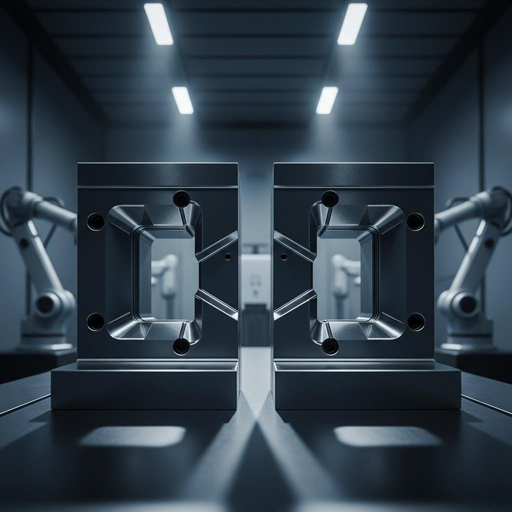
Temelde bir kalıp aracı, her pres darbesi sırasında birlikte çalışan eşleştirilmiş bileşenlerden - genellikle bir punch (çıkartma) ve bir kalıp bloğu - oluşur. Punch, gerdirme, bükme veya delme işlemlerini gerçekleştirirken, kalıp bloğu iş parçasını güvenli bir şekilde sıkıştırır ve tamamlayıcı şekillendirme hareketi sağlar. Bileşenler arasındaki bu iş birliği, sac metal şekillendirmeyi o kadar dikkatli ve tekrarlanabilir kılar.
Kalıplar sadece aletler değildir – üretim kalitesinin DNA'sıdır. Tek bir hassas kalıp, mikronlar içinde orijinal tasarım özelliklerine uyan milyonlarca özdeş parça üretebilir.
Metal şekillendirme işlemleri, basit bükme ve kesme işlemlerinden karmaşık derin çekme ve damgalama işlemlerine kadar geniş bir teknik yelpazesi kapsar. Her işlem, malzeme akışı, boşluklar ve iş parçasının mekanik özellikleri dikkatle göz önünde bulundurularak özel olarak tasarlanmış kalıplar gerektirir.
Modern İmalatta Neden Kalıplar Önemlidir
Kaliteli kalıplara yapılan yatırımın değeri, başlangıçta yapılan kalıp maliyetlerini çok aşar. Doğru şekilde tasarlanmış ve bakımı uygun şekilde yapılmış kalıplar, parça kalitesi, üretim sürekliliği ve genel üretim verimliliği üzerinde doğrudan etki yaratır. Bu aletlerin nasıl çalıştığını anladığınızda, tedarikçileri değerlendirmenize, bakım ihtiyaçlarını öngörmenize ve üretim sonuçlarını optimize etmenize yardımcı olan bir karar verme çerçevesi kazanırsınız.
Bu makale boyunca, temel kavramlardan başlayarak malzeme seçimi, tasarım ilkeleri ve yaşam döngüsü yönetimi konularına kadar bir yolculuğa çıkacaksınız. Otomotiv gövde panelleri, elektronik konektör muhafazaları ya da hassas bağlantı parçaları için kalıp belirtiminde bulunuyorsanız, ileride yer alacak bilgiler, temel girişler ile teknik ürün katalogları arasındaki boşluğu doldurur ve gerçek dünya üretim kararlarınız için pratik içgörüler sunar.
Şekillendirme Kalıplarının Türleri ve Uygulamaları
Metal şekillendirme kalıplarının ne olduğunu ve neden önemli olduklarını artık bildiğinize göre, mevcut farklı kalıp türlerini inceleyelim. Doğru kalıp türünü seçmek, verimli bir üretim süreci ile maliyetli verimsizlikler arasında fark yaratabilir. Her kategori, basit kesme işlemlerinden karmaşık damgalama-bükme dizilerine kadar belirli şekillendirme operasyonlarında üstün performans gösterir; bu farklılıkları anlayarak, tam olarak üretim gereksinimlerinize uygun kalıpları seçebilirsiniz.
Yüksek Hacimli Üretim İçin İlerlemeli Kalıplar
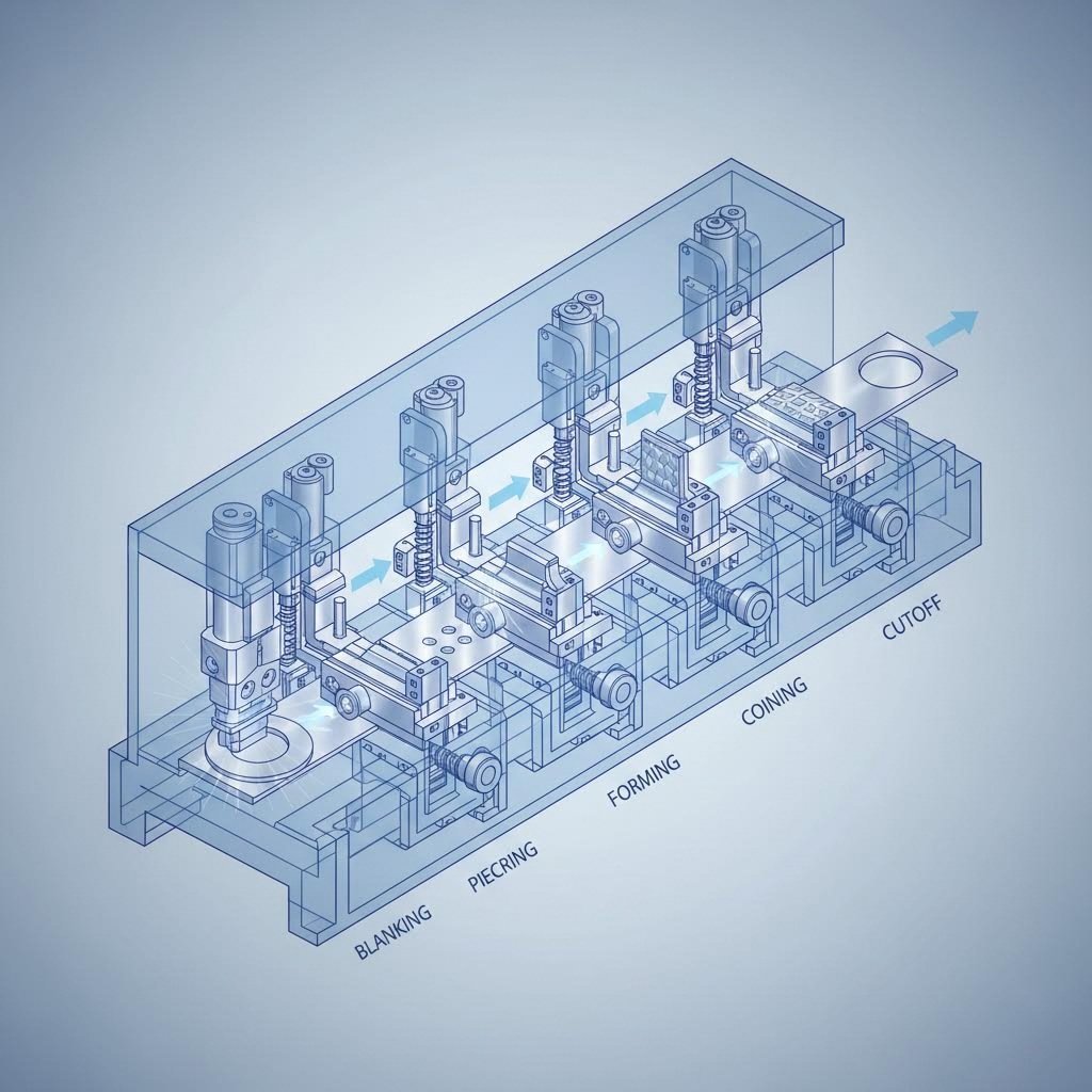
Bir sac levha şeridinin, sonunda tamamlanmış bir parça düşürülünceye kadar sırayla farklı işlemler yapan istasyonlar dizisi boyunca ilerlediğini hayal edin. İşte progresif kalıpların güzelliği budur. Bu gelişmiş araçlar, metalin her pres darbesinde bir sonraki aşamaya ilerlediği şekilde birden fazla istasyonu sıralı olarak düzenler.
Progresif kalıplar, farklı türde şekillendirme işlemlerini aynı anda gerçekleştirir: bir istasyonda kesme, bir sonraki istasyonda delme, daha ilerideki bir istasyonda bükme ve son istasyonda nihai kenar temizleme. Bu kalıp süreci, işlemler arasında elle müdahaleyi ortadan kaldırarak üretim hızını büyük ölçüde artırırken, üstün tutarlılığı korur.
Otomotiv üreticileri neden progresif kalıpları sever? Çünkü ayaklıklar gibi bileşenleri üretir , klipsler ve dakikada 1.000’den fazla parça hızında elektrik bağlantı elemanları. Elektronik şirketleri, çok sayıda hassas özelliğe sahip karmaşık bağlantı elemanı muhafazaları üretmek için bunlardan yararlanır. Üretim hacminiz başlangıç yatırımını haklı çıkarıyorsa, ilerleyici kalıplar eşsiz verimlilik ve tekrarlanabilirlik sağlar.
Transfer ve Bileşik Kalıp Uygulamaları
Parçalarınız ilerleyici kalıplar için çok büyük veya karmaşık olduğunda ne olur? Bu zorluğu çözmek üzere transfer kalıpları devreye girer. İlerleyici kalıpların aksine, burada parçalar şeride bağlı kalmaz; iş parçası erken aşamada ayrılarak mekanik olarak istasyonlar arasında taşınır. Bu yaklaşım, başka herhangi bir yöntemle üretmenin pratik olmadığı daha büyük bileşenleri ve daha karmaşık montajları işleyebilir.
Transfer kalıpları, havacılık ve ağır makine uygulamalarında öne çıkar. Yakıt tankı kabukları, yapısal paneller veya derin çekme işlemiyle üretilen muhafazalar gibi örnekler düşünülebilir. Kontrollü transfer süreci, büyük boyutlu bileşenlerde bile sıkı toleransları korur; bu nedenle bu kalıplar, zorlu şekillendirme operasyonu gereksinimleri için vazgeçilmezdir.
Bileşik kalıplar ise farklı bir yaklaşım benimser — tek bir strokta birden fazla işlem gerçekleştirir. Bir şeklin kesilmesini aynı anda delik açma işlemiyle birlikte yapmanız mı gerekiyor? Bileşik kalıp her iki işlemi de anında gerçekleştirir. Bu verimlilik, özellikle tıbbi cihaz ve tüketici ürünleri üretiminde orta hacimli, orta karmaşıklıkta parçaların üretiminde onları ideal hale getirir.
Daha basit gereksinimler için tek istasyonlu kalıplar (basit kalıplar olarak da bilinir) her strokta yalnızca bir işlem yapar. Maliyet açısından avantajlıdır, bakımı kolaydır ve düşük ila orta üretim hacimleri veya temel kesme ya da bükme gibi basit görevler için mükemmeldir.
Metal Şekillendirme ve Kopyalama İşlemlerini Anlamak
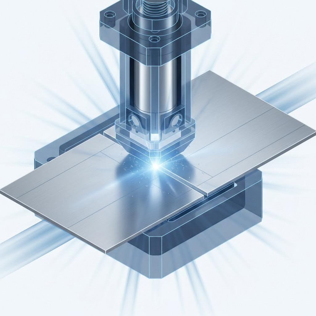
Her kalıp türü, belirli şekillendirme işlemlerinde üstün performans gösterir. Kesme kalıpları, levha malzemeden düz şekilleri keser. Delme kalıpları, hassas delikler açar. Şekillendirme kalıpları, metalin bükülmesi, kıvrılması veya gerilmesi yoluyla yeniden şekillendirilmesini sağlar. Çekme kalıpları, bardak veya derin muhafazalar gibi içi boş şekiller elde etmek için levha metalini boşluklara çeker.
Bunun yanı sıra, yüksek hassasiyetli özel bir işlem olan metal şekillendirme damgalama işlemi de vardır. Damgalama kalıpları, mükemmel yüzey kalitesine sahip ayrıntılı özellikleri oluşturmak için aşırı basınç uygular. Takı bileşenleri, tıbbi cihazlar ve dekoratif elemanlar genellikle bu düzeyde hassasiyet gerektirir. Bu süreç, diğer yöntemlerin başaramadığı keskin kenarlar, ince detaylar ve boyutsal olarak çok doğru özellikler üretir.
| Die türü | En Uygun Kullanım Alanı | Üretim hacmi | Karmaşıklık Seviyesi | Tipik Sektörler |
|---|---|---|---|---|
| Ilerici kalıplar | Sürekli şeritten üretilen çok aşamalı parçalar | Yüksek (100.000+ parça) | Yüksek | Otomotiv, Elektronik, Ev Aletleri |
| Taşıma matları | Büyük veya derin çekmeli bileşenler | Yüksek | Çok yüksek | Havacılık, Ağır Makineler, Otomotiv |
| Bileşik kalıplar | Birden fazla eşzamanlı işlem | Orta seviye yüksek | Orta | Tıbbi Cihazlar, Tüketici Ürünleri |
| Basit kalıplar | Tek işlem (kesme, bükme, delme) | Düşük ile Orta | Bu | Genel İmalat, Prototipleme |
| Damgalama Kalıpları | Yüksek hassasiyetli ayrıntılı özellikler | Değişir | Yüksek | Takı, Tıbbi, Dekoratif Parçalar |
Kalıp Türlerini Gereksinimlerinize Uyarlama
Peki nasıl seçim yaparsınız? Üç temel faktörü değerlendirmekle başlayın: parça karmaşıklığı, üretim hacmi ve malzeme türü. Çoklu özelliklere sahip karmaşık bileşenler genellikle ilerleyici veya taşıma kalıplarını işaret eder. Daha basit geometriler ise sadece bileşik veya tek istasyonlu çözümlere ihtiyaç duyabilir.
Üretim hacmi, maliyetleri büyük ölçüde etkiler. İlerleyici kalıplar önemli bir başlangıç yatırımı gerektirir ancak yüksek hacimlerde parça başına en düşük maliyeti sağlar. Prototip üretimi veya düşük hacimli özel parçalar için daha basit şekillendirme kalıpları, birim maliyetlerin yüksek olmasına rağmen finansal olarak daha mantıklıdır.
Malzeme dikkate alınması gereken bir diğer faktördür. Farklı metaller stres altında farklı davranışlar sergiler. Alüminyum kolay akar ancak daha fazla geri yaylanma gösterir. Yüksek dayanımlı çelikler, sağlam kalıp ekipmanları ve hassas açıklıklar gerektirir. Tutkal seçiminiz, tutarlı sonuçlar elde edebilmek için bu malzemeye özel davranışları dikkate almalıdır.
Bu kalıp türleri temeli oluşturulduktan sonra bir sonraki kritik karar, kalıpların kendileri için uygun malzemeler ve kaplamaların seçilmesini içerir; bu faktörler, zorlu üretim koşulları altında takım ömrünü ve performansını doğrudan belirler.
Uzun Ömürlü Takımlar İçin Kalıp Malzemeleri ve Kaplamalar
Doğru kalıp türünü seçmek yalnızca yarısıdır. Takım kalıplarınız için seçtiğiniz malzemeler ve yüzey işlemlerinin, bu kalıpların ne kadar süre performans göstereceğini ve kaliteli parçaları ne kadar tutarlı şekilde üreteceğini doğrudan belirler. Bunu şöyle düşünün: En akıllıca tasarlanmış kalıp bile, yetersiz malzemelerden yapılmışsa veya yüksek hacimli metal işleme koşullarının sert gerçekliklerine karşı korunmamışsa erken başarısızlık gösterecektir.
Kalıp çeliği seçimi, mevcut en sert malzemenin seçilmesiyle sınırlı değildir. Bu, birbirleriyle çatışan özellikler arasında dikkatli bir denge kurmayı gerektirir: sertlik ile tokluk, aşınmaya dayanıklılık ile işlenebilirlik. Bu ödünleşimleri anlama, belirli metal şekillendirme uygulamalarınız için optimum performans sağlayan kalıp ekipmanlarını belirtmenize yardımcı olur.
Talepkar Uygulamalar İçin Kalıp Çelikleri
Üç kalıp çelik sınıfı, her biri farklı çalışma koşulları için tasarlanmış olarak kalıp imalatı alanında öncülük eder. Seçiminiz, muhtemelen karşılaşacağınız arızalara bağlıdır: aşındırıcı aşınma mı, darbe çatlaması mı yoksa termal yorulma mı.
D2 Kesici Çelik d2, soğuk işlem uygulamalarının işgücüdür. Bu yüksek karbonlu, yüksek kromlu çelik, bol miktardaki krom karbürleri sayesinde olağanüstü aşınmaya dayanıklılık sağlar. Tipik çalışma sertliği 58–62 HRC olan D2, aşındırıcı aşınmanın baskın olduğu kesme, delme ve şekillendirme işlemlerinde üstün performans gösterir. Kaynakça göre İmalatçı d2, genellikle 409 ve 439 gibi paslanmaz çelik kalitelerinin üretimi için tercih edilir; ancak yüksek krom içeriği yapıştırıcı bağlanma sorunlarına neden olabilir ve bu da ek kaplamalar gerektirebilir.
A2 Takım Çeliği aşınmaya dayanıklılık ile tokluk arasında dengeli bir çözüm sunar. Hava sertleşebilen özelliği, ısı işlemi sırasında boyutsal kararlılığı sağlar ve karmaşık kalıp bileşenlerinde deformasyonu azaltır. A2 genellikle 57–62 HRC sertlik değerine ulaşır ve hassas kesme kalıpları, şekillendirme kalıpları ve sertleştirme sonrası dar toleranslar gerektiren uygulamalar için oldukça uygundur.
S7 takım çeliği tokluğu her şeyin üzerinde önceliklendirir. Kalıp bileşenleriniz ani yükleme koşullarına maruz kalıyorsa — örneğin ağır işlevli presleme işlemleri ya da önemli darbe kuvvetleriyle çalışan işlemler — S7, çatlama veya kırılma olmadan enerjiyi emer. Çalışma sertliği aralığı 54–58 HRC’dir; D2’ye kıyasla biraz daha düşüktür ancak bu değiş-tokuş, felaket niteliğindeki arızalara karşı önemli ölçüde artırılmış direnç sağlar.
- Sertlik Değerleri: D2: 58–62 HRC; A2: 57–62 HRC; S7: 54–58 HRC
- Aşınma Direnci: D2, aşındırıcı aşınmaya karşı üstün direnç sunar; A2, genel olarak iyi aşınma özelliklerine sahiptir; S7, darbe dayanımını artırmak için bir miktar aşınma direncinden vazgeçer
- Sertlik: S7, belirgin şekilde öndedir; A2, orta düzey tokluk sağlar; D2, karbür içeriği nedeniyle ani yükleme altında daha kırılgandır
- Makinalandırma: A2, normalleştirilmiş (tavlı) durumda en kolay işlenebilen malzemedir; S7 hemen arkasından gelir; D2 ise karbür içeriği nedeniyle en zor işlenebilen malzemedir
Karbür Bileşenlerinin Kullanılmasının Anlamlı Olduğu Durumlar
Bazen hatta yüksek kaliteli çelik kalıplar bile bu zorlu koşullara dayanamaz. Üretim hacmi milyonlara ulaştığında ya da yüksek mukavemetli çelik gibi aşındırıcı malzemeler şekillendirildiğinde tungsten karbür bileşenler devreye girer. Karbür takımlar genellikle 85–92 HRA sertlik değerlerine ulaşır — bu değer, herhangi bir takım çeliğinden çok daha yüksektir.
Pazarlık unsuru nedir? Karbür kırılgan ve pahalıdır. Aşındırıcı aşınmaya karşı direnci son derece yüksektir ancak darbe yüklemesi altında çatlayabilir. Akıllı kalıp tasarımı, karbürü stratejik olarak kullanır — yüksek aşınma gösterebilecek noktalara, örneğin punch uçlarına ve kesme kenarlarına karbür takımları yerleştirilirken, daha tok malzemeler diğer bölgelerde tercih edilir yapısal bileşenler için çelik kalıp plakaları bu hibrit yaklaşım, tam karbür yapı maliyetini ödemeden kalıbın ömrünü maksimize eder.
Yüksek hacimli otomotiv presleme uygulamalarında, kalıplar bakım gerektirmeden 500.000+ parça üretebilir; bu durumda karbür uçlu punch’lar, katı çelik alternatiflere kıyasla iki kat veya daha fazla performans artışı sağlayabilir.
İş parçası özelliklerine göre malzeme seçimi
Ne ürettiğiniz, ne kadar parça ihtiyacınız olduğu kadar önemlidir. Farklı iş parçası malzemeleri, kalıbınızın bileşenleri için farklı zorluklar yaratır.
Çelik Şekillendirme: Karbon çelikleri ve yumuşak çelikler, D2 veya A2 kalıp bileşenlerine iyi tepki verir. Daha yüksek mukavemetli çelikler ise daha sert kalıp yüzeyleri gerektirir; hızlandırılmış aşınmaya karşı karbür gömülü parçalar veya gelişmiş kaplamalar düşünülmelidir.
Alüminyum Şekillendirme: Alüminyumun yumuşaklığı, kalıplara zarar vermeden şekillendirilebileceğini düşündürebilir; ancak yapışma aşınması gerçek tehdit kaynağıdır. Alüminyum, kalıp yüzeylerine yapışma ve kazınma eğilimindedir; bu nedenle malzeme geçişini önlemek amacıyla cilalı kalıplar ve özel kaplamalar gereklidir.
Bakır Alaşımları Şekillendirme: Pirinç ve bronz alaşımları, alüminyuma benzer yapışkan aşınmaya neden olabilir. Yüksek parlaklıkta kalıp yüzeyleri ve uygun kaplamalar, parçanın kalitesini korurken yapışmayı en aza indirir.
Kalıp Ömrünü Uzatan Yüzey İşlemleri
Ham kalıp çeliği nadiren doğrudan üretimde kullanılır. Yüzey işlemleri, aşınmaya dayanıklı ve sürtünmeyi azaltan koruyucu katmanlar ekleyerek kalıp ömrünü önemli ölçüde uzatır.
Nitrürleme çelik yüzeyine nüfuz eden sert bir demir-nitür tabakası oluşturur. Oto/Çelik Ortaklığı araştırması, krom kaplamaya kıyasla nitürlemenin yüksek yük altında aşınmaya karşı daha iyi performans gösterdiğini doğrulamaktadır; çünkü daha kalın nitür tabakası hem dikey hem de teğetsel kayma yüklerini daha iyi emer. Bu işlem, yoğun presleme kuvvetlerine maruz kalan kalıp bileşenleri üzerinde özellikle etkilidir.
Kromozlama sürtünmeyi azaltan ve düşük yükte aşınmaya dayanıklılığı artıran ince, sert bir yüzey kaplaması oluşturur. Ancak krom yalnız başına yüksek yükler altında çatlayabilir, dökülebilir veya deform olabilir. Aynı araştırma, nitrürleme ile krom kaplamayı birlikte uygulamanın — bu yönteme çift katmanlı kromlama (duplex chroming) denir — her iki işlemi ayrı ayrı uygulamaktan önemli ölçüde daha üstün sonuçlar verdiğini ortaya koymuştur. Özellikle beyaz tabaka içermeyen nitrürlenmiş bir alt tabakaya uygulanan ince krom kaplama, uzun süreli test çevrimleri boyunca en iyi aşınma direncini sağlamıştır.
PVD Kaplamalar (Fiziksel Buhar Biriktirme) yöntemiyle titanyum nitrür veya krom nitrür gibi ultra-sert malzemeler kalıp yüzeylerine biriktirilir. Bu kaplamalar, yapışkan aşınmayı ve malzeme tutulmasını (material pickup) önlemekte oldukça etkilidir; bu nedenle alüminyum veya paslanmaz çelik şekillendirme işlemlerinde idealdir. Dikkat edilmesi gereken bir nokta: Bazı PVD süreçleri uygulama sırasında yüksek sıcaklıklar gerektirir; düşük temperleme sıcaklığına sahip takım çelikleri bu süreçte yumuşayabilir ve bu durumda yeniden sertleştirme işlemi gerekebilir.
Üretim Hacmine Göre Sertlik Gereksinimleri
Üretim beklentileriniz sertlik spesifikasyonlarını belirlemelidir. Düşük hacimli üretimler, değiştirilmesi veya tamiri daha kolay olan, daha yumuşak ancak tok kalıp malzemelerine tahammül edebilir. Yüksek hacimli üretim ise bakım kesintilerini en aza indirmek için maksimum sertlik ve aşınmaya dayanıklılık gerektirir.
10.000 parçadan az olan prototip ve kısa seri üretimler için genellikle daha düşük maliyetli alevle sertleştirilmiş 4140 çeliği yeterlidir. 10.000-100.000 parça aralığındaki orta hacimli üretimler için genellikle uygun ısıl işlem uygulanmış D2 veya A2 çelikleri tercih edilir. 100.000 parçadan fazla olan yüksek hacimli üretimlerde kritik aşınma noktalarında ileri teknoloji kaplamalı premium çelikler veya karbür takımlar gerekebilir.
Maliyet değerlendirmeleri başlangıçtaki malzeme fiyatlarını aşar. Sektörün uzmanlarının da belirttiği gibi, daha düşük kaliteli kalıp çelikleriyle oluşan duruş süresinin maliyeti, daha yüksek kaliteli malzemeler için ödenen ek ücreti genellikle aşar. Bazı kalıp çelikleri geleneksel çeliklere kıyasla iki kat daha üstün performans gösterir; bu nedenle zorlu uygulamalar için bu yatırım oldukça değerlidir.
Kalıp bileşenleriniz için doğru malzemeler ve kaplamalar seçildikten sonra bir sonraki adım, üretim kusurlarını önceden önlemeye yönelik sağlam tasarım ilkelerini uygulamaktır; bu ilkeler, delici açıklıklarından geri yayılma telafisine kadar her şeyi yönetir.
Üretim Kusurlarını Önleyen Kalıp Tasarım İlkeleri
Kalıplarınız için yüksek kaliteli malzemeler ve kaplamalar seçtiniz. Şimdi gerçek meydan okuma başlıyor: kusursuz parçaları tutarlı şekilde üreten kalıplar tasarlamak. Bu aşamada yapılan kötü tasarım kararları, en iyi malzemeleri bile etkisiz hâle getirebilir ve çatlaklara, buruşmalara, boyutsal hatalara ve maliyetli üretim gecikmelerine yol açabilir. İyi haber şu ki: bu sorunları başlangıçta önleyen kanıtlanmış tasarım ilkeleri mevcuttur.
Kalıp yapımı, mühendislik bilimini pratik deneyimle birleştirir. Peki kalıp yapımı temelde nedir? Parça gereksinimlerini, malzeme akışını kontrol eden, geri yayılmayı telafi eden ve binlerce veya milyonlarca üretim döngüsü boyunca sıkı toleransları koruyan kalıp geometrisine dönüştürme sanatıdır. Başarılı kalıpları sorunlu olanlardan ayıran ilkeleri inceleyelim.
Kritik Boşluklar ve Toleranslar
Punch-to-die (çıkartıcı-kalıp) boşluğu, küçük bir ayrıntı gibi görünebilir; ancak aslında tüm metal şekillendirme sürecinde en önemli kararlardan biridir. Çok az boşluk aşırı aşınmaya, yapışmaya (galling) ve erken kalıp arızasına neden olur. Çok fazla boşluk ise kenar kesintileri (burrs), pürüzlü kenarlar ve boyutsal değişkenliğe yol açar.
Kapama ve delme işlemlerinde optimal boşluk genellikle malzeme kalınlığının her bir yanında %5 ila %10 arasındadır; ancak bu değer, malzeme türüne bağlı olarak önemli ölçüde değişebilir. Yumuşak alüminyum için %3–%5 civarında boşluklar gerekebilirken, yüksek mukavemetli çelikler genellikle %8–%12 aralığında boşluk gerektirir. Bu parametreyi doğru belirlemek, yalnızca genel kuralları uygulamakla kalmaz, aynı zamanda iş parçanızın özel özelliklerini anlamayı da gerektirir.
Malzeme akışı dikkatleri, basit boşlukların ötesine geçer. Metal bir şekillendirme sürecinden geçerken, en az direnç yoluyla hareket eder. Keskin köşeler gerilme yoğunluklarına neden olur ve çatlaklara yol açar. Yetersiz köşe yarıçapları (radius) akışı kısıtlar ve malzemeyi aşırı inceltir. Tecrübeli kalıp tasarımcıları bu akış desenlerini önceden tahmin eder ve malzeme hareketini kontrol etmek amacıyla geniş köşe yarıçapları, pürüzsüz geçişler ile stratejik olarak yerleştirilmiş çekme çıkıntıları (draw beads) kullanır.
Gerilim geri dönüşü (springback) telafisi ise başka bir kritik zorluk sunar. Şekil verme işleminden sonra endüstri araştırmalarının doğruladığı gibi yaylanma, bükme kuvveti kaldırıldıktan sonra malzemenin elastik geri dönüşü nedeniyle meydana gelir. Yüksek mukavemetli çelikler ve alüminyum alaşımları özellikle belirgin yaylanma gösterir; bu durum bazen istenen açıdan 5° veya daha fazla geri sıçramaya neden olabilir. Başarılı şekillendirme süreçleri, bu elastik geri dönüşü aşırı bükme, optimize edilmiş kalıp geometrisi veya çok aşamalı şekillendirme dizileri ile dikkate almalıdır.
Üretilebilirlik ve Dayanıklılık İçin Tasarım
Etkili kalıp tasarımı, anlayışı sistematik olarak geliştiren mantıksal bir sırayı takip eder. Adımların atlanması, ileride maliyetli düzeltmelerle sonuçlanır. İşte kanıtlanmış yaklaşım:
- Parça Analizi: Nihai bileşeni dikkatlice inceleyin. Kritik boyutları, yüzey kalitesi gereksinimlerini ve malzeme özelliklerini belirleyin. Parçanın nihai montajında nasıl işlev gördüğünü ve hangi özelliklerin en çok önem taşıdığını anlayın.
- Proses planlaması: Gerekli geometriyi en iyi şekilde elde etmek için hangi şekillendirme süreçlerinin kullanılacağı belirlenir. Parça, çekme, bükme, kesme, delme veya bunların kombinasyonlarını mı gerektirir? İşlem sırası belirlenir ve olası sorun alanları tespit edilir.
- Şerit düzeni: İlerlemeli kalıplar için parçaların şerit içinde nasıl yerleşeceği optimize edilir. Taşıyıcı şeritlerin ve yönlendirici deliklerin (pilot) yeterli olması sağlanırken malzeme kullanım oranı maksimize edilir. Buna göre Keysight'ın şekillendirme simülasyonu araştırmasına göre, simülasyon yazılımı, malzeme kullanım oranını maksimize etmek amacıyla başlangıçtaki düz sac konturunun optimizasyonunu sağlar.
- Kalıp İnşa Tasarımı: Genel kalıp mimarisi – kalıp tabanları, kılavuz sistemleri, sökücü mekanizmaları ve istasyon düzenlemeleri – belirtilir. Üretim kuvvetlerine karşı eğilmeyecek kadar yeterli dayanım ve rijidite sağlanır.
- Bileşen Spesifikasyonu: Punşlar, kalıp iç parçaları, yönlendirici delikler (pilotlar) ve yaylar gibi bireysel bileşenler ayrıntılı olarak tanımlanır. Her bir bileşen için maruz kalacak yükler ve aşınma koşullarına göre uygun malzemeler ve kaplamalar seçilir.
Karmaşık Parçalar İçin İleri Düzey Dikkat Edilmesi Gerekenler
Yüksek mukavemetli malzemelerin şekillendirilmesinde tane yönü etkileri önemli hâle gelir. Sac metal, haddeleme yönüne paralel ve dik olmak üzere farklı mekanik özellikler gösterir. Tane yönüne dik olarak bükme işlemi genellikle daha az geri yaylanma ile daha iyi sonuçlar verirken, tane yönüne paralel olarak bükme kenar çatlaklarına neden olabilir. Sac metal şekillendirme sürecinizi, sac kesimi düzenlemesi ve süreç planlaması aşamalarında bu yönsel özellikleri dikkate almalıdır.
Derin çekme oranları, derin çekmeli parçaların üretim sırasında başarıyla şekillenip şekillenmeyeceğini veya çatlayacağını belirler. Bu oran, sac kesimi çapının punch çapına oranını ifade eder; malzemeye özgü sınır değerlerin aşılması başarısızlığa yol açar. Yumuşak çelik için ilk çekme işleminde maksimum çekme oranları genellikle 1,8 ila 2,0 arasında değişir ve ardışık yeniden çekme işlemlerinde bu değerler azalır. Alüminyum ve paslanmaz çelik için ise bu sınırlar daha kısıtlayıcıdır.
Boşta tutucu basıncı, çekme işlemlerinde malzeme akışını kontrol eder. Çok az basınç, fazla malzemenin buruşmasına neden olarak buruşların oluşmasına izin verir. Çok fazla basınç ise akışı kısıtlayarak çatlaklara ve aşırı incelmeye neden olur. Optimal basınç aralığını bulmak, belirli malzemenizin davranışını anlama gerektirir; bu da simülasyonun değerini kanıtlayan bir başka alandır.
CAE Simülasyonu: Fiziksel kalıp imalatından önce kusurların önlenmesi
Modern şekillendirme süreçleri, çelik kesmeden önce sorunları öngörmek amacıyla Bilgisayar Destekli Mühendislik (CAE) simülasyonuna büyük ölçüde dayanır. Keysight’ın araştırmasında açıklandığı gibi, sac metal şekillendirme simülasyonu, şekillendirme sırasında metal davranışını öngörmek ve analiz etmek için son derece gelişmiş hesaplamalı tekniklerden yararlanır; bunlara sonlu eleman analizi de dahildir.
Simülasyon ne gösterebilir?
- Çatlaklar, buruşmalar ve aşırı incelme gibi şekillendirilebilirlik sorunları
- Gerilim geri dönüşü (springback) büyüklüğü ve yönü; bu, yarı otomatik kalıp telafisi yapılmasını sağlar
- Dijital taşlama veya sanal ışık odası analiziyle görülebilen kozmetik kusurlar
- Tam şekillendirme için gerekli minimum pres kuvveti
- Kalıp aşınmasını etkileyen temas basınçları ve malzeme akış desenleri
Sanal kalıp denemeleri, geleneksel olarak fiziksel yinelemeler üzerinde harcanan süreyi ve maliyeti azaltır. Üretim başlamadan önce imalat kalıbının davranışını simüle ederek mühendisler, takım geometrisini optimize edebilir, açıklıkları ayarlayabilir ve işlem parametrelerini dijital ortamda iyileştirebilir. Bu proaktif yaklaşım, özellikle deneme-yanılma yöntemi son derece maliyetli olacak zorlu malzemeler veya karmaşık geometrilerle çalışırken özellikle faydalıdır.
Doğru fizik tabanlı simülasyonun entegrasyonu, kontrolü büyük büyüklükteki değişkenlikler nedeniyle zor olan yüksek mukavemetli çeliklerde ve alüminyumda geri yayılmayı (springback) öngörmeye yardımcı olur. Sac metal şekillendirme süreci için bu yetenek, takımlama geliştirme sürecini reaktif sorun çözmeden proaktif optimizasyona dönüştürür.
Ses tasarımı ilkeleri, simülasyon yoluyla kurulmuş ve doğrulanmış durumdadır; bir sonraki kritik adım ise üretim gerçekliğini sağlayan fiziksel kalıp bileşenlerini — tasarım amacını üretim gerçekliğine dönüştüren ayaklar, plakalar, kılavuzlar ve hassas elemanları — anlamaktır.
Temel Kalıp Bileşenleri ve İşlevleri
Tasarım ilkelerini ve simülasyon tekniklerini ustalıkla öğrendiniz. Ancak presinizde duran fiziksel kalıp montajı aslında nelerden oluşur? Bireysel bileşenleri — ve bunların birlikte nasıl çalıştığını — anlamak, reaktif bakım ile proaktif kalıp yönetimi arasındaki farkı oluşturur. Bir kalıp bileşenleri setindeki her eleman belirli bir işlev üstlenir ve tek bir parçadaki zayıflık, tüm üretim süreciniz boyunca kalite sorunlarına yol açabilir.
Kalıp ekipmanını, sonucu belirleyen her parçanın katkı sağladığı bir hassas sistem olarak düşünün. Kalıp tabanı (shoe), temeli oluşturur. Yönlendirme pimleri hizalamayı sağlar. Soğutucular (strippers), parçaları temiz bir şekilde ayırır. Pilotlar, malzemenin tam olarak doğru konumlandırılmasını sağlar. Bu ilişkileri anladığınızda, kalıp bakım önceliklerini belirlemek tahmin etmeye dayalı değil, açık ve net bir süreç haline gelir.
Üst ve Alt Kalıp Tabanı (Shoe) Montajları
Kalıp tabanı (shoe), tüm montajın yapısal temelini oluşturur. Langdi Precision’e göre, kalıp seti (die set), kalıp bloğu ve matrisi (punch) hizalı tutar ve üst (üst taban) ile alt (alt taban) plakalardan oluşur; bu plakalar yönlendirme pimleriyle birbirine bağlanır. Bu ağır çelik plakalar pres üzerine monte edilir: alt taban, presin tabla yüzeyine (bed) veya destek plakasına (bolster) sabitlenirken, üst taban, presin hareketli koluyla (ram) bağlantılıdır.
Bu durum üretiminiz açısından neden önemlidir? Kalıp ayakkabıları, devasa presleme kuvvetleri altında şekil değişimine karşı dirençli olmalıdır. Herhangi bir bükülme veya hareket, parçalarınızda doğrudan boyutsal değişime neden olur. Pres uygulamaları için premium kalıp setleri, milyonlarca çevrim boyunca rijitliği korumak amacıyla hassas taşlanmış yüzeyler ve yeterli kalınlık kullanır.
Kalıp plakası (bazen kalıp bloğu olarak da adlandırılır), alt ayakkabıya monte edilir ve kesme veya şekillendirme boşluklarını içerir. Bu, malzemenin aslında dönüştüğü yerdir — bitmiş parçalarınızın şekli burada başlar. Kalıp plakaları için malzeme seçimi genellikle daha önce tartışılan yönergeleri takip eder: yüksek aşınma uygulamaları için D2 çeliği; son derece yüksek üretim hacimleri için karbür takımlar.
Delme tutucuları, çalışan delme uçlarını üst ayakkabıya sabitler. Bu bileşenler, yüksek darbe kuvvetlerine dayanırken delme uçlarını son derece hassas bir şekilde konumlandırmalıdır. Destek plakaları, delme uçlarının ve kalıp düğmelerinin arkasında yer alır ve daha yumuşak ayakkabı malzemesinin yüksek basınç altında deformasyona uğramasını önler. U-Need'in bileşen kılavuzuna göre, destek plakaları, aksi takdirde kalıp yapısına zarar verebilecek yoğun yükleri karşılamak için sertleştirilmiş plakalardır.
Hassasiyeti Sağlayan Hassas Bileşenler
Kılavuz pimleri ve burçlar basit görünse de, üretimleri .0001" (insan saçı kalınlığının yaklaşık dörtte biri) tolerans içinde gerçekleştirilir. Moeller Precision Tool'a göre, bu bileşenler, üst ve alt kalıp plakalarını olağanüstü bir hassasiyetle hizalamak için birlikte çalışır.
Sektörde iki ana tip hakimdir:
- Sürtünmeli (düz) kılavuz pimleri: Burç iç çapından biraz daha küçüktür; böylece doğru yönlendirme sağlar ancak kalıp yarım parçalarının ayrılmasında daha fazla kuvvet gerektirir.
- Toplu rulmanlı kılavuz pimleri: Alüminyum kafesler içinde dönen bilyalı rulmanlar üzerinde kayarak kalıp ayırma işlemini kolaylaştırır – kullanım kolaylığı nedeniyle artık sektör standardıdır
Soyucu plakalar, kritik bir çift işlev görür. İlk olarak, şekillendirme veya kesme işlemlerinde iş parçasını düz tutarlar. İkinci olarak, çubuk geri çekildiğinde malzemeyi çubuktan soyarlar – bu işlev olmazsa, malzemenin elastikiyeti parçaların çubuklara yapışmasına ve üretimde tıkanıklığa neden olurdu. Kalıp yayları (mekanik spiral veya azot gazı ile çalışan) soyucu hareketini sağlayan kuvveti sağlar.
Pilotlar, ilerlemeli kalıpların doğruluğunda sessiz kahramanlardır. Bu hassas pimler, her istasyonda malzeme şeridini hizalar ve her işlemin tam olarak doğru konumda gerçekleşmesini sağlar. Hatta küçük bir hizalama hatası bile çoklu istasyonlarda birikerek kabul edilebilir toleransları hurda parçalara dönüştürebilir. Dakikada yüzlerce darbeden oluşan yüksek hızlı işlemlerde pilotlar, her çevrimde güvenilir şekilde etkinleşmelidir.
| Bileşen Adı | Ana işlev | Genellikle Kullanılan Malzeme | Bakım Önceliği |
|---|---|---|---|
| Kalıp Tabanı (Üst/Alt) | Yapısal temel; pres üzerine monte edilir | Çelik veya Alüminyum aleys | Düşük – çatlaklar/kullanım izleri için kontrol edin |
| Ölçü plakası | Şekillendirme/kesme boşluklarını içerir | D2, A2 takım çeliği; karbür kesici uçlar | Yüksek – düzenli olarak bilenmeli/kontrol edilmelidir |
| Darbe tutucu | Çekicileri sabitler ve konumlandırır | Sertleştirilmiş takım çeliği | Orta – hizalama kontrol edilmelidir |
| Rehber Pimler ve Burçlar | Üst ve alt kalıp yarısını hizalar | Sertleştirilmiş, hassas taşlanmış çelik | Orta – yağlaması kritiktir |
| Şerit Ayırma Plakası | Malzemeyi tutar; parça kesimini delici ile gerçekleştirir | Takım çeliği, bazen sertleştirilmiştir | Yüksek — aşınma parça kalitesini etkiler |
| Pilotlar | Şerit malzemeyi her istasyonda hizalar | Sertleştirilmiş takım çeliği; karbür uçlar | Yüksek — doğruluk açısından kritiktir |
| Destek Plakaları | Ayakkabının yük altında deformasyona uğramasını önler | Sertleştirilmiş Demir | Düşük — periyodik olarak kontrol edilmelidir |
| Kalıp Yayları | Soyulma/basınç kuvveti sağlar | Krom silikon tel; azot gazı | Orta – zamanında değiştirilmelidir |
Bileşen Kalitesinin Üretim Tutarlılığı Üzerindeki Etkisi
Yüzbinlerce veya milyonlarca parça üreten yüksek hacimli ortamlarda bileşen kalitesi, doğrudan üretim tutarlılığına yansır. Şu durumu göz önünde bulundurun: yalnızca 0,001 inç aşınmış bir yönlendirme pini, her vuruşta üst kalıp montajının tamamının hafifçe kaymasına neden olabilir. Bu kayma başlangıçta tolerans sınırları içinde parçalar üretmenize izin verebilir; ancak bir milyon çevrim boyunca aşınma üssel olarak hızlanır.
Saygın tedarikçilerden temin edilen kalıp takımları, gerekli toleransları sağlamak amacıyla CNC işleme merkezleri, tel eritme ile elektrik deşarj makinesi (EDM) ve hassas taşlama yöntemleriyle üretilir. Sektör kaynaklarının da teyit ettiği üzere bu bileşenlerin üretimi, 3 eksenli ve 5 eksenli CNC frezeleme, yüzey taşlama, profil taşlama ve EDM makineleri gibi özel donanımları gerektirir.
Bileşen kalitesi ile parça tutarlılığı arasındaki ilişki öngörülebilir bir desen izler. Daha dar toleranslara sahip premium bileşenler, doğruluğu daha uzun süre korur ve ayarlar ile tekrar işlenmelerin sıklığını azaltır. Daha düşük kaliteli bileşenler başlangıçta daha ucuz olabilir ancak daha sık değiştirilmeleri gerekir ve üretimde daha fazla kesintiye neden olur.
Bu kalıp aletlerini ve işlevlerini anlamak, sizin için takma pres teknolojisindeki bir sonraki evreye hazırlanmanızı sağlar: CNC işlemenin ve otomasyonun, kalıpların nasıl üretildiğini, nasıl çalıştırıldığını ve gerçek zamanlı olarak nasıl izlendiğini dönüştürdüğü aşama.
Modern CNC ve Otomatik Kalıp Sistemleri
Kalıbınız, tek bir kusurlu parça üretmeden önce başarısız olacağını size söyleyebilirse ne olur? Bu, bilim kurgu değil. Modern şekillendirme imalat süreçleri artık kalıpların nasıl üretildiğini, işletildiğini ve bakımlarının nasıl yapıldığını temelden değiştiren gelişmiş CNC işleyimi, otomasyon ve sensör teknolojilerini entegre etmektedir. Bu ilerlemeler yalnızca kademeli iyileştirmeler değildir; aynı zamanda hassas presleme işlemlerinin ekonomisini yeniden biçimlendirmektedir.
Manuel sistemlerden otomatik sistemlere geçiş, son yirmi yıl içinde şekillendirme imalat sürecinde gerçekleşen en önemli dönüşümlerden biridir. Bu teknolojileri anlamak, tedarikçilerinizi değerlendirmenize, ekipmanları belirtmenize ve üretim stratejinizi optimize etmenize yardımcı olur.
Kalıp Üretiminde CNC İşleme
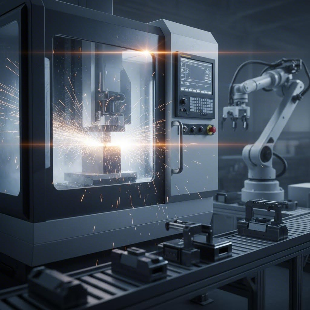
Modern kalıp atölyeleri, karmaşık geometriler boyunca mikron düzeyinde hassasiyeti nasıl elde eder? Cevap, tel eritme ile elektrik deşarjı (wire EDM) ve hassas taşlama gibi özel işlemlerle uyumlu çalışan gelişmiş CNC işleme merkezlerinde yatmaktadır.
Çok eksenli CNC frezeleme makineleri — genellikle 3 eksenli veya 5 eksenli yapılandırmalar — kalıp bileşenlerini takım çeliği ham parçalardan kaba ve ince işleme tabi tutar. Beş eksenli makineler, karmaşık yüzeylere neredeyse her açıdan yaklaşabildikleri için kalıp işlemenin özellikle değerli bir çözümüdür; bu da çoklu tezgâh ayarlarını ve iş parçalarının yeniden konumlandırılmasıyla ortaya çıkan biriken hataları ortadan kaldırır.
Tel Elektrik Deşarjla İşleme (tel EDM), geleneksel işlemenin yapamadığı işlemlerle başa çıkar. Sertleştirilmiş D2 takım çeliğini karmaşık punch profillerine kesmeniz veya keskin iç köşeler oluşturmanız gerektiğinde tel EDM tam da bu ihtiyaca cevap verir. Bu süreç, malzemenin sertliğinden bağımsız olarak elektrik deşarjları kullanarak malzemeyi aşındırır ve geleneksel kesme takımlarını yok edecek özelliklerde bile ±0,0001" (inch) toleranslar elde edilmesini sağlar.
Kesinlikli taşlama, kritik makine kalıp bileşenlerinde nihai yüzey işleyişini sağlar. Yüzey taşlama makineleri, kalıp plakalarını ve destek plakalarını kesin spesifikasyonlara göre düzleştirir. Profil taşlama makineleri, punch kontürlerini ve kalıp açıklıklarını şekillendirir. Silindirik taşlama makineleri ise, kalıbın sorunsuz ve doğru çalışmasını sağlayan toleranslarda yön verici pimleri ve burçları işler.
Bu teknolojilerin entegrasyonu, modern kalıp atölyelerinin daha hızlı ve daha doğru araç takımı üretmesini sağlar. CAD/CAM yazılımı, tasarım amacını doğrudan makine talimatlarına dönüştürerek yorum hatalarını azaltır ve tasarım değişiklikleri olduğunda hızlı yinelemelere olanak tanır.
Tutarlı Sonuçlar İçin Otomasyon Entegrasyonu
Otomasyon, kalıp bileşenlerinin işlenmesini aşarak pres operasyonlarının kendisini dönüştürmektedir. Otomatik kalıp değiştirme sistemleri, üretim hücrelerinin farklı kalıplar arasında saatler yerine dakikalar içinde geçiş yapmasını sağlayan önemli bir ilerlemedir.
Hızlı kalıp değişimi (QDC) sistemleri, standartlaştırılmış kalıp montaj arayüzlerini, hidrolik sıkma mekanizmalarını ve otomatik taşıma arabalarını kullanarak değişim süresini en aza indirir. Bir zamanlar iki ya da üç saat süren ve uzman teknisyenlerin müdahalesini gerektiren bu işlem, artık on dakikadan daha kısa sürede tamamlanabilmektedir. Aynı pres hattında birden fazla parça numarası üreten üreticiler için bu esneklik, doğrudan artan kapasite ve tepki verme hızı anlamına gelmektedir.
Robotik parça işleme, otomasyon avantajlarını daha da artırır. Eklemlendirilmiş robotlar, ham malzemeleri yükler, parçaları istasyonlar arasında taşır ve bitmiş bileşenleri insan müdahalesi olmadan boşaltır. Bu durum, nöbetler boyunca kalite varyasyonlarına neden olan operatör yorgunluğunu ortadan kaldırırken sürekli üretim yapılmasını sağlar.
Ancak gerçek oyun değiştirici, gerçek zamanlı kalıp izleme amacıyla sensör entegrasyonudur. Modern şekillendirme sistemleri, kuvvet, konum, sıcaklık ve titreşimi sürekli olarak ölçen sensörleri doğrudan kalıp gruplarının içine yerleştirir. Buna göre applied Sciences dergisinde yayımlanan araştırmaya göre , kuvvet veri analizi, kalite bozulmasının, kalıp hasarının ve kalıp dışı bileşen hasarının temsilci arızasını gösteren göstergeleri tespit edebilir — bu genellikle gerçek arıza meydana gelmeden saatler öncesidir.
Sensör Teknolojisi Aracılığıyla Tahminî Bakım
Dördüncü istasyondaki delme ucunuzun yaklaşık sekiz saat içinde çatlayacağını bildiren bir uyarı almanızı hayal edin — böylece plansız bir duruş yaşamak yerine, bakımınızı planlı bir molada gerçekleştirmeniz için zaman kazanırsınız. Bu yetenek günümüzde zaten mevcuttur.
Tayvan’da yapılan altı-kalıplı somun üretimi üzerine yapılan araştırma, kuvvet sensörü korelasyon analizinin, arıza şiddetine bağlı olarak kalıp arızalarından 2-8 saat önce uyarı süreleri sağladığını göstermiştir. Çalışma, sapmaların arızalı performansı gösterdiği sağlık eşiği değerlerini belirlemiş; bu da reaktif onarımdan veya aşırı korumacı planlı değiştirme yaklaşımından ziyade koşula dayalı bakım uygulamasına olanak tanımıştır.
Kuvvet Şok Yanıt Spektrumu (SRS) analizi, doğal frekansa karşı anlık darbeyi ölçmesi nedeniyle basit kuvvet profili izlemesinden daha erken arızaları tespit edebildiği için özellikle etkili oldu. Bu duyarlılık, parça kusurları veya felaket niteliğinde kalıp arızaları olarak kendini göstermeden çok önce iç kalıp yapılarında gelişmekte olan çatlaklar gibi ince değişimleri yakalar.
- Azaltılmış Kurulum Zamanı: Otomatik kalıp değiştirme sistemleri, değişim süresini saatlerden dakikalara indirerek üretimde kullanılabilir süreyi artırır ve ekonomik kısa üretim serilerini mümkün kılar.
- Sabit Kalite: Robotik işleme, operatör kaynaklı değişkenliği ortadan kaldırırken otomatik süreç kontrolü, her vuruşta optimal parametreleri korur.
- Gerçek zamanlı izleme: Gömülü sensörler, kuvveti, konumu ve titreşimi sürekli izleyerek parça kalitesini etkilemeden önce sapmaları tespit eder.
- Tahmine Dayalı Bakım Özellikleri: Gelişmiş analitik yöntemler, arızadan saatler önce gelişmekte olan sorunları belirleyerek acil onarım yerine planlı müdahale imkânı sunar.
Modern Otomasyonun ROI Etkisi
Bu teknolojiler kar marjınızı nasıl etkiliyor? Ekonomik gerekçe, bir arada çalışan çok sayıda faktöre dayanmaktadır.
American Micro Industries'in belirttiği gibi, otomasyon hataları azaltır, manuel müdahaleyi en aza indirir ve tutarlılığı sağlar. Bu operasyonel iyileştirmeler doğrudan maliyet tasarrufuna ve kar marjlarının genişlemesine dönüşür. Otomatik sistemlerin hassasiyeti ve verimliliği, iş akışlarını kolaylaştırarak kaynakların optimal şekilde kullanılmasını sağlar.
Yüksek hacimli üretimde hurda oranlarındaki azalma tasarrufları katlar. Her parça spesifikasyona uyduğunda malzeme israfı düşer ve tekrar işleme ihtiyacı ortadan kalkar. Tutalı kalite, müşteri iadelerini ve garanti taleplerini azaltır — bu maliyetler genellikle genel giderler içinde gizlenir ancak karlılık üzerinde önemli bir etkiye sahiptir.
Tahmine dayalı bakım, planlanmamış duruş sürelerini ve gereksiz önleyici değiştirme işlemlerini aynı anda azaltır. Tayvan'daki çalışma, geleneksel arızaya kadar çalıştırma bakımının hasar şiddetine bağlı olarak saatlerce veya günlerce makine duruşuna neden olduğunu ve ayrıca düşük kaliteli ürünlerin üretimine yol açtığını vurgulamıştır. Koşula dayalı yaklaşımlar ise ürün kalitesini korur, bakım maliyetlerini düşürür ve üretim programlarının aksamasını önler.
Belki de en önemlisi, otomasyon ölçeklenebilirliği sağlar. Talep dalgalanırken ya da artarken otomatik sistemler sorunsuz bir şekilde uyarlanır ve kaliteyi korumak kaydıyla yüksek verimliliği sürdürür. Bu uyarlanabilirlik, üreticilerin katı elle yapılan işlemlerin ulaşamayacağı büyüme fırsatlarını değerlendirmesini sağlar.
CNC hassasiyeti ve otomasyonun yeni performans standartlarını belirlemesiyle birlikte soru şu hâle gelir: Bu karmaşık sistemleri avantajlarını korumak için nasıl bakımını yaparsınız? Bir sonraki bölüm, modern kalıp sistemlerinin zirve performansında çalışmasını sağlayan pratik bakım stratejilerini ve sorun giderme yaklaşımlarını ele alır.
Kalıp Bakımı ve Sorun Giderme En İyi Uygulamaları
Kalıpla şekillendirilen parçalarınızın tutarlı kalması, yalnızca kalıplamanızın sağlıklı kalmasına bağlıdır. Daha önce bahsettiğimiz tüm CNC hassasiyet bileşenleri ve sensör teknolojileri mi? Bunların tam potansiyellerini gerçekleştirebilmeleri için sistematik bakım gerekmektedir. Bakımı ihmal etmek, pahalı hassas kalıplamayı genellikle yavaş yavaş — kalite metriklerinizin çökmesine ya da plansız bir duruşun üretim sürecini durdurmasına kadar fark edilmeden — pahalı hurda üreticilerine dönüştürür.
Bir kalıbın ne işe yaradığını anlamak, bakım önceliklerini belirlemeye yardımcı olur. İmalatta kullanılan kalıplar, her vuruşta muazzam kuvvetlere, aşındırıcı malzeme temasına ve termal çevrimlere maruz kalır. Bu zorlayıcı koşullar, bir şey arızalanana kadar görünür olmayan şekilde birikir. Reaktif bakım ile proaktif bakım arasındaki fark, şekillendirme kalıbınızın güvenilir bir üretim varlığı olarak kalmasını mı yoksa tekrarlayan bir baş ağrısı haline gelmesini mi belirler.
Kalıp Ömrünü Uzatan Önleyici Bakım Programları
Kesici kenarlar ne sıklıkla bilenmeli? Kılavuz pimlerin değiştirilmesi ne zaman gerekir? Bu soruların cevapları vardır — ancak bu cevaplar, belirli üretim koşullarınıza bağlıdır.
Keskinleştirme aralıkları, şekillendirilen malzemenin türüne, üretim hacmine ve kalıp malzemesine bağlı olarak büyük ölçüde değişir. Yumuşak çelik üzerinde yapılan kesme ve delme işlemlerinde, D2 takım çeliğinden yapılmış punch'lar için her 50.000 ila 150.000 vuruşta bir keskinleştirme yapılması beklenir. Yüksek mukavemetli çelikler veya aşındırıcı malzemeler aşınmayı önemli ölçüde hızlandırır; bazı uygulamalarda her 20.000 vuruşta bir keskinleştirme gerekebilir. Karbür kaplamalı bileşenler daha uzun ömürlüdür ancak yeniden keskinleştirilmesi daha maliyetlidir; bu nedenle genel takvimlere bağlı kalmak yerine gerçek aşınma desenlerini izlemek daha önemlidir.
Bileşen değiştirme kriterleri, sorunlar ortaya çıkmadan önce belirlenmelidir. Görsel aşınma izleri gösteren veya oynaklığı artan yönleme pimleri ayarlanmaz, değiştirilir. Genellikle 1–2 milyon çevrim sonrasında kuvvetini kaybeden kalıp yayları tek tek değil, set halinde değiştirilmelidir. Derinliği 0,005 inç’i (0,127 mm) geçen oluklarla aşınmış stripper plakaları, tutarsız stripper işlemine ve parça hasarına yol açma riski taşır.
Depolama için en iyi uygulamalar, üretim aralıkları arasında hasar oluşumunu önler. Kalıpları tüm kalıntı ve yağlayıcı artığından tamamen temizleyin. Açıkta kalan çelik yüzeylere pas önleyici uygulayın. Mümkün olduğunda nem değişimi nedeniyle hassas yüzeyleri aşındıran korozyonu önlemek için iklim kontrollü alanlarda saklayın. Kalıp tabanlarının bükülmesini önlemek için kalıpları uygun şekilde destekleyin ve kalıpları birbirlerinin üzerine hiçbir zaman doğrudan yığmayın.
Bir kalıp nasıl yapılır öğrenmeye çalışan herkes, bakım belgelerinin üretimin kayıtlarına kıyasla aynı derecede önemli olduğunu hızla fark eder. Her keskinleştirme işlemi, bileşen değişimi ve tamiratı takip edin. Bu geçmişi incelemek, aşınma desenlerini ortaya çıkarır ve acil duruma dönüşmeden önce gelecekteki bakım ihtiyaçlarını öngörmeye yardımcı olur.
Yaygın Şekillendirme Hatalarının Giderilmesi
Parçaların muayeneden geçemeye başlaması durumunda, sistematik sorun giderme yöntemi rastgele ayarlara kıyasla kök nedenleri daha hızlı tespit eder. Çoğu şekillendirme kusuru, tanımlanabilir kalıp koşullarına dayanır:
- Pürüzler: Aşırı kenar döküntüleri genellikle aşınmış veya körelmiş kesme kenarlarını gösterir. Delici ile kalıp arasındaki boşluğu kontrol edin — aşınmadan kaynaklanan fazla boşluk daha büyük kenar döküntüleri oluşturur. Etkilenen bileşenlerin bilenmesi veya değiştirilmesi sorunu genellikle giderir.
- Kırışıklar: Çekme işlemlerinde buruşma, yeterli olmayan sac tutucu basıncını veya uygun olmayan malzeme akışını gösterir. Sac tutucu yüzeylerini aşınmaya karşı inceleyin ve yay kuvvetinin teknik özelliklere uygun olduğunu doğrulayın. Çekme kabartmalarının (draw beads) ayarlanması veya değiştirilmesi gerekebilir.
- Yırtılmalar ve Çatlaklar: Malzemenin çatlaması, aşırı gerilimden kaynaklanır — bu genellikle yarıçapların aşınması sonucu çok sivri hâle gelmesinden kaynaklanır. Tüm şekillendirme yarıçaplarını aşınma veya hasar açısından kontrol edin. Ayrıca kalıbın hizalanmasını doğrulayın; çünkü yanlış hizalama beklenmeyen noktalarda gerilimi yoğunlaştırır.
- Boyutsal Değişkenlikler: Tolerans sınırlarının dışına çıkan parçalar genellikle aşınmış yönlendirme elemanlarından veya gevşemiş kalıp bileşenlerinden kaynaklanır. Yönlendirme pimleri ve burcu boşluklarını kontrol edin. Tüm cıvatalı bağlantıların sıkı kaldığını doğrulayın. Şeridin yanlış hizalanmasına neden olabilecek aşınmış pilotları inceleyin.
- Yüzey hataları: Çizikler, yivlenme veya yüzey izleri, kalıp yüzeyinde sorun olduğunu gösterir. Etkilenen alanları cilalayın ve yeterli yağlamayı doğrulayın. Sorun devam ederse yüzey kaplama işlemlerini değerlendirin.
Onarım mı Yoksa Değişim mi: Maliyet Odaklı Bir Çerçeve
Dövme kalıpları veya şekillendirme kalıp bileşenleri aşındığında, onarım mı yoksa değişim mi kararı hem anlık maliyetleri hem de uzun vadeli güvenilirliği etkiler. İşte pratik bir çerçeve:
Aşağıdaki durumlarda onarımı tercih edin: Hasar yerel olup orijinal özelliklere uygun şekilde onarılabilir. Bileşen, onarımdan sonra hâlâ önemli ölçüde kullanım ömrüne sahip. Onarım maliyeti, yenileme maliyetinin %40-50’sini geçmiyor. Yeni bileşenin temin süresi, kabul edilemez üretim gecikmelerine neden olur.
Aşağıdaki durumlarda değişimi tercih edin: Aşınma, güvenli tekrar işlenebilirlik sınırlarını aşıyor (çentikler çok kısalmiş, kalıp açıklıkları çok genişlemiş). Birden fazla onarım yapılmış ve boyutsal kararlılık zayıflamış. Geliştirilmiş malzemeler veya tasarım çözümleri önemli performans artışı sağlıyor. Kalıp tedariki makul maliyetle ve kolayca sağlanabiliyor.
Üretim hacmi, bu hesaplamayı önemli ölçüde etkiler. Yüksek hacimli kalıplar, bakım aralığını maksimize eden premium yedek bileşenlerin kullanımını haklı çıkarır. Düşük hacimli kalıpçılık için daha düşük maliyetli yaklaşımlarla daha sık onarımlar kabul edilebilir.
Üretim Kritikliğine Göre Bakım Yatırımları
Tüm kalıplar eşit bakım yatırımı hak etmez. Bir karar verme çerçevesi, hem üretim hacmini hem de parça kritikliğini dikkate alır:
Yüksek hacimli, kritik parçalar: Sahada tutulacak premium yedek bileşenlere yatırım yapın. Tahminleyici bakımı sağlamak için sensör tabanlı izleme uygulayın. Aşınmayı beklemek yerine planlı duruş süreleri sırasında proaktif yenileme işlemlerini planlayın.
Yüksek hacimli, kritik olmayan parçalar: Rutin değiştirme için yeterli kalıp stoklarını sürdürüne. Standart önleyici bakım programlarına uygun hareket edin. Ekonomik olarak avantajlı olduğunda bazı reaktif bakım uygulamalarını kabul edin.
Düşük hacimli, kritik parçalar: Kullanımlar arasında dikkatli depolamaya öncelik verin. Her üretim kampanyasından önce kapsamlı bir şekilde kontrol edin. Gerektiğinde kısmi onarımlar yerine tam yenileme için bütçe ayırın.
Düşük hacimli, kritik olmayan parçalar: Temel bakım yeterlidir. Onarım uygulanabilir olduğunda onarın; onarım maliyetleri yeni parça maliyetlerine yaklaştığında ise değiştirin.
Uygun bakım, hem parça kalitesini hem de üretim sürekliliğini doğrudan etkiler. Planlı bakıma harcanan her saat, beklenmedik arızalar nedeniyle ortaya çıkan plansız durma sürelerinin yanı sıra hurda, yeniden işleme ve acil tedbir maliyetlerinden tasarruf sağlayan çoklu saatleri kurtarır.
Kalıp performansını korumak için bakım stratejileri belirlendikten sonra son değerlendirme aşaması, üretim ihtiyaçlarınıza ve uzun vadeli hedeflerinize uygun yeteneklere, kalite sistemlerine ve destek hizmetlerine sahip bir kalıp ortağı seçmektir.
Üretim İhtiyaçlarınız İçin Doğru Kalıp Ortağını Seçmek
Kalıp türleri, malzemeler, tasarım ilkeleri ve bakım stratejileri konusunda zaman harcadınız. Şimdi belki de en kritik karar geliyor: doğru metal kalıp tedarikçisini seçmek. Bu seçim, başlangıçtaki kalıp kalitesinden uzun vadeli üretim tutarlılığına ve toplam sahiplik maliyetine kadar her şeyi şekillendirir. Yanlış bir ortak, yıllarca devam edecek baş ağrılarına neden olur; doğru ortak ise rekabet avantajına dönüşür.
Bir kalıp tedarikçisi seçmek, yalnızca fiyat tekliflerini kıyaslamaktan çok daha fazlasını içerir. Şöyle ki: kY Hardware şirketinin sektör uzmanlarına göre ideal ortak, sadece parçalar üretmekle kalmaz; aynı zamanda mühendislik uzmanlığı sunar, titiz kalite kontrolünü sağlar ve ekibinizin bir uzantısı gibi işlev görür. Bu kapsamlı yaklaşım, özellikle hassasiyetin doğrudan ürün performansını etkilediği sac metal şekillendirme operasyonları için büyük önem taşır.
Taleplerinize Uygun Kalıp Tedarikçilerini Değerlendirme
Potansiyel tedarikçilerle iletişime geçmeden önce öncelikle kendi ihtiyaçlarınızı netleştirin. Hangi malzemeleri şekillendireceksiniz? Hangi toleransları sağlamalısınız? Başlangıçta ve talep arttıkça ne kadar hacimde üretim yapmayı öngörüyorsunuz? Bu iç değerlendirmeyi aceleye getirmek, projenizin karmaşıklığına veya ölçeğine uygun olmayan bir tedarikçi seçmenize neden olabilir.
Gereksinimlerinizi anladıktan sonra, tedarikçileri aşağıdaki kriterlere göre sistematik olarak değerlendirin:
- Teknik Yetenekler: Tedarikçi, parçalarınız için doğru ekipmana sahip mi? Sadece pres sayısına değil, aynı zamanda preslerinin tipine ve tonajına da dikkat edin; çünkü bu, üretilebilecek bileşenlerin boyutunu, kalınlığını ve karmaşıklığını belirler. 600 ton kapasiteli bir presi olan bir tedarikçi, zorlu otomotiv yapısal bileşenlerini üretebilir; ancak yalnızca 100 ton kapasiteli presleri bulunan bir atölye bunu başaramaz. Benzer şekilde, kaliteli sac metal kalıp imalatı için gerekli olan CNC frezeleme, tel eritme ile kesme (wire EDM) ve hassas taşlama yeteneklerine sahip olduklarını doğrulayın.
- Kalite Sertifikasyonları: Sağlam bir kalite yönetim sistemi vazgeçilmezdir. Sertifikalar, tedarikçinin kalite süreçlerine bağlılığını bağımsız üçüncü taraf tarafından doğrular. Genel imalat için ISO 9001, temel kalite standartlarını belirler. Otomotiv uygulamaları için ise IATF 16949 sertifikası zorunludur; bu otomotiv sektörüne özel çerçeve, tedarikçilerin OEM’lerin talep ettiği katı gereksinimleri karşılamasını sağlar.
- Teslimat süresi esnekliği: Tedarikçi, prototipleme ve üretim süreci için belirlediğiniz zaman çizelgesini karşılayabiliyor mu? Bazı projeler, geliştirme aşamaları için hızlı dönüş süresi gerektirirken, diğerleri sürekli yüksek hacimli teslimata öncelik verir. Zaman çizelgenizi açıkça tartışın: ilk maket örnekleri, üretim başlangıcı ve devam eden teslimat beklentileri.
- Mühendislik desteği: En iyi tedarikçiler, yalnızca üretim kapasitesi değil; Üretilebilirlik İçin Tasarım (DFM) uzmanlığı da sağlar. Erken dönem katılımları, kalıp imalatına geçilmeden önce maliyet tasarruflarını belirleyebilir ve parça dayanıklılığını artırabilir. CAE simülasyon yetenekleri hakkında sorun — ileri düzey şekillendirme simülasyonu kullanan tedarikçiler, fiziksel deneme tekrarlarını azaltmak amacıyla kusurları sanal ortamda öngörebilir ve önleyebilir.
- Üretim kapasitesi: Tedarikçi, şu anki hacim taleplerinizi karşılayabiliyor mu ve gelecekteki büyümenize uyum sağlayabiliyor mu? Mevcut kapasitelerini değerlendirin ve üretim planlamasını nasıl yönettiklerini sorun. Ayrıca lojistiği de göz önünde bulundurun — elinizdeki stok miktarınızı azaltmaya ve nakit akışınızı iyileştirmeye yardımcı olabilecek, Kanban veya Tam Zamanında Teslimat gibi envanter yönetim programları sunuyor mu?
Neden IATF 16949 Sertifikasyonu Önemlidir
Otomotiv bileşenleri üretiyorsanız, IATF 16949 sertifikası özel dikkat gerektirir. Xometry’nin açıkladığı gibi, bu çerçeve ISO 9001 standardını otomotiv üreticileri için özellikle yararlı kılacak şekilde özümsemiş; ürünlerde tutarlılık, güvenlik ve kalite vurgusunu yapar.
Bu sertifikasyon, sac metal kalıpları açısından neden önemli? IATF 16949, tedarikçinizin her kritik işlem için belgelendirilmiş süreçler yürüttüğünden emin olmanızı sağlar. İzlenebilirlik, kusur önleme sistemleri ve sürekli iyileştirme girişimleri zorunluluğunu getirir. Sorunlar ortaya çıktığında — ve yüksek hacimli üretimde sorunlar sonunda mutlaka ortaya çıkar — sertifikalı tedarikçiler kök neden analizi ve düzeltici faaliyetler için kurulmuş protokollere sahiptir.
Sertifikasyon süreci, kuruluşun bağlamı, liderlik taahhüdü, planlama, destek sistemleri, operasyonel süreçler, performans değerlendirmesi ve iyileştirme mekanizmaları başlıkları dahil olmak üzere kapsamlı iç ve dış denetimleri içerir. Bu sertifikayı kazanan ve sürdüren tedarikçiler, otomotiv üretiminde gereken disiplinli yaklaşım konusundaki taahhüdünü kanıtlar.
Kalıp Kararlarında Kalite, Hız ve Maliyet Dengesi
İşte birçok alıcının zor yoldan öğrendiği bir gerçek: parça başına en düşük fiyat nadiren en iyi değerdir. Gerçek değer, sadece başlangıç teklifini değil, toplam sahiplik maliyetini optimize etmenize yardımcı olan stratejik bir ortak olarak hareket eden bir tedarikçiden gelir.
Göre Shaoyi'nin maliyet tahmini analizi , basit kesme kalıpları için 5.000 ABD Doları ile karmaşık ilerleyici kalıplar için 100.000 ABD Doları üzeri arasında değişen kalıp yatırımları üretim hacmine yayılmalıdır. 1 milyon vuruş garantili bir kalıp, projenin yaşam döngüsü boyunca kalıp harcamanızı sınırlandırır — bu da yüksek hacimli üretimler için başlangıç yatırımını değerli kılar.
Tedarikçileri karşılaştırırken şu gizli maliyet faktörlerini göz önünde bulundurun:
- İlk değerlendirme onay oranları: Yüksek ilk geçiş oranına sahip tedarikçiler (yüzde 90 ve üzeri mükemmel kabul edilir) geliştirme sürecinde maliyetli yinelemeleri en aza indirir. Her düzenleme turu haftalar ekler ve binlerce dolar maliyet oluşturur.
- Üretim sırasında hurda oranları: Yüksek kaliteli takımlar, minimum atık ile tutarlı parçalar üretir. Hatta %1-2'lik hurda oranı farkları, yüzbinlerce parça üzerinden önemli ölçüde birikim gösterir.
- Bakım için durma süresi: Premium malzemelerden ve doğru ısıl işlem uygulanarak üretilen kalıplar, daha az sık aralıklarla keskinleştirme ve bileşen değiştirme gerektirir.
- Mühendislik değişikliği uyum hızı: Tasarımlar projenin ortasında değiştiğinde, güçlü mühendislik ekiplerine sahip tedarikçiler, zaman çizelgelerini aksatmadan hızlıca uyum sağlar.
Tedarikçi Ortaklığı Potansiyelinin Değerlendirilmesi
Teknik yeteneklerin ötesinde, ilişkinin daha az somut yönlerini de değerlendirin. İletişimleri ne kadar hızlı tepki verir? Olası sorunları proaktif olarak tespit ederler mi yoksa sorunlar ortaya çıkana kadar beklerler mi? Siparişleri işlemek yerine, uygulama gereksinimlerinizi anlamak için zaman harcayacaklar mı?
Sektörünüzdeki deneyim büyük ölçüde önemlidir. Otomotiv sektörüne hizmet veren bir şirket, titiz PPAP (Üretim Parçası Onay Süreci) gereksinimlerini anlar. Tıbbi cihazlara odaklanan bir şirket ise temizlik ve izlenebilirlik beklentilerini bilir. Benzer gereksinimlere sahip şirketlerden durum çalışmaları, referanslar veya müşteri yorumları isteyin.
Özellikle otomotiv presleme uygulamaları için, Shaoyi Metal Technology bu değerlendirme çerçevesi boyunca ele alınan tedarikçi özelliklerini örneklemektedir. IATF 16949 sertifikaları, otomotiv sınıfı kalite sistemlerini doğrulamaktadır. CAE simülasyon yetenekleri, fiziksel kalıp üretiminden önce sanal doğrulama yoluyla kusursuz sonuçlar elde edilmesini sağlamaktadır. En az 5 gün içinde gerçekleştirilen hızlı prototipleme, geliştirme süreçlerini hızlandırırken %93'lük ilk geçiş onay oranı yineleme maliyetlerini en aza indirmektedir. 600 ton kapasiteye kadar uzanan pres yetenekleri, kontrol kolları ve alt çerçeve gibi talepkar yapısal bileşenlerin üretimini mümkün kılmaktadır. Otomotiv saclı sac kalıp pres seçeneklerini değerlendiren okuyucular için kapsamlı kalıp tasarımı ve imalat yetenekleri, nitelikli tedarikçilerin sunabileceği hizmetler açısından güçlü bir referans noktası oluşturmaktadır.
Son Kararı Vermek
Birden fazla potansiyel ortaktan bilgi toplandıktan sonra ağırlıklı bir puanlama tablosu oluşturun. Her kriteri, önceliklerinize göre önem seviyelerine göre değerlendirin: Örneğin Kalite Sistemleri %30, Mühendislik Desteği %25, Fiyat %20, Teslim Süresi %15 ve Kapasite %10 olabilir. Her tedarikçiyi bu ağırlıklı faktörlere göre nesnel olarak puanlayın.
Bu yapılandırılmış yaklaşım, kişisel önyargıyı ortadan kaldırır ve en kritik ihtiyaçlarınıza en iyi uyum sağlayan tedarikçiyi açıkça belirler. Nihai karar, yalnızca ilk teklifteki parça fiyatını değil; yetenekleri, kalite sistemlerini, destek hizmetlerini ve toplam sahip olma maliyetini kapsayan bütüncül bir değerlendirmeyle alınmalıdır.
Metal pres kalıbı takımları tedarikçisi seçmenin, ürününüzün başarısına yönelik bir yatırım olduğunu unutmayın. Doğru ortak, tasarımlarınızı iyileştiren mühendislik uzmanlığı, tutarlılığı garanti eden kalite sistemleri ve gelişen ihtiyaçlarınıza uyum sağlayan üretim esnekliği getirir. Bu ortağı bulduğunuzda, yalnızca bir tedarikçi değil; aynı zamanda birlikte gerçekleştirdiğiniz her projede katlanarak artan bir rekabet avantajı da kazanırsınız.
Metal Şekillendirme Kalıpları Hakkında Sıkça Sorulan Sorular
1. Metal şekillendirmede kalıp nedir?
Metal şekillendirme kalıbı, kontrollü kuvvet ve dikkatle tasarlanmış geometri ile metalin biçimlendirilmesini sağlayan hassas mühendislik ürünü bir araçtır. Genellikle bir çekiç (punch) ve bir kalıp bloğu olmak üzere eşleşmiş bileşenlerden oluşur ve her pres darbesi sırasında malzemeyi kesmek, şekillendirmek veya belirli geometrilere dönüştürmek için birlikte çalışır. Kalıplar, konumlandırma, sıkma, işleme ve serbest bırakma olmak üzere dört temel işlevi yerine getirebilir; bu sayede karmaşık bileşenlerin seri üretiminde mikrometre düzeyinde toleranslar sağlanabilir.
2. Kalıp yapımı için en iyi çelik hangisidir?
En uygun çelik, uygulamanıza bağlıdır. D2 takım çeliği (58–62 HRC), paslanmaz çelik üzerinde kesme ve delme işlemlerinde olağanüstü aşınma direnci sağlar. A2 takım çeliği, aşınma direnci ile tokluk arasında dengeli bir özellik sunar ve mükemmel boyutsal kararlılığa sahiptir. S7 takım çeliği, darbeli yükleme uygulamalarında tokluğu öncelikli hâle getirir. 500.000’den fazla parça üretim gibi aşırı yüksek üretim hacimleri için tungsten karbür uçlar (85–92 HRA), yüksek aşınma noktalarında çelik alternatiflerine kıyasla üstün performans gösterir.
3. Bir metal pres kalıbı maliyeti ne kadardır?
Metal kalıp imalat maliyetleri, karmaşıklığına bağlı olarak 500 ABD Doları ile 100.000 ABD Doları üzeri arasında değişir. Basit kesme (blanking) kalıpları yaklaşık 5.000 ABD Doları ile başlar; buna karşılık otomotiv uygulamaları için kullanılan karmaşık ilerleyici (progressive) kalıplar 100.000 ABD Dolarını aşabilir. Bu yatırım, üretim hacmiyle birlikte değerlendirilmelidir: 1 milyon vuruş garantili bir kalıp, yüksek hacimli projeler için kalıp maliyetlerini etkin bir şekilde sınırlandırır. Shaoyi gibi tedarikçiler, maliyet açısından avantajlı çözümler sunarken %93 ilk geçiş onay oranı ile pahalı yinelemeleri en aza indirir.
4. Metal şekillendirme kalıpları nasıl üretilir?
Modern kalıp üretimi, CNC freze tezgâhları, tel eritme (wire EDM) ve hassas taşlama işlemlerini bir araya getirir. Çok eksenli CNC makineleri, takım çeliği ham maddelerinden kalıp bileşenlerini hem kaba hem de ince işleyerek üretir. Tel eritme işlemi, sertleştirilmiş çeliği 0,0001 inç (≈0,00254 mm) tolerans içinde karmaşık profiller halinde keser. Hassas taşlama işlemi ise kritik bileşenlerde nihai yüzey kalitesini sağlar. CAE benzetimi, fiziksel kalıp üretiminden önce tasarımın sanal ortamda doğrulanmasını sağlayarak deneme-yanılma süreçlerini azaltır ve üretim hazırlığını hızlandırır.
5. Metal şekillendirme kalıpları ne sıklıkla bakım yapılmalıdır?
Bakım aralıkları, malzeme türüne, üretim hacmine ve kalıp malzemesine bağlıdır. D2 matkap uçları ile yumuşak çelik üzerinde kesme işlemi için keskinleştirme her 50.000–150.000 vuruşta bir gereklidir. Yüksek mukavemetli çeliklerde keskinleştirme her 20.000 darbede bir gerekebilir. Kılavuz pimler, görünür aşınma gösterdiğinde değiştirilmelidir. Kalıp yayları genellikle 1–2 milyon çevrimden sonra değiştirilmelidir. Sensörlü izleme sistemi uygulamak, tahminsel bakım imkânı sağlar ve arızalar meydana olmadan önce 2–8 saat önceden uyarı verir.