 Maliit na mga batch, mataas na pamantayan. Ang serbisyo sa paggawa ng mabilis na prototyping namin ay gumagawa ng mas mabilis at mas madali ang pagpapatunay —

Ang Proseso ng Pag-stamp ay Nalilinaw: Mula sa Hilaw na Sheet Hanggang sa Nakumpletong Bahagi
Ano Talaga ang Ibig Sabihin ng Pagpaprisma ng Metal sa Modernong Paggawa
Nagtanong na ba kayo kung paano ginagawa ng mga tagagawa ang milyon-milyong identikal na bahagi ng metal na may napakadakilang kahusayan? Ang sagot ay nasa isang proseso na nabuo na ang mga industriya nang higit sa isang siglo. Ang pag-unawa sa kahulugan ng pagpaprisma ng metal ay bukas ang daan upang mapahalagahan ang isa sa pinakamabisang paraan ng paggawa na kasalukuyang magagamit.
Pangunahing Kahulugan ng Pagpaprisma ng Metal
Kaya ano nga ba talaga ang pagpaprisma? Sa pangunahin, ang kahulugan ng pagpaprisma ay tumutukoy sa isang prosesong pagmamanupaktura na walang pagpainit na nagbabago ng patag na sheet metal sa mga tiyak na hugis na may tatlong dimensyon. Hindi tulad ng mga operasyon sa machining na nagtatanggal ng materyal sa pamamagitan ng pagputol, ang pagpaprisma ng metal ay gumagamit ng kontroladong puwersa upang iporma ang metal nang hindi tinatanggal ang anumang bahagi nito. Ang pundamental na prinsipyong ito ang nagbibigay-daan sa prosesong ito na maging napakahusay, na may kaunting basura lamang at pinakamataas na paggamit ng materyal.
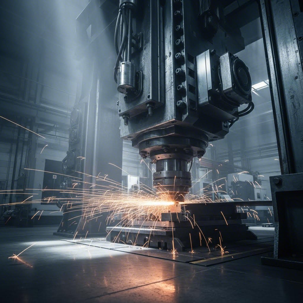
Ang metal stamping—tinatawag din na pressing—ay kasali sa paglalagay ng patag na sheet metal, maaaring nasa anyo ng coil o blank, sa loob ng isang stamping press kung saan ang isang tool at die surface ang nagbibigay ng hugis sa metal gamit ang mga teknik tulad ng punching, blanking, bending, coining, embossing, at flanging.
Kapag iniisip mo ang stamping sa praktikal na kahulugan, imahinahin mo ang pagpindot ng isang cookie cutter sa dough—maliban dito, ang "dough" ay bakal, aluminum, o tanso, at ang mga pwersang kasali ay maaaring umabot sa libong tonelada. Ang metal ay dumadaloy at lumalawak papasok sa die cavity, na permanenteng kumuha ng bagong hugis habang pinapanatili ang kanyang istruktural na integridad.
Bakit Dominado ng Stamping ang Modernong Pagmamanupaktura
Bakit naging pundasyon ng mataas na dami ng produksyon ang pamamaraang ito? Ang sagot ay nakasalalay sa tatlong mahahalagang pakinabang: bilis, pagkakapare-pareho, at kahusayan sa gastos.
Isipin ang industriya ng sasakyan, kung saan ang isang sasakyan ay mayroong daan-daang mga bahagi ng metal na nabubuhat sa pamamagitan ng stamping. Mula sa mga panel ng katawan hanggang sa mga bracket, ang mga tagagawa ay umaasa sa prosesong ito dahil ito ay nagbibigay ng:
- Hindi karaniwang bilis: Ang mga modernong press ay maaaring makumpleto ang anumang bilang mula 20 hanggang 1,500 na stroke kada minuto
- Kahanga-hangang pagkakapareho: Ang bawat bahagi ay tumutugma sa nakaraang bahagi nang may kahusayan na sinusukat sa mga bahagi ng millimeter
- Pang-ekonomiyang kahusayan: Kapag naistablish na ang tooling, ang gastos bawat yunit ay bumababa nang malaki sa mataas na dami
Bukod sa mga aplikasyon sa automotive, ang mga bahaging metal na nabubuhat sa pamamagitan ng stamping ay ginagamit din sa mga komponente ng aerospace, mga electronic device, kagamitang pang-medikal, at pang-araw-araw na paninda para sa konsyumer. Ang prosesong ito ay lubos na umunlad mula noong unang paggamit nito noong 1880s para sa mga bahagi ng bisikleta, at kalaunan ay pumilit sa mismong si Henry Ford na tanggapin ito kapag ang die forging ay hindi na kaya ng matugunan ang pangangailangan sa produksyon.
Tatlong Pangunahing Bahagi na Kailangan ng Bawat Stamping Operation
Ano ang isang operasyon sa pagpapadruk (stamping) nang wala ang mga pundamental nitong elemento? Ang bawat matagumpay na proseso ng pagpapadruk ay umaasa sa tatlong magkakaugnay na bahagi na gumagana nang sabay-sabay:
- Metal na Plaka (Ang Bahaging Gagawin): Ang hilaw na materyal—karaniwang bakal, aluminum, tanso, o bronse—ay dumadating bilang mga patong na bilog (coils) o mga pre-cut na blanko. Ang mga katangian ng materyal tulad ng likum (ductility) at lakas sa paghila (tensile strength) ay direktang nakaaapekto sa mga hugis na maaaring makamit.
- Die (Ang Kagamitan): Ito ay isang kagamitan na may mataas na presisyon na naglalaman ng negatibong imahe ng panghuling bahagi. Ang mga die ay maaaring mula sa simpleng disenyo na may iisang operasyon hanggang sa mga kumplikadong sistemang progresibo na may daan-daang estasyon.
- Press (Ang Pinagmumulan ng Lakas): Kung mekanikal man, hidrauliko, o servo-driven, ang press ay nagbibigay ng kontroladong puwersa na kailangan upang ipush ang metal papasok sa loob ng die cavity. Ang pagpili ng press ay nakabase sa mga salik tulad ng kinakailangang tonelada (tonnage), bilis ng stroke, at kumplikado ng bahagi.
Ang tatlong elementong ito ang bumubuo sa pundasyon na kailangan mong maunawaan habang tatalakayin natin nang detalyado ang bawat yugto ng pamamaraang ito sa pagmamanupaktura. Ang interaksyon sa pagitan ng pagpili ng materyales, disenyo ng die, at kakayahan ng press ang panghuling determinante kung magiging matagumpay o mabigo ang isang proyekto.
Buong Hakbang-hakbang na Paliwanag sa Workflow ng Stamping
Ngayon na nauunawaan mo na ang mga pangunahing bahagi, paano nga ba talaga nababago ang isang ideya patungo sa nakumpletong stamped part ? Ang proseso ng metal stamping ay sumusunod sa isang maingat na inorganisang serye kung saan ang bawat yugto ay nakabase sa nakaraang yugto. Kung palalampasin ang isang hakbang o mapapabilis ito, mahaharap ka sa mahal na pag-uulit ng gawa sa susunod na yugto. Tingnan natin nang buo ang proseso ng pagmamanupaktura ng stamping mula sa konsepto hanggang sa huling inspeksyon.
Mula sa Blueprint hanggang sa Nakumpletong Bahagi
Isipin ang proseso ng stamping tulad ng paggawa ng isang bahay—hindi mo ipapalagay ang pundasyon bago pa man tapusin ang mga disenyo ng arkitektura. Gayundin, ang mga matagumpay na proyektong stamping ay dumaan sa mga tiyak na yugto sa isang partikular na pagkakasunud-sunod:
- Konsepto at Pag-unlad ng Disenyo: Ang mga inhinyero ay nagtatrabaho kasama ang mga kliyente upang maunawaan ang mga pangangailangan sa pagpapatakbo, mga toleransya, at dami ng produksyon. Gamit ang software na CAD, nililikha nila ang detalyadong 3D na modelo at teknikal na mga drawing na tumutukoy sa bawat sukat.
- Pagpili ng materyal: Batay sa mga pangangailangan sa panghuling gamit ng bahagi, pinipili ng mga inhinyero ang pinakamainam na metal—na isinasaalang-alang ang mga kadahilanan tulad ng lakas, kakayahang pabagu-baguhin, paglaban sa korosyon, at gastos.
- Tooling at Disenyong Die: Ang mga presisyong die ay dinisenyo upang tumugma sa eksaktong mga tukoy na kinakailangan. Ang yugtong ito ang nagdedetermina kung ang bahagi ay maaaring talagang gawin ayon sa disenyo.
- Pagkakagawa ng Die: Ang mga bihasang tagagawa ng kagamitan ay gumagawa ng mga die gamit ang mataas na kalidad na tool steel, na kadalasan ay kasama ang CNC machining at EDM processes para sa katiyakan.
- Paggawa ng Prototype at Pagpapatibay: Bago ang buong produksyon, ginagawa ang mga sample na bahagi upang subukan ang die at patunayan na ang mga output ay sumusunod sa mga tukoy na kinakailangan.
- Paghahanda at Pagsasaayos ng Press: Ang mga operator ay nagsasagawa ng konpigurasyon sa stamping press gamit ang pinakamainam na mga parameter—haba ng stroke, bilis, presyon, at rate ng pagpapakarga.
- Gantimpalang Produksyon: Ang mga sheet o coil na gawa sa metal ay ipinapasok sa press, kung saan ang mga die ay nagbabago ng hilaw na materyales sa mga natatapos na bahagi nang mabilis.
- Pagsusuri ng kalidad: Bawat bahagi ay sinusuri sa pamamagitan ng pagsusuri sa sukat, pansariling pagtataya, at pagsubok sa pagganap upang matiyak ang pagkakapare-pareho.
- Mga Karagdagang Operasyon at Pagtatapos: Maaaring kailanganin ng mga bahagi ang karagdagang proseso tulad ng deburring, heat treatment, plating, o assembly.
Bakit ganito kahalaga ang pagkakasunod-sunod na ito? Dahil ang mga desisyon na ginagawa sa maagang yugto ay nakaaapekto sa buong proseso ng sheet metal stamping. Ang maling pagpili ng materyales ay nakaaapekto sa pagkasira ng die. Ang mahinang disenyo ng die ay nagdudulot ng mga depekto sa panahon ng produksyon. Ang hindi sapat na pag-setup ay nagdudulot ng hindi pare-parehong mga bahagi. Ang bawat yugto ay direktang nauugnay sa susunod na yugto.
Ang Mahalagang Yugto ng Disenyo at Inhenyeriya
Isipin ang paggawa ng mga kasangkapang pangbahay nang walang sukat—ito ang itsura kapag binibigyan ng mababaw na pansin ang yugto ng disenyo. Ayon sa RCO Engineering, ang pag-unlad ng produkto ay nagsisimula sa pagbuo ng konsepto ng huling produkto, kung saan kailangang magtulungan ang mga koponan ng disenyo at mga inhinyero sa paglikha ng mga detalyadong disenyo batay sa mga teknikal na tukoy.
Sa panahong ito, binibigyang-pansin ng mga inhinyero ang ilang mahahalagang elemento:
- Disenyo para sa Kakayahang Ma-produksyon (DFM): Ang mga bahagi ay ino-optimize upang maaaring i-stamp nang mahusay, na maiiwasan ang mga imposibleng hugis o labis na kumplikado.
- Pagsusuri sa Toleransiya: Tinutukoy ng mga inhinyero ang katanggap-tanggap na pagbabago sa sukat batay sa mga pangangailangan sa pagganap.
- Tukoy na materyal: Ang lakas, flexibility, at gastos ay lahat na nakaaapekto sa pagpili sa pagitan ng bakal, aluminum, tanso, o kobre.
- Mga Konsiderasyon sa Dami: Ang dami ng produksyon ay nakaaapekto kung ang progressive dies o ang mas simpleng compound dies ang mas makatwiran mula sa pananaw ng ekonomiya.
Tunay na nagsisimula ang proseso ng metal stamping dito—hindi kapag ang press ay nagsisimulang gumana. Ayon sa Sinoway Industry, ang paggamit ng pinakabagong CAD software upang lumikha ng detalyadong mga blueprint at 3D model ay nag-aaseguro na ang disenyo ng produkto ay na-optimize para sa parehong pagganap at kakayahang magawa.
Workflow ng Produksyon na Nag-aaseguro ng Pagkakapare-pareho
Kapag na-verify na ang tooling at na-configure na ang press, ang yugto ng produksyon ay nagpapalit ng hilaw na materyales sa natapos na mga bahagi. Ngunit ano nga ba ang talagang nangyayari sa isang karaniwang stamping cycle?
Isang karaniwang workflow sa produksyon ay kasama ang mga sumusunod na hakbang:
- Pagsasapak ng Materyales: Ang nakabaluktot na metal o mga pre-cut na blanko ay ipinapasok sa press, maaaring manu-manong o gamit ang mga awtomatikong sistema ng pagpapakain.
- Pasipikasyon: Ang materyales ay ina-advanse sa mga tiyak na lokasyon gamit ang mga pilot pin o mga sensor-guided na sistema.
- Paggawa ng Stamp: Ang press ram ay bumababa, na pumipilit sa materyales na pumasok sa loob ng die cavity kung saan ito tinutupad, binubend, o binubuo.
- Paglalabas ng Bahagi: Ang mga natapos na bahagi ay hinuhugot mula sa die at kinokolekta para sa inspeksyon.
- Pag-uulit ng Cycle: Ang proseso ay nagpapatuloy sa mga bilis na nasa pagitan ng 20 hanggang sa higit sa 1,000 strokes kada minuto, depende sa kumplikado ng bahagi.
Ginagamit ng mga inhinyero ang mga lubricant sa buong proseso ng stamping manufacturing upang bawasan ang friction at palawigin ang buhay ng tool. Ang mga cooling system ay tumutulong sa pagkalat ng init, lalo na sa mataas na bilis ng operasyon kung saan ang friction ay maaaring makaapekto sa kalidad ng bahagi.
Ang pagkontrol sa kalidad ay hindi naghihintay hanggang sa dulo. Ang mga operator ay nagsusuri ng mga parameter sa real-time, at ang istatistikal na sampling ay nakakakita ng mga pagkakaiba bago pa man ito maging malawakang problema. Ayon sa Aranda Tooling, ang ideal na provider ng serbisyo sa metal pressing ay kumikombina ng kagamitan, mga custom na kakayahan, at malawak na ekspertisya upang makamit ang mga layunin ng proyekto.
Ang pag-unawa sa buong workflow na ito ang nagpapaliwanag kung bakit mahusay ang stamping sa mataas na dami ng produksyon—kapag na-adjust na ang sistema, ito ay nagbibigay ng napakadakilang pagkakapare-pareho sa bawat bahagi. Ngunit anong uri ng press ang dapat gamitin para sa iyong tiyak na aplikasyon? Iyan ang sasagutin natin sa susunod.
Mga Uri ng Stamping Press at Kanilang Ideal na Aplikasyon
Kaya naisipan mo na ang disenyo ng iyong bahagi at na-plot ang workflow—ngunit aling stamping press ang dapat talagang mag-form ng iyong metal? Nakakalito ito sa maraming manufacturer dahil direktang nakaaapekto ang sagot sa bilis ng produksyon, kalidad ng bahagi, at pangmatagalang gastos. Tingnan natin nang buo ang tatlong pangunahing uri ng press upang makapili ka ng tamang makina para sa iyong tiyak na pangangailangan.
Ano nga ba ang stamping press sa kanyang pinakasentro? Ito ang kapangyarihan na nagbibigay ng kontroladong puwersa sa pindutin ang metal papasok sa mga die cavity . Ngunit hindi lahat ng stamping press ay gumagana sa parehong paraan. Ang bawat uri—mekanikal, hydraulic, at servo—ay gumagamit ng iba’t ibang mekanismo upang likhain at kontrolin ang puwersang iyon. Ang pag-unawa sa mga pagkakaiba na ito ay tumutulong sa iyo na maiwasan ang mahal na pagkakamali sa pagtutugma ng kagamitan at aplikasyon.
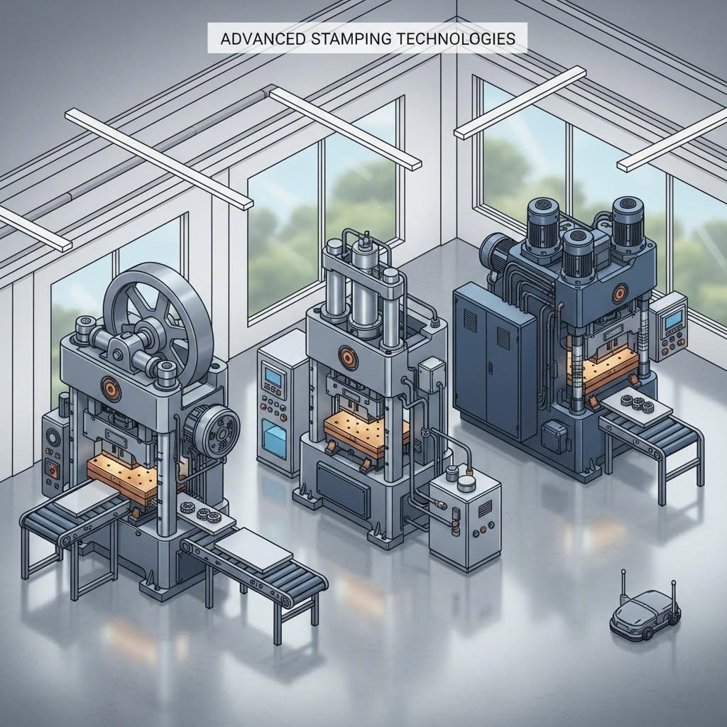
Mekanikal na Press para sa Mataas na Bilis na Produksyon
Kung ang bilis ang iyong pangunahing prayoridad, ang mga mekanikal na press ay kadalasang ang pinakamahusay na pagpipilian. Ginagamit ng mga makina na ito ang isang elektrikong motor upang makabuo ng enerhiya, na ipinapasa at inilalagay sa isang napakalaking flywheel. Ang flywheel na ito ang nagpapatakbo sa sistema ng punch-press sa pamamagitan ng isang crankshaft mechanism, na nagpapalit ng rotational na enerhiya sa linear na galaw na nagpapagalaw sa ram.
Bakit hinahangaan ng mga tagagawa ang mga mekanikal na metal stamping press para sa mataas na dami ng produksyon? Ang sagot ay nasa kanilang prinsipyo ng operasyon. Ang flywheel ay nag-iimbak ng rotational na enerhiya at nagpapalabas ng kontroladong bahagi nito upang magbigay-kapangyarihan sa mabilis at pare-parehong mga stroke. Ayon sa Sangiacomo Presses , ang mga mekanikal na press ay nakikilala sa kanilang kakayahang gumana nang mas mabilis kaysa sa mga servo press machine, na ginagawang lalo pang kapaki-pakinabang ang mga ito sa malalawak na operasyon kung saan ang bawat segundo ng produksyon ay mahalaga.
Ang mga pangunahing kabutihan ng mga mekanikal na stamping press ay kinabibilangan ng:
- Hindi karaniwang bilis: Ang patuloy na mabilis na mga siklo ay nagtitiyak ng mataas na output para sa mga paulit-ulit na gawain sa produksyon
- Katiyakan at tagal ng paggamit: Mga dekada ng naipakita nang mabuti ang teknolohiya kasama ang matibay na paggawa na nagpapababa ng mga hindi inaasahang pagkabigo
- Purong kapangyarihan: Ang mga rating ay karaniwang nasa pagitan ng 20 tonelada hanggang 6,000 tonelada, na kaya ang mga gawain na nangangailangan ng mataas na antas ng pagganap nang madali
- Cost-effectiveness: Mas mababang paunang pamumuhunan at mas simpleng pagpapanatili kumpara sa mga alternatibong servo
Gayunman, may mga limitasyon ang mga mekanikal na press. Nag-aalok sila ng nabawasang kakayahang umangkop sa haba ng stroke at profile. Ang flywheel ay tumatakbo nang tuloy-tuloy sa buong siklo ng press, na nagdudulot ng mas mataas na konsumo ng enerhiya. Sila rin ay karaniwang gumagana sa mas mataas na antas ng ingay, na maaaring mangailangan ng karagdagang mga hakbang sa kaligtasan sa lugar ng trabaho.
Mga Kawilihan ng Hydraulic Press sa Komplikadong Pagbuo
Kapag ang iyong aplikasyon ay nangangailangan ng bariablong lakas at kakayahang malalim na i-draw, ang mga hydraulic press ay sumisilip sa sentro ng atensyon. Ang mga makina na ito ay gumagana batay sa lubos na iba’t ibang prinsipyo—gamit ang presurisyadong hydraulic fluid imbes na isang kinetic na flywheel upang makabuo ng puwersa.
Ang pangunahing konpigurasyon ay binubuo ng dalawang konektadong silindro: isang malaking silindro na may mataas na dami ng likido na tinatawag na "ram" at isang mas maliit na silindro na may mababang dami ng likido na tinatawag na "plunger." Habang gumagalaw ang hydraulic fluid mula sa ram patungo sa plunger, ang panloob na presyon ay tumataas nang husto. Ayon sa Mga , ang sistemang ito ay kayang magbigay ng hanggang humigit-kumulang 10,000 toneladang puwersa para sa metal stamping.
Ano ang nagpapagawa ng isang steel stamping press na gumagamit ng hydraulic power na ideal para sa kumplikadong pagbuo? Isaalang-alang ang mga sumusunod na kapakinabangan:
- Buong puwersa sa buong stroke: Hindi tulad ng mga mekanikal na press na umaabot sa pinakamataas na puwersa sa tiyak na mga punto, ang mga hydraulic system ay nananatiling pare-pareho ang presyon
- Nakakagawa ng mahusay na deep drawing: Ang kontroladong at bariablong puwersa ay lubos na epektibo sa pagbuo ng mga kumplikadong cross-section
- Kahambaling paggamit sa mabibigat na materyales: Pinipili para sa pagtrato ng mas makapal o mataas na tensile strength na mga metal
- Adjustable force application: Ang mga operator ay maaaring i-adjust nang mahusay ang presyon batay sa mga kinakailangan ng materyal
Ano ang kompromiso? Ang mga hidraulikong press ay gumagana nang mas mabagal kaysa sa kanilang mga mekanikal na katumbas. Ngunit para sa mga aplikasyon na nangangailangan ng mga detalyadong metal na bahagi na inililipat o malaking dehormasyon ng materyal, ang pagkakapare-pareho at kakayahang umangkop ay karaniwang mas mahalaga kaysa sa bilis.
Teknolohiya ng Servo Press at Programable na Kontrol
Isipin ang pagsasama ng mekanikal na bilis at hidraulikong kumpas—ito ang pangunahing ibinibigay ng teknolohiya ng servo press. Ang mga advanced na makina na ito ay gumagamit ng mataas na kapasidad na servo motor sa halip na mga flywheel, na nagbibigay ng walang katulad na kontrol sa proseso ng paglilipat.
Ano ang nagpapahiwalay sa isang metal stamping press machine na may teknolohiyang servo? Ang servo motor ang direktang sumusubaybay at sumusuri sa galaw ng ram, na nagbibigay-daan sa real-time na pag-aadjust sa stroke at bilis batay sa gawain sa kamay. Ang software ang nagsisilbing kontrol sa motor, na nagpapahintulot sa mga pagbabago habang ginagawa ang gawain—mga kakayahan na hindi kayang gawin ng mga mekanikal na sistema.
Ayon sa Eigen Engineering, ang mga servo press ay mahusay para sa mga gawain na nangangailangan ng labis na katiyakan, tulad ng mga produkto sa elektronika, medikal, o mataas na kalidad na metal na mga bahagi na nabubuhat. Nagbibigay din sila ng mabilis na pag-aadjust sa setup, kaya sila ay perpekto para sa mga workshop na may paulit-ulit na pagbabago ng mga kinakailangan.
Ang mga pangunahing benepisyo ay kasama ang:
- Katumpakan at Kontrol: Mataas na programmable na stroke profiles na may adjustable na galaw, bilis, at posisyon sa anumang punto
- Kahusayan ng Enerhiya: Ang paggamit ng kuryente ay nangyayari lamang habang isinasagawa ang aktwal na pagbuhat, hindi patuloy
- Versatilidad: Kakayahang umangkop sa iba't ibang materyales, kapal, at mga kinakailangan sa pagbuhat nang walang pisikal na pag-aadjust
- Mas maikli ang oras para sa setup: Ang mga nakaimbak na programa ay maaaring agad na i-recall para sa mga kapaligiran ng produksyon na may mataas na variety ng mga produkto
- Kakayahang magbigay ng maximum na puwersa nang may kakayahang i-adjust: Kakayahang maglabas ng maximum na puwersa sa anumang punto sa loob ng operasyon
Ano naman ang mga kahinaan? Mas mataas na paunang puhunan at mas kumplikadong mga pangangailangan sa pagpapanatili. Ang mga makina na ito ay nangangailangan ng mga operator na may mas mataas na antas ng teknikal na ekspertise at espesyalisadong kaalaman sa parehong mekanikal at software na mga bahagi.
Paghahambing ng Mga Uri ng Press sa Isang Saglit
Ang pagpili sa pagitan ng mga opsyong ito ay nangangailangan ng pagsasaalang-alang ng maraming kadahilanan batay sa iyong tiyak na pangangailangan sa produksyon. Ang sumusunod na paghahambing ay tumutulong na linawin kung aling uri ng press ang umaayon sa iba’t ibang priyoridad sa operasyon:
| Factor | Mekanikal na press | Hydraulic press | Servo Press |
|---|---|---|---|
| Kakayahang Bilis | Pinakamataas (mabilis na tuloy-tuloy na mga siklo) | Pinakabagal (kontrolado at pantay) | Katamtaman hanggang Mataas (programable) |
| Alakhan ng Lakas | 20 hanggang 6,000 tonelada | Hanggang 10,000 tonelada | Nag-iiba depende sa modelo; buong lakas sa anumang punto ng stroke |
| Precision Level | Pantay ngunit nakafixed na profile | Magaling kasama ang variable control | Hindi karaniwan (buong-programang maaaring i-programa) |
| Konsumo ng Enerhiya | Mas mataas (pangpatuloy na operasyon ng flywheel) | Moderado | Mas mababa (paggamit ng kuryente ayon sa pangangailangan) |
| Pinakamahusay na Aplikasyon | Produksyon sa malaking dami at paulit-ulit; mga operasyon na progresibo at transfer | Malalim na pagguhit (deep drawing); mabibigat na materyales; kumplikadong paghuhubog | Produksyon na may maraming uri (high-mix); mga bahagi na nangangailangan ng katiyakan; komponente para sa elektronika at medisina |
| Unang Gastos | Mas mababa | Moderado | Mas mataas |
| Kumplikadong pagpapanatili | Payak | Moderado | Kumplikado (nangangailangan ng espesyalisadong ekspertis) |
Paano nakaaapekto ang pagpili ng press sa kalidad ng bahagi? Direkta ang ugnayan. Ang mga mechanical press ay nagbibigay ng pare-parehong resulta para sa mga simpleng at paulit-ulit na operasyon ngunit kulang sa fleksibilidad para sa mga kumplikadong hugis. Ang mga hydraulic system ay mahusay kapag ang mga bahagi ay nangangailangan ng patuloy na presyon o malaking daloy ng materyales. Ang mga servo press ay nag-aalok ng katiyakan na kailangan para sa napakapitik na toleransya at mga kumplikadong katangian.
Ang mga kinakailangan sa tonelada ay nakaaapekto rin sa iyong pagpili. Kung pipiliin mo ang isang press na kulang sa sukat, mahihirapan ka sa hindi kumpletong pagbuo o sa labis na pagsuot ng die. Kung naman ay pipiliin mo ang isang press na sobrang laki, mag-aaksaya ka ng kapital sa kakulangan ng paggamit ng kakayahan nito. Ang pagtutugma ng kakayahan ng press sa mga tiyak na kinakailangan ng iyong bahagi ay nagbibigay-daan sa optimal na resulta nang walang hindi kinakailangang gastos.
Matapos malinaw ang pagpili ng press, ang susunod na lohikal na tanong ay: anong mga teknik sa stamping ang gagawin ng mga makina na ito? Tingnan natin ang siyam na pangunahing paraan na nagbabago ng patag na metal sa mga gumagana nang bahagi.
Siyam na Pangunahing Teknik sa Stamping at Kung Kailan Dapat Gamitin ang Bawat Isa
Napili mo na ang iyong press at inilagay ang iyong workflow—ngunit alin sa mga teknik ng pagpapadim ang talagang bumubuo sa iyong bahagi? Ang sagot ay nakasalalay sa kung ano ang iyong gustong makamit. Bawat paraan ay nag-aapply ng puwersa sa iba't ibang paraan, na lumilikha ng magkakaibang resulta mula sa simpleng mga cutout hanggang sa mga kumplikadong three-dimensional na anyo. Tingnan natin ang siyam na pangunahing teknik na ginagamit araw-araw ng mga tagagawa, kasama ang mga prinsipyo ng inhinyero na nagpapagana sa bawat isa.
Bago tayo pumasok sa mga detalye, narito ang maikling buod ng mga teknik na tatalakayin natin:
- Blanking: Pagputol ng mga patag na hugis mula sa sheet metal upang lumikha ng mga workpiece
- Piercing: Pagpuputol ng mga butas at panloob na mga tampok sa mga sheet metal
- Pagpapaliko: Pagbuo ng mga anggulo at kurba kasalong isang linear na axis
- Coining: Paggamit ng labis na presyon upang lumikha ng maliliit na detalye at tiyak na mga sukat
- Pagpapahiwatig: Pagtaas o pagbaba ng mga pattern sa ibabaw ng metal
- Flanging: Pagbend ng mga gilid sa mga anggulo para sa assembly o pagpapalakas
- Paggagawa: Pagkuha ng metal papasok sa malalim na mga kuwadro upang lumikha ng mga balanseng hugis
- Progressive Die Stamping: Pagganap ng maraming operasyon nang sunud-sunod habang umuusad ang materyal sa pamamagitan ng mga istasyon
- Transfer Die Stamping: Paggalaw ng mga hiwalay na bahagi sa pagitan ng mga independiyenteng workstation
Ang pag-unawa kung kailan ilalapat ang bawat teknik—at ang pagkilala sa kanilang mga limitasyon—ang naghihiwalay sa mga matagumpay na proyekto mula sa mga mahal na kabiguan. Tingnan natin ang bawat paraan nang detalyado.
Blanking at Piercing para sa Mga Precise na Pagputol
Ano ang mangyayari muna kapag pumasok ang hilaw na sheet metal sa isang stamping operation? Karaniwan, ito ay pinuputol. Ang blanking at piercing ang dalawang pangunahing teknik sa pagputol, at bagaman pareho ang hitsura, iba-iba ang kanilang layunin.
Pagpuputol ay kasali sa pagputol ng patag na hugis mula sa mas malaking sheet—ang tinanggal na piraso ang naging iyong workpiece. Isipin ito tulad ng paggamit ng cookie cutter kung saan kinukuha mo ang cookie at itinatapon ang paligid na dough. Ayon sa Tuling Metal , ang blanking ang unang hakbang sa mga operasyon ng metal stamping, kung saan ang panlabas na profile ng stamped na komponente ng metal ay pinuputol para sa kaginhawahan. Ang halimbawang ito ng stamping ay gumagawa ng pundasyon para sa lahat ng susunod na forming operations.
Kapag nagpapadrukto ka ng mga metal na walang disenyo, ang prinsipyo ng inhinyero ay umaasa sa puwersang shear. Ang isang punch ay bumababa papasok sa isang tugmang die cavity, at ang metal ay nabibigat nang malinis kasabay ng cutting edge. Ang agwat sa pagitan ng punch at ng die—tinatawag na clearance—ay mahalaga sa kalidad ng gilid. Ang sobrang kakaunti na clearance ay nagdudulot ng labis na pagsuot sa tool; ang sobrang marami naman ay nagdudulot ng magaspang at may burr na mga gilid.
Pagbuho binabago ang proseso. Dito, ginagawa mo ang mga butas o slots sa sheet, at ang mga tinanggal na slugs ay naging scrap. Ang workpiece ay nananatiling ang sheet na may mga butas dito. Ang mga piercing tool ay karaniwang gumagamit ng high-carbon steel at nangangailangan ng regular na pagpapanatili upang mapanatili ang katiyakan ng pagputol. Kasali sa mga variant ang lancing (pagputol ng bahagyang outline), shaving (pagpapabuti ng kalidad ng gilid), at nibbling (paglikha ng mga kumplikadong hugis sa pamamagitan ng overlapping cuts).
Mga pangunahing isinasaalang-alang sa mga operasyon ng pagputol:
- Ang minimum na diameter ng butas ay dapat katumbas ng hindi bababa sa 1.2x na kapal ng materyal para sa mga ductile na materyales tulad ng aluminum
- Para sa mga mataas na tensilyong materyales tulad ng stainless steel, dagdagan ang minimum na diameter hanggang 2x ng kapal
- Ang espasyo mula sa gilid hanggang sa feature ay dapat panatilihin sa hindi bababa sa 2x ng kapal ng materyal upang maiwasan ang distorsyon
- Ang blanking ay nagbubunga ng magaspang na mga gilid na nangangailangan ng deburring o pangalawang pagpapaganda
Paghahambing ng mga Teknik sa Pagbending at Pagbuo
Kapag na-cut na ang iyong blank, ang pagbending ay nagpapalit sa patag na metal upang mabuo ang mga three-dimensional na hugis. Ngunit ang pagbending ay hindi isang teknik lamang—ito ay isang pamilya ng magkakaugnay na paraan, kung saan bawat isa ay angkop para sa partikular na aplikasyon.
Pamantayang pagbending ay naglalagay ng metal sa itaas ng isang die habang isang ram ay nangunguna sa blank upang makabuo ng ninanais na mga anggulo. Makakakita ka ng L-bends, U-bends, at V-bends depende sa geometry ng die. Ang hamon sa engineering? Ang springback. Ang metal ay may elastic component na nagdudulot ng bahagyang pagbalik patungo sa orihinal nitong hugis matapos maalis ang load. Ang mga ekspertong inhinyero ay nakakakompensa dito sa pamamagitan ng pagbending nang bahagya nang lampas sa ninanais.
Paghuhugas ng Hangin nag-aalok ng isang ekonomikal na alternatibo. Ang punch ay hindi ganap na umaabot sa die, kaya may natitirang puwang na hangin sa ilalim ng materyal. Ang paraan na ito ay nangangailangan ng mas mababang tonelada at inaalis ang pangangailangan ng tugmang tooling, ngunit mas mahirap na makamit ang mahigpit na toleransya. Ang kawastuhan ng anggulo ay nakasalalay sa eksaktong kontrol ng clearance.
Bottoming (tinatawag din na coining bending) ay pilitin ang sheet na pumasok nang buo sa isang V-die na may tamang sukat sa ilalim ng malakas na presyon. Hindi tulad ng air bending, ang bottoming ay gumagawa ng permanenteng at tumpak na mga baluktot na may kaunting springback lamang. Ang kapalit? Ito ay sumusuporta lamang sa mga V-shaped na baluktot at nangangailangan ng malakiang presyon ng press.
Flanging ang flanging ay nakatuon sa pagbabaluktot ng mga gilid ng maliit na workpiece sa mga kurbadong anggulo. Ang mga gilid na ito ay lumilikha ng mga punto ng koneksyon para sa pagkakabit ng mga assembly. Ang mga tagagawa ay umaasa sa flanging kapag kinakailangan ang mataas na kawastuhan sa kurbadong ibabaw.
Mga Mahahalagang Pagsasaalang-alang sa Pagbabaluktot:
- Ang pagbabaluktot ng matitigas na metal na may mababang plasticity ay may panganib na mag-crack—lalo na kapag ang mga baluktot ay tumatakbo nang parallel sa direksyon ng butil.
- Gawin ang pagkukurba matapos ang mga operasyon sa pagguhit upang maiwasan ang mga depekto dahil sa pagsisikip ng stress
- Panatilihin ang pinakamaliit na radius ng kurba na hindi bababa sa 0.5x kapal ng materyal para sa mga matalas na sulok
- Payagan ang 1-degree na toleransya sa pagbabago kapag ina-stamp ang mga 90-degree na anggulo
Pagpapadapa at Pagpapalitaw para sa Detalye ng Ibabaw
Kailangan mo ba ng mahihinang detalye, eksaktong sukat, o dekoratibong mga disenyong? Ang pagpapadapa at pagpapalitaw ay nagbibigay ng mga pagbabago sa ibabaw na hindi maisasagawa ng ibang teknik.
Paggawa ng barya kumakatawan ito sa pinakapresisyosong anyo ng cold-forming. Dalawang die ang nangungurakot sa sheet metal mula sa parehong panig nang sabay-sabay, na gumagamit ng labis na presyon na nagpapadaloy sa materyal papasok sa bawat detalye ng die. Kapag pinapadapa ang sheet metal, ang proseso ay nagbubunga ng mahihinang mga tampok na may kaunting paglipat ng materyal. Ang mga nabuong ibabaw ay nagpapakita ng mas mataas na paglaban sa impact at abrasion—na kung bakit ginagamit ang paraang ito sa aktwal na produksyon ng barya. Ang pagpapadapa sa bakal o iba pang metal ay karaniwang ginagawa bilang huling operasyon matapos matapos ang pangunahing pagbuo.
Pag-embos nagbibigay-daan sa paglikha ng mga pattern na nataas o nababawas sa ibabaw ng mga metal. Isang blankong sheet ang pinipindot laban sa isang die na may mga ninanais na pattern, kung saan inililipat ang mga disenyo na iyon sa workpiece. Ano ang resulta? Isang epekto ng tatluhang dimensyon na nagdaragdag ng visual na interes o mga tampok na pang-fungsiyon tulad ng mga pattern para sa grip. Ang aluminum ay lubos na epektibo sa mga aplikasyon ng embossing dahil sa kanyang mahusay na ductility at machinability.
Ano ang pangunahing pagkakaiba? Ang coining ay kinasasangkapan ng compression mula sa parehong panig kasama ang malaking daloy ng materyal, samantalang ang embossing ay karaniwang gumagana mula sa isang panig lamang upang lumikha ng surface relief.
Pagguhit para sa mga Balanseng at Malalim na Hugis
Paano nililikha ng mga tagagawa ang mga balangkang bahagi tulad ng mga baso, lata, o mga kahon? Ang mga operasyon ng drawing ay hinuhubog ang sheet metal papasok sa mga cavity ng die, na bumubuo ng mga hugis na tatluhang dimensyon mula sa patag na stock.
Pamantayang Pagguhit gumagamit ng isang punch na katumbas ng cross-section ng die. Habang bumababa ang punch, hinahatak nito ang sheet metal papasok sa lalim ng die, binubuo ang materyal ayon sa profile ng punch. Ang pamamaraang ito ng stamping at pressing ay gumagawa ng mga bahagi na may manipis na pader at di-regular na hugis, bagaman mas mababa pa rin ang katiyakan kumpara sa mga alternatibong deep drawing.
Deep drawing dine-develop pa ito. Dito, ang lalim ng hinugot na bahagi ay lumalampas sa kanyang diameter—nagkakamit ng ratio ng taas sa lapad na 2:1 o kahit 3:1. Ang pamamaraang ito ay gumagawa ng versatile na mga bahagi na may kumplikadong detalye at napakataas na katiyakan. Ang deep drawing ay isang cost-effective na alternatibo sa mga proseso ng turning para sa mga hollow cylindrical na bahagi.
Ang mga operasyon sa paghugot ay nangangailangan ng maingat na pansin sa:
- Lakas ng blank holder—ang kulang na presyon ay nagdudulot ng pagkukurba (wrinkling) dahil sa hindi pantay na daloy ng materyal
- Pangungulay—binabawasan ang friction sa pagitan ng mga ibabaw ng die at ng materyal
- Pagpili ng materyal—ang ductile na mga metal tulad ng aluminum at low-carbon steel ay mas madaling mahugot
- Maramihang yugto ng reduction para sa napakataas na depth ratio
Pagsasagawa ng Progressive Die Stamping para sa mga Komplikadong Bahagi
Ano ang mangyayari kung ang iyong bahagi ay nangangailangan ng maraming operasyon—tulad ng pagputol (blanking), pagpapasok ng butas (piercing), pagbubukod (bending), at pagbuo (forming)? Ang paggamit ng hiwalay na mga pagpasa sa iba’t ibang die ay nag-aaksaya ng oras at nagdudulot ng mga error sa pag-align. Ang progressive die at stamping ay naglulutas nito sa pamamagitan ng pagsasama-sama ng mga operasyon sa isang awtomatikong sunud-sunod na proseso.
Sa progressive stamping, ang isang metal na coil ay ipinapapasok sa isang serye ng mga estasyon sa loob ng isang set ng die. Bawat estasyon ay gumagawa ng tiyak na operasyon habang ang strip ay dumadaan. Ayon sa Larson Tool, ang progressive die ay idinisenyo para sa mataas na dami ng produksyon ng mga komplikadong bahagi, at gumagana sa pamamagitan ng sunud-sunod na mga estasyon kung saan bawat isa ay nagpapatupad ng tiyak na operasyon sa workpiece habang ito ay dumadaan sa press.
Ang kahanga-hangang inhinyerong gawa? Ang mga gabay na poste ay nag-aayos ng bawat operasyon nang eksakto, na nagtiyak ng katiyakan habang tumatagal ang metal na strip. Ang natapos na bahagi ay hihiwalayin mula sa carrier strip sa huling estasyon, samantalang isang bagong seksyon ay pumasok agad sa unang estasyon. Walang paghinto, walang muling pag-position—tanging tuloy-tuloy na produksyon lamang.
Kasali sa mga pakinabang ng progressive die:
- Awtomatikong tuloy-tuloy na operasyon nang walang pansariling interbensyon
- Eksaktong pag-aayos sa pamamagitan ng mga gabay na poste at pilot pin
- Produksyon na may mataas na bilis, na angkop para sa malalaking order ng mga paulit-ulit na bahagi
- Bawasan ang paghawak at ang kaugnay na mga panganib sa kalidad
Ano ang limitasyon? Mas mataas na paunang gastos sa tooling dahil sa kumplikadong disenyo ng multi-station die. Ang progressive die ay nangangailangan ng masinsinang pagpaplano at presisyong inhinyeriyang gawa, ngunit ang gastos bawat bahagi ay napapababa nang malaki kapag dumadami ang dami ng produksyon.
Transfer Die Stamping para sa Malalaking Komponente
Ang progressive stamping ay gumagana nang mahusay—hanggang sa ang iyong mga bahagi ay masyadong malaki o kailangan ng mga operasyon na hindi maaaring isunod nang linyar. Ang transfer die stamping ay tumutugon sa mga hamong ito sa pamamagitan ng paghihiwalay sa workpiece mula sa metal strip sa simula, imbes na sa dulo.
Sa mga operasyon ng transfer, ang mga mekanikal na sistema ang nagpapagalaw ng mga indibidwal na bahagi sa pagitan ng mga hiwalay na workstation. Hindi tulad ng progressive dies kung saan ang strip ang nagdadala ng mga bahagi pasulong, ang mga system ng transfer ay pisikal na inililipat ang bawat piraso. Ang paraang ito ay lubos na binabawasan ang basurang metal dahil walang carrier strip na nag-uugnay sa mga workstation.
Ang transfer die stamping ay nakasisiguro ng mahusay na produksyon ng:
- Mga malalaki o kumplikadong bahagi na hindi kasya sa mga limitasyon ng progressive die
- Mga komponenteng nangangailangan ng mga operasyon mula sa maraming anggulo
- Mga aplikasyon sa tube at deep-drawing
- Mga bahaging may threads, knurls, o knobs
Dahil ang mga sistema ng paglipat ay nagpapahintulot ng isang o higit pang hiwalay na die, ang mga gastos sa kagamitan ay maaaring talagang bumaba kumpara sa mga kumplikadong progressive setup. Gayunpaman, ang mga sopistikadong mekanismo ng paglipat ay nangangailangan ng regular na pagpapanatili upang maiwasan ang maling pag-align o mga depekto sa bahagi.
Cold Forming vs. Hot Forming: Mga Praktikal na Implikasyon
Karamihan sa mga operasyon ng stamping ay ginagawa sa temperatura ng kuwarto—ito ang cold forming. Ngunit kailan dapat isaalang-alang ang hot stamping sa halip?
Pagsasabog sa malamig kumakatawan sa karaniwang pamamaraan. Ang mekanikal na profile ng metal ay nananatiling pareho sa buong proseso. Kasama sa mga benepisyo ang mas simpleng kagamitan, mas mababang gastos sa enerhiya, at mahusay na surface finish. Gayunpaman, ang cold forming ay nangangailangan ng mas mataas na pwersa ng press dahil ang metal sa temperatura ng kuwarto ay mas tumututol sa deformation.
Pag-istilo ng init initininit ang metal bago ito nabuo, na nagbabago sa kanyang mikroestruktura. Sa mababang temperatura, ang mga kristal ng metal ay umiiral sa mas matitigas at higit na madudurog na mga oryentasyon. Ang pag-init ay nagpapalit sa kanila ng mas malambot at mas ductile na mga yugto—na binabawasan ang presyon na kailangan para sa dehormasyon. Pagkatapos ng pagbuo, ang pagpapalamig nang mabilis ng mainit na bahagi ay lumilikha ng istrukturang martensitic na nagdaragdag ng kahigpit at lakas.
Mga Praktikal na Implikasyon:
| Factor | Pagsasabog sa malamig | Pag-istilo ng init |
|---|---|---|
| Kailangang Lakas | Mas mataas | Mas mababa |
| Hugis ng ibabaw | Mahusay | Maaaring mangailangan ng pangalawang pagpoproseso para sa pagwawakas |
| Kapal ng materyal | Hanggang sa humigit-kumulang na 3 pulgada gamit ang espesyal na die | Mas angkop para sa mas makapal na mga materyales |
| Lakas ng Bahagi | Kasaganaan sa base na materyales | Maaaring paunlarin sa pamamagitan ng paggamit ng heat treatment |
| Konsumo ng Enerhiya | Mas mababa | Mas mataas (kinakailangan ang pag-init) |
| Kumplikado | Mas simple ang kontrol sa proseso | Nangangailangan ng pamamahala sa temperatura |
Ang hot stamping ay nakakagawa ng mga piyesa na sumisipsip ng enerhiyang may mataas na impact nang hindi nababali—kaya mainam ito para sa mga piyesa ng kaligtasan ng sasakyan. Ang cold forming ay nananatiling default para sa karamihan ng mga aplikasyon dahil sa pagiging simple at pagiging epektibo nito sa gastos.
Ang pagpili ng tamang pamamaraan—o kumbinasyon ng mga pamamaraan—ay nakasalalay sa hugis ng iyong bahagi, mga katangian ng materyales, at mga kinakailangan sa produksyon. Ngunit kahit ang perpektong pagpili ng pamamaraan ay hindi kakayanin ang mahinang pagpili ng materyales. Kaya naman, ang pag-unawa sa mga salik na may kinalaman sa stampability ay kasing-importante ng pag-master sa mga pamamaraan mismo.
Pagpili ng Materyales at mga Salik na May Kinalaman sa Stampability
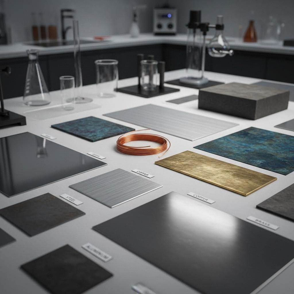
Nakamaster mo na ang mga teknik—ngunit kayang-harapin ba ng iyong piniling materyal ang mga ito? Ang tanong na ito ang naghihiwalay sa mga matagumpay na proyekto ng pagpaprisma mula sa mga mahal na kabiguan. Ang pagpili ng maling materyal para sa pagpaprisma ng metal ay nagdudulot ng mga bahagi na may butas, labis na pagsuot sa die, at mga pagkaantala sa produksyon na kumakain sa iyong kita.
Isipin ang stampability bilang "kalooban" ng isang materyal na ma-form. Ang ilang mga metal ay madaling dumaloy papasok sa mga kumplikadong hugis, samantalang ang iba ay tumututol sa pagbabago ng anyo o sumisira sa ilalim ng stress. Ang pag-unawa sa mga katangiang ito ay tumutulong sa iyo na piliin ang tamang metal para sa stamping batay sa iyong partikular na pangangailangan—na may balanseng pagtingin sa formability, lakas, gastos, at pagganap sa huling gamit.
Mga Grado ng Bakal at Kanilang Mga Katangian sa Stamping
Ang bakal ay nananatiling pangunahing materyal sa pagpaprisma ng metal, ngunit hindi lahat ng grado ng bakal ay may parehong pagganap. Ano ang pangunahing nagpapakilala sa kanila? Ang nilalaman ng carbon at mga elemento ng alloy.
Low carbon steel (0.05% hanggang 0.3% na carbon) ay nag-aalok ng mahusay na pagkabuo at kahusayan sa gastos. Ayon sa Pans CNC, ang mga bakal na may mababang carbon ay nagbibigay ng magandang kakayahang mapag-solder, likhaw (ductility), at lakas sa paghila (tensile strength) habang pinapanatili ang kahusayan sa gastos. Ang karaniwang mga grado tulad ng 1008, 1010, at 1018 ay kaya ang malalim na pagguhit (deep drawing), pagpapaluwali (bending), at mga operasyon gamit ang progressive die nang walang pumuputok o sumisira. Ano ang kompromiso? Ang mas mababang kahirapan (hardness) at kalagayan na madaling ma-corrode ay nangangailangan ng mga protektibong coating para sa maraming aplikasyon.
Stainless steel metal stamping nagdaragdag ng chromium, nickel, at molybdenum upang makabuo ng mga alloy na tumutol sa corrosion. Ang 300 series (austenitic) ay nag-aalok ng napakagandang pagtutol sa corrosion at likhaw (ductility), ngunit may mataas na rate ng work-hardening—ibig sabihin, ang materyal ay nagiging mas matigas at mas tumututol sa deformasyon habang ginagamit ito. Ang 400 series (ferritic) naman ay nagbibigay ng magandang kakayahang mapag-buo kasama ang mas mababang rate ng work-hardening, kaya ito ay angkop para sa mga aplikasyon kung saan mahalaga ang pagtutol sa corrosion ngunit hindi kailangan ang labis na likhaw.
Mga pangunahing isinasaalang-alang sa pag-stamp ng stainless steel:
- ang 304 stainless steel ay nagbibigay ng tensile strength na ≥515 MPa kasama ang mahusay na resistensya sa salt spray (≥48 oras)
- Kailangan ng mas mataas na pwersa sa pagbuo kumpara sa carbon steel—mag-expect ng 50% hanggang 100% na dagdag na tonelada
- Ang work hardening ay pabilis sa pagsuot ng die, kaya kailangan ng mas matitibay na mga materyales para sa tooling
- Ideal para sa kagamitan sa medisina, pagproseso ng pagkain, at mga terminal ng pag-charge para sa sasakyan
Galvanized steel pinagsasama ang pagkabuo ng carbon steel at ang proteksyon ng zinc coating. Kasama ang kapal ng zinc layer na ≥8 μm, ang mga materyales na ito ay nag-aalok ng pangunahing proteksyon laban sa rust sa mas mababang gastos kumpara sa mga alternatibong stainless steel. Ayon kay Tenral, ang galvanized steel ay angkop para sa mga bahagi ng istruktura kung saan mahalaga ang presyo at ang pangangailangan ng pansamantalang proteksyon laban sa rust, tulad ng mga chassis bracket para sa mga bagong sasakyang enerhiya at mga control panel ng appliance.
Mga Konsiderasyon sa Aluminum Stamping
Kapag mahalaga ang pagbawas ng timbang, ang aluminum stamping ay nagbibigay ng solusyon. Sa density na 2.7 g/cm³—halos isang ikatlo ng density ng bakal—ang mga stamped na bahagi ng aluminum ay malaki ang nagpapabaga sa timbang ng produkto nang hindi nawawala ang structural integrity.
Ngunit ang aluminum ay hindi isang solong materyales—ito ay isang pamilya ng mga alloy na may iba’t ibang katangian:
- serye 1100 (puri na aluminum): Mahusay na ductility para sa mga bahagi na malalim na inilalabas (deep-drawn); pinakamababang lakas
- 3003 at 5052: Magandang balanse ng lakas at stampability para sa pangkalahatang aplikasyon
- 5083:Mas mataas na lakas kasama ang mabuting resistance sa korosyon para sa mga aplikasyon sa dagat at istruktura
- 6061:Maaaring i-heat-treat para sa mga istruktural na stamped parts na nangangailangan ng mas mataas na lakas
Ayon sa LS Rapid Prototyping , ang aluminum ay nagbibigay ng mataas na mekanikal na lakas at mabuting electrical conductivity habang samantala ay resistant sa korosyon at hindi toxic. Hindi ito nangangailangan ng karagdagang coating sa panahon ng precision machining, bagaman ang anodizing ay nagpapaganda ng itsura at nagpapahusay pa ng resistance sa korosyon.
Ang aluminum stamping ay may mga hamon. Ang mas mababang tensile strength ng materyales (110–500 MPa depende sa alloy) ay nangangailangan ng maingat na pagmamasid sa mga limitasyon sa pagbuo. Ang galling—kung saan ang aluminum ay nakadikit sa ibabaw ng die—ay nangangailangan ng espesyal na lubricants at minsan ng mga surface treatment sa tooling.
Tanso at Bronse: Mga Pinuno sa Pagkakatutong Kuryente at Init
Kapag ang pagkakatutong kuryente o init ang nagpapagalaw sa iyong disenyo, dapat isaalang-alang ang pagpapakopya ng tanso at mga alternatibong materyales na gawa sa bronse.
Tanso nag-aalok ng pagkakatutong hanggang 98%, kaya ito ay hindi mapapalitan para sa mga electrical contact, busbar, at mga bahagi na responsable sa paglipat ng init. Ang mga grado tulad ng C101 at C110 ay nagbibigay ng mahusay na kakayahang pormahin para sa mga teknik ng cold forming. Ayon sa Tenral, madaling i-punch ang tanso upang makabuo ng micro-contact, kaya ito ay angkop para sa mga shrapnel ng SIM card at mga terminal ng wiring ng sensor sa industriya.
Ang likas na antimicrobial na katangian ng tanso ay nagdaragdag ng halaga para sa mga aplikasyon sa medisina at pagproseso ng pagkain. Gayunpaman, sa density na 8.9 g/cm³, ang timbang ay naging isang kadahilanan na dapat isaalang-alang para sa mga portable na produkto.
Tanso (aloy ng tanso at pilak) ay nagbibigay ng mas murang alternatibo kapag ang kawalan ng kailangang conductivity ng purong tanso ay hindi mahalaga. Ang H62 brass ay nagbibigay ng kahigpitang HB≥80 kasama ang mahusay na kakayahang maproseso—kadalasan ay walang pangalawang pagproseso ang kinakailangan pagkatapos ng stamping. Ang kanyang ductility ay nagpapahintulot sa pagbuo ng mga kumplikadong kurba at maliit na radius na mahirap gawin gamit ang iba pang materyales.
Ang mga stamping na gawa sa brass ay karaniwang ginagamit sa:
- Mga mekanismo ng smart door lock
- Mga sambungan ng automotive air conditioning
- Mga terminal at konektor sa kuryente
- Mga dekoratibong hardware at arkitektural na elemento
Paano Nakaaapekto ang mga Katangian ng Materyales sa Disenyo ng Die
Ang iyong pagpipilian ng materyales ay direktang nakakaapekto sa mga kinakailangan sa tooling. Ang pag-unawa sa ugnayang ito ay nakakaiwas sa mahal na di-pagkakatugma sa pagitan ng mga die at metal.
DUKTILIDAD sumusukat kung gaano kalaki ang pag-stretch ng isang materyal bago sumira. Ang mga materyal na may mataas na ductility tulad ng aluminum at brass ay kayang tumanggap ng mga agresibong operasyon sa pag-form. Ang mga metal na may mababang ductility ay nangangailangan ng mas malalaking bend radii at mas mahinahon na mga pagkakasunod-sunod sa pag-form upang maiwasan ang pagsira.
Lakas sa Pagpapahaba nagpapahiwatig ng pagtutol sa paghila palayo. Ang mga materyales na may mas mataas na lakas ay nangangailangan ng mas malaking presyon ng press at mas matitibay na materyales para sa die. Ang mataas na tensile strength ng stainless steel (≥515 MPa) ang paliwanag kung bakit ito nangangailangan ng malakiang dagdag na pwersa sa pagbuo kumpara sa mild steel.
Work Hardening naglalarawan kung paano lumalakas ang mga materyales habang binabago ang anyo nila. Ang austenitic stainless steels ay mabilis na nagkakaroon ng work-hardening—ang unang pagbuo ay ginagawang mas mahirap ang mga sumunod na pagbuo. Dapat isaalang-alang ng mga die ang tuloy-tuloy na paglakas na ito sa pamamagitan ng tamang clearances at pagkakasunod-sunod ng pagbuo.
Kapal nakaaapekto sa halos bawat aspeto ng disenyo ng die. Ang mas makapal na mga materyales ay nangangailangan ng mas malawak na die clearances, mas mataas na tonnage, at mas matitibay na konstruksyon ng tooling. Ang minimum na sukat ng mga feature ay nakakasukat nang proporsyonal—isang butas na angkop para sa 0.5 mm na aluminum ay hindi gagana sa 2 mm na steel nang walang mga pagbabago.
Paghahambing ng Materyales sa Isang Sulyap
Ang pagpili ng pinakamainam na materyales ay nangangailangan ng balanse sa ilang salik batay sa mga kinakailangan ng iyong aplikasyon. Ang paghahambing na ito ay nagbibigay ng buod ng mga pangunahing katangian upang gabayan ka sa iyong desisyon:
| Uri ng materyal | Lakas ng tensyon (MPa) | Kagubatan (g⁄cm³) | Rating sa Pagpapadruk | Mga Tipikal na Aplikasyon | Pangunahing Pagtutulak |
|---|---|---|---|---|---|
| Low carbon steel | ≥375 | 7.8 | Mahusay | Mga bracket para sa sasakyan, mga panel ng appliance, mga bahagi na pang-istraktura | Kailangan ng coating para sa proteksyon laban sa corrosion; pinakamura na opsyon |
| Stainless steel | ≥515 | 7.9 | Mabuti hanggang Katamtaman | Mga kagamitan sa medisina, pagproseso ng pagkain, mga terminal para sa pag-charge | Matataas ang panganib ng work hardening; nangangailangan ng 50–100% na dagdag na puwersa sa pagbuo |
| Aluminum | 110-500 | 2.7 | Mahusay | mga heat sink para sa 5G, mga kabalang elektroniko, mga bahaging pang-istraktura na magaan | May panganib na galling; inirerekomenda ang mga espesyal na lubricant |
| Tanso | 200-450 | 8.9 | Mabuti | Mga electrical contact, busbar, heat exchanger | Pinakamataas na conductivity; mas mataas na presyo ng materyales |
| Tanso | 300-600 | 8.5 | Mahusay | Mga konektor, dekoratibong hardware, mekanismo ng lock | Kost-epektibong alternatibo sa tanso; madaling ibuo ang mga komplikadong hugis |
| Galvanized steel | ≥375 | 7.8 | Mahusay | Mga bracket ng chasis, mga panel ng kontrol, mga bahagi ng istruktura | Pangunahing pag-iingat laban sa kalawang; maaaring magkaskas ang coating habang isinasagawa ang matinding pagbuo |
Ang tamang materyal ay hindi palaging ang pinakamalakas o pinakamahal—kundi ang umaayon sa iyong mga kinakailangan sa pagbuo, kapaligiran ng panghuling paggamit, at mga limitasyon sa badyet. Isang tunay na halimbawa sa mundo ng negosyo ang kumikilala nito nang perpekto: kapag kailangan ng isang kumpanya ng komunikasyon ng magaan na heat sink para sa 5G base station na may thermal conductivity na ≥150W/(m·K), ang purong tanso ay lumampas sa mga limitasyon sa timbang. Sa pamamagitan ng pagpili ng aluminum na 6061-T6 at precision stamping, nakamit nila ang mga target na timbang habang pinataas ang kahusayan sa pagkalat ng init ng 25% at binawasan ang gastos ng 18%.
Ang pagpili ng materyal ay nagtatatag ng pundasyon—ngunit kahit ang perpektong pagpili ng materyal ay hindi makakapantay sa mahinang tooling. Ang pag-unawa sa mga pundamental na prinsipyo ng die design ay nagtiyak na ang napiling materyal ay magiging de-kalidad na mga bahagi nang paulit-ulit.
Mga Pundamental na Prinsipyo sa Pagdidisenyo ng Die at mga Mahahalagang Kaalaman Tungkol sa Tooling
Napili mo na ang perpektong materyal at pinili na ang iyong paraan ng pagpapadruk—ngunit ano nga ba ang tunay na nagbibigay anyo sa metal na iyon upang maging mga bahagi na may kahusayan? Ang sagot ay nasa die (pandukha). Ang eksaktong disenyo nitong kasangkapan ay tumutukoy sa lahat, mula sa kalidad ng gilid hanggang sa kahusayan ng sukat, ngunit maraming tagagawa ang nakakaligtaan ang kritikal na kahalagahan nito. Ang pag-unawa sa mga steel stamping die (mga pandukhang bakal para sa pagpapadruk) at sa mga prinsipyo ng kanilang disenyo ang naghihiwalay sa mga operasyon na konstanteng matagumpay sa mga operasyon na puno ng mga isyu sa kalidad at hindi inaasahang pagkakatigil.
Isipin ang isang stamping die (pandukha para sa pagpapadruk) bilang ang DNA ng iyong natapos na bahagi. Ang bawat katangian, bawat toleransya, at bawat huling hawakan ng ibabaw ay umaabot pabalik sa paraan kung paano ito idisenyo, ginawa, at pinananatiling maayos. Ang isang mababang antas ng disenyo na die ay gumagawa ng basura. Ang isang maayos na idisenyong die na tumatakbo ayon sa tamang iskedyul ng pagpapanatili ay nagdudulot ng milyon-milyong identikal na bahagi. Tingnan natin kung ano ang nagbubukod sa dalawa.
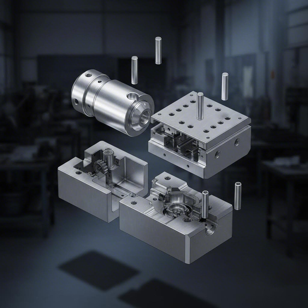
Mahahalagang Bahagi ng Die at Kanilang mga Tungkulin
Ano nga ba ang talagang nasa loob ng isang stamping machine para sa metal? Ang bawat die assembly—kung simple man o kumplikado—ay may mga pangunahing bahagi na nagtatrabaho nang sama-sama upang baguhin ang patag na sheet metal sa mga natapos na bahagi. Ayon sa Dynamic Die Supply, ang bawat bahaging ito ay may tiyak na tungkulin sa loob ng buong assembly:
- Die Block: Ang pambabae na bahagi ng die, na matatagpuan sa ilalim ng assembly. Ito ang naglalaman ng mga butas at mga tumutumbok na bahagi na kinakailangan para sa pagbuo ng materyal—sa madaling salita, ang kavidad na nagtatakda ng hugis ng iyong bahagi.
- Die Holder: Nagsusustento sa die block at nananatiling nakakapit sa bolster plate. Ang bahaging ito ay nagsisiguro na ang die block ay nananatiling eksaktong nakaposisyon habang isinasagawa ang mga operasyon na may mataas na puwersa.
- Punch: Ang pambabae na bahagi ng die na nagpapataw ng puwersa upang putulin o ibuo ang workpiece. Karaniwang ginagawa sa hardened steel o tungsten carbide, ang punch ay bumababa sa loob ng kavidad ng die block upang likhain ang ninanais na hugis.
- Punch Plate: Kung saan nakakabit ang bahagi ng pagpapalit, na pinapagalitan ng hydraulic o mekanikal na paraan. Ang plato na ito ay nagpapasa ng puwersa ng press nang direkta sa punch.
- Stripper plate: Inilalabas ang mga nabuo o pinutol na bahagi mula sa punch matapos ang bawat stroke. Kung walang tamang stripping action, mananatili ang mga bahagi sa tooling at magdudulot ng pagkakaharang sa produksyon.
- Mga gabay na pasak: Nag-aayos ng dalawang kalahati ng die nang may napakataas na kahusayan. Ang anumang pagkawala ng alignment—kahit sa mga bahagi ng millimetro—ay nagdudulot ng hindi pantay na pagsuot at mga error sa sukat.
- Mga Pad ng Presyon: Pinapanatili ang workpiece nang ligtas habang ginagawa ang pagputol o pagbuo. Ang tamang presyon ng blank holder ay nakakaiwas sa pagkukurba samantalang tinatayuan ang kontroladong daloy ng materyal.
- Mga Plate ng Presyon: Nagpapamahagi ng puwersa na ipinapadala ng punch nang pantay sa buong die assembly, upang maiwasan ang lokal na pagsisipol ng stress.
Paano isinasaalang-alang ng disenyo ng sheet metal stamping ang pagkakabuo ng mga komponenteng ito bilang isang buong sistema? Ang ugnayan sa pagitan ng clearance ng punch at die block—ang agwat sa pagitan ng mga gilid na pumuputol—ay direktang nakaaapekto sa kalidad ng gilid. Ayon sa Fictiv, ang tamang clearance ay nagpipigil sa labis na pagbuo ng burr at nagsisiguro ng malinis na pagputol, samantalang ang maling clearance ay nagdudulot ng magaspang na gilid at mas mabilis na pagkasira ng kagamitan.
Ang karaniwang pamamaraan ay nagtatakda ng die clearance sa humigit-kumulang na 5% hanggang 10% ng kapal ng materyal para sa karamihan ng mga metal. Ang mas manipis na materyales at mas malalambot na alloy ay gumagamit ng mas maliit na clearance; ang mas makapal o mas matitigas na materyales naman ay nangangailangan ng mas malawak na agwat. Ang pagkakamali sa pagkalkula ng balanseng ito ay nagdudulot agad ng mga problema sa kalidad—kung sobrang maliit ang clearance, lumalala ang pagkasira ng kagamitan, habang kung sobrang maluwang naman, nabubuo ang mga burr at hindi pare-pareho ang gilid.
Mga Materyales para sa Die na Nagpapahaba ng Buhay ng Kagamitan
Ang iyong stamping machine ay tumatakbo lamang hanggang sa magtagal ang iyong mga die. Ang pagpili ng angkop na materyales para sa mga die ang nagdedetermina kung ang tooling ay tatagal para sa libo-libong bahagi o milyon-milyong bahagi. Ang steel stamping machine na iyong binibigyan ng puhunan ay karapat-dapat na may mga die na inenginyero para sa gawain.
Ayon sa Gunna Engineering , ang tool grade steel na ginagamit para sa mga punch at die ay dapat na mas matigas at mas tumutol sa deformation kaysa sa workpiece na kinokontak nito. Higit pa rito, ang mga komponente ay dapat na tumagal sa daan-daang—marahil sa libo-libong—operasyon na may impact stress nang walang cracking, deformation, o chipping.
Ang mga tool steel ay dumaan sa mga tiyak na proseso ng heat treatment upang makamit ang mga katangiang ito. Ang base material—na isang coarse-grained alloy—ay nababago sa pamamagitan ng pag-init at quenching patungo sa hardened martensite. Ang carbon ay kumakalat sa loob ng grain structure, na bumubuo ng mga carbide na tumutol sa wear. Sa huli, ang tempering ay nagdaragdag ng resilience na kailangan upang maiwasan ang brittleness habang paulit-ulit na tinatamaan ng impact load.
Kabilang sa karaniwang mga grade ng tool steel para sa stamping machinery:
| Baitang | Mga pangunahing katangian | Pinakamahusay na Aplikasyon | Relatibong Gastos |
|---|---|---|---|
| D-2 | Matataas na paglaban sa pagsusuot, mabuting tibay, pagpapahigpit sa hangin | Mga dies para sa pagpuputol, mga punch para sa pagpapasok, produksyon na may mahabang takdang panahon | Moderado |
| A-2 | Nakapagpapahusay na tibay, katamtamang paglaban sa pagsusuot, pagpapahigpit sa hangin | Mga dies para sa pangkalahatang layunin, mga operasyon sa pagbuo | Moderado |
| O-1 | Mabuting kakayahang pagganap sa pagmamakinis, pagpapahigpit sa langis, ekonomikal | Mga kagamitang pansamantala, mga prototype na dies | Mas mababa |
| S-7 | Hindi karaniwang paglaban sa pagsalanta, mataas na tibay | Mabigat na pagpapakawala, mga operasyon na may mataas na impact | Mas mataas |
| M-2 (High-Speed) | Sobrang kahigpit at katatagan sa init | Mga progresibong die na high-speed, mga abrasive na materyales | Mas mataas |
Mga carbide inserts pataasin pa ang katatagan sa pagsuot. Ang tungsten carbide—na malinaw na mas matigas kaysa sa tool steel—ay nagpapahaba nang malaki ng buhay ng die kapag ginagamit sa pagpapadruk ng mga abrasive na materyales o sa paggawa ng napakaraming bilang. Ayon sa Fictiv, ang mga carbide insert ay pinipili para sa mga abrasive na operasyon o mahabang produksyon kung saan maaga ang pagsuot ng tool steel.
Ang mga elemento ng alloy sa tool steels ay nagbibigay ng mga tiyak na pakinabang sa pagganap:
- Tungsten at vanadium: Nagpapahusay ng katatagan sa pagsuot at pag-iingat ng talim
- Chromium: Nagpapabuti ng kakayahang mapahard at katatagan sa korosyon
- Molibdenum: Nagpapataas ng katibayan at lakas sa mataas na temperatura
- Nilalaman ng karbon: Nagtatakda ng mga antas ng kahigpitang maaabot
Mga Pamamaraan sa Pagpapanatili para sa Parehong Kalidad
Kahit ang pinakamainam na disenyo ng mga die na gumagamit ng de-kalidad na materyales ay nangangailangan ng sistematikong pagpapanatili. Ano ang naghihiwalay sa mga operasyon na nakakagawa ng milyon-milyong parehong bahagi mula sa mga operasyon na palaging nahaharap sa paulit-ulit na mga isyu sa kalidad? Ang proaktibong mga protokol sa pagpapanatili.
Ang tagal ng buhay ng die ay nakasalalay sa maraming magkasalungat na salik:
- Materyales na dinidisenyo: Ang mga abrasibo tulad ng stainless steel ay mas mabilis na pumipinsala sa mga die kumpara sa mild steel o aluminum
- Dami at bilis ng produksyon: Ang mas mataas na bilis ng stroke ay lumilikha ng higit na init at nagpapabilis ng pagsuot
- Mga pamamaraan sa paglalagay ng lubricant: Ang tamang paglalagay ng lubricant ay nababawasan ang friction, init, at pagkakagall
- Pagkakahanay ng press: Ang mga press na hindi naka-align nang maayos ay nagdudulot ng di-pantay na pagkasuot at maagang pagkabigo
- Pananatili ng clearance: Kapag sumusuot ang mga die, nagbabago ang mga clearance—na nakaaapekto sa kalidad ng gilid at sa katumpakan ng sukat
Ang epektibong mga programa sa pangangalaga ay kasama ang mga sumusunod na mahahalagang pamamaraan:
Mga regular na interval ng inspeksyon: Ang iskedyul na inspeksyon ng mga die ay nakakakuha ng pagkasuot bago pa ito makaapekto sa kalidad ng bahagi. Ang mga visual na pagsusuri ay nakakakilala ng pagkachip, pagkagall, o pinsala sa ibabaw. Ang mga pagsukat ng sukat ay nasisiguro na ang mga mahahalagang clearance ay nananatiling nasa loob ng mga tatakda.
Pagpapahusay ng talim at pagreregrind: Ang mga gilid na pangputol ay tumutulis sa paglipas ng panahon. Ang nakalaang pagpapalit ng gilid ay nagrerebisa ng katalasan bago maging problema ang mga burr.
Mga iskedyul para sa pagpapalit ng mga bahagi: Ang mga bahaging nagsisipag-us wear tulad ng mga stripper plate, guide pin, at mga spring ay may mga siklo ng buhay na madaling mahulaan. Ang pagpapalit ng mga bahaging ito ayon sa iskedyul ay nakakaiwas sa di-inaasahang pagkabigo habang nasa produksyon.
Mga tamang pamamaraan sa pag-iimbak: Ang mga die na hindi kasalukuyang ginagamit ay nangangailangan ng proteksyon laban sa corrosion at pisikal na pinsala. Ang pag-iimbak sa climate-controlled na lugar kasama ang mga rust-preventive coating ay nagpapahaba ng buhay ng mga tooling na hindi ginagamit.
Dokumentasyon at pagsubaybay: Ang pagre-record ng bilang ng stroke, mga gawain sa pagpapanatili, at mga obserbasyon sa kalidad ay lumilikha ng datos para sa paghuhula ng mga susunod na pangangailangan sa pagpapanatili. Ang sistematikong paraang ito ay nagbabago ng mga reaktibong pagkukumpuni sa mga nakalaang interbensyon.
Ang ugnayan sa pagitan ng pangangalaga sa die at kalidad ng bahagi ay direkta at nasusukat. Habang lumalabo ang mga clearance nang lampas sa tukoy na sukat, bumababa ang kalidad ng gilid—una sa pamamagitan ng kaunti lamang na pagtaas ng burr, at pagkatapos ay sa pamamagitan ng pagkalugmok sa dimensyon. Ang maagang pagtukoy sa mga pagbabagong ito sa pamamagitan ng regular na pagsukat ay nakakapigil sa pagpapadala ng mga bahaging hindi sumusunod sa mga kinakailangan.
Ang pag-unawa sa mga uri ng die ay nagdaragdag ng isa pang dimensyon sa mga desisyon sa disenyo ng stamping. Ayon sa Dynamic Die Supply, ang mga die ay nahahati sa tatlong pangunahing kategorya:
- Mga simpleng die: Gumagawa ng isang gawain bawat stroke, na perpekto para sa mga proseso na may mababang dami at iilan lamang ang hakbang
- Compound dies: Gumagawa ng maramihang operasyon sa pagputol bawat stroke, na angkop para sa mga kumplikadong disenyo
- Mga Kombinasyon na Die: Gumagawa ng parehong operasyon sa pagputol at pagbuo sa isang stroke, na nagpapabilis sa produksyon
Bawat uri ay nangangailangan ng iba’t ibang paraan ng pangangalaga. Ang mga progressive die na may maraming estasyon ay nangangailangan ng hiwalay na pansin sa bawat workstation. Ang mga transfer die ay nangangailangan ng pagsusuri sa mga mekanikal na sistema ng paghawak kasama ang kondisyon ng tooling.
Ang tamang disenyo at pangangalaga sa die ay nagtatag ng pundasyon para sa kalidad—ngunit kahit ang pinakamahusay na kagamitan ay maaaring magdulot ng depekto kapag ang mga parameter ng proseso ay lumiliko. Ang pagkilala sa karaniwang mga problema sa stamping at sa kanilang mga ugat na sanhi ay nagsisiguro na ang iyong investisyon sa mataas na kalidad na kagamitan ay magbibigay ng pare-parehong resulta.
Karaniwang mga Depekto sa Stamping at Paano Iwasan Ang mga Ito
Ang iyong mga die ay perpektong idisenyo at ang iyong mga materyales ay maingat na pinili—kaya bakit pa rin nabibigo ang mga bahagi sa inspeksyon? Kahit ang pinakamatatag na operasyon sa stamping ay nakakaranas ng mga depekto na maaaring sirain ang mga iskedyul ng produksyon at dagdagan ang gastos. Ang pag-unawa sa mga sanhi ng mga problemang ito—at kung paano maiiwasan ang mga ito—ang naghihiwalay sa epektibong operasyon mula sa mga operasyong palaging nakikipaglaban sa mga isyu ng kalidad.
Ito ang katotohanan: ang mga depekto sa mga stamping na bahagi ay bihira nangyayari nang kusang-loob. Ang bawat problema ay nauuugnay sa mga tiyak na pangunahing sanhi na kasali ang mga katangian ng materyal, kalagayan ng mga kagamitan, o mga parameter ng proseso. Kapag nauunawaan mo ang mga ugnayang ito, ang pagtukoy sa problema ay naging sistematiko na imbes na puro haka-haka lamang. Tingnan natin ang pinakakaraniwang mga isyu na nakaaapekto sa mga steel na stamping na bahagi at mga metal na stamping na bahagi, kasama ang mga na-probekang estratehiya para sa pag-iwas dito.
Pagkilala sa mga Sanhi ng Pagkukurba at Pagkabura
Ang pagkukurba at pagkabura ay kumakatawan sa magkasalungat na dulo ng spectrum ng pagbuo—subalit pareho silang nagmumula sa hindi tamang balanse ng puwersa habang isinasagawa ang stamping.
Pagkakaroon ng mga sugat nangyayari kapag ang materyal ay lumiliyab nang di pantay, na lumilikha ng mga hindi ninanais na paitaas o alon sa natapos na bahagi. Ayon kay Leeline Pack, ang ilang mga kadahilanan ang nagdudulot ng depektong ito:
- Kulang na puwersa ng blank holder: Kapag ang mga pad na may presyon ay hindi sapat na humahawak sa workpiece, ang materyal ay dumadaloy nang walang kontrol papasok sa loob ng die cavity
- Maling disenyo ng die: Ang hindi tamang geometry o ang hindi sapat na draw beads ay nabigo sa pagkontrol sa daloy ng materyal
- Sobrang kapal ng materyal: Ang mas makapal na mga sheet ay tumututol sa pagyuko at maaaring magkabukol kaysa umunlad
- Mababang Paglalagay ng Lubrikante: Ang hindi pantay na distribusyon ng lubricant ay lumilikha ng mga hindi pare-parehong lugar ng friction
Ang mga estratehiya sa pag-iwas ay nakatuon sa pagkontrol sa daloy ng materyal. Ang pagtaas ng presyon ng blank holder ay pumipigil sa labis na paggalaw ng materyal. Ang pagdaragdag ng draw beads sa mga ibabaw ng die ay lumilikha ng mga hadlang na friction na nagreregula sa paraan kung paano papasok ang metal sa loob ng cavity. Ang pag-optimize ng geometry ng die ay nagsisiguro ng pantay na distribusyon ng stress sa buong proseso ng pagbuo.
Pagkabasag nangyayari kapag ang materyal ay umaabot sa labas ng kanyang mga limitasyon sa pagbuo, na nagdudulot ng mga punit sa mga bahagi ng precision stamping. Ang pangunahing mga sanhi ay kinabibilangan ng:
- Labis na strain: Ang deformation ng materyal ay lumalampas sa mga limitasyon ng ductility ng metal
- Mga sharp na die radii: Ang mga matalim na sulok ay nagpapasentro ng stress, na lumilikha ng mga punto ng kabiguan
- Kulang sa Pagpapadulas: Ang mataas na panlaban sa paggalaw ay nagpipigil sa makinis na daloy ng materyal
- Hindi angkop na pagpili ng materyal: Ang mga metal na may mababang ductility ay sumisira habang isinasagawa ang agresibong pagbuo
Ang pagpigil sa pagkakaburak ay nangangailangan ng balanseng aplikasyon ng puwersa at kakayahan ng materyal. Ang pagpili ng mga metal na may angkop na elongation properties—mas mataas na ductility para sa mga kumplikadong hugis—ay binabawasan ang panganib ng pagsira. Ang pagtaas ng radius ng die at punch fillet ay nagpapamahagi ng stress sa mas malawak na lugar. Ang tamang paglalagay ng lubricant ay nagpapahintulot sa materyal na dumaloy nang makinis nang hindi nakakabit.
Pangangasiwa sa Springback sa mga Nabuong Bahagi
Nakapagpabent mo na ba ng isang piraso ng metal at napansin mong bahagyang bumalik ito patungo sa orihinal nitong hugis? Iyan ang tinatawag na springback—at isa ito sa pinakamahirap na depekto na pangasiwaan sa mga operasyong presisyong stamping.
Ang springback ay nangyayari dahil ang mga metal ay may elastikong bahagi kasama ang kanilang plastikong dehormasyon. Kapag nawala ang presyon sa pagbuo, ang elastikong bahagi ay bumabalik, na nagdudulot ng pagkakaiba ng bahagi mula sa ninanais na hugis. Ayon kay Leeline Pack, ang mga mataas na lakas na materyales ay nagpapakita ng malaking springback dahil sila ay may mas maliit na pagkakaiba sa pagitan ng yield strength at tensile strength kumpara sa mga bakal na may mas mababang lakas.
Mga kadahilanan na nakaaapekto sa kalubhaan ng springback:
- Mga katangian ng materyal: Ang mga metal na may mas mataas na lakas ay nagpapakita ng mas malaking elastikong pagbabalik
- Bend Radius: Ang mas mahigpit na mga baluktot ay lumilikha ng higit na residual stress at mas malaking springback
- Kapal ng Materyal: Ang mas makapal na mga sheet ay nag-iimbak ng higit na elastikong enerhiya
- Bilis ng pormasyon: Ang mas mabilis na operasyon ay maaaring hindi magbigay ng sapat na oras para sa kumpletong plastikong dehormasyon
Mga epektibong estratehiya para sa kompensasyon ng springback:
- Over-bending: Idisenyo ang mga die upang ibaluktot ang materyal nang lampas sa target na anggulo, na nagbibigay-daan sa springback upang marating ang ninanais na posisyon
- Bottoming: Ilapat ang karagdagang puwersa sa ilalim ng stroke upang maksimisinhin ang plastikong dehormasyon
- Mga tampok para sa pagbawas ng stress: Isama ang mga pampatibay na rip o mga palapag na nababawasan ang elastic recovery
- Pagsusuri ng Materyal: Kapag maaari, pumili ng mga alloy na may mas mababang ratio ng yield-to-tensile strength
Ang mga modernong CAE simulation tool ay nagpapahula ng springback behavior bago pa man gawin ang production tooling—na nagpapahintulot sa mga inhinyero na magkompensar nang maaga sa yugto ng die design imbes na sa pamamagitan ng mahal na trial-and-error na pag-aadjust.
Pigilan ang mga Surface Defects at Burrs
Ang mga problema sa surface quality—tulad ng mga burr, mga sugat, at deformation ng edges—ay direktang nakaaapekto sa parehong aesthetics at functionality ng mga stamped metal parts. Ang pag-unawa sa kanilang pinagmulan ay nagpapahintulot sa targeted na pag-iwas.
Burrs ay mga itaas na gilid o maliit na piraso ng metal na nananatili sa mga ibabaw na hinati. Ayon kay Leeline Pack, ang mga burr ay karaniwang dulot ng:
- Labis na pagkasira ng tool: Ang mga blangko o hindi talagang sharp na cutting edges ay kumukurap sa halip na malinis na i-shear ang materyal
- Hindi tamang die clearance: Ang mga agwat na sobrang lapad ay nagpapahintulot sa materyal na dumaloy sa pagitan ng punch at die
- Hindi naaayon na kagamitan: Ang hindi pantay na mga puwang ay nagdudulot ng hindi pare-parehong kondisyon sa pagputol
- Maling bilis ng press: Ang hindi angkop na bilis ng stroke ay nakaaapekto sa kalidad ng pagpuputol
Ang pag-iwas sa mga burr ay nangangailangan ng sistematikong atensyon sa kalagayan ng kagamitan. Ang regular na inspeksyon ay nakakadetekta ng pagsusuot bago masyadong maputol ang mga gilid. Ang pagpapanatili ng tamang clearance—karaniwang 5% hanggang 10% ng kapal ng materyal—ay nagtitiyak ng malinis na pagputol. Ayon sa DGMF Mold Clamps, ang paggamit ng alignment mandrels upang regular na suriin at i-adjust ang posisyon ng die ay nakakaiwas sa hindi pantay na mga pattern ng pagsusuot.
Mga scratch sa ibabaw karaniwang nagmumula sa:
- Maruruming ibabaw ng die: Mga chip ng metal o dumi na nakakapit sa pagitan ng kagamitan at ng workpiece
- Kulang na lubrication: Ang metal-to-metal na contact habang isinasagawa ang pagbuo ay nagdudulot ng mga marka ng friction
- Huwad na pagkakagawa ng die: Ang mga depekto sa ibabaw ay naililipat sa mga bahagi habang binubuo.
- Di-maayos na paghawak sa materyales: Mga sugat bago o pagkatapos ng stamping dahil sa hindi maingat na pagdadala.
Deformed Edges nagmumula sa mga puwersang kumikilos nang di pantay sa paligid ng bahagi. Ang pag-iwas dito ay kasama ang pagtiyak ng pantay na presyon ng blank holder, tamang pag-align ng die, at angkop na clearance sa buong cutting profile.
Talaan ng Depekto–Dahilan–Solusyon
Kapag may kaguluhan sa produksyon, ang mabilis na diagnosis ay nakakatipid ng oras at materyales. Ang talaang ito ay nagbibigay-buod ng pinakakaraniwang mga depekto na nakaaapekto sa mga bahaging naka-stamp nang may kahusayan, ang kanilang pangunahing dahilan, at ang na-probekang mga solusyon:
| Uri ng Defect | Pangunahing Sanhi | Mga Estratehiya sa Pag-iwas |
|---|---|---|
| Pagkakaroon ng mga sugat | Kulang na pwersa ng blank holder; di-maayos na geometry ng die; labis na kapal ng materyales; di-pantay na paglalapat ng lubricant | Pataasin ang presyon ng blank holder; magdagdag ng draw beads; i-optimize ang disenyo ng die; tiyaking pantay ang paglalapat ng lubricant |
| Pagkabasag | Labis na pagkakarga; matalas na mga radius ng die; hindi sapat na lubrication; mababang ductility ng materyal | Pumili ng mga materyal na may mas mataas na ductility; dagdagan ang mga radius ng fillet; mapabuti ang lubrication; bawasan ang severity ng forming |
| Springback | Elastic recovery sa mga materyal na may mataas na lakas; napakaliit na mga radius ng bend; makapal na materyales | Compensation para sa sobrang bending; teknik ng bottoming; idagdag ang mga feature para sa stress relief; isaalang-alang ang pagsasapalit ng materyal |
| Burrs | Nausog na mga cutting edge; hindi tamang clearance; hindi naka-align na tooling; hindi tamang bilis ng press | Regular na pagpapahusay ng tool; panatilihing tama ang mga clearance (5–10% ng kapal); i-verify ang alignment; i-optimize ang bilis ng stroke |
| Mga scratch sa ibabaw | Contamination sa die; hindi sapat na lubrication; rugad na ibabaw ng die; mahinang paghawak sa materyal | Linisin ang mga die nang regular; gamitin ang tamang lubricants; i-polish ang ibabaw ng die; ipatupad ang mga prosedurang pangangalaga sa materyal |
| Deformed Edges | Di-tumbok na presyon ng blank holder; hindi naka-align na die; hindi tamang clearances | Pangkalahatang pagkakapantay-pantay ng presyon; suriin at ayusin ang pagkakalign; i-verify ang mga clearance sa buong paligid |
| Hindi Tumpak na Dimensyon | Pagsusuot ng die; pagpalawak dahil sa init; pagbalik sa orihinal na hugis (springback); pagkakaiba-iba ng materyales | Regular na pagsusuri ng sukat; pagmomonitor ng temperatura; kompensasyon para sa pagbalik sa orihinal na hugis (springback); pagsusuri sa dumadaloy na materyales |
Paano Nakakaiwas ang Tamang Kontrol sa Proseso sa mga Isyu sa Kalidad
Ang pag-iwas sa depekto ay hindi tungkol sa pagharap sa mga problema nang hiwa-hiwalay—ito ay tungkol sa pagbuo ng mga sistema kung saan ang mga problema ay bihira mangyari. Tatlong magkakaugnay na salik ang nagdedetermina kung ang iyong mga stamped parts ay sumusunod nang pare-pareho sa mga espesipikasyon:
Disenyo ng mold itinatag ang pundasyon. Ang tamang mga clearance, angkop na mga radius, epektibong mga blank holder, at mataas na kalidad na materyales para sa die ay nakakapigil ng maraming depekto bago pa man ito magsimula. Ang pag-invest sa maayos na disenyo ng tooling ay nagdudulot ng malaking benepisyo sa buong produksyon.
Paggawa ng Pagsasanay sa Materyales dapat sumunod sa mga kinakailangan sa pagbuo. Ang pagpili ng mga metal na may angkop na ductility, pare-parehong kapal, at angkop na kalidad ng ibabaw ay nababawasan ang posibilidad ng mga punit, mga ugat, at mga depekto sa ibabaw. Ang pagsusuri sa dumarating na materyales ay nakakapulot ng mga pagkakaiba bago pa man pumasok sa produksyon.
Mga parameter ng proseso nag-uugnay ng lahat ng mga ito. Ang bilis ng press, puwersa ng blank holder, mga sistema ng lubrication, at kontrol ng temperatura ay lahat nakaaapekto sa kalidad ng bahagi. Ang dokumentasyon ng mga optimal na setting—kasama ang pagmomonitor para sa anumang pagkakaiba—ay nakakapulot ng mga problema bago pa man makagawa ng mga sirang produkto.
Ang pinakaepektibong mga operasyon ay nagkakasama ng mga elemento na ito kasama ang sistematikong pagmomonitor ng kalidad. Ang statistical process control ay sinusubaybayan ang mga pangunahing sukat sa paglipas ng panahon, upang matukoy ang mga trend bago pa man lumabas ang mga bahagi sa loob ng mga itinakdang espesipikasyon. Ang unang pagsusuri sa sample (first-article inspection) ay nagpapatunay na ang bawat run ng produksyon ay nagsisimula nang tama. Ang mga pagsusuri habang nasa proseso (in-process checks) ay nakakapulot ng mga isyu habang maaari pa itong ayusin.
Ang pag-unawa sa mga depekto at sa kanilang pag-iwas ay naghahanda sa iyo para sa produksyon—ngunit paano mo mapapatunayan na ang mga bahagi ay talagang sumusunod sa mga kinakailangan? Ang mga hakbang sa pagkontrol ng kalidad sa buong proseso ng stamping ang nagbibigay ng sagot.
Mga Hakbang sa Pagkontrol ng Kalidad sa Buong Proseso ng Stamping
Dinisenyo mo na ang mga kagamitan, pinili ang materyal, at in-optimize ang mga parameter ng iyong proseso—ngunit paano mo talaga malalaman kung ang mga bahagi mo ay sumusunod sa mga teknikal na tatakda? Ang pagkontrol ng kalidad ay hindi isang panghuli lamang na isipan sa produksyon ng stamping; ito ang sistema na nagpapalit ng mabubuting intensyon sa mga napatunayang resulta. Kung walang mahigpit na mga protokol sa pagsusuri, kahit ang pinakamalinaw na teknolohiya sa stamping ay magreresulta sa kawalan ng katiyakan imbes na kumpiyansa.
Isipin mo: isang depektoyong bahagi lamang sa isang sistema ng pagsasabog ng kotse o medikal na kagamitan ay maaaring magdulot ng malubhang kahihinatnan. Kaya naman, ang mga operasyon sa metal stamping sa produksyon ay nag-iinvest nang malaki sa mga sistemang pangkalidad na nakakadetekta ng mga problema nang maaga—nang ideal, bago pa man ito maging problema. Tingnan natin ang mga paraan ng pagsusuri, estadistikal na kasangkapan, at sertipikasyon ng industriya na naghihiwalay sa mga world-class na stamping operation mula sa iba.
Mga Paraan ng Pagsusuri ng Sukat
Paano mo sinusuri kung ang isang stamped na bahagi ay tumutugma sa kanyang blueprint? Ang pagsusuri ng sukat ang nagbibigay ng sagot sa pamamagitan ng mga teknolohiyang pagsukat na lumalawak ang kahirapan.
Mga Tradisyonal na Kasangkapan sa Pagsukat mananatiling pundamental. Ang mga caliper, micrometer, at height gauge ay nagpapatunay ng mahahalagang sukat nang may katiyakan na sinusukat sa libong bahagi ng isang pulgada. Ang mga coordinate measuring machine (CMM) ay lumalawak pa dito, na sinusuri ang maraming punto sa buong kumplikadong heometriya upang makabuo ng kumpletong dimensional profile. Ang mga pamamaraang ito na nakabase sa kontak ay nagbibigay ng maaasahang resulta para sa karamihan ng mga bahagi ng metal stamping.
Ngunit ano ang mangyayari sa mga kumplikadong kurba o mga tampok na hindi kayang abutin ng mga contact probe? Ayon sa Keneng Hardware, ang teknolohiya ng 3D scanning ay isa sa pinakamalaking pag-unlad sa pagsusuri ng metal stamping. Ang mga tradisyonal na pamamaraan ay madalas na gumagamit ng 2D na pagsukat, na maaaring palampasin ang mga maliit na pagbabago sa mga kumplikadong heometriya. Ang mga 3D scanner ay lumilikha ng detalyadong tatluhang dimensiyonal na representasyon ng mga stamped na bahagi, na nagpapahintulot sa komprehensibong pagsusuri ng hugis at sukat nang may di-nakikahalang katiyakan.
Kabilang sa mga modernong pamamaraan ng pagsusuri na ginagamit sa mga operasyon ng stamping:
- Coordinate Measuring Machines (CMMs): Mga programmable na sistema na sinusuri ang maraming punto para sa kumpletong pagpapatunay ng sukat
- 3D Laser Scanning: Teknolohiyang walang kontak na kumuha ng eksaktong data ng ibabaw nang mabilis para sa inspeksyon sa real-time
- Optical comparators: Itinatapon ang mga pinalaki na profile ng bahagi laban sa mga sangkabagay na sanggunian para sa biswal na pagpapatunay
- Mga Sistema ng Paningin na may AI: Mga awtomatikong kamera na nakikilala ang mga depekto sa ibabaw, pagkakaiba sa kulay, at napakaliit na mga kahinaan na maaaring makalusot sa obserbasyon ng tao
- Computer-Aided Inspection (CAI): Awtomatikong paghahambing ng mga sukat sa mga digital na modelo ng disenyo para sa mabilis na pagtukoy ng mga pagkakaiba
Ang mga toleransya sa automotive stamping ay kadalasang umaabot sa mahigpit na antas. Ayon sa Ang Tagagawa , ang dating ±0.005 pulgada ay ngayon karaniwang ±0.002 pulgada—at minsan ay kasing-hihigpit pa ng ±0.001 pulgada. Bukod dito, hinihiling ng mga customer ang capability indices (Cpk) na 1.33, na sa katunayan ay binabawasan ang gumagamit na toleransya sa kalahati. Ang pagkamit ng mga espesipikasyong ito ay nangangailangan ng matibay na konstruksyon ng die, kontroladong pag-unlad ng strip, at mga tooling na hindi lumalaban o lumalabas sa hugis habang tinatampok.
Non-Destructive Testing (NDT) ang mga paraan na ito ay nagsisilbing i-verify ang panloob na integridad nang hindi sinisira ang mga bahagi. Ang mga teknik na ito ay nakakatukoy ng mga nakatagong depekto na hindi makikita sa pamamagitan ng pagsusuri sa ibabaw:
- Ultrasonic Testing: Ang mga alon ng tunog ay nakakakilala ng mga depekto sa ilalim ng ibabaw at ng mga pagkakaiba sa materyales
- Pagsusuri Gamit ang Eddy Current: Ang elektromagnetikong induksyon ay nakakakilala ng mga pukyut, butas, o pagkakaiba sa komposisyon sa mga madaling magpasok ng kuryente na materyales
- Pagsusuri gamit ang magnetic particle: Nagpapakita ng mga pagkakahati sa ibabaw at malapit sa ibabaw sa mga ferromagnetic na materyales
Pangkontrol na Estadistikal ng Proseso sa Pagpapalipad
Mahusay ang pagkuha ng isang depektibong bahagi. Ngunit mas mainam pa ang pag-iwas na gawin ang anumang depektibong bahagi. Ang Pangkontrol na Estadistikal ng Proseso (SPC) ay binabago ang pokus ng kalidad mula sa pagtukoy patungo sa pag-iwas sa pamamagitan ng real-time na pagmomonitor sa pag-uugali ng proseso.
Ayon sa Keneng Hardware, ang pagpapatupad ng mga pamamaraan ng SPC ay nagpapahintulot sa mga tagagawa na mas epektibong subaybayan at kontrolin ang proseso ng metal stamping. Kasali sa SPC ang pagkuha at pagsusuri ng datos sa buong proseso ng produksyon upang matiyak na nananatili ang proseso sa loob ng mga itinakdang toleransya. Sa pamamagitan ng patuloy na pagsubaybay sa mga pangunahing parameter ng proseso, ang mga tagagawa ay maaaring agad na kumilos laban sa mga posibleng isyu at panatilihin ang mataas na antas ng kalidad.
Paano gumagana ang SPC sa praktika? Ang mga operator ay kumuha ng sample ng mga bahagi sa regular na mga panahon, sinusukat ang mga mahahalagang sukat, at inilalagay ang mga resulta sa mga control chart. Ang mga chart na ito ay nagtatakda ng upper at lower control limits batay sa likas na pagbabago ng proseso. Kapag ang mga sukat ay umaabot na sa mga limitasyon—o nagpapakita ng di-nakauugnay na mga pattern—ang mga operator ay kumikilos nang agad bago pa man lumabas ang mga bahagi sa itinakdang espesipikasyon.
Mga pangunahing konsepto ng SPC para sa mga operasyon ng stamping:
- Control Charts: Mga visual na display na sumusubaybay sa mga sukat ng dimensyon sa paglipas ng panahon, na nagpapakita ng katatagan ng proseso
- Kakayahang ng Proseso (Cp/Cpk): Mga indeks na sumusukat kung gaano kahusay ang pagganap ng proseso ayon sa mga limitasyon ng espesipikasyon
- Mga Patakaran sa Pagpapatakbo: Mga estadistikal na trigger na nagpapahiwatig ng di-random na pagbabago na nangangailangan ng pagsisiyasat
- Mga Plano sa Pagmimina: Mga sistematikong pamamaraan na tumutukoy sa dalas ng pagsusuri at laki ng mga sample
Pag-iinspeksiyon sa Unang Artikulo (FAI) ninunuo ang kahandaan ng produksyon bago magsimula ang buong pagpapatakbo. Ang komprehensibong pagsusuring ito ay nasisiguro na ang mga unang bahagi ay sumusunod sa lahat ng pangdimensional at pang-fungsyonal na kinakailangan—na pinapatunayan na ang pag-setup ng tooling, mga katangian ng materyales, at mga parameter ng proseso ay wastong nakauugnay. Ang FAI ay nahuhuli ang mga isyu sa setup bago pa man makagawa ng mga batch ng mga bahaging hindi sumusunod sa standard, kaya nakakatipid ito ng materyales at oras.
Ang mga sistemang pagsusuri sa loob ng linya ay higit na nagpapalawak sa pagmomonitor sa pamamagitan ng direktang integrasyon sa mga makina ng stamping. Ang mga sistemang ito ay nagbibigay-daan sa real-time na pagsusuri ng kalidad habang nangyayari ang produksyon, na agad na nakikilala ang anumang pagkakaiba at nagpapahintulot ng agarang pag-aadjust upang mapanatili ang pagkakapare-pareho.
Mga Sertipikasyon sa Industriya na Nagpapakita ng Kalidad
Paano ninyo sinusuri ang pangako sa kalidad ng isang potensyal na tagapag-suplay ng stamping? Ang mga sertipikasyon mula sa industriya ay nagbibigay ng obhetibong ebidensya na ang mga operasyon ay sumusunod sa mga kinikilalang pamantayan—lalo na ang kahalagahan nito sa mga aplikasyon ng automotive metal stamping kung saan ang mga kahihinatnan ng kabiguan ay napakagrabe.
Ayon sa NSF International , ang IATF 16949 ay ang internasyonal na pamantayan para sa mga sistemang pangkalidad sa automotive. Nagbibigay ito ng isang standardisadong Sistema ng Pamamahala ng Kalidad (QMS) na nakatuon sa pagpapalaganap ng tuloy-tuloy na pagpapabuti, na may diin sa pag-iwas sa mga depekto at sa pagbawas ng pagkakaiba-iba at basura sa supply chain at proseso ng pag-aassemble ng automotive.
Ano ang nagpapakita ng lubos na kahigpitan ng IATF 16949?
- Pokus sa Pagbabawal ng Depekto: Mga sistema na idinisenyo upang maiwasan ang mga problema, hindi lamang upang matukoy ang mga ito
- Pagbawas sa pagkakaiba-iba: Mga estadistikal na pamamaraan na nagpapababa ng pagkakaiba-iba ng proseso
- Patuloy na Pagpapabuti: Tuloy-tuloy na pagpapabuti ng mga sistemang pangkalidad at ng mga resulta nito
- Pamamahala ng supply chain: Ang mga inaasahang antas ng kalidad ay sumasaklaw din sa mga supplier at subcontractor
- Pag-iisip na batay sa panganib: Proaktibong pagkilala at pagbawas sa mga potensyal na isyu sa kalidad
Ang sertipikasyon sa IATF 16949 ay nagpapakita ng dedikasyon sa mga prinsipyong ito. Ayon sa NSF, karamihan sa mga pangunahing automotive Original Equipment Manufacturer (OEM) ay nangangailangan ng sertipikasyon sa IATF 16949 para sa kanilang supply chain. Ang mga organisasyon ay binabanggit ang mga benepisyo tulad ng pagpapabuti ng kasiyahan ng customer, pagtaas ng kahusayan, mas mahusay na pamamahala ng panganib, at mas napapalawak na access sa merkado.
Ang mga supplier na sertipiko sa IATF 16949 tulad ng Shaoyi ay nagpapakita ng dedikasyong ito sa kalidad sa pamamagitan ng mahigpit na sistema na nakakamit ng mataas na rate ng unang pag-apruba—ang Shaoyi ay nag-uulat ng 93% na unang pag-apruba sa pamamagitan ng kanilang komprehensibong mga protokol sa kalidad. Ang kanilang paggamit ng CAE simulation technology ay nagpapahintulot sa paghuhula ng mga depekto bago pa man gawin ang production tooling, kaya’t nahuhuli ang mga potensyal na isyu sa yugto ng disenyo imbes na sa production floor.
Bukod sa IATF 16949, ang iba pang nauugnay na sertipikasyon ay kasali ang:
- ISO 9001: Pundamental na sistema ng pamamahala ng kalidad na aplikable sa lahat ng industriya
- ISO 14001: Mga sistemang pang-pamamahala ng kapaligiran—na unti-unting kinakailangan ng mga automotive OEM
- ISO 45001: Pamamahala sa Kalusugan at Kaligtasan sa Trabaho
Ang mga pamantayan na ito ay may karaniwang Mataas na Istukturang Antas, na nagpapadali ng integrasyon. Ang mga operasyon na sertipikado para sa maraming pamantayan ay nagpapakita ng kumpletong katuruan sa pagpapatakbo ng sistema.
Mga Tumpak na Spesipikasyon at Pagkamit ng Toleransya
Ano ang mga toleransya na kayang abutin ng modernong automotive stamping? Ang sagot ay nakasalalay sa hugis ng bahagi, materyales, at antas ng kagalingan ng proseso—ngunit patuloy na umuunlad ang mga kakayahan nito.
Ang pagkamit ng mahigpit na toleransya ay nangangailangan ng pansin sa maraming kadahilanan. Ayon sa Ang Tagagawa , ang pagbawas ng pagkakaiba-iba sa sukat ay nakasalalay sa tatlong pangunahing kadahilanan: kapal ng die shoe upang maiwasan ang pagyuko habang isinasagawa ang stamping, sobrang laki ng die stops upang kontrolin ang konsistensya ng bawat hit, at malakas na guide pins upang tiyakin ang tumpak na pag-align.
Mga praktikal na gabay sa toleransya para sa mga stamped metal parts:
| Uri ng Feature | Pamantayang Toleransiya | Presisyong Tolerance | Mga pangunahing kadahilanan |
|---|---|---|---|
| Bilis ng Buhol | ±0.005 pulgada | ±0.001 pulgada | Linaw ng punch/die, kapal ng materyales |
| Lokasyon ng butas | ±0.010 pulgada | ±0.002 pulgada | Katiyakan ng pilot pin, kontrol sa strip |
| Kurbadong Anggulo | ±1° | ±0.5° | Kompensasyon sa springback, pagkakapareho ng materyal |
| Kabuuang sukat | ±0.010 pulgada | ±0.002 pulgada | Katiyakan ng die, kontrol sa temperatura |
| Katumpakan | 0.010 pulgada bawat pulgada | 0.003 pulgada bawat pulgada | Presyon ng blank holder, pagkakasunod-sunod ng pagbuo |
Ang mga napapanahong teknolohiya sa stamping ay nagpapahintulot nang mas dumarami sa katiyakan na dati lamang maabot sa pamamagitan ng machining—at sa bilis at kalamangan sa gastos na katangian ng stamping. Ang CAE simulation ay nagtataya ng pag-uugali ng pagbuo bago pa man umiiral ang pisikal na tooling, na nagbibigay-daan sa mga inhinyero na i-optimize ang mga disenyo para sa katiyakan ng sukat. Ang servo press technology ay nagbibigay ng programmable motion control na umaangkop sa mga pagbabago ng materyal sa totoong oras.
Ang pagsasama ng mahigpit na mga sistemang pangkalidad, napapanahong teknolohiyang pang-inspeksyon, at kontroladong proseso na nakatuon sa katiyakan ay nagpapahintulot sa mga operasyon sa pag-stamp na patuloy na tumutugon sa mga mahihigpit na espesipikasyon. Ngunit paano nga ba kumparahin ang pag-stamp sa iba pang mga paraan ng pagmamanupaktura kapag ang katiyakan, dami ng produksyon, at gastos ay lahat mahalaga? Ang ganitong paghahambing ang nagpapakita kung kailan talaga nagkikilabot ang pag-stamp—at kung kailan mas makatwiran ang iba pang mga pamamaraan.
Pagkukumpara ng Pag-stamp sa Iba Pang Mga Paraan ng Pagmamanupaktura
Nasakop mo na ang proseso ng pag-stamp—ngunit talaga bang angkop ito para sa iyong proyekto? Nararapat lamang na sagutin ang tanong na ito nang may katapatan. Bagaman naninigas ang pagmamanupaktura sa pamamagitan ng pag-stamp sa maraming sitwasyon, minsan ay nag-aalok ang iba pang mga pamamaraan ng mas mainam na resulta batay sa iyong tiyak na mga kinakailangan. Ang pag-unawa sa mga kompromiso na ito ay tumutulong sa iyo na gumawa ng mga balanseng desisyon na pinag-uugnay ang gastos, kalidad, at takdang panahon.
Isipin ang pagpili ng paraan ng paggawa tulad ng pagpili ng transportasyon. Ang mga kotse ay lubos na epektibo para sa karamihan ng mga biyahe, ngunit hindi mo gagamitin ang isang kotse para tumawid sa karagatan o para ilipat ang isang piano. Katulad nito, ang paggawa gamit ang metal stamping ay dominante sa ilang aplikasyon, samantalang ang iba pang proseso ay higit na epektibo sa ibang sitwasyon. Tingnan natin ang paghahambing ng mga opsyon upang makapagpasok ka ng tamang pamamaraan batay sa iyong pangangailangan.
Paghahambing ng Gastos: Stamping vs. CNC Machining
Ang desisyon sa pagitan ng stamping at CNC machining ay kadalasang nakasalalay sa isang kadahilanan lamang: ang dami ng produksyon. Parehong gumagawa ng mga bahagi ng metal na may mataas na kahusayan, ngunit ang kanilang istruktura ng gastos ay lubos na magkakaiba.
Ang CNC machining ay nag-aalis ng materyal mula sa solidong bloke gamit ang mga computer-controlled na cutting tools. Mababa ang puhunan sa setup—kailangan mo lamang i-upload ang CAD file at magsimula nang mag-cut. Dahil dito, ang machining ay perpekto para sa mga prototype at maliit na batch. Ayon sa Neway Precision, ang kada-yunit na gastos sa CNC machining ay kadalasang $5 hanggang $50 sa mababang hanggang katamtamang dami ng produksyon, kasama ang mababang hanggang katamtamang gastos sa setup.
Ang metal stamping at forming ay nangangailangan ng malaking paunang investment sa tooling—karaniwang $5,000 hanggang $50,000 depende sa kumplikasyon ng bahagi. Gayunpaman, kapag naibuild na ang mga die, ang gastos bawat bahagi ay napapababa nang husto. Ayon sa parehong sanggunian, ang mga stamped sheet metal parts ay maaaring bumaba sa ilalim ng $0.50 para sa mga simpleng hugis sa mataas na dami, na may average na gastos bawat yunit na nasa pagitan ng $0.30 at $1.50.
Saan nangyayari ang punto ng pagbabago? Ang kalkulasyon ay nakadepende sa iyong tiyak na bahagi, ngunit may pangkalahatang gabay na maaaring gamitin:
- Kulang sa 1,000 bahagi: Karaniwang nananalo ang CNC machining sa kabuuang gastos
- 1,000 hanggang 10,000 bahagi: Kailangan ng pagsusuri—ang kumplikasyon at materyales ang humuhugot sa desisyon
- Higit sa 10,000 bahagi: Ang stamping ay halos laging nagbibigay ng mas mababang kabuuang gastos
Mahalaga rin ang bilis. Ang high-speed stamping ay nakakamit ng cycle times na hanggang 0.06 segundo bawat bahagi—ang CNC machining ay hindi kayang abutin ang ganitong throughput. Sa steel stamping sa malaking saklaw, walang ibang proseso ang makakatumbok dito.
Mga Threshold ng Damihan para sa ROI ng Stamping
Kailan nababayaran ang investasyon sa proseso ng sheet metal? Ang pag-unawa sa mga threshold ng dami ay tumutulong sa iyo na magplano ng mga proyekto nang ekonomiko.
Ayon sa Neway Precision, ang stamping ay naging eksponenteng mas cost-effective sa mataas na dami dahil sa amortisasyon ng tooling at awtomasyon. Ang mga automotive OEM ay nakakatipid ng 20–30% sa unit cost gamit ang progressive stamping kumpara sa CNC machining para sa mga structural bracket.
Ganito gumagana ang ekonomiya: kung ipapamahagi ang $20,000 na gastos sa tooling sa 1,000 na bahagi, bawat bahagi ay magkakaroon ng $20 na bahagi ng gastos sa tooling. Kung ipapamahagi naman ang parehong investasyon sa 100,000 na bahagi, ang tooling ay magdaragdag lamang ng $0.20 bawat piraso. Kapag pinagsama na ito sa mababang gastos bawat cycle ng stamping, ang mataas na dami ay nagdudulot ng malaking pagtitipid.
Ang karagdagang mga kadahilanan ng kahusayan ay pinalalakas pa ang mga pakinabang na ito:
- Paggamit ng materyales: Hanggang 85–95% na yield na may optimal nesting, lalo na kapag ginagamit ang carbon steel at stainless steel
- Kahusayan sa Trabaho: Isang operator ang maaaring pangasiwaan nang sabay-sabay ang maraming press line
- Konsistensi: Mababang reject rate (sa ilalim ng 2%) sa mga awtomatikong stamping system na nagpapababa ng basura at rework
Kapag Ang Mga Alternatibong Paraan Ay Mas Makabuluhan
Mahalaga ang katapatan dito: ang pag-stamp ay hindi laging ang solusyon. May ilang senaryo kung saan mas mainam ang mga alternatibong pamamaraan sa paggawa.
Laser cutting plus forming angkop para sa mababang hanggang katamtamang dami ng produksyon na may katamtamang kumplikado. Ang gastos sa pag-setup ay napakaliit, at ang anumang pagbabago ay nangangailangan lamang ng mga update sa CAD imbes na bagong tooling. Ayon sa Neway Precision, epektibo ang pamamaraang ito para sa prototyping na may average na gastos kada yunit na $2 hanggang $10.
3D printing (DMLS/SLS) nakikilala sa paggawa ng mga kumplikadong hugis na imposibleng stampin. Kailangan mo ba ng mga panloob na channel, lattice structures, o organic shapes? Ang additive manufacturing ay gumagawa nito nang direkta. Ang kapalit? Napakataas na gastos kada yunit ($15 hanggang $100+) at mabagal na bilis ng produksyon—kaya limitado ang 3D printing sa mga prototype, tooling, o mga bahagi para sa mababang dami ng produksyon na may espesyal na aplikasyon.
PAGMOMOLDO tumutugon sa mga kumplikadong three-dimensional na hugis na nangangailangan ng maraming stamping operations at assembly. Para sa katamtamang hanggang mataas na dami ng produksyon ng mga intrikadong housing o bracket, maaaring mas ekonomikal ang casting kaysa sa mga stamped at welded assemblies.
Ayon sa Veco Precision ang stamping ay nag-aalok ng limitadong fleksibilidad para sa mga pagbabago sa disenyo, na maaaring magdulot ng karagdagang gastos sa tooling kapag may mga pagbabago. Ang mga proseso tulad ng electroforming ay nagbibigay ng mas mataas na fleksibilidad sa disenyo nang hindi nagdudulot ng dagdag na gastos dahil ang mga pagbabago ay maaaring maisagawa nang walang bagong tooling.
Paghahambing ng Paraan ng Pagmamanupaktura
Ang pagpili ng tamang pamamaraan ay nangangailangan ng pagsasaalang-alang sa maraming kadahilanan batay sa iyong partikular na mga kinakailangan. Ang paghahambing na ito ay naglalahad ng mga pangunahing kriteria sa pagdedesisyon:
| Factor | Panlililak ng sheet metal | Cnc machining | Laser Cutting + Forming | 3D Printing |
|---|---|---|---|---|
| Ideal na Saklaw ng Dami | Mataas (10,000+) | Mababa hanggang Medyo | Mababa hanggang Medyo | Prototyping hanggang Mababa |
| Gastos sa Pag-setup/Gastos sa Tooling | Mataas ($5,000–$50,000) | Mababa hanggang Medyo | Mababa | Wala hanggang Mababa |
| Presyo bawat Yunit sa Damihan | Napakababa ($0.30–$1.50) | Mataas ($5–$50) | Katamtaman ($2–$10) | Napakataas ($15–$100+) |
| Bilis ng produksyon | Napakabilis (hanggang 1,000 stroke/min) | Mabagal | Moderado | Sangdaling mabagal |
| Kumplikadong Anyo ng Bahagi | Maganda (2D na mga profile, mga baluktot, mga guhit) | Mahusay (anumang geometry na maaaring makinaan) | Moderado | Mahusay (mga panloob na tampok) |
| Kahatian sa Pagbabago ng Disenyo | Mababa (nangangailangan ng bagong kagamitan para sa paggawa) | Matataas (kailangan lamang ang pag-update ng CAD) | Mataas | Napakataas |
| Tagal ng Panahon para sa Unang Mga Bahagi | Mga Linggo (pagbuo ng kagamitan) | Araw | Araw | Mga oras hanggang araw |
| Pinakamahusay na Aplikasyon | Mga bracket, panel, at housing na may mataas na dami | Mga prototype at mga bahagi na may kumplikadong nakamaquinang mga tampok | Mga bahagi mula sa manipis na metal na may maikling produksyon | Mga kumplikadong prototype at kagamitan |
Balangkas ng Pagdedesisyon para sa Pagpili ng Paraan
Kapag sinusuri ang iyong proyekto, sagutin ang mga tanong na ito nang sistematiko:
- Ano ang dami ng iyong produksyon? Ang mga order na may wala pang 1,000 piraso ay karaniwang mas kinakabahala ang pagmamakinis o laser cutting. Ang mga order na higit sa 10,000 ay karaniwang nagpapaliwanag ng investasyon sa stamping tooling.
- Gaano katatag ang iyong disenyo? Ang madalas na pagbabago ay pabor sa mga flexible na pamamaraan. Ang mga na-lock na disenyo ay kumikinabang sa dedikadong kagamitan.
- Ano ang iyong timeline? Kailangan mo ng mga bahagi sa loob ng ilang araw? Ang machining o printing ang panalo. Nagpaplano ka ba para sa produksyon na tatagal ng buwan-buwan? Mag-invest ka sa stamping tooling.
- Anong geometry ang kailangan mo? Ang mga flat pattern na may mga bends at cutouts ay angkop para sa stamping. Ang mga kumplikadong 3D na hugis ay maaaring nangangailangan ng alternatibong pamamaraan.
- Ano ang istruktura ng iyong badyet? Ang mga proyektong may limitadong kapital ay maaaring piliin ang mga paraan na may mababang setup kahit mas mataas ang presyo bawat yunit.
Ang pinakamurang pamamaraan ay kadalasang kombinasyon ng iba’t ibang paraan. Gumawa ng prototype gamit ang machining o printing, i-validate ang mga disenyo sa pamamagitan ng maikling laser-cut na produksyon, at pagkatapos ay lumipat sa stamping para sa malalaking dami ng produksyon. Ang hakbang-hakbang na pamamaraang ito ay binabawasan ang panganib habang kinukuha ang ekonomiya ng dami ng stamping kapag angkop.
Ang pag-unawa kung saan ang tamang lugar ng stamping sa iyong manufacturing toolkit — at kung saan ang mga alternatibo ay mas angkop — ay nagpapahanda sa iyo upang maisagawa ang mga proyekto nang matagumpay mula sa simula.
Matagumpay na Pagpapatupad ng Iyong Stamping na Proyekto
Nakapaglakbay ka na sa buong proseso ng stamping—mula sa pag-unawa sa mga pundamental hanggang sa paghahambing ng mga alternatibong pamamaraan sa paggawa. Ngayon ay dumating ang praktikal na tanong: paano mo talaga isasagawa ang isang proyektong stamping? Ang tagumpay ay hindi nangyayari nang kusa. Kailangan nito ng sistematikong pagpaplano, may impormasyong pagdedesisyon, at estratehikong pakikipagtulungan na dadalhin ang iyong proyekto mula sa konsepto hanggang sa produksyon.
Isipin ang iyong proyektong stamping tulad ng paggawa ng isang bahay. Hindi mo sisimulan ang konstruksyon nang walang mga plano sa arkitektura, mga kinilalang kontratista, at malinaw na pag-unawa sa mga code sa paggawa ng gusali. Gayundin, ang matagumpay na mga operasyon sa metal pressing ay nangangailangan ng maingat na paghahanda sa maraming aspeto bago pa man mangyari ang unang pindot sa press.
Mga Pangunahing Salik para sa Tagumpay ng Proyektong Stamping
Ang bawat matagumpay na proyektong stamping ay may karaniwang pundasyon. Kung gagawa ka man ng mga bracket para sa sasakyan o mga kahon para sa elektroniko, ang mga salik na ito sa pagdedesisyon ang magtutukoy sa mga resulta:
- Pagkakatugma sa Pagpili ng Materyales: Ipagkasya ang mga katangian ng metal sa mga kinakailangan sa pagbuo at sa pagganap sa panghuling gamit. Isaalang-alang ang pagiging ductile para sa mga kumplikadong hugis, lakas para sa mga aplikasyon na may kinalaman sa istruktura, at paglaban sa korosyon para sa mga mapaghamong kapaligiran.
- Pagkakatugma ng Uri ng Proseso: Ang progressive die stamping ay angkop para sa mataas na dami ng mga kumplikadong bahagi. Ang transfer operations ay nakakahanap ng mas malalaking komponente. Ang simpleng dies ay gumagana para sa mga pangunahing heometriya sa mas mababang dami ng produksyon. Pumili batay sa heometriya ng iyong bahagi at sa dami ng produksyon.
- Mga Kinakailangan sa Press: Ang tonelada, bilis, at mga kakayahan sa kontrol ay dapat tugma sa iyong aplikasyon. Ang mekanikal na press ay nagbibigay ng bilis; ang hydraulic system ay nagbibigay ng kontrol sa puwersa; ang servo technology naman ay nag-aalok ng programable na kumpiyansa.
- Pagsunod sa Mga Pamantayan sa Kalidad: Tukuyin nang maaga ang mga kinakailangan sa toleransya. Ispesipiko ang mga paraan ng pagsusuri. Itakda ang mga kriterya sa pag-aproba bago simulan ang disenyo ng tooling—hindi habang nasa produksyon at nangyayari ang paglutas ng problema.
- Paghahanda sa Dami at Panahon: Ang pag-invest sa mga kagamitan para sa paggawa ay makabuluhan lamang sa angkop na dami ng produksyon. Ang mga mabilis na timeline ay nangangailangan ng mga supplier na may nakapagpapatunay na kakayahan sa mabilis na prototyping at may magagamit na kapasidad.
Ayon sa Eigen Engineering, ang tamang supplier ng mga bahagi para sa metal stamping ay tiyak na magpapanatili ng kalidad ng iyong produkto at maipapadala ito nang on time sa anumang proyekto sa pagmamanupaktura. Dahil maraming available na supplier, ang pagkilala sa isang custom metal stamping supplier na may kinakailangang ekspertisa at pamantayan sa kalidad ay naging isang mahalagang salik para sa tagumpay.
Pagpili ng Tamang Kasosyo sa Tooling
Ang iyong kagamitan at mga makina para sa metal stamping ay ganoon lamang ang epekto nito gaya ng antas ng kalidad ng mga die na ginagamit nila. Kaya naman, ang pagpili ng kasosyo sa tooling ay madalas na nagdedetermina kung magiging matagumpay o hindi ang isang proyekto.
Ano-ano ang dapat mong hanapin sa isang supplier ng die? Ayon sa Eigen Engineering, ang mga pangunahing kriteria sa pag-evaluate ay kinabibilangan ng:
- Karanasan na Nakatuon sa Partikular na Industriya: Ang mga supplier na pamilyar sa iyong industriya ay naiintindihan ang mga tiyak na toleransya at pamantayan sa kaligtasan. Ang ekspertisya sa aerospace at automotive ay nagpapahiwatig ng kakayahan para sa mga mahihirap na aplikasyon.
- Certifications: Ang IATF 16949 para sa automotive, ISO 9001 para sa pangkalahatang pamamahala ng kalidad, at AS9100 para sa aerospace ay nagpapahiwatig ng mga pamantayan at nasusuri nang maingat na proseso.
- Kakayahan sa In-House Tooling: Ang mga supplier na may panloob na disenyo at paggawa ng die ay maaaring mag-update ng mga pag-aadjust at bawasan ang gastos kumpara sa outsourcing ng tooling.
- Suporta sa engineering: Ang gabay sa disenyo para sa pagmamanupaktura (design-for-manufacturability) at mga kakayahan sa CAE simulation ay nakakadetekta ng mga problema bago pa man magastos ang paggawa ng tooling.
- Bilis ng prototyping: Ang mga kakayahan sa mabilis na paggawa ng prototype—kung saan ang ilang supplier ay nagdedeliver ng mga sample sa loob lamang ng 5 araw—ay nagpapabilis sa pagpapatunay ng disenyo at binabawasan ang oras papunta sa merkado.
- Mapag-ukol na Kapasidad sa Produksyon: Dapat bigyan ng pagkakataon ng mga partner ang iba’t ibang sukat ng order at makakasabay sa paglago ng iyong proyekto nang walang mga pagkaantala.
Ang komprehensibong mga partner sa tooling tulad ng Shaoyi ipakita ang mga kakayahan na ito sa pamamagitan ng sertipikasyon sa IATF 16949, advanced na CAE simulation para sa paghahProgno ng mga depekto, at mabilis na prototyping na may turn-around na maaaring umabot sa limang araw lamang. Ang kanilang 93% na first-pass approval rate ay sumasalamin sa mahigpit na mga sistema ng kalidad na nangunguna sa pag-iwas sa mga problema bago pa man ito mangyari—na eksaktong kailangan ng mga aplikasyong may mataas na pangangailangan.
Mahalaga rin ang komunikasyon. Ayon sa Eigen Engineering, ang bukas na komunikasyon ay mahalaga para sa maayos na pakikipagtulungan, lalo na sa mga kumplikadong proyekto na may mahigpit na mga deadline. Piliin ang mga supplier na nagpapanatili ng regular na mga update, nagkakomunikasyon tungkol sa mga timeline ng produksyon, at nananatiling transparent sa anumang potensyal na hamon.
Mga Susunod na Hakbang Mo sa Pagpapatupad ng Stamping
Handa ka na bang magpatuloy? Narito ang iyong konkretong roadmap para sa matagumpay na pagpapatupad ng isang proyektong stamping:
- Malinaw na Tukuyin ang mga Kailangan: Idokumento ang geometry ng bahagi, mga toleransya, mga espesipikasyon ng materyales, dami ng produksyon, at mga inaasahang timeline bago makipag-ugnayan sa mga supplier.
- Suriin ang Potensyal na Mga Kasosyo: Humiling ng mga presentasyon tungkol sa kakayahan. Magtanong tungkol sa mga sertipikasyon, kagamitan para sa metal stamping machine, at mga sistemang pangkalidad.
- Humiling ng Pagsusuri para sa Disenyo na May Pag-iisip sa Produksyon: Ibahagi ang mga CAD model para sa pagsusuri ng DFM. Ang mga ekspertong kasosyo ay nakakakilala ng mga posibleng isyu at nagmumungkahi ng mga pag-optimize upang mabawasan ang gastos sa tooling at mapabuti ang kalidad ng bahagi.
- Patunayan sa pamamagitan ng Prototyping: Gumawa ng mga sample na bahagi bago magpasiya sa produksyon ng tooling. Patnubayan ang mga sukat, subukan ang pagganap, at kumpirmahin ang pagganap ng materyales.
- Itatag ang mga Inaasahang Pamantayan sa Kalidad: Tukuyin ang mga paraan ng inspeksyon, mga plano sa sampling, at mga kriteria sa pagtanggap. Tukuyin ang mga kinakailangang sertipikasyon at dokumentasyon.
- Magplano para sa Produksyon: Kumpirmahin ang kapasidad, lead time, at logistics. Itatag ang mga protocolo sa komunikasyon para sa mga update sa produksyon at resolusyon ng mga isyu.
Ayon sa PMI , ang gumagana sa pagpapatupad ng stamping ay isang kombinasyon ng suporta mula sa mataas na antas at tiyak na mga pagsisikap—mga nakatuon na gawain ng mga indibidwal na may sapat na kaalaman sa mga kagamitan at pamamaraan, kamalayan sa kapaligiran, at dedikado sa pagbuo ng kinakailangang imprastruktura.
Ang biyahe mula sa hilaw na sheet hanggang sa natatapos na bahagi ay kasama ang maraming desisyon at walang bilang na detalye. Ngunit sa tamang pagpaplano, angkop na pagpili ng teknolohiya, at tamang mga pakikipagtulungan, ang stamping ay nagbibigay ng hindi maikakailang kahusayan para sa mataas na dami ng presisyong mga metal na komponente. Kung ikaw ay naglulunsad ng bagong produkto o nag-o-optimize ng umiiral na produksyon, ang mga prinsipyo na tinalakay sa buong gabay na ito ay nagsisilbing pundasyon para sa tagumpay.
Para sa mga tagagawa na handa nang pag-aralan ang mga solusyon para sa presisyong stamping die, ang mga katuwang na nag-ooffer ng komprehensibong kakayahan—mula sa suporta sa engineering hanggang sa produksyon ng mataas na dami—ay nagbibigay ng ekspertisya na kailangan upang maisakatuparan ang mga konsepto bilang de-kalidad na mga bahagi. Ang tamang pakikipagtulungan ay nagpapabaliwala sa mga kumplikadong kinakailangan at ginagawang simple ang pagsasagawa, na nagdudulot ng pare-parehong resulta na hinihiling ng iyong mga aplikasyon.
Mga Karaniwang Katanungan Tungkol sa Metal Stamping Process
1. Ano ang proseso ng stamping?
Ang proseso ng pag-stamp ay isang pamamaraan sa paggawa ng cold-forming na nagpapabago ng patag na sheet metal sa mga tiyak na hugis gamit ang mga die at press. Kasali rito ang paglalagay ng sheet metal sa isang stamping press kung saan ang mga ibabaw ng tool at die ay naglalapat ng kontroladong puwersa upang ipabago ang anyo ng metal nang hindi tinatanggal ang anumang bahagi nito. Ang mga pangunahing teknik ay kinabibilangan ng blanking, piercing, bending, coining, embossing, flanging, at drawing. Ang buong workflow ay sumasaklaw sa disenyo at inhinyeriya, pagpili ng materyales, paggawa ng die, pag-setup ng press, produksyon, at inspeksyon ng kalidad—na ginagawang ideal ito para sa mataas na dami ng produksyon sa mga industriya ng automotive, aerospace, at electronics.
2. Anu-ano ang 7 hakbang sa pamamaraan ng stamping?
Ang pamamaraan ng pagpapadruk ay karaniwang sumusunod sa mga hakbang na ito: (1) Pagbuo ng konsepto at disenyo gamit ang software ng CAD, (2) Pagpili ng materyales batay sa kakayahang mag-anyo at sa mga kinakailangan para sa panghuling paggamit, (3) Inhinyeriyang disenyo ng kagamitan at dies, (4) Pagkakagawa ng dies gamit ang mga proseso ng CNC machining at EDM, (5) Paglikha ng prototype at pagsusuri para sa pagpapatunay, (6) Pag-setup ng press kasama ang mga optimisadong parameter para sa haba ng stroke, bilis, at presyon, at (7) Produksyon kasama ang isinasama na inspeksyon ng kalidad. Ang ilang operasyon ay nagdaragdag ng sekondaryang pagwawakas bilang ikawalong hakbang. Ang mga supplier na sertipikado sa IATF 16949 tulad ng Shaoyi ay gumagamit ng CAE simulation sa panahon ng mga yugto ng disenyo upang mahulaan ang mga depekto bago pa man gawin ang produksyon ng mga kagamitan.
3. Paano isinasagawa ang stamping?
Ang stamping ay isinasagawa sa pamamagitan ng pagpapasok ng patag na sheet metal—sa anyo ng coil o blank—sa isang stamping press na may mga precision die. Ang ram ng press ay bumababa, na pumipilit sa punch na pumasok sa loob ng kavidad ng die block kung saan ang kontroladong presyon ay nagbibigay ng hugis sa metal sa pamamagitan ng mga operasyon tulad ng pagputol, pagbend, o pagbuo. Ang mga modernong mekanikal na press ay nakakamit ang 20 hanggang 1,500 strokes kada minuto, samantalang ang mga hydraulic at servo press ay nag-aalok ng variable force control para sa mga kumplikadong geometry. Ang tamang paglalagay ng lubrication ay nababawasan ang friction, ang mga guide pin ay nagsisiguro ng tamang alignment, at ang mga stripper plate ay inilalabas ang mga natapos na bahagi. Ang mga sistema ng kalidad, kabilang ang SPC monitoring at dimensional inspection, ay nagsisiguro na ang bawat komponente ay sumusunod sa mga nakatakda nitong specifications.
4. Ano-anong mga materyales ang karaniwang ginagamit sa metal stamping?
Kabilang sa karaniwang mga materyales para sa metal stamping ang mababang carbon steel (may mahusay na kakayahang pormahin at murang gastos), stainless steel (tumutol sa corrosion ngunit nangangailangan ng 50–100% na higit na pwersa sa pagporma), aluminum (magaan—isa lamang sa tatlong beses na densidad ng bakal), tanso (98% na electrical conductivity para sa mga contact), at brass (may mahusay na kakayahang iproseso para sa mga connector). Ang pagpili ng materyales ay nakabase sa stampability—ang kusa ng metal na pormahin—na isinasaalang-alang ang ductility, tensile strength, mga katangian ng work hardening, at kapal. Halimbawa, ang austenitic stainless steels ay mabilis na nagwo-work-harden, kaya kailangan ng mas matitigas na mga materyales para sa tooling at tamang clearances upang maiwasan ang cracking.
5. Kailan dapat piliin ang stamping kaysa sa CNC machining o iba pang pamamaraan?
Pumili ng stamping kapag gumagawa ng higit sa 10,000 bahagi kung saan ang investasyon sa tooling ay nababayaran sa pamamagitan ng malaki ang pagbaba ng gastos bawat yunit ($0.30–$1.50 kumpara sa $5–$50 para sa CNC machining). Ang stamping ay mahusay sa mataas na bilis na produksyon (hanggang 1,000 strokes kada minuto), na nakakamit ng 85–95% na paggamit ng materyales na may pare-parehong pag-uulit. Ang CNC machining ay angkop para sa mga prototype at mababang dami (mga 1,000 bahagi pababa) dahil sa napakababang gastos sa pag-setup. Ang 3D printing ay kaya ang mga kumplikadong panloob na heometriya na imposibleng gawin sa pamamagitan ng stamping. Isaalang-alang ang laser cutting para sa katamtamang dami na may madalas na pagbabago sa disenyo. Ang mga kasosyo tulad ng Shaoyi ay nag-aalok ng mabilis na prototyping sa loob ng 5 araw upang i-validate ang mga disenyo bago magpasiya sa produksyon ng tooling.