 சிறு கலைகள், உயர் தரம் தரவுகள். எங்கள் வேகமான மாதிரி செயற்படுத்தும் சேவை சரிபார்ப்பை வேகமாக்கும் மற்றும் எளிதாக்கும் —

தாவர தொழிலில் ஸ்டாம்பிங்: தற்போது துப்பாக்கி மற்றும் ஸ்பிரிங்பேக்கை குறைக்கவும்
நவீன வாகன உற்பத்தியை முத்திரையிடல் ஏன் வரையறுக்கிறது?
ஒரு புதிய மின்சார வாகனத்தின் நேர்த்தியான ஹூட் அல்லது பேட்டரி பேக்கை ஆதரிக்கும் சிக்கலான ஆதரவாக ஒரு தட்டையான எஃகு தாள் எவ்வாறு மாறுகிறது என்று எப்போதாவது யோசித்திருக்கிறீர்களா? இந்த மாயமானது ஒரு செயல்முறையின் மூலம் நிகழ்கிறது, இது உற்பத்தி மூலக்கல்லாக உள்ளது, இது அமைதியாக வாகன புரட்சியை இயக்குகிறது. ஆனால் வாகனத் தொழிலில் முத்திரை குத்துவது என்ன நாம் 2025-ம் ஆண்டுக்குள் செல்லும்போது இது ஏன் மிகவும் முக்கியமானது?
வாகனத் தொழிலில் முத்திரை குத்துவது என்றால் என்ன?
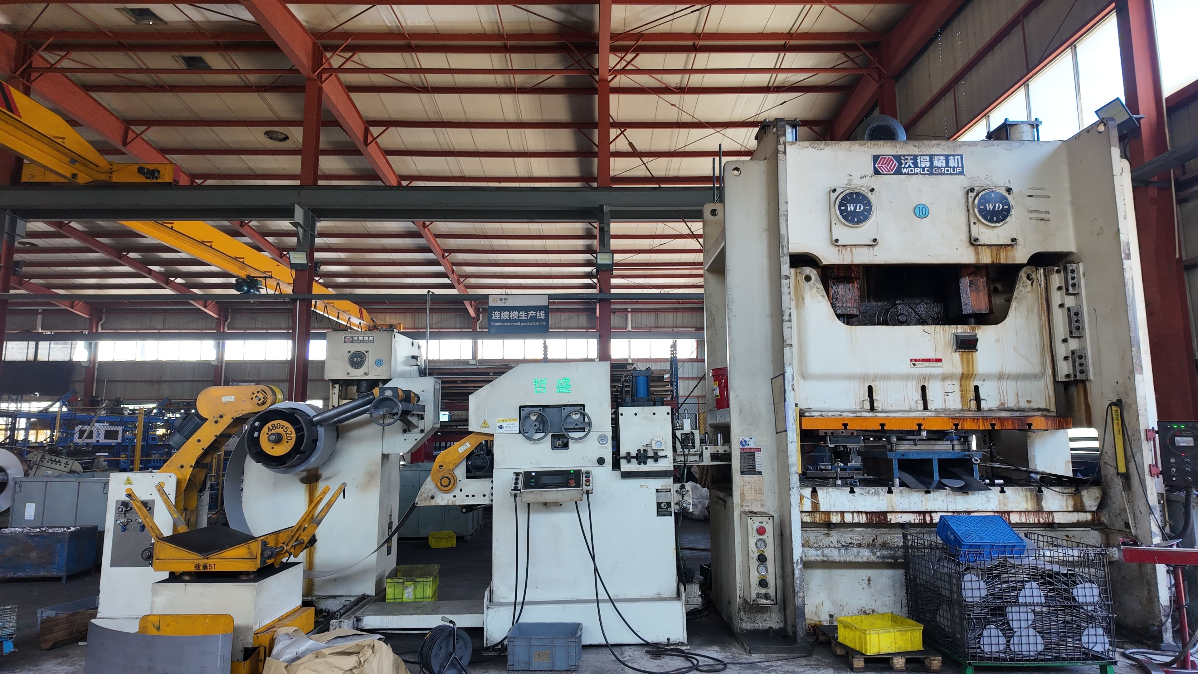
அதன் அடிப்படையில் வண்டி அறிமுகப்படுத்துதல் (சில நேரங்களில் கார் மெட்ல் சின்டிங் ) என்பது உலோகப் படலங்களை குறிப்பிட்ட வடிவங்களுக்கு வடிவமைப்பதற்கான அதிவேக மற்றும் உயர் துல்லியமான முறையாகும். வாகனத்திற்கு தேவையான எந்த வடிவத்திலும் வளைக்க, வெட்ட, உருவப்படக்கூடிய வலுவான அச்சுப்பொறிகள் மற்றும் தனிப்பயன் வடிவங்களை பயன்படுத்தி, ஸ்டாம்பிங் ஆலைகள். எனவே, ஸ்டாம்பிங் என்றால் என்ன இந்த சூழலில்? இது ஒரு செயல்முறையாகும். இதன் விளைவாக உருவாகும் பகுதியானது, உலோகத்தை ஒரு தட்டுடன், மிகப்பெரிய அழுத்தத்தின் கீழ், விரும்பிய வடிவத்திற்கு வலுப்படுத்தும்போது உருவாகிறது.
நவீன முத்திரை குத்துதல் என்பது வெறும் கரடுமுரடான வலிமை மட்டுமல்ல; அது துல்லியம், மீண்டும் மீண்டும் செய்யக்கூடிய தன்மை மற்றும் செயல்திறன் ஆகியவற்றைக் குறிக்கிறது. மேம்பட்ட ஆட்டோமேஷன் மற்றும் டிஜிட்டல் கட்டுப்பாடுகள் மூலம், இன்றைய முத்திரை செருகுதல் நிலையம் மில்லியன் கணக்கான ஸ்டாம்ப் செய்யப்பட்ட உலோகம் ஒவ்வொரு வருடமும் ஒவ்வொரு பாகங்களும் முந்தைய பாகங்களுடன் கிட்டத்தட்ட ஒரே மாதிரியானவை. இது சாலைகளில் செல்லும் ஒவ்வொரு காரின் பாதுகாப்பிற்கும், பொருத்தத்திற்கும், முடிவிற்கும் அவசியம்.
வாகன உற்பத்தி செயல்முறைக்கு முத்திரை குத்துதல் பொருந்தும் இடங்கள்
ஒரு கார், அதன் கருத்தாக்கத்திலிருந்து, அதன் காட்சி நிலையம் வரை செல்லும் பயணத்தை கற்பனை செய்து பாருங்கள். வடிவமைப்பு மற்றும் பொருள் தேர்வுக்குப் பிறகு ஸ்டாம்பிங் அமைக்கப்படுகிறது, ஆனால் உறைதல் மற்றும் இறுதி அசெம்பிளிக்கு முன். ஆட்டோமொபைல் முத்திரை குத்தலுக்கான எளிமைப்படுத்தப்பட்ட செயல்முறை வரைபடம் இங்கேஃ
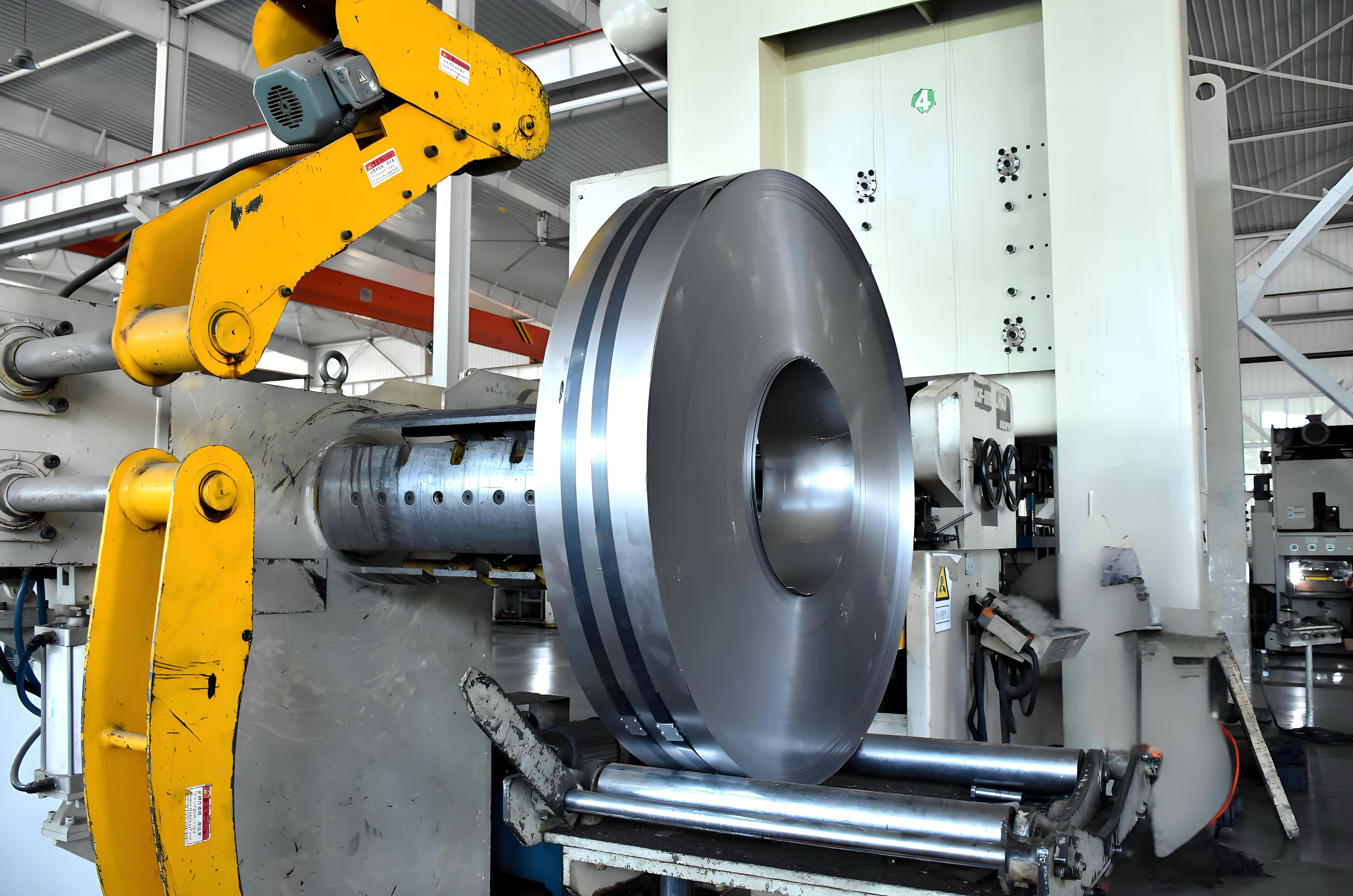
- பிளாங்கிங் தட்டையான தட்டு உலோகத்தை தொடக்க வடிவத்திற்கு (வெற்று) வெட்டுதல்
- ஃபார்மிங் வெற்றுப் பகுதியை 3D பகுதியாக வடிவமைக்க பிரஸ் மற்றும் மடிப்புகளைப் பயன்படுத்துதல்
- முறுக்கிக் கொள்வது மற்றும் துளைப்பது தேவையான அளவுக்கு கூடுதல் பொருளை அகற்றி, துளைகள் அல்லது துளைகளை சேர்க்கவும்
- சரணிபாடு பாகம் உலோகத்திற்கு அல்லது அசெம்பிளிங் செல்லும் முன் அளவுகள் மற்றும் தரத்தை சரிபார்க்கவும்
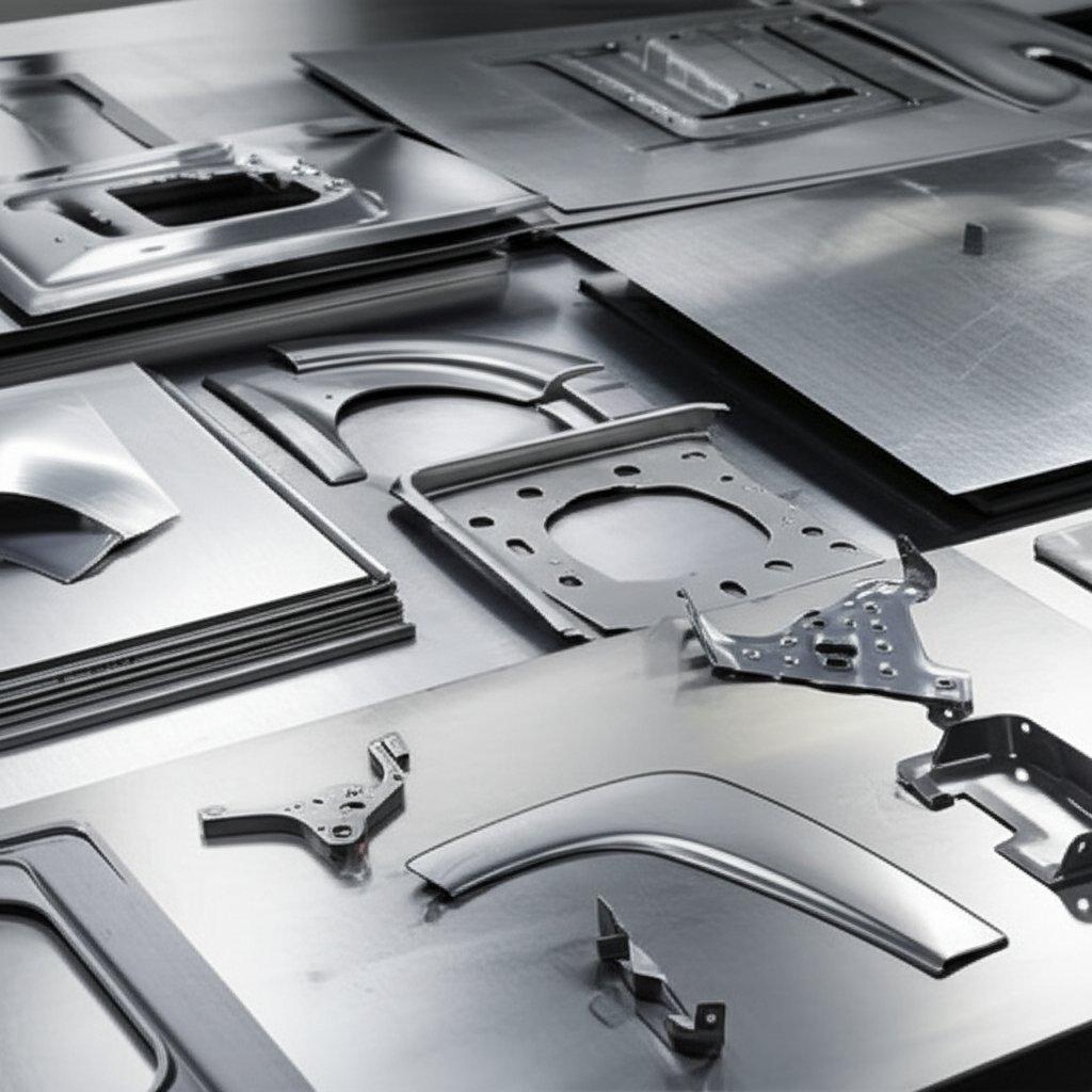
இந்த வரிசை ஒவ்வொரு காரிலும் நூற்றுக்கணக்கான பாகங்களாக மீண்டும் மீண்டும் செய்யப்படுகிறது. முத்திரை குத்துதல் என்பது தயாரிப்பதற்கான முதன்மை முறையாகும் பாடி-இன்-வைட் (BIW) பலகைகள்கடலின் கட்டமைப்பு எலும்புக்கூடுஅத்துடன் பிளேட்கள், வலுவூட்டல்கள் மற்றும் பல.
- கார்பஸ் பேனல்கள் (ஹாட்ஜ்கள், கதவுகள், கூரைகள், ஃபெண்டர்கள்)
- வலுவூட்டல்கள் (திரும்பல் கதிர்கள், குறுக்கு உறுப்புகள்)
- இருக்கை சட்டங்கள்
- பேட்டரி பெட்டிகள் மற்றும் தட்டுகள் (குறிப்பாக EV களில்)
- பொருத்துதல் அடைப்புக்குறிகள், ஆதரவுகள் மற்றும் பிற கட்டமைப்பு பாகங்கள்
ஏன் முத்திரை குத்துதல் செலவு, தரம் மற்றும் வேகம் ஆகியவற்றை அதிகரிக்கிறது
ஏன் உலோக முத்திரை தயாரிப்புத் தொழில் வாகன தொழில்நுட்பம் முன்னேறும்போது கூட, இந்த வாகனங்கள் இன்றியமையாததாக இருக்க முடியுமா? பதில் எளிது: முத்திரையிடல் இணையற்ற வேகம், துல்லியம் மற்றும் அளவிடக்கூடிய தன்மையை வழங்குகிறது. நவீன முத்திரை குத்தும் ஆலைகள் ஒரு மாறுபாட்டில் ஆயிரக்கணக்கான ஒரே மாதிரியான பாகங்களை உற்பத்தி செய்ய முடியும், உதிரிபாகங்களை குறைக்கிறது மற்றும் ஒவ்வொரு கூறுகளும் கடுமையான பாதுகாப்பு மற்றும் தரத் தரங்களை பூர்த்தி செய்கின்றன என்பதை உறுதிப்படுத்துகிறது. இந்த செயல்திறன் ஆட்டோமொபைல் தயாரிப்பாளர்கள் செலவுகளை போட்டித்தன்மையுடன் வைத்திருக்க அனுமதிக்கிறது, அதே நேரத்தில் இலகுவான, பாதுகாப்பான மற்றும் எரிபொருள் திறன் அதிகமான வாகனங்களை வழங்குகிறது.
மின்மயமாக்கல் மற்றும் இலகுரக போக்குகள் மேம்பட்ட உயர் வலிமை எஃகு மற்றும் அலுமினிய முத்திரைகளுக்கு தேவைகளைத் தூண்டுகின்றன. இந்த பொருட்கள் வடிவமைக்க கடினமாக உள்ளன, ஆனால் ஸ்டாம்பிங் தொழில்நுட்பம் சவாலை எதிர்கொள்ள பரிணமித்துள்ளது, இது வலுவான மற்றும் இலகுவான EV களை உருவாக்க அனுமதிக்கிறது.
உனக்கு தெரியுமா? வெள்ளை நிறத்தில் உள்ள கார்பஸ் (BIW) அமைப்பு மட்டும் ஒரு வாகனத்தின் மொத்த உற்பத்தி செலவில் 40% வரை கணக்கிட முடியும், இது திறமையான முத்திரையை லாபகரத்தன்மை மற்றும் தரத்தின் முக்கிய இயக்கி ஆக்குகிறது.
என உலோக முத்திரை தயாரிப்புத் தொழில் தொடர்ந்து புதுமைகளைத் தொடர்கிறது, வாகன உற்பத்தியாளர்களும் துல்லியம், அளவிடக்கூடிய தன்மை மற்றும் நம்பகத்தன்மையை வழங்கக்கூடிய கூட்டாளர்களைத் தேடுகிறார்கள். முத்திரையிடப்பட்ட பாகங்களை வாங்கும் போது, நவீன வாகனத் திட்டங்களின் தொழில்நுட்ப மற்றும் தளவாடத் தேவைகளை புரிந்து கொள்ளும் சப்ளையர்களைத் தேர்ந்தெடுப்பது மிகவும் முக்கியம். நம்பகமான ஆதாரத்தை தேடுவோருக்கு, தாள் அச்சிடும் தொழில் ஷாயோய் மெட்டல் பாகங்கள் சப்ளையர் வழங்கும் தீர்வுகள் பொருட்கள், செயல்முறைகள் மற்றும் அளவுகள் ஆகியவற்றில் ஒருங்கிணைந்த திறன்களை வழங்குகின்றன.
சுருக்கமாக, முத்திரை குத்துதல் என்பது செயல்முறையின் ஒரு படி மட்டுமல்ல, அது நவீன கார் தயாரிப்பின் அடித்தளமாகும். முதல் வடிவமைப்பு வரைபடத்திலிருந்து இறுதிச் சடங்கு வரை, சாலையில் செல்லும் ஒவ்வொரு வாகனமும் பாதுகாப்பு, பாணி மற்றும் செயல்திறனை அளவிலானதாக வழங்க துல்லியம் மற்றும் முத்திரை குத்தலின் சக்தியை நம்பியுள்ளது.
அழுத்தங்கள் அளவுருக்கள் மற்றும் வடிவமைத்தல் ஓட்டம்
ஆட்டோமொபைல் ஸ்டாம்பிங் தொழிற்சாலையில் நடந்து செல்லும்போது, அச்சுப்பொறிகளின் இடி முழக்கம் கவனிக்காமல் போவது கடினம். ஆனால் ஒருவரை வண்டி செய்திகள் அழுத்து அமைப்பு ஒரு நுட்பமான ஹூட் பேனலுக்கு சரியான தேர்வு, அதே நேரத்தில் மற்றொரு வலுவான சட்டம் ஆதரவு சரியானது? நவீன பத்திரிகைகளை இயக்கும் பத்திரிகை வகைகள், அளவுகள் மற்றும் கட்டுப்பாட்டு அம்சங்களை நாம் உடைப்போம் ஸ்டாம்பிங் உற்பத்தி செயல்முறை .
குழு மற்றும் கட்டமைப்பு பாகங்களுக்கான பத்திரிகை தேர்வு
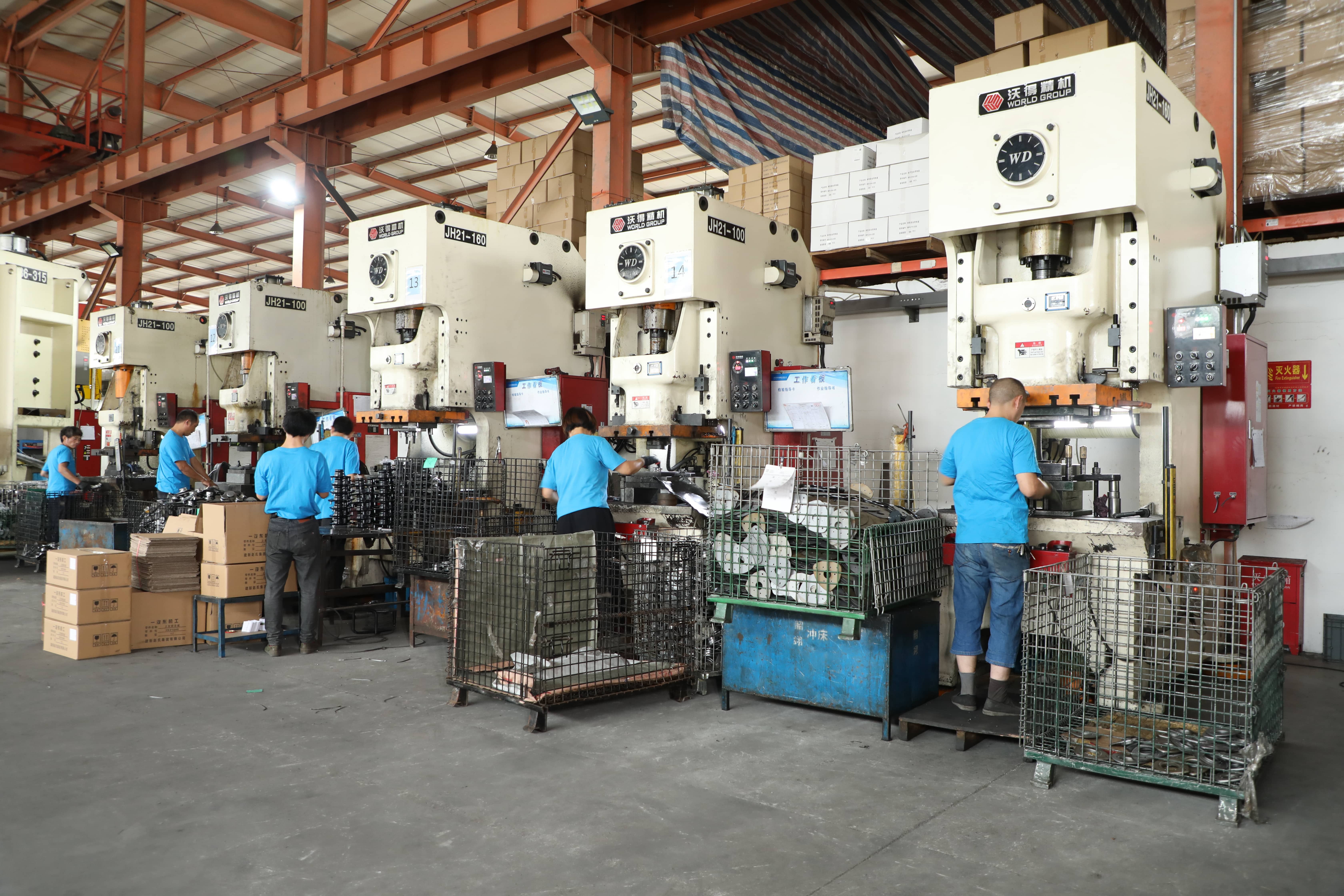
சிக்கலான ஒலி? அது இருக்கலாம், ஆனால் பத்திரிகை வகைகளை புரிந்துகொள்வது முதல் படியாகும். வாகன உலோக முத்திரையில் பயன்படுத்தப்படும் மூன்று முதன்மை பத்திரிகை வகைகள்ஃ
| பத்திரிகை வகை | வழக்கமான டொனாஜ் வரம்பு | வேகம் (SPM) | சிறந்த பயன்பாடுகள் |
|---|---|---|---|
| Mekanikku | 802,500 டன் | 20–60+ | அதிக அளவு வெளிப்புற அறைகள், ஆழமற்ற முத்திரைகள் |
| ஹைட்ராலிக் | 1004,000+ டன் | 5–30 | ஆழமான இழுப்புக் கோப்பைகள், சிக்கலான வடிவங்கள், தடிமனான பொருட்கள் |
| செர்வோ | 2002,500 டன் | மாறி (பட்டியிடக்கூடியது) | துல்லியமான பாகங்கள், AHSS, தனிப்பயனாக்கப்பட்ட இயக்கம் விவரக்குறிப்புகள் |
இயந்திர அச்சுகள் வேகமான, மீண்டும் மீண்டும் செய்வதற்கான முதுகெலும்பாக இருக்கின்றன அழுத்துதல் மற்றும் முத்திரையிடுதல் ஹைட்ராலிக் பிரஸ்கள் ஆழமான இழுப்பில் பிரகாசித்து, தடிமனான அல்லது அதிக வலிமை கொண்ட பொருட்கள் உருவாகின்றன. மென்பொருள் தயாரிப்பு இயந்திரங்கள், கணினிக்கு ஏற்றவாறு இயங்கக்கூடிய நெகிழ்வுத்தன்மையைக் கொண்டுள்ளன.
டோன், ஸ்ட்ரோக் ரேட், மற்றும் எரிசக்தி கணக்கீடுகள்
சரியான பிரஸ் தேர்ந்தெடுப்பது அதிகபட்ச வலிமை பற்றி மட்டுமல்ல. நீங்கள் தேவையான டோன்ஜை கணக்கிட்டு, பிரஸ் முழு ஸ்ட்ரோக்கிலும் போதுமான ஆற்றலை வழங்குவதை உறுதி செய்ய வேண்டும். இங்கே ஒரு நடைமுறை உதாரணம் அடித்துரை செயல்பாடு :
- சுற்றளவு (P) கண்டறியவும்ஃ உங்களுக்கு ஒரு செவ்வக பகுதி உள்ளது என்று வைத்துக்கொள்வோம், 400 மிமீ x 200 மிமீ. சுற்றளவு = 2 × (400 + 200) = 1,200 மிமீ = 1.2 மீ.
- பொருள் தடிமன் (t): 1.2 மிமீ = 0.0012 மீ.
- இறுதி இழுவிசை வலிமை (UTS): மென்மையான எஃகுக்கு 350 MPa (350,000,000 N/m2) என்று வைத்துக்கொள்வோம்.
- வெட்டு வலிமை (S): பொதுவாக 60% யுடிஎஸ்ஃ 0.6 × 350 = 210 எம்பிஏ (210,000,000 என்/எம்2).
-
டொன் அளவுஃ டொன் = P × t × S
- 1.2 m × 0.0012 m × 210,000,000 N/m2 = 302,400 N ≈ 30.8 டன் (டன்ஸில் 9,807 ஆக வகுக்கப்படுகிறது)
- பாதுகாப்பு காரணி பயன்படுத்தவும்ஃ பாதுகாப்பு வரம்பை 1.2 ஆல் பெருக்கவும்ஃ 30.8 × 1.2 = 36.96 டன்.
எனவே, இந்த பகுதிக்கு குறைந்தபட்ச திறன் 37 டன் கொண்ட ஒரு பத்திரிகையை நீங்கள் குறிப்பிடுவீர்கள். ஆனால், அதை மட்டும் நிறுத்தாதீர்கள். எப்போதும் பத்திரிகையின் ஆற்றல் வளைவை சரிபார்க்கவும். அதிவேக வேலைகளில், ஆற்றல் உச்ச சுமை மட்டுமல்லகுறிப்பாக மேம்பட்ட எஃகுகளில் வரையறுக்கும் காரணிகளாக இருக்கலாம் (மூலம்) .
நினைவில் கொள்ளுங்கள்ஃ உச்ச டோன்ஜேஜ் மட்டுமல்லாமல், பிரஸ் ஆற்றலும், அதிவேக முத்திரை தயாரிப்பு செயல்முறை செயல்திறனை அடிக்கடி கட்டுப்படுத்துகிறது, குறிப்பாக தடிமனான அல்லது அதிக வலிமை கொண்ட பொருட்களுடன்.
செயல்திறன் பற்றி என்ன? ஒரு பகுதியின் சுழற்சி நேரம் ஸ்ட்ரோக் வீதம் (SPM), டை சிக்கலான தன்மை மற்றும் பரிமாற்ற ஆட்டோமேஷன் ஆகியவற்றைப் பொறுத்தது. உதாரணமாக, ஒரு மெக்கானிக்கல் பிரஸ் 40 SPM வேகத்தில் இயங்கும் போது, ஒரு முறை வெளியில் இறங்கும் ஒரு துண்டு 2,400 ஸ்டாம்பிங் பாகங்கள் ஒரு மணி நேரத்திற்கு, மென்மையான பொருள் நுழைவு மற்றும் வெளியேற்றத்தை கருத்தில் கொண்டு.
வெற்றுக் கைப்பிடி மற்றும் தலையணை கட்டுப்பாட்டு அடிப்படைகள்
உருவான பகுதிகளில் சுருக்கங்கள் அல்லது பிளவுகள் இருப்பதை நீங்கள் கவனித்திருக்கிறீர்களா? இங்குதான் வெற்று தக்கவைப்பு சக்தி மற்றும் மெத்தை அமைத்தல் ஆகியவை வருகின்றன. வெற்று வைத்திருப்பவர் (அல்லது வைத்திருத்தல்) தாளில் கட்டுப்படுத்தப்பட்ட அழுத்தத்தை பயன்படுத்துகிறார், வடிவமைப்பின் போது குறைபாடுகளைத் தடுக்கிறார். ஆழமான இழுவை மற்றும் AHSS க்கு அவசியமான திட்டமிடக்கூடிய சக்தி சுயவிவரங்களை ஆதாரத்தின் கீழ் உள்ள ஹைட்ராலிக் தலையணைகள் அனுமதிக்கின்றன. தட்டுகளில் வேலை செய்யப்படும் அல்லது செருகப்பட்ட கற்களை வரைதல், மேலும் பொருள் ஓட்டத்தை கட்டுப்படுத்துதல்.
- வழக்கமான தலையணை சக்திகள்ஃ 1030% மென்மையான எஃகு உருவாகும் வலிமை; AHSS மற்றும் அலுமினியத்திற்கு அதிகமானது.
- கணிதக் காளான் அமைத்தல்: உலோக ஓட்டத்தை நன்றாக ஒழுங்கமைக்க மற்றும் கிழிப்பு அல்லது சுருக்கத்தைத் தடுக்க மணி வடிவமைப்பை அல்லது இருப்பிடத்தை சரிசெய்யவும்.
- தானியங்கி முத்திரை குத்துதல்ஃ நவீன அச்சுப்பொறிகள் ஒவ்வொரு பகுதியிலும் வலிமை வளைவுகள் மற்றும் மெத்தை நடவடிக்கைகளை நிரல்படுத்தலாம், இது நிலைத்தன்மையை அதிகரிக்கிறது மற்றும் சிதைவைக் குறைக்கிறது.
பத்திரிகை அளவுருக்களை சரியாக பெறுவது குறைவான குறைபாடுகளையும் அதிக உற்பத்தித்திறனையும் குறிக்கிறது. அடுத்து, உங்கள் முத்திரை வேலைத்திட்டத்தின் தரம் மற்றும் செயல்திறனை எவ்வாறு வடிவமைப்பது என்பதைப் பார்ப்போம்.
ஆட்டோமொபைல் ஸ்டாம்பிங் துல்லியத்தின் இதயம்
சில முத்திரை வேலைகள் ஏன் மாதக்கணக்கில் சிக்கல் இல்லாமல் இயங்குகின்றன, மற்றவர்கள் ஏன் தொடர்ந்து கருவி உடைப்பு மற்றும் பகுதி குறைபாடுகளுடன் போராடுகிறார்கள் என்று எப்போதாவது யோசித்திருக்கிறீர்களா? இதற்கு பதில் பெரும்பாலும் டை பொறியியல் மற்றும் பராமரிப்பு பற்றிய விவரங்களில் உள்ளது. நாம் அத்தியாவசியங்களை உடைத்து பார்ப்போம், எனவே நீங்கள் ஒவ்வொரு பகுதியிலும் சரியான தேர்வுகளை செய்யலாம், கார் எட்ரிங் மாறிகள் வரை முனைமச் செதுக்குதல் .
இறகு வகைகள் மற்றும் ஒவ்வொன்றையும் எப்போது தேர்வு செய்வது
சிக்கலான ஒலி? அது இருக்கலாம், ஆனால் முக்கிய டயர் வகைகளை புரிந்துகொள்வது தேர்வு செய்வதை மிகவும் எளிதாக்குகிறது. சரியான டீ வகை பகுதி வடிவியல், உற்பத்தி அளவு மற்றும் சகிப்புத்தன்மை தேவைகள் சார்ந்துள்ளதுஃ
| டை வகை | பார்வைகள் | தவறுகள் | பொதுவான கேப்எக்ஸ் | வேகம் | சிறப்பாக பொருந்தும் |
|---|---|---|---|---|---|
| தொடர்ச்சியான | அதிக வேகம், குறைந்த உழைப்பு, சிக்கலான பகுதிகளுக்கு நல்லது | அதிக ஆரம்ப செலவு, சிக்கலான அமைவு | உயர் | வேகமாக (அதிகபட்சம் 60+ SPM) | பிளேட்கள், சிறிய வலுவூட்டல்கள், தொடர் செம்பட்டை அச்சிடும் உத்வேக பாகங்கள் |
| (){ மாற்றம் | பெரிய/கடினமான பாகங்களை கையாளுகிறது, நெகிழ்வானது | முற்போக்கானதை விட மெதுவாக, அதிக தரை இடம் | உயர் | சரி | வெளிப்புறப் பலகைகள், கட்டமைப்புப் பாகங்கள் |
| சேர்மங்கள் | ஒரு ஸ்ட்ரோக்கிற்கு பல வெட்டுக்கள்/வடிவங்கள், நடுத்தர அளவிற்கு செலவு குறைந்தவை | வரையறுக்கப்பட்ட சிக்கலானது, குறைந்த நெகிழ்வுத்தன்மை | சராசரி | சரி | துடைப்பாளர்கள், எளிய வளையங்கள் |
| ஒரு-நிலை | குறைந்த செலவு, எளிதில் மாற்றம் | மெதுவான, அதிக உழைப்பு, அதிக அளவுக்கு அல்ல | குறைவு | மெதுவாக | முனைமச் செதுக்குதல் , குறைந்த அளவு பாகங்கள் |
| டேண்டம் | பெரிய பாகங்கள் நல்ல, படிப்படியாக உருவாக்கும் அனுமதிக்கிறது | அதிக உழைப்பு, பல அச்சுகளும் தேவை | உயர் | மெதுவாக அல்லது மிதமாக | ஹூட்ஸ், கதவுகள், சிக்கலான BIW பேனல்கள் |
பெரிய அளவிலான, சிக்கலான பாகங்களுக்கு, oem முற்போக்கான முத்திரை இறக்கிறது செல்ல வேண்டும். பெரிய பேனல்களுக்கு மாற்று அச்சுகள் பிரகாசிக்கின்றன, அதே நேரத்தில் ஒற்றை நிலைய அச்சுகள் ஆராய்ச்சி மற்றும் மேம்பாடு மற்றும் முன்மாதிரி தயாரிப்புக்கு ஏற்றவை.
டை பொருட்கள், வெப்ப சிகிச்சை, பூச்சுகள்
தவறான மடிப்புப் பொருளுடன் உயர் வலிமை கொண்ட எஃகு உருவாகிறது என்று கற்பனை செய்து பாருங்கள், உடைதல், சிப்பிங் மற்றும் வேலையில்லா நேரம் கிட்டத்தட்ட உத்தரவாதம் அளிக்கப்படுகிறது. நீங்கள் தெரிந்து கொள்ள வேண்டியதுஃ
- கருவி எஃகுஃ D2 மற்றும் DC53 ஆகியவை பிரபலமானவை நடுவர் செயற்பாட்டுக்கலன் பயன்பாடுகள், கடினத்தன்மை மற்றும் கடினத்தன்மை ஆகியவற்றின் சமநிலையை வழங்குகிறது. கடினமான வேலைகளுக்கு, தூள் உலோகவியல் (PM) எஃகுகள் சிறந்த உடை மற்றும் சிதைவு எதிர்ப்பை வழங்குகின்றன (மூலம்) .
- கார்பைடு இடுகைகள்: உயர் உடைப்பு பகுதிகளில் பயன்படுத்தப்படுகிறது, குறிப்பாக AHSS மற்றும் அலுமினியத்துடன் ஆயுளை நீட்டிக்க.
- வெப்ப சிகிச்சைஃ சரியான தணிப்பு கடினத்தன்மைக்கு மட்டுமல்லாமல் தாக்க சகிப்புத்தன்மையிலும் முக்கியமானது. இந்த படிநிலையை தவிர்ப்பது அல்லது அவசரப்படுவது ஆரம்பகால தோல்விக்கு வழிவகுக்கும்.
- பூச்சுகள்ஃ டைட்டானியம் நைட்ரைடு (TiN), டைட்டானியம் அலுமினிய நைட்ரைடு (TiAlN), மற்றும் குரோமியம் நைட்ரைடு (CrN) பூச்சுகள் எரிச்சலையும் உராய்வுகளையும் குறைக்கின்றன. பிவிடி பூச்சுகள் AHSS க்கு முன்னுரிமை அளிக்கப்படுகின்றன, ஏனெனில் அடி மூலக்கூறு மென்மையாக்கப்படுவதற்கான ஆபத்து குறைவாக உள்ளது.
அடிப்படை பொருள், வெப்ப சிகிச்சை மற்றும் பூச்சு ஆகியவற்றின் சரியான கலவையைத் தேர்ந்தெடுப்பது, மரபணு எஃகுகளுடன் ஒப்பிடும்போது, சில நேரங்களில் 10 மடங்கு அல்லது அதற்கு மேற்பட்டதாக இருக்கும்.
அனுமதி சூத்திரங்கள், ஆயுள், பராமரிப்பு
நீங்கள் நினைப்பதை விட, துடிப்புக்கும் துடிப்புக்கும் இடையிலான இடைவெளி முக்கியமானது. மிகவும் இறுக்கமாக, மற்றும் நீங்கள் கோபத்தை மற்றும் சிதைவு பார்ப்பீர்கள். மிகவும் தளர்வான, மற்றும் புர்ஸ் மற்றும் மோசமான விளிம்பு தரம் தோன்றும், குறிப்பாக AHSS உடன்ஃ
தடிமன் மற்றும் விளிம்பு தரத்தை கட்டுப்படுத்த, மேம்பட்ட உயர் வலிமை எஃகுகளுக்கு, தடிமன் விகிதத்தில் டை கிளியரன்ஸை அமைக்கவும்.
பசுமைப் பூச்சிகள் உங்கள் கருவிகளை சிறந்த நிலையில் வைத்திருக்க ஒரு எளிய சரிபார்ப்பு பட்டியல் இங்கேஃ
- தினசரி: காட்சி ஆய்வு, சுத்தம் டீ மேற்பரப்புகள், குப்பைகள் சோதனை.
- ஒரு வாரத்திற்கு ஒரு முறை: நகரும் பாகங்களை மசகு செய்யுங்கள், சீரமைப்பு மற்றும் பிணைப்புகளை சரிபார்க்கவும், உடை அல்லது சிப்பிங் ஆகியவற்றை ஆய்வு செய்யவும்.
- PPAP அல்லது Major Serviceக்குஃ முழுமையான அகற்றல், வேலை மேற்பரப்புகளை மெருகூட்டுதல், அளவீடு மற்றும் மீட்டமைத்தல், உடைந்து போன செருகுநிரல்களை மாற்றுதல், அனைத்து கண்டுபிடிப்புகளையும் ஆவணப்படுத்துதல்.
கவனிக்க வேண்டிய பொதுவான செயலிழப்பு முறைகள் பின்வருமாறுஃ
- உடைஃ உராய்வு காரணமாக படிப்படியாக பொருள் இழப்பு பொருள் பூச்சுகள் மற்றும் சரியான மசகு மூலம் குறைக்க.
- சிப்பிங்: சிறிய துண்டுகள் அடிக்கடி கூர்மையான மூலைகளில் உடைந்து போகின்றன, மேலும் கடினமான கருவி எஃகு மற்றும் சரியான ரேடியஸ் பயன்படுத்தி மேம்படுத்தப்படுகின்றன.
- கால்ஃ மென்மையான பூச்சுகள் மற்றும் மேம்பட்ட பூச்சுகள் மூலம் டை மற்றும் தாள் இடையே பொருள் பரிமாற்றத்தை தடுக்கிறது.
- வெப்ப பரிசோதனைஃ வெப்ப சுழற்சியின் காரணமாக மேற்பரப்பு விரிசல்கள் குறைக்கப்படுகின்றன.
உகந்த வடிவமைப்பு மற்றும் முன்முயற்சி பராமரிப்பு என்பது செயல்பாட்டு நேரத்தை பற்றி மட்டுமல்ல, அவை ஒவ்வொரு முத்திரை செயல்பாட்டிலும் நிலையான தரம் மற்றும் செலவு கட்டுப்பாட்டின் முதுகெலும்பாகும். அடுத்து, சரியான பொருள் தேர்வு மற்றும் வடிவமைப்பு-உற்பத்தி விதிகளை உங்கள் முடிவுகளை மேலும் அதிகரிக்க முடியும் எப்படி ஆராயலாம்.
முத்திரை குத்தலுக்கான பொருட்கள் அணி மற்றும் வடிவமைப்பு விதிகள்
கார் உலோக முத்திரைகளுக்கான ஒரு பகுதியை வடிவமைக்கும் பணியை நீங்கள் செய்யும்போது, கேள்விகள் பறக்கத் தொடங்குகின்றன. மென்மையான எஃகு சுத்தமாக வளைந்து விடும்? அலுமினியத்தால் சிக்கலான இழுவை சமாளிக்க முடியுமா? எப்படி நீங்கள் உங்கள் சகிப்புத்தன்மையை அழித்து இருந்து ஸ்பிரிங்பேக் தடுக்க? மிகவும் பொதுவான பொருட்கள், அவற்றின் நன்மை தீமைகள் மற்றும் வடிவமைப்பு-உற்பத்தி (DFM) விதிகள் ஆகியவற்றை நாம் உடைத்து விடுவோம்.
ஆட்டோமொபைல் ஸ்டாம்பிங்ஸ் க்கான பொருட்கள் மேட்ரிக்ஸ்
சரியான பொருளைத் தேர்ந்தெடுப்பது என்பது மிகவும் மலிவானதைத் தேர்ந்தெடுப்பதை விட அதிகம். ஒவ்வொரு விருப்பமும் - பாரம்பரிய எஃகு தகடு முத்திரை, மேம்பட்ட உயர் வலிமை எஃகு அல்லது அலுமினிய அலாய் ஆகியவற்றுடன் - அதன் சொந்த சமநிலை, வலிமை மற்றும் மறுபயன்பாட்டு அபாயத்தை கொண்டுள்ளது. கார் உலோக பாகங்கள் தேர்ந்தெடுப்பதில் உங்களுக்கு வழிகாட்டக்கூடிய ஒரு நடைமுறை ஒப்பீடு இங்கேஃ
| கோட்டு | வழக்கமான தடிமன் (மிமீ) | பொதுவான பாகங்கள் | பார்வைகள் | தவறுகள் | DFM குறிப்புகள் |
|---|---|---|---|---|---|
| மென்மையான எஃகு (CR4, IF) | 0.6–2.2 | கார்பஸ் பேனல்கள், மூடுதல்கள் | எளிதில் உருவாகும், குறைந்த செலவு | குறைந்த வலிமை, கனமான | சிறிய வளைவு ரேடியஸ், குறைந்த ஸ்பிரிங்பேக் |
| HSLA (உயர் வலிமை குறைந்த அலாய்) | 0.8–2.5 | வலுவூட்டல்கள், பிணைப்புகள் | நல்ல வலிமை-எடை, மின்கலம் | மிதமான ஸ்பிரிங்பேக் | குறைந்தபட்ச வளைவு ரேடியஸ் ≥ 2T; ஸ்பிரிங்பேக்கை அனுமதிக்கவும் |
| DP590/780/980 (இரட்டை கட்டம்) | 0.8–2.0 | மோதல் கதிர்கள், பி-ஸ்தானங்கள் | அதிக வலிமை, நல்ல ஆற்றல் உறிஞ்சுதல் | உயரமான ஸ்பிரிங்பேக், உருவாக்குவது கடினமானது | குறைந்தபட்ச வளைவு ரேடியஸ் ≥ 3T; இறுக்கமான டை லிப்பரேன்ஸ் |
| 22MnB5 (அடிப்படை கடினப்படுத்தப்பட்ட எஃகு) | 1.0–2.0 | தூண்கள், கதவு கம்பிகள் | உருவகப்படுத்திய பின் மிக உயர்ந்த வலிமை | சூடான வடிவமைத்தல் தேவை, சிக்கலான செயல்முறை | வெப்ப சிகிச்சைக்கான வடிவமைப்பு; கூடுதல் வடிவமைக்கும் நிலைகளுக்கான திட்டம் |
| அலுமினியம் 5xxx/6xxx (எ. கா. 6016-T4) | 0.8–2.0 | ஹூட்ஸ், டேப்ஸ், பேட்டரி பெட்டிகள் | இலகுரக, அரிப்பை எதிர்க்கும் | உயர்ந்த ஸ்பிரிங்பேக், மேற்பரப்பு உணர்திறன் | குறைந்தபட்ச வளைவு ரேடியஸ் ≥ 2T; இறுக்கமான மூலைகளை தவிர்க்கவும் |
இந்த பொருள் தேர்வுகள் வாகன கூறுகளுக்கான உலோக முத்திரைகளின் தற்போதைய பரிணாமத்தை பிரதிபலிக்கிறது, ஏனெனில் OEM கள் எடை குறைப்பு, பாதுகாப்பு மற்றும் செலவு ஆகியவற்றை சமநிலைப்படுத்த முயல்கின்றன (மூலம்) .
முத்திரை குத்தலுக்கான வடிவமைப்பு விதிமுறைகள்
செலவு மிகுந்த மறு வேலை, கருவி உடைப்பு அல்லது சிதைவை தவிர்க்க விரும்புகிறீர்களா? வாகன உலோக அழுத்தங்கள் மற்றும் தகடு முத்திரை பாகங்கள் வடிவமைக்கும் போது இந்த DFM விதிகளை பின்பற்றவும்ஃ
-
குறைந்தபட்ச வளைவு ரேடியோஃ
- மென்மையான எஃகுஃ ≥ 1T (T = தடிமன்)
- HSLA: ≥ 2T
- DP/AHSS: ≥ 3T
- அலுமினியம்ஃ ≥ 2T
- துளை விட்டம்ஃ உயர் வலிமை எஃகுகளுக்கு ≥ 2T, நெகிழ்வான பொருட்களுக்கு ≥ 1.2T
- துளை முதல் விளிம்பு வரை உள்ள தூரம்ஃ ≥ 2T
- குறைந்தபட்ச அகலம்ஃ ≥ 3T
- இழுவை விகிதம்: ஆழமாக இழுக்கப்பட்ட பகுதிகளுக்கு 2.0 க்கும் குறைவாக வைத்திருங்கள்
- வசந்தகால கொடுப்பனவுஃ AHSS க்கு 310°, அலுமினியத்திற்கு 24° சேர்க்கவும்
இந்த விதிகளைப் பின்பற்றுவது உங்கள் உலோக முத்திரை மோட்டார் வடிவமைப்புகளை வலுவான மற்றும் மீண்டும் மீண்டும் செய்யக்கூடியது என்பதை உறுதிப்படுத்த உதவுகிறது, பொருள் தரங்கள் உருவாகும்போது கூட.
ஸ்பிரிங்பேக் மற்றும் இழப்பீட்டு உத்திகள்
ஸ்பிரிங்பேக் என்பது இறுக்கமான சகிப்புத்தன்மைகளின் எதிரி, குறிப்பாக நீங்கள் அதிக வலிமை கொண்ட எஃகு அல்லது இலகுரக அலுமினியத்திற்கு மாறும்போது. எனவே, எப்படி நீங்கள் உங்கள் முத்திரைகள் ஸ்பெக் வைத்து?
- அதிகபட்சமாக வளைக்க அல்லது அதிகபட்சமாக வடிவமைக்கஃ கூடுதல் கோணத்துடன் வடிவமைக்கப்பட்ட பாகங்கள், வடிவமைக்கப்பட்ட பிறகு அவை சரியான வடிவத்திற்கு தளர்த்தப்படுகின்றன.
- நீட்டிக்கப்பட்ட பின் செயல்பாடுகள்ஃ கோண மாற்றம் மற்றும் பக்கவாட்டு சுருட்டைக் குறைக்க டை-ஸ்ட்ரெச்சிங் (ஸ்டேக் பீட்ஸ் அல்லது கலப்பின பீட்ஸ் பயன்படுத்தி) பயன்படுத்தவும்.
- டை மற்றும் செயல்முறை அமைத்தல்ஃ இறுக்கமான டை கிளியரன்ஸ் (10AHSS க்கான தடிமன் 20%), கூர்மையான ரேடியஸ் மற்றும் நெகிழ்வான மீட்பு குறைக்க உகந்த மணி வடிவியல் பயன்படுத்தவும்.
- வடிவியல் கூடுதல் அம்சங்கள்ஃ வளைவுகளைத் தடுக்கவும், மீதமுள்ள அழுத்தங்களைக் குறைக்கவும், மணிகள், அம்புகள் அல்லது கடினப்படுத்துபவைகளைச் சேர்க்கவும்.
2025ல் வென்ற சூத்திரம் எடை குறைப்பு, வடிவமைக்கக்கூடிய தன்மை மற்றும் செலவு ஆகியவற்றை சமநிலைப்படுத்துவதாகும். எனவே உங்கள் பொருள் மற்றும் வடிவமைப்பு தேர்வுகள் ஒவ்வொரு பகுதியின் செயல்திறன் மற்றும் உற்பத்தித் தேவைகளுக்கு எப்போதும் பொருந்தும்.
இந்த பொருட்கள் மற்றும் DFM நுண்ணறிவுகளைப் பயன்படுத்துவதன் மூலம், நீங்கள் வாகன உலோக முத்திரைகளின் முழு மதிப்பையும் திறந்துவிடுவீர்கள், ஒவ்வொரு புதிய வாகன தளத்திற்கும் இலகுவான, வலுவான மற்றும் துல்லியமான வாகன உலோக பாகங்களை வழங்குவீர்கள். அடுத்து, மிகவும் பொதுவான முத்திரை குறைபாடுகளை மற்றும் உங்கள் கீழ் வரிகளை பாதிக்கும் முன் அவற்றை எவ்வாறு சரிசெய்வது என்பதைப் பற்றி பார்ப்போம்.
குறைபாடுகளை சரிசெய்தல் மற்றும் சரிசெய்தல் நடவடிக்கைகள்
ஒரு முத்திரையிடப்பட்ட ஹூட்டில் ஒரு சுருக்கத்தை அல்லது ஒரு பிளேக்கில் ஒரு புருவத்தை நீங்கள் எப்போதாவது கவனித்திருக்கிறீர்களா, மற்றும் ஆச்சரியப்பட்டீர்கள், எப்படி முத்திரை குத்துவது பெரும்பாலான நேரங்களில் நன்றாக வேலை செய்கிறது, ஆனால் சில நேரங்களில் தவறாக செல்கிறது? இதற்கு பதில், பொதுவான குறைபாடுகளை புரிந்து கொள்வதில் உள்ளது. ஸ்டாம்பிங் செயல்முறை மற்றும் அவற்றை எப்படி அடையாளம் கண்டு, சரி செய்து, அவற்றை உங்கள் நேரத்தையும் பணத்தையும் இழக்காமல் தடுப்பது என்று தெரிந்து கொள்வது. மிகவும் அடிக்கடி ஏற்படும் முத்திரை பிரச்சினைகள், அவற்றின் மூல காரணங்கள் மற்றும் உங்கள் முத்திரையை பாதுகாக்க நீங்கள் எடுக்கக்கூடிய நடைமுறை நடவடிக்கைகளை நாம் உடைப்போம். உற்பத்தி ஸ்டாம்பிங் வரிகள் சீராக இயங்கும்.
பொதுவான முத்திரை குறைபாடுகள் மற்றும் மூல காரணங்கள்
சிக்கலான ஒலி? நீங்கள் என்ன தேட வேண்டும் என்று தெரியும் போது இல்லை. உற்பத்தி குறைபாடுகளில் மிகவும் பொதுவான முத்திரை குத்தல் செயல்முறை மற்றும் அவை ஏன் நிகழ்கின்றன என்பது இங்கேஃ
| குறைபாடு | சாத்தியமான காரணங்கள் | ஆய்வு நடவடிக்கைகள் | திருத்த நடவடிக்கைகள் | தடுப்பு கட்டுப்பாடுகள் |
|---|---|---|---|---|
| சுருக்கங்கள் | குறைந்த வெற்று-தொகுப்பு வலிமை (BHF), தவறான கரடி கட்டுப்பாடு, அதிகப்படியான பொருள், சீரற்ற திரிபு | காட்சி ஆய்வு, உணர்வாளர் அளவீடு, CMM சுயவிவர ஸ்கேன் | BHF அதிகரிக்க, சேர்க்க / சரி வரைதல் மணிகள், வெற்று வடிவம் உகந்ததாக்க | BHF சுயவிவரங்களை அமைத்தல், உருவகப்படுத்துதல், வழக்கமான கரடி சோதனைகள் |
| கிழித்தல்/நெக்கிங் | அதிக அழுத்தம், மோசமான பொருள் நெகிழ்வுத்தன்மை, இறுக்கமான ரேடியோக்கள், அதிகப்படியான மெல்லியமைத்தல், கருவி உடைத்தல் | காட்சி, வெட்டு மற்றும் செதுக்குதல், தடிமன் வரைபடம், ஒளியியல் ஸ்கேன் | ரேடியஸ் அதிகரிக்க, மேம்படுத்தல் பொருள், போலிஷ் கருவிகள், மாற்றம் க்ளீப் | பொருள் சான்றிதழ் சோதனைகள், டை பராமரிப்பு, உருவகப்படுத்துதல் |
| திரும்பி வருதல் (springback) | உயர் வலிமை பொருள், போதுமான அளவு வளைவு, குறைந்த வடிவமைக்கும் சக்தி | 3D ஸ்கேன், CMM, CAD உடன் ஒப்பிடு, பொருத்துதல் சோதனை | அதிகபட்ச வளைவு, கொத்துகள்/நடிகளைச் சேர்ப்பது, பிந்தைய நீட்டிப்பு, செயல்முறை சரிசெய்தல் | ஸ்பிரிங்பேக்கிற்கான வடிவமைப்பு, செயல்முறை உருவகப்படுத்துதல், டை இன்-காமன்ஸ்மென்ஷன் |
| பர்ஸ்/பிளான்கிங் பர்ஸ் | உடைந்துபோன அல்லது மங்கலான கருவிகள், தவறான டை கிளியர்ஷிப், தவறான வெட்டு கோணம் | எட்ஜ் ஃபீலர், விஷுவல், மைக்ரோஸ்கோப், வெட்டு மற்றும் கெட்ச் | கருவிகளை கூர்மைப்படுத்துதல்/மாற்றுதல், டீ-கிளீன்ஷை மீட்டமைத்தல், பொலிஷ் விளிம்புகள் | கருவிகளின் ஆயுள் கண்காணிப்பு, வழக்கமான கூர்மைப்படுத்துதல், அனுமதி சோதனைகள் |
| மேற்பரப்பு நெரிசல்/இன்டென்டேஷன் | மோசமான மசகு, டீவில் உள்ள சிதைவுகள், கரடுமுரடான டீ மேற்பரப்பு, அதிக அழுத்த வேகம் | காட்சி, தொடுதல், மேற்பரப்பு ஸ்கேன் | மெருகூட்டல் மேம்படுத்த, சுத்தமான டீ, போலிஷ் மேற்பரப்புகள், வேகம் மேம்படுத்த | திட்டமிட்ட சுத்தம், மசகு கண்காணிப்பு, அச்சிடும் வேகத்திற்கான SOP கள் |
விரைவாகக் கண்டறிதல் மற்றும் கட்டுப்படுத்துதல்
ஒரு முக்கியமான பகுதியில் ஒரு பிளவு அல்லது புருவத்தை நீங்கள் கண்டறிந்திருப்பதை கற்பனை செய்து பாருங்கள். அடுத்து என்ன? விரைவான கண்டறிதல் மற்றும் கட்டுப்பாடு உங்கள் முதல் பாதுகாப்பு வரிகள். குறைபாடுகள் பெருகுவதற்கு முன்பே அவற்றை எப்படி கண்டறிவது என்பது இங்கேஃ
- கண்ணோட்டம்: விரைவான, மேற்பரப்பு மற்றும் விளிம்பு பிரச்சினைகளுக்கு பயனுள்ளதாக இருக்கும்.
- உணர்திறன் அளவீடுஃ புர்ஸ் மற்றும் விளிம்பு முறைகேடுகள் கண்டறிகிறது.
- ஒளியியல்/சிஎம்எம் ஸ்கேனிங்: உயர் துல்லியமான சோதனைகள் ஸ்பிரிங்பேக், சுருக்கம், மற்றும் தடிமன்.
- வெட்டு மற்றும் எட்ச்: மேற்பரப்பில் காணப்படாத உள் விரிசல்கள் அல்லது மெல்லியமைப்பை வெளிப்படுத்துகிறது.
உதவிக்குறிப்புஃ உங்கள் ஸ்டாம்பிங் செயல்முறையின் முக்கிய புள்ளிகளில் இந்த ஆய்வுகளை ஒருங்கிணைக்கவும்
திருத்த மற்றும் தடுப்பு நடவடிக்கைகள் (CAPA)
எனவே, நீங்கள் ஒரு குறைபாடு கண்டறிந்துள்ளோம். இப்போது என்ன? சிக்கலை சரிசெய்யவும் மீண்டும் வருவதைத் தடுக்கவும் இந்த நிரூபிக்கப்பட்ட CAPA வரிசையை பின்பற்றவும்ஃ
- தடுப்புஃ பாதிக்கப்பட்ட பகுதிகளை தனிமைப்படுத்தி தேவைப்பட்டால் உற்பத்தியை நிறுத்தவும்.
- மூல காரண பகுப்பாய்வு: சிக்கலைக் கண்டறிய ஆய்வுத் தரவு மற்றும் செயல்முறை வரலாற்றைப் பயன்படுத்தவும் (எ. கா. கருவி உடைப்பு, அளவுரு திசைமாற்றம், பொருள் தொகுப்பு).
- திருத்த நடவடிக்கைஃ உடனடியாக நடவடிக்கை எடுக்கவும்BHF ஐ சரிசெய்யவும், கருவிகளை மாற்றவும் அல்லது பளபளப்பாகவும், மசகு மாற்றவும், செயல்முறை அளவுருக்களை மாற்றவும் அல்லது பகுதிகளை மறுசீரமைக்கவும்.
- தடுப்பு நடவடிக்கைஃ பராமரிப்பு அட்டவணைகளை புதுப்பித்தல், ஆபரேட்டர்களை மறுபயிற்சி செய்தல், செயல்முறை அமைப்புகளை திருத்துதல் அல்லது உள்வரும் பொருள் சோதனைகளை மேம்படுத்துதல்.
- செயல்திறனை உறுதிப்படுத்தல்ஃ திறன் சோதனைகள், SPC அல்லது சோதனை உற்பத்திகளை இயக்குங்கள், வரியை வெளியிடுவதற்கு முன் சரிசெய்தல் பணிகளை உறுதிப்படுத்தவும்.
முழு வெளியீட்டிற்கு முன்னர், திருத்த மாற்றங்களை திறன் சோதனைகளுடன் எப்போதும் சரிபார்க்கவும். தரவு அதை நிரூபிக்கும் வரை திருத்தம் நிரந்தரமானது என்று கருத வேண்டாம்.
இந்த சிக்கல்களைத் தீர்க்கும் படிகளை நீங்கள் மாஸ்டரிங் செய்வதன் மூலம், நீங்கள் ஸ்கிராப் மற்றும் இடைவெளிகளை குறைப்பது மட்டுமல்லாமல், உங்கள் நிறுவனத்தில் தொடர்ச்சியான மேம்பாட்டு கலாச்சாரத்தையும் உருவாக்குவீர்கள் ஸ்டாம்பிங் செயல்முறை . அடுத்து, வலுவான ஆய்வு மற்றும் தர முறைகள் எவ்வாறு சிக்கல்களை இன்னும் ஆரம்பத்தில் கண்டறியவும், உங்கள் முத்திரை அச்சிடும் செயல்பாட்டை உலகத் தரம் வாய்ந்ததாக வைத்திருக்கவும் உதவுகின்றன என்பதை ஆராய்வோம்.
தர ஆய்வு மற்றும் PPAP கருவித்தொகுப்பு
நீங்கள் இலக்கு வைத்துள்ள போது பூஜ்ஜிய குறைபாடுகள் சரக்கு வடிவமைப்பு உறுப்புகளுக்கு , இது பத்திரிகைகளில் வெளியாகும் செய்திகள் மட்டுமல்ல, ஒவ்வொரு கட்டத்திலும் என்ன அளவிடப்படுகிறது, ஆவணப்படுத்தப்படுகிறது, நிரூபிக்கப்படுகிறது என்பதுதான் முக்கியம். எப்படி சிறந்த முத்திரை தயாரிப்பாளர்கள் ஒவ்வொரு பகுதியாக, ஒரு எளிய அடைப்புக்குறி இருந்து சிக்கலான உத்தரவாதம் அச்சிடப்பட்ட உலோக பொருத்தங்கள் , ஆட்டோமொபைல் துறையின் கடுமையான கோரிக்கைகளை பூர்த்தி செய்கிறதா? உங்கள் செயல்பாட்டை ஆடிட் தயாராகவும், உங்கள் வாடிக்கையாளர்கள் திருப்தி அடைவதாகவும் வைத்திருக்கும் அத்தியாவசிய தர மற்றும் இணக்க கருவிகளை நாம் உடைப்போம்.
முத்திரை வழங்கும் நிறுவனங்களுக்கான PPAP டெலிவரிகள்
வாடிக்கையாளர் ஆடிட் ஒன்றை எதிர்கொண்டு, PPAP ஒப்புதலுக்காக உண்மையில் என்ன தேவை என்று யோசித்திருக்கிறீர்களா? தி உற்பத்தி பாகம் அங்கீகார செயல்முறை (PPAP) உங்கள் சாலை வரைபடம். இது வெறும் ஆவணப்பணி அல்ல, உங்கள் செயல்முறை தொடர்ந்து அனைத்து தேவைகளையும் பூர்த்தி செய்யும் பாகங்களை உற்பத்தி செய்கிறது என்பதற்கான ஆவணப்படுத்தப்பட்ட ஆதாரம். க்கான தொழில்துறை முத்திரை குத்துதல் மற்றும் உற்பத்தி பொதுவாக ஒரு வலுவான PPAP தொகுப்பில் என்ன இருக்கிறது என்பது இங்கே (விபரமான PPAP பிரிவு) :
- வடிவமைப்பு பதிவுகள் முழுமையான வரைபடங்கள் மற்றும் பொருட்களின் சான்றிதழ்கள் உட்பட பாகத்தின் விவரக்குறிப்புகள்.
- பொறியியல் மாற்ற ஆவணங்கள் ஒப்புதல் அளிக்கப்பட்ட மாற்றங்கள் குறித்து சான்றுகள், ஏதேனும் இருந்தால்.
- வாடிக்கையாளர் பொறியியல் ஒப்புதல் தேவைக்கேற்ப சோதனை முடிவுகள் அல்லது முன் ஒப்புதல் மாதிரிகள்.
- DFMEA/PFMEA (வடிவமைப்பு மற்றும் செயல்முறை FMEA) வடிவமைப்பு மற்றும் செயல்முறை தோல்வி முறைகள் இரண்டிற்கும் ஆபத்து பகுப்பாய்வு.
- செயல்முறை ஓட்ட விளக்கப்படம் உற்பத்தி செயல்முறையின் படிப்படியான வரைபடம்.
- கட்டுப்பாட்டு திட்டம் முக்கிய தயாரிப்பு பண்புகள், ஆய்வு முறைகள் மற்றும் கட்டுப்பாட்டு அதிர்வெண்கள்.
- அளவீட்டு முறை பகுப்பாய்வு (MSA) அனைத்து ஆய்வு உபகரணங்களுக்கும் காலிப்ரேஷன் பதிவுகள் மற்றும் காலிப்ரேஷன் பதிவுகள்.
- பரிமாண முடிவுகள் புள்ளிவிவர ரீதியாக குறிப்பிடத்தக்க உற்பத்தித் தொடரில் (பொதுவாக 30 துண்டுகள்) உண்மையான அளவீடுகள்.
- பொருள் மற்றும் செயல்திறன் சோதனை பதிவுகள் பொருள் பண்புகள் மற்றும் பகுதி செயல்திறன் சரிபார்ப்பு.
- முதற்கண் செயல்முறை ஆய்வுகள் முக்கியமான அம்சங்கள் குறித்த திறன் ஆய்வுகள் (Cp, Cpk).
- தகுதிவாய்ந்த ஆய்வக ஆவணங்கள் சோதனைகளில் பயன்படுத்தப்படும் எந்தவொரு ஆய்வகத்திற்கும் சான்றிதழ்கள்.
- தோற்றத்தை அங்கீகரிக்கும் அறிக்கை காட்சித் தரம் முக்கியம் பெறும் பாகங்களுக்கு.
- மாதிரி உற்பத்தி பாகங்கள் குறிப்பு அல்லது வாடிக்கையாளர் மதிப்பாய்விற்கான உடல் மாதிரிகள்.
- முதன்மை மாதிரி எதிர்கால ஒப்பீட்டிற்காக கையொப்பமிடப்பட்ட குறிப்பு பகுதி.
- சோதனை உதவிகள் பாகங்களை ஆய்வு செய்யப் பயன்படுத்தப்படும் அனைத்து கருவிகளின் பட்டியல் மற்றும் அளவீடு.
- வாடிக்கையாளர் சார்ந்த தேவைகள் வாடிக்கையாளர் கோரும் கூடுதல் ஆவணங்கள்.
- பகுதி சமர்ப்பிப்பு உத்தரவு (PSW) அனைத்து தேவைகளும் பூர்த்தி செய்யப்பட்டிருப்பதை உறுதிப்படுத்தும் சுருக்கமான படிவம்.
ஒவ்வொரு உறுப்பு உங்கள் தாங்கி உலோக ஸ்டாம்பிங் வாகன பாகங்கள் ஒவ்வொரு முறையும் சரியாக கட்டப்பட்டுள்ளன. ஒவ்வொரு சமர்ப்பிப்பிற்கும் அனைத்து 18 கூறுகளும் தேவைப்படுவதில்லை, ஆனால் இவை உலகத் தரம் வாய்ந்த தர அமைப்பின் கட்டிடக்கல்ல்கள்.
SPC தகுதி மற்றும் ஏற்றுக்கொள்ளும் அளவுகோல்கள்
உங்கள் செயல்முறை உண்மையில் கட்டுப்பாட்டில் உள்ளது என்பதை எப்படி நீங்கள் அறிவீர்கள்? அங்குதான் அளவுகோல் முறை மேலாண்மை (SPC) உள்ளே வருகிறது. SPC என்பது வெறும் புஜோ வார்த்தையல்ல, அது ஒரு ஒழுக்கம், இது உண்மையான உற்பத்தி தரவுகளை அளவிடுதல், வரைபடம் மற்றும் செயல்படுதல் ஆகியவற்றின் அடிப்படையில், அவை பிரச்சினைகளாக மாறும் முன் போக்குகளைத் தெரிந்துகொள்ளும். வாகன முத்திரையில், SPC பெரும்பாலும் பின்வருவனவற்றிற்கு பயன்படுத்தப்படுகிறதுஃ
- பொருள் தடிமன்
- துளை அமைவிடம்
- முனைகளின் தரம்
ஒவ்வொரு அம்சத்திற்கும் Cp மற்றும் Cpk போன்ற திறன் குறியீடுகள் கணக்கிடப்படுகின்றன. பொதுவான ஏற்றுக்கொள்ளும் அளவுகோல்களுக்கு ஒரு விரைவான வழிகாட்டி இங்கேஃ
| அம்ச வகுப்பு | சகிப்புத்தன்மை வட்டம் | குறைந்தபட்ச Cpk இலக்கு |
|---|---|---|
| முக்கியமான பாதுகாப்பு | மிக இறுக்கமான (எ. கா. ±0.1 மிமீ) | ≥ 1.67 |
| முக்கிய செயல்பாடு | மிதமான (எ. கா. ±0.25 மிமீ) | ≥ 1.33 |
| சிறு/வெளிப்படை | மிகப் பரந்த (எ. கா. ±0.5 மிமீ) | ≥ 1.00 |
நீங்கள் ஒரு செயல்முறை திறன் குறியீட்டை (Cpk) இலக்குக்கு மேலே பார்க்கும் போது, உங்கள் அச்சிடும் உற்பத்தியாளர் செயல்முறை நிலையானது மற்றும் திறன் கொண்டது. இது கீழே விழுந்தால், மூல காரண பகுப்பாய்வு மற்றும் திருத்த நடவடிக்கைக்கான நேரம் இது. SPC ஐ உங்கள் ஆரம்ப எச்சரிக்கை அமைப்பாக நினைத்துப் பாருங்கள், செலவுமிக்க தப்பிக்கும் மற்றும் மறுபடியும் வேலை செய்வதைத் தவிர்க்க உதவுகிறது.
-
மாதிரி சி. பி. சி திட்டம்ஃ
- ஒவ்வொரு முக்கியமான பரிமாணத்திற்கும் ஒரு மாறிக்கு 5 பாகங்களை அளவிடவும்
- ஒவ்வொரு அம்சத்திற்கும் X-பார் மற்றும் R வரைபடங்களை வரைக
- கட்டுப்பாட்டுக்கு வெளியே உள்ள இடங்களை உடனடியாக விசாரிக்கவும்
- மாதாந்திர மறுஆய்வு திறன் குறியீடுகள்
ஆய்வு முறைகள் மற்றும் காக்கிங் உத்தி
சரியான கருவிகள் இல்லாமல் சிக்கலான வடிவியல் சரிபார்க்க முயற்சி கற்பனை செய்து பாருங்கள். உள்ளே தொழில்துறை முத்திரை குத்துதல் மற்றும் உற்பத்தி , ஆய்வு உங்கள் கஜாங் மூலோபாயம் போன்ற நல்ல உள்ளது. இங்கே முன்னணி தொழிற்சாலைகள் ஒவ்வொரு முத்திரையிடப்பட்ட உலோகப் பாகத்திற்கும் துல்லியத்தை உறுதிப்படுத்துகின்றனஃ
- காட்சி ஆய்வு மேற்பரப்பில் குறைபாடுகள், குத்துக்கள் அல்லது கீறல்கள் உள்ளதா என்பதை விரைவாக சரிபார்க்கவும்.
- ஒருங்கிணைப்பு அளவீட்டு இயந்திரங்கள் (CMM) உயர் துல்லியமான பரிமாண சோதனைகளுக்கு, குறிப்பாக இறுக்கமான சகிப்புத்தன்மை கொண்ட அம்சங்களில்.
- லேசர்/ஒளியியல் ஸ்கேனிங் சிக்கலான வடிவங்கள் மற்றும் சுயவிவரங்களுக்கு விரைவான, தொடர்பு இல்லாத அளவீடு.
- GO/NO-GO அளவீடுகள் வரிசையில் முக்கிய பரிமாணங்களை சரிபார்க்க எளிய, வலுவான கருவிகள்.
- அழிவில்லாத சோதனை உள் குறைபாடுகளை கண்டறிய அல்ட்ராசோனிக் அல்லது எக்ஸ்ரே (பாதுகாப்பு-குறைவான அல்லது தடிமன் அளவிலான பாகங்களில் பயன்படுத்தப்படுகிறது).
- பொருள் சோதனை உள்வரும் சுருள் அல்லது தாள் தேவைகளை பூர்த்தி செய்கிறதா என்பதை உறுதிப்படுத்த இழுவிசை, கடினத்தன்மை மற்றும் நெகிழ்வுத்தன்மை சோதனைகள்.
அனைத்து ஆய்வு உபகரணங்களும் தவறாமல் அளவீடு செய்யப்பட வேண்டும், மேலும் அளவீட்டு அமைப்புகள் மீண்டும் மீண்டும் செய்யக்கூடிய தன்மை மற்றும் மீண்டும் செய்யக்கூடிய தன்மை (MSA/Gage R&R) ஆகியவற்றிற்காக ஆய்வு செய்யப்பட வேண்டும். ஒவ்வொரு உலோகப் பாகத்திற்கும், நீங்கள் நம்பக்கூடிய முடிவுகளை இது உறுதி செய்கிறது. இறுதிச் சேகரிப்பில் எந்த ஆச்சரியமும் இல்லை.
இணக்கத்தை மறந்துவிடாதீர்கள்ஃ IATF 16949, ISO 9001, மற்றும் SAE தரநிலைகள் அனைத்தும் தரக் கட்டுப்பாட்டின் கண்காணிப்பு மற்றும் ஆவணப்படுத்தப்பட்ட ஆதாரங்களைக் கோருகின்றன. உங்கள் ஆய்வு மற்றும் கட்டுப்பாட்டுத் திட்டங்களை இந்தத் தரங்களுடன் ஒத்திசைத்து, நீங்கள் எந்தவொரு வாடிக்கையாளர் அல்லது ஒழுங்குமுறை ஆடிட்டிற்கும் தயாராக இருப்பீர்கள்.
தொழில்முறை உதவிக்குறிப்புஃ உங்கள் கட்டுப்பாட்டுத் திட்டத்தையும் அளவீட்டு உத்திகளையும் உண்மையான செயல்முறை சாளரங்களுடன் எப்போதும் சீரமைக்கவும், பெயரளவு அச்சு மட்டுமல்ல. இது உங்கள் ஆய்வு பொருத்தமானதாக இருக்கும் மற்றும் உற்பத்தியை பாதிக்கும் முன் சிக்கல்களைக் கண்டறிய உதவுகிறது.
ஒரு வலுவான தரம் மற்றும் இணக்கத்தன்மை கருவித்தொகுப்புடன், நீங்கள் தேவைகளை பூர்த்தி செய்வது மட்டுமல்லாமல், நீங்கள் ஒவ்வொரு துறையிலும் நம்பகத்தன்மைக்கு ஒரு நற்பெயரை உருவாக்குகிறீர்கள் தானியங்கு வாகன உலோக அச்சிலடிக்கப்பட்ட பாகத்தையும் நீங்கள் தயாரிப்பு. அடுத்து, இந்த தர செயல்முறைகள் பின்வரும் தொகுப்பு மற்றும் முடித்தல் செயல்பாடுகளுடன் தடையற்ற ஒருங்கிணைப்பை எவ்வாறு ஆதரிக்கின்றன என்பதைப் பார்ப்போம்.
இரண்டாம் நிலை செயல்பாடுகள் மற்றும் அசெம்பிளி ஒருங்கிணைப்பு
ஒரு உலோகப் பகுதி முத்திரையிடப்பட்ட ஒரு பகுதியாக மாற்றப்பட்ட பிறகு என்ன நடக்கிறது என்று எப்போதாவது யோசித்திருக்கிறீர்களா? மூல முத்திரையிடலில் இருந்து முடிக்கப்பட்ட, அசெம்பிளிங் தயாரான கூறு வரை பயணம் முக்கியமான இரண்டாம் நிலை செயல்பாடுகளால் நிரம்பியுள்ளது. இந்த படிகள் என்ன திருப்ப வண்டி பகுதிகளை அறையும் நவீன வாகனங்களின் தேவைகளுக்குத் தயாரான வலுவான, செயல்பாட்டு கூறுகளாக மாற்றப்பட்டுள்ளது. ஒவ்வொரு முத்திரையிடப்பட்ட இயந்திரப் பாகமும் கடுமையான வாகனத் தரங்களை பூர்த்தி செய்கிறது என்பதை உறுதிப்படுத்தும் அத்தியாவசிய செயல்முறைகள் மற்றும் ஸ்மார்ட் ஒருங்கிணைப்பு உத்திகள் மூலம் நாம் நடக்கலாம்.
இரண்டாம் நிலை செயல்பாடுகளை வரிசைப்படுத்துதல்
சிக்கலான ஒலி? அது இருக்கலாம், ஆனால் அந்த ஓட்டத்தை புரிந்து கொள்வது, எங்கு மதிப்பு சேர்க்கப்படுகிறது மற்றும் எங்கு ஆபத்துக்கள் உருவாகலாம் என்பதை கண்டறிய உதவுகிறது. இங்கே ஒரு வழக்கமான செயல்முறை சங்கிலி உள்ளது ஆட்டோ மெட்டல் ஸ்டாம்பிங் பகுதிகள்:
- முறுக்கி மற்றும் துளைத்தல்: அதிகப்படியான பொருள் மற்றும் துல்லியமான துளைகள் இறுதி வடிவத்திற்கு வெட்டப்படுகின்றன.
- பிளேன்சிங் மற்றும் வடிவமைத்தல்: வளைவுகள் வளைக்கப்பட்டு அல்லது வளைக்கப்பட்டு வலுவூட்டப்பட்டு இணைக்கப்படுகின்றன.
- ஹெமிங்: விளிம்புகள் மடிந்து, பாதுகாப்பு மற்றும் தோற்றத்தை மேம்படுத்த மூடுதல் பேனல்களுக்கு அடிக்கடி பயன்படுத்தப்படுகின்றன.
- ஸ்பாட்/லேசர் வெல்டிங்: குறிப்பாக கட்டமைப்பு மற்றும் பாதுகாப்பு முக்கியத்துவம் வாய்ந்த பகுதிகளில் பாகங்கள் இணைக்கப்படுகின்றன.
- பிணைப்பு மற்றும் பிணைப்புஃ கலப்புப் பொருட்களுக்கான இயந்திர அல்லது வேதியியல் இணைப்பு.
- மேற்பரப்பு பூச்சுஃ அரிப்பு பாதுகாப்பு மற்றும் வண்ணப்பூச்சு தயாரிப்பு, நீடித்த தன்மைக்கு அவசியம்.
- இறுதி ஆய்வு மற்றும் சட்டசபைஃ பகுதி நீரோட்டத்தில் நகரும் முன் பொருத்தம், பூச்சு மற்றும் செயல்பாட்டை உறுதி செய்கிறது.
இந்த படிகளை இணைக்கலாமா அல்லது பிரிக்கலாமா என்பதை தீர்மானிப்பது தட நேரம், தரத் தேவைகள் மற்றும் பகுதியின் சிக்கலான தன்மை ஆகியவற்றைப் பொறுத்தது. உதாரணமாக, முறுக்கி மற்றும் துளைகளை ஒருங்கிணைப்பது வேகத்தை அதிகரிக்கலாம், ஆனால் தனிப்பட்ட பூச்சு மாசுபாட்டைத் தடுக்கலாம் மற்றும் பூச்சு தரத்தை மேம்படுத்தலாம்.
கலப்புப் பொருட்களுக்கான இணைப்பு உத்திகள்
இலகுரக மற்றும் மின்மயமாக்கல் அதிகரித்து வருவதால், வித்தியாசமான பொருட்கள் இணைப்பது இப்போது வழக்கமாகிவிட்டது. அலுமினிய பேட்டரி தட்டுகளை எஃகு பிணைப்புகளுக்கு ஒட்டிக்கொடுப்பது அல்லது பாலிமர் பேனல்களை உலோக கட்டங்களுக்கு இணைப்பது என்று கற்பனை செய்து பாருங்கள். இங்கே எப்படி முன்னணி தாமரை எடுப்பு வாகன பகுதிகள் உற்பத்தியாளர்கள் சரியான இணைப்பு முறையை தேர்வு செய்கிறார்கள்ஃ
| செயல்பாடு | வழக்கமான உபகரணங்கள் | சுழற்சி நேரத்தின் தாக்கம் | அறிகுறி தாக்குதல் |
|---|---|---|---|
| Spot welding | எதிர்ப்பு வெல்டர் | குறைவு-மிதமான | ஒத்திசைவற்ற உறைகள், வெப்ப சிதைவு |
| Laser Welding | லேசர் அமைப்பு | குறைவு | விளிம்பு எரிப்பு, கூட்டு துளைகள் |
| முறுக்கி | அழுத்த/கட்டிங் கருவி | குறைவு | கூட்டு வலிமை மாறுபாடு |
| ஒட்டும் பிணைப்பு | தானியங்கி ரோபோக்கள், அடுப்புகள் | உயர் | சிகிச்சை தோல்வி, மேற்பரப்பு தயாரிப்பு உணர்திறன் |
கலப்பு பொருள் தொகுப்புகளுக்கு, குறிப்பாக உறைவதால் வெப்ப சிதைவு தவிர்க்கப்பட வேண்டும் போது, பிணைப்பு பிணைப்பு மற்றும் clinching பெரும்பாலும் விரும்பப்படுகிறது. இருப்பினும், இந்த முறைகள் மீண்டும் மீண்டும் மற்றும் வலிமையை உறுதிப்படுத்த கடுமையான மேற்பரப்பு தயாரிப்பு மற்றும் உறுதிப்படுத்தல் தேவை.
-
ஹெமிங் (மடிப்பு விளிம்புகள்):
-
பார்வைகள்
விளிம்பு பாதுகாப்பு, தோற்றம் மற்றும் இறுக்கத்தை மேம்படுத்துகிறது; மூடுதல்களுக்கு நல்லது. -
தவறுகள்
துல்லியமான பொருத்துதல் தேவைப்படுகிறது; தடிமன் மற்றும் பொருள் மாறுபாட்டிற்கு உணர்திறன்.
-
-
உறவுகள் ஏற்படுத்துதல் (குடிப்பொருட்கள்):
-
பார்வைகள்
கலப்பு பொருட்களுக்கு சிறந்தது, அழுத்தத்தை விநியோகிக்கிறது, இலகுரக வடிவமைப்புகளை அனுமதிக்கிறது. -
தவறுகள்
நீண்ட சுழற்சி நேரங்கள், மேற்பரப்பு தயாரிப்பு முக்கியமானவை, பழுதுபார்ப்பை சிக்கலாக்கலாம்.
-
பூச்சுகள் மற்றும் அரிப்பு செயல்திறன்
நீ நினைப்பது பூச்சுகள் வெறும் தோற்றத்திற்காக தான் என்று? உண்மையில், அவை பாதுகாக்க மிகவும் அவசியமானவை உலோகப் பாகங்களை முத்திரையிடுதல் குறிப்பாக கடுமையான வாகன சூழல்களில். ஒருவேளை, கார் சாலையில் இறங்குவதற்கு முன்பே துருப்பிடித்துவிட்டால், துல்லியமாக முத்திரையிடப்பட்ட ஒரு அடைப்புக்குறி என்ன பயன்? பொதுவான பூச்சுகள் பின்வருமாறுஃ
- எஃகு அறைகளுக்கான மின்சார மின்கலம்
- அலுமினிய பாகங்களுக்கான அனோடிசிங்
- உடல் மற்றும் கட்டமைப்பு பாகங்களுக்கான ஃபோஸ்பேட் மற்றும் ஈ-கோட்
நேரம் என்பது எல்லாமே ஒன்றிணைக்கும் செயல்பாடுகளுக்குப் பிறகு பூச்சு சேதமடைவதை அல்லது மாசுபடுவதைத் தடுக்கிறது, அதே நேரத்தில் பூச்சு செய்யும் போது உறுதிப்படுத்தல் பரிமாண துல்லியம் பராமரிக்கப்படுகிறது.
உலகத் தரம் வாய்ந்த வாகனப் பாகங்களை முத்திரையிடும் உண்மையான ரகசியம், பத்திரிகையில் நடப்பது மட்டுமல்ல, முத்திரையிடலில் இருந்து பூச்சு வரை ஒவ்வொரு இரண்டாம் நிலை செயல்பாடும், அதிகபட்ச தரம் மற்றும் செயல்திறனுக்காக எவ்வாறு தடையின்றி ஒருங்கிணைக்கப்படுகிறது என்பதுதான்.
இரண்டாம் நிலை செயல்பாடுகள் மற்றும் அசெம்பிளி ஒருங்கிணைப்பு மாஸ்டரிங் மூலம், நீங்கள் வழங்கும் ஆட்டோ மெட்டல் ஸ்டாம்பிங் கடினமான ஆயுள், பாதுகாப்பு மற்றும் செயல்திறன் குறிக்கோள்களை பூர்த்தி செய்யும் தீர்வுகள். அடுத்து, உங்கள் மிகவும் சவாலான முத்திரையிடப்பட்ட கூட்டங்களுக்கு உருவகப்படுத்துதல் மற்றும் ஸ்பிரிங்பேக் கட்டுப்பாட்டை எவ்வாறு மேம்படுத்தலாம் என்பதைப் பார்க்கவும்.
சிமுலேஷன் டிரைவ் செய்யப்பட்ட வடிவமைத்தல் மற்றும் ஸ்பிரிங்பேக் கட்டுப்பாடு
முன்னணி வாகன உற்பத்தியாளர்கள் எப்படி தடையற்ற பேனல்களாக தட்டுப் பதார்த்தத்தை முத்திரை குத்துகிறார்கள் என்று எப்போதாவது யோசித்திருக்கிறீர்களா? பதில் உருவகப்படுத்துதல் சார்ந்த பொறியியலில் உள்ளது, அங்கு மெய்நிகர் கருவிகள் கணிக்க, கட்டுப்படுத்த மற்றும் மேம்படுத்த உதவுகின்றன வண்டி அழைப்பு முறை ஒரு மரத்தை கூட வெட்டாமல். இந்த டிஜிட்டல் அணுகுமுறை எவ்வாறு துவக்க ஆபத்துக்களை குறைக்கிறது, சிதைவுகளை குறைக்கிறது, மற்றும் மிகவும் சிக்கலான பகுதிகளுக்கான PPAP ஒப்புதல்களை துரிதப்படுத்துகிறது என்பதை விரிவாகப் பார்ப்போம்.
தட்டு உலோகத்தை வடிவமைப்பதற்கான FEA பணிப்பாய்வு
சிக்கலான ஒலி? வேலைப் பாதையை நீங்கள் பார்க்கும் போது இல்லை. முடிவடைந்த உறுப்பு பகுப்பாய்வு (FEA) என்பது வாகன உலோக ஸ்டாம்பிங் செயல்முறை , புதிய பாகங்களை உருவாக்கி சரிபார்க்கும் பொறியாளர்களின் முறையை மாற்றியமைக்கிறது. இங்கே ஒரு வழக்கமான சிமுலேஷன்-க்கு-கடை-அடிப்பகுதி சுழற்சி உள்ளதுஃ
- பொருள் அட்டை தேர்வுஃ உண்மையான முத்திரை நடத்தை பிரதிபலிக்கும் விளைச்சல், கடினப்படுத்தல் மற்றும் அனிசோட்ரோபி ஆகியவற்றை கணக்கில் எடுத்துக்கொள்ளும் துல்லியமான பொருள் மாதிரிகளைத் தேர்ந்தெடுக்கவும்.
- வரம்பு வளைவுகளை உருவாக்குதல் (FLCs): மெல்லிய மற்றும் சுருங்கக்கூடிய பாதுகாப்பான ஜன்னல்களை வரையறுக்கவும், வடிவமைக்கும் கட்டத்தில் பகுதி தோல்வியடையாது என்பதை உறுதிப்படுத்தவும்.
- வெற்று வளர்ச்சிஃ முடிந்த பகுதியை உகந்த தொடக்க வெற்று வடிவத்தை உருவாக்க கிட்டத்தட்ட விரிவாக்குங்கள், குறைவான முன்கூட்டியே துண்டுகளை குறைக்கவும்.
- Bead Optimization வரைதல்ஃ பொருள் ஓட்டத்தை கட்டுப்படுத்த, பிளவுகளைத் தடுக்க, மற்றும் ஸ்பிரிங்பேக்கைக் குறைக்க, மணிகளின் இடம் மற்றும் வடிவியல் உருவகப்படுத்துதல்.
- ஸ்பிரிங்பேக் கணிப்புஃ உருவகப்படுத்திய பிறகு பாகம் அதன் பெயரளவிலான வடிவத்திலிருந்து விலகும் இடத்தை கணிக்க நெகிழ்வான மீட்பு உருவகப்படுத்துதல்களை இயக்கவும்.
- மீண்டும் மீண்டும் டை ஃபேஸ் இழப்பீடுஃ சிமுலேஷன் பின்னூட்டத்தை பயன்படுத்தி, முத்திரையிடப்பட்ட பகுதி CAD மாடலுடன் பொருந்தும் வரை மேற்பரப்புகளை மாற்றியமைத்தல்.
- மெய்நிகர் சோதனைஃ இயற்பியல் கருவிகள் கட்டப்படுவதற்கு முன்னர் முழு செயல்முறையையும் டிஜிட்டல் முறையில் சரிபார்க்கவும், செலவு குறைந்த டை சுழற்சிகள் மற்றும் மறு வேலைகளை குறைக்கவும்.
| முக்கிய உள்ளீடு | சிமுலேஷன் வெளியீடு |
|---|---|
| பொருள் அட்டை (எ. கா. DP780, 6016-T4) | தடிமன் விநியோகம், திரிபு வரைபடங்கள் |
| வெற்று வடிவம் | இழுத்தல், விளிம்பு இயக்கம் |
| டை ஜியோமெட்ரி | ஸ்பிரிங்பேக் விலகல், இறுதிப் பகுதி வடிவம் |
| செயல்முறை அளவுருக்கள் (BHF, லுபிங், வேகம்) | சுருக்கம்/பிளவு முன்னறிவிப்பு, மெல்லியதாகி |
மெல்லிய, சுருக்கங்கள், மற்றும் பிளவுகள்
முதல் சுருள் ஏற்றப்படுவதற்கு முன்பே, சாத்தியமான விரிசல்கள், சுருக்கங்கள் அல்லது அதிகப்படியான மெல்லிய தன்மையைக் கண்டறியும் திறனை கற்பனை செய்து பாருங்கள். இதுதான் நவீன உருவகப்படுத்துதலின் சக்தி. FLC-க்கு எதிராக முக்கிய மற்றும் சிறிய வகையான வகையான வகையான வகையான வகையான வகையான வகையான வகையான வகையான வகையான வகையான வகையான வகையான வகையான வகையான வகையான வகையான வகையான வகையான வகையான வகையான வகையான வகையான வ
- மெல்லியதாக மாறுவதற்கு சூடான இடங்கள்? வெற்று வடிவத்தை மாற்றவும் அல்லது மணிகளை சேர்க்கவும்.
- சுருக்கங்கள் ஏற்படும் பகுதிகள்? வெற்று வைத்திருப்பவர் சக்தி அல்லது மணி வடிவியல் சரிசெய்ய.
- AHSS இல் பிளவுபட்ட ஆபத்து? ரேடியங்களை மென்மையாக்கவும் அல்லது இன்னும் வடிவமைக்கக்கூடிய தரத்திற்கு மாறவும்.
இந்த டிஜிட்டல் உகப்பாக்கம் குறைவான டீ மீண்டும், குறைவான குப்பை, மற்றும் உங்கள் முழு உற்பத்தி ஒரு வேகமான ராம்ப்-அப் வழிவகுக்கிறது உலோக முத்திரை தயாரிப்பு செயல்முறை .
ஸ்பிரிங்பேக் இழப்பீடு மற்றும் சரிபார்ப்பு
ஸ்பிரிங்பேக் - உருவகப்படுத்தப்பட்ட பிறகு நெகிழ்வான மீட்பு - குறிப்பாக மேம்பட்ட எஃகு மற்றும் அலுமினியத்துடன் இறுக்கமான சகிப்புத்தன்மை கொண்ட பாகங்களின் எதிரியாகும். எனவே, எப்படி நீங்கள் உங்கள் முத்திரை குழு வடிவமைப்பு பொருந்தும் உறுதி? மெய்நிகர் டை இழப்பீடுதான் பதில். இது எப்படி வேலை செய்கிறது என்பது இங்கேஃ
- வடிவமைப்பையும், மறுபயன்பாட்டையும் சிமிட்டல் செய்து, பெயரளவு வடிவத்திலிருந்து விலகலை அளவிடவும்.
- கருவி மேற்பரப்புகளை சரிசெய்ய உலகளாவிய அல்லது உள்ளூர் ரீதியாக மீண்டும் மீண்டும் டீ முகத்தை மாற்றுவதைப் பயன்படுத்தவும்.
- புதிய மெய்நிகர் பகுதியை CAD இலக்குகளுடன் மீண்டும் உருவகப்படுத்தி ஒப்பிட்டுப் பாருங்கள்.
- ஸ்பிரிங்பேக் சகிப்புத்தன்மையுடன் இருக்கும் வரை மீண்டும் செய்யவும், பல உடல் டய் வெட்டுக்களுக்கு பதிலாக சில மெய்நிகர் சுழல்களை மட்டுமே தேவைப்படுகிறது.
ஆனால், சிமுலேஷன் மட்டும் போதுமானதாக இல்லை. CAE ஐ உண்மையான உலக சோதனை தரவுகளுடன் ஒருங்கிணைத்தல் எ. கா. ஸ்ட்ரென்சைஸ் மீட்டர் அல்லது CMM அளவீடுகள்உங்கள் மாதிரிகளை இன்னும் அதிக துல்லியத்திற்காக அளவீடு செய்து சரிபார்க்க அனுமதிக்கிறது. இந்த தரவு சார்ந்த அணுகுமுறை சுழற்சியை மூடுகிறது, இது விரைவான PPAP ஒப்புதலையும் மேலும் வலுவான செயல்முறை கட்டுப்பாட்டையும் அனுமதிக்கிறது (மேலும் அறிக) .
முக்கிய நுண்ணறிவுஃ உண்மையான முத்திரையிடப்பட்ட பாகங்களுடன் உருவகப்படுத்துதலிலிருந்து திரிபு வரைபடங்களை இணைப்பது உங்கள் செயல்முறை மீது நம்பிக்கையை வளர்ப்பதற்கான விரைவான வழியாகும் மற்றும் வெளியீட்டில் விலையுயர்ந்த ஆச்சரியங்களைக் குறைக்கிறது.
சிமுலேஷன் சார்ந்த வடிவமைப்பை ஏற்றுக்கொண்டு, ஸ்பிரிங்பேக் கட்டுப்பாட்டை நீங்கள் கவனிப்பீர்கள், டிரை மறுபயன்பாடு, ஸ்கிராப் விகிதங்கள் மற்றும் வெளியீட்டு தாமதங்கள் ஆகியவற்றில் வியத்தகு குறைப்புகளைக் காண்பீர்கள். வண்டி அழைப்பு முறை . அடுத்து, இந்த உகந்த செயல்முறைகள் உண்மையான உலக வழக்கு ஆய்வுகள் மற்றும் புத்திசாலி சப்ளையர் தேர்வு மூலம் ROI ஐ எவ்வாறு வழங்குகின்றன என்பதைப் பார்ப்போம்.

வழக்கு ஆய்வுகள் மற்றும் சப்ளையர் தேர்வு
ஆட்டோமொபைல் துறையில் முத்திரை குத்தலில் சிறிய செயல்முறை மாற்றங்கள் எவ்வாறு பெரிய முடிவுகளை வழங்க முடியும் என்று எப்போதாவது யோசித்திருக்கிறீர்களா? அல்லது சராசரி சப்ளையரை உயரடுக்கு சப்ளையர்களிடமிருந்து வேறுபடுத்துவது எது? அளவிடக்கூடிய முன்னேற்றங்களைக் காட்டும் உண்மையான வழக்கு ஆய்வுகளை ஆராய்ந்து, சரியான முத்திரைப்படுத்தும் கூட்டாளரைத் தேர்ந்தெடுப்பதற்கான நடைமுறை சரிபார்ப்பு பட்டியலுடன் முடிப்போம். நீங்கள் உலகளாவிய முத்திரை குத்தல் தலைவர்களுடன் ஒப்பீடு செய்கிறீர்களா அல்லது உங்கள் அடுத்த மூலோபாய சப்ளையரைத் தேடுகிறீர்களா, இந்த நுண்ணறிவு உங்கள் அடுத்த ஆட்டோ முத்திரை குத்தல் திட்டத்தில் தரம், செலவு மற்றும் வேகத்தை அதிகரிக்க உதவும்.
செயல்முறை மற்றும் கருவி மேம்பாடுகளிலிருந்து நிரூபிக்கப்பட்ட ROI
நீங்கள் அதிகப்படியான உடைமைகளை இழந்தால் அல்லது கருவிகளின் ஆயுள் குறைவாக இருந்தால், உங்களுக்கு இது தெரிந்திருக்கும் என்று கற்பனை செய்து பாருங்கள். நீங்கள் தனியாக இல்லை. முன்னணி வாகன முத்திரை நிறுவனங்கள் இந்த சவால்களை நேரடியாக எதிர்கொண்டுள்ளன. தரவு சார்ந்த செயல்முறை மாற்றங்கள் மற்றும் மேம்பட்ட கருவிகளை பயன்படுத்தி அதிரடி முன்னேற்றங்களை வழங்கியுள்ளன. தொழில் ரீதியான குறிக்கோள்களிலும், வெற்றிகரமான கதைகளிலும் ஈர்க்கப்பட்ட மூன்று சிறிய வழக்கு ஆய்வுகள் இங்கேஃ
| திட்டம் | முன்னே | அதன் பிறகு | ROI முக்கிய அம்சங்கள் |
|---|---|---|---|
| AHSS வலுவூட்டல் (டயர் கிளியரன்ஸ் உகப்பாக்கம்) | அதிக பர்ரி விகிதங்கள் (38% பாகங்கள்), அடிக்கடி டீ மறு வேலை, கருவி ஆயுள் 20k வெற்றிகள் | 38 சதவீதம் குறைக்கப்பட்ட பர்ஸ், 25 ஆயிரம் முறைகள் வரை நீட்டிக்கப்பட்ட கருவி ஆயுள், மேம்பட்ட விளிம்பு தரம் | குறைந்த உடைமை, குறைவான வேலையில்லா நேரம், +25% டை ஆயுள், ஒரு பாகத்திற்கு செலவு குறைகிறது |
| மூடுதல் வெளிப்புற குழு (சர்வோ பிரஸ் + தனிப்பயனாக்கப்பட்ட லுப்) | ஸ்பிரிங்பேக் விலகல் 2.1 மிமீ, 7%, அடிக்கடி மறுசீரமைப்புகள் | ஸ்பிரிங்பேக் விலகல் 0.9 மிமீ வரை குறைக்கப்பட்டது, 2% வரை குறைக்கப்பட்டது, குறைவான மறு வேலைகள் | 1.2 மிமீ குறைவான விலகல், 5% சிதைவு குறைப்பு, வேகமான PPAP |
| EV பேட்டரி டிரே (வெற்று உகப்பாக்கம்) | பொருள் பயன்பாட்டு அடிப்படை, தட நேரம் 50s / பகுதி | 3.8% குறைக்கப்பட்ட பொருள் பயன்பாடு, 44s/பகுதிக்கு டேக்-டைம் குறைந்தது | நேரடி பொருள் சேமிப்பு, 12% அதிக செயல்திறன் |
இந்த முடிவுகள் மேலே காணப்படும் முன்னேற்றங்களை பிரதிபலிக்கின்றன வண்டி எரிபாடு அறிமுகப்படுத்தும் நிறுவனங்கள் உலகின் மிகப்பெரிய முத்திரை குத்தல் ஆலைகள். உதாரணமாக, ஃபோர்டின் அதிவேக டை ஸ்டாம்பிங் மேம்பாடுகள் விரைவான சுழற்சி நேரங்களை வழங்கின, கழிவுகளை குறைத்தன, மற்றும் குறிப்பிடத்தக்க செலவு சேமிப்பு. சர்வோ இயங்கும் அச்சுப்பொறிகள் மற்றும் முன்னறிவிப்பு பராமரிப்பு ஆகியவற்றில் டொயோட்டாவின் முதலீடுகள், இன்றைய வேகமாக வளர்ந்து வரும் வாகன முத்திரை பாகங்கள் சந்தையின் முக்கிய காரணிகளான செயல்பாட்டு நேரத்தையும் நெகிழ்வுத்தன்மையையும் அதிகரித்தன.
ஆபத்துக்களைத் தடுக்கும் சப்ளையர் திறன்கள்
புதிய முத்திரை பதிக்கும் கூட்டாளரைத் தேர்ந்தெடுக்கும் போது, நீங்கள் எதைத் தேட வேண்டும்? நீங்கள் அல்வா வழியாக நடந்து கற்பனை வார்ன் முத்திரை குத்தும் ஆலை அல்லது ஒரு சிறந்த தரமான சப்ளையர் நிறுவனத்தை பார்வையிடலாம். உலக முத்திரை பதிப்புத் தலைவர்களிடமிருந்து கற்றுக்கொண்ட சிறந்த நடைமுறைகள் மற்றும் பாடங்களின் அடிப்படையில் ஒரு சரிபார்ப்பு பட்டியல் இங்கேஃ
- IATF 16949 மற்றும் ISO 9001 சான்றிதழ் ஆட்டோமொபைல் தர மேலாண்மை
- AHSS, அலுமினியம் மற்றும் கலப்பு பொருட்களின் முத்திரைகள் ஆகியவற்றில் நிரூபிக்கப்பட்ட அனுபவம்
- பெரிய மற்றும் சிக்கலான பாகங்களுக்கான இடமாற்ற மற்றும் முற்போக்கான டை திறன்
- உள் கருவி வடிவமைப்பு, சோதனை மற்றும் விரைவான முன்மாதிரி திறன்கள்
- மேம்பட்ட அளவீட்டு முறை: CMM, லேசர்/ஒளியியல் ஸ்கேனிங் மற்றும் வரிசையில் பார்வை அமைப்புகள்
- ஆவணப்படுத்தப்பட்ட திறன் ஆய்வுகளுடன் வலுவான PPAP மற்றும் APQP செயல்முறை கட்டுப்பாடு (பாதுகாப்புக்கு முக்கியமான அம்சங்களுக்கு Cpk ≥ 1.67)
- அளவிடக்கூடிய உற்பத்தி முன்னோட்ட மற்றும் வெகுஜன உற்பத்தி அளவுகளை கையாள முடியும்
- டிஎஃப்எம், சிமுலேஷன் மற்றும் துவக்கத் தவறுகளைத் தீர்ப்பதற்கான வலுவான பொறியியல் ஆதரவு
- வெளிப்படையான தகவல்தொடர்பு, நம்பகமான முன்னணி நேரங்கள் மற்றும் தெளிவான செலவு கட்டமைப்புகள்
- மதிப்பு சேர்க்கப்பட்ட சேவைகள்ஃ கூடியிருத்தல், மயக்குதல், மேற்பரப்பு சிகிச்சைகள் மற்றும் தளவாடங்கள்
TOP கார் அடிப்பு நிறுவனங்கள் மேலும், நிலையான வளர்ச்சியில் முதலீடு செய்யுங்கள்பொருள் விளைச்சலை அதிகரிக்கவும், ஆற்றல் பயன்பாட்டைக் குறைக்கவும், மூடிய சுழற்சி மறுசுழற்சியை ஆதரிக்கவும். இந்த முன்னுரிமைகள் OEM மற்றும் Tier 1 நிறுவனங்களுக்கு வேகமாக அவசியமாகி வருகின்றன.
முடிவிலிருந்து முடிவுக்கு தீர்வுகளுக்கான கூட்டாளர் எப்போது
பல சப்ளையர்களை நிர்வகிக்கலாமா அல்லது ஒரே சப்ளையருடன் இணைந்து செயல்படலாமா என்று இன்னும் விவாதிக்கிறீர்களா? உங்கள் திட்டத்தை டிஜிட்டல் சிமுலேஷனில் இருந்து வெகுஜன உற்பத்திக்கு கொண்டு செல்லக்கூடிய ஒரு கூட்டாளியின் நன்மைகளை கற்பனை செய்து பாருங்கள், கையளிப்பு, தாமதங்கள் மற்றும் ஆபத்துகளை குறைக்கிறது. இங்குதான் ஆட்டோமொபைல் துறையில் உள்ள ஸ்டாம்பிங் போன்ற ஒருங்கிணைந்த வழங்குநர்கள் வருகிறார்கள்ஃ அவர்கள் ஒரே தர அமைப்பின் கீழ் DFM பகுப்பாய்வு, விரைவான முன்மாதிரி தயாரிப்பு, அதிக அளவு ஸ்டாம்பிங் மற்றும் இரண்டாம் நிலை செயல்பாடுகள் ஆகியவற்றை உள்ளடக்கிய ஒரே நிறுத்த தீர்வுகளை வழங்குகிறார்கள்.
சரியான முத்திரைப்படுத்தும் கூட்டாளர் ஒரு பகுதி விற்பனையாளரை விட அதிகம்அவர்கள் ஒரு மூலோபாய கூட்டாளியாக இருக்கிறார்கள், அவர்கள் உங்களுக்கு விரைவாக அறிமுகப்படுத்தவும், செலவுகளைக் குறைக்கவும், கருத்து முதல் சட்டசபை வரை நிலையான கூறு தரத்தை உறுதிப்படுத்தவும் உதவுகிறார்கள்.
சுருக்கமாக, உண்மையான உலக தரவு, ஆட்டோமொபைல் துறையில் முத்திரையிடலில் ஸ்மார்ட் செயல்முறை மாற்றங்கள் மற்றும் சரியான சப்ளையர் ஆகியவை வியத்தகு ROI ஐ வழங்க முடியும் என்பதை நிரூபிக்கிறது. முற்போக்கான மற்றும் பரிமாற்ற நிபுணத்துவத்தை தேவைப்படும் சிக்கலான திட்டங்களுக்கு, போன்ற நம்பகமான கூட்டாளரை ஈடுபடுத்துவதைக் கருத்தில் கொள்ளுங்கள் தாள் அச்சிடும் தொழில் ஷாயோய் மெட்டல் பாகங்கள் சப்ளையர் நிறுவனத்தில் நிபுணர்கள். அவர்களின் ஒருங்கிணைந்த அணுகுமுறை, சான்றளிக்கப்பட்ட தரம் மற்றும் பொறியியல் ஆதரவு இன்றைய ஆட்டோமொபைல் ஸ்டாம்பிங் கூறுகள் சந்தையின் தேவைகளுக்கு ஏற்ப, அவற்றை ஆபத்து இல்லாத வெளியீடுகளுக்கு மற்றும் உங்கள் அடுத்த வாகன திட்டத்தை துரிதப்படுத்த சிறந்த தேர்வாக ஆக்குகிறது.
ஆட்டோமொபைல் துறையில் முத்திரை குத்துதல் பற்றிய கேள்விகள்
1. ஆட்டோமொபைல் தொழில்துறையில் ஸ்டாம்பிங் என்றால் என்ன?
வாகனத் தொழிலில் ஸ்டாம்பிங் என்பது ஒரு அதிவேக உற்பத்தி செயல்முறையாகும், இதில் தட்டையான உலோகத் தகடுகள் சக்திவாய்ந்த பத்திரிகைகள் மற்றும் தனிப்பயன் இறக்குமதிகளைப் பயன்படுத்தி வாகன கூறுகளாக வடிவமைக்கப்படுகின்றன. கார்பஸ் பேனல்கள், வலுவூட்டல்கள் மற்றும் பிரேக்கெட்டுகள் போன்ற பாகங்களை துல்லியமாகவும் சீரானதாகவும் தயாரிக்க இந்த முறை அவசியம் ஆகும். இது நவீன வாகன வடிவமைப்பு மற்றும் அசெம்பிளியை ஆதரிக்கிறது.
2. வாகன உலோக முத்திரை பதிப்பின் முக்கிய நன்மைகள் என்ன?
வாகன உலோக முத்திரைகள் ஒப்பிடமுடியாத வேகம், மீண்டும் மீண்டும் செய்யக்கூடிய தன்மை மற்றும் செலவு செயல்திறனை வழங்குகின்றன. இது சிக்கலான மற்றும் இலகுரக பாகங்களை பெருமளவில் உற்பத்தி செய்ய உதவுகிறது, உயர் வலிமை கொண்ட எஃகு மற்றும் அலுமினியம் போன்ற மேம்பட்ட பொருட்களின் பயன்பாட்டை ஆதரிக்கிறது, மேலும் பாகங்கள் கடுமையான தரத் தரங்களை பூர்த்தி செய்வதை உறுதி செய்கிறது. இந்த செயல்முறை பொருள் கழிவுகளையும் உற்பத்தி செலவுகளையும் குறைக்க உதவுகிறது.
3. வாகன உற்பத்தியாளர்கள் முத்திரையிடப்பட்ட பாகங்களின் தரத்தை எவ்வாறு உறுதிப்படுத்துகிறார்கள்?
உற்பத்தியாளர்கள் பரிமாண சோதனைகள், SPC மற்றும் PPAP ஆவணங்கள் உள்ளிட்ட கடுமையான ஆய்வு நெறிமுறைகளைப் பயன்படுத்துகின்றனர். CMMகள் மற்றும் லேசர் ஸ்கேனர்கள் போன்ற மேம்பட்ட அளவீட்டு கருவிகள் சகிப்புத்தன்மையை சரிபார்க்கின்றன, அதே நேரத்தில் IATF 16949 போன்ற சான்றளிக்கப்பட்ட தர அமைப்புகள் நிலையான இணக்கத்தை உறுதி செய்கின்றன. தடுப்பு பராமரிப்பு மற்றும் செயல்முறை கட்டுப்பாடு ஆகியவை நிலையான தரத்திற்கு முக்கியம்.
4. ஆட்டோமொபைல் பாகங்களுக்கான முத்திரை குத்தல் சப்ளையரைத் தேர்ந்தெடுக்கும்போது நான் என்ன பார்க்க வேண்டும்?
மேம்பட்ட பொருட்கள், சான்றளிக்கப்பட்ட தர அமைப்புகள் (IATF 16949 போன்றவை), உள்ளக பொறியியல் ஆதரவு மற்றும் அளவிடக்கூடிய உற்பத்தி திறன்கள் ஆகியவற்றில் நிரூபிக்கப்பட்ட நிபுணத்துவம் பெற்ற சப்ளையர்களைத் தேர்வுசெய்க. ஷாயோய் போன்ற ஒருங்கிணைந்த வழங்குநர்கள் முனை முதல் முனை தீர்வுகள், விரைவான முன்மாதிரி தயாரிப்பு மற்றும் வலுவான இரண்டாம் நிலை செயல்பாடுகளை வழங்குகிறார்கள், ஆபத்துக்களைக் குறைத்து, விநியோகச் சங்கிலியின் நம்பகத்தன்மையை உறுதி செய்கிறார்கள்.
5. ஆட்டோமொபைல் முத்திரை குத்தல் செயல்முறைகளை சிமுலேஷன் தொழில்நுட்பம் எவ்வாறு மேம்படுத்துகிறது?
FEA போன்ற உருவகப்படுத்துதல் கருவிகள் இயற்பியல் தோல்விகள் செய்யப்படுவதற்கு முன்னர் வடிவமைத்தல், மெல்லியமைத்தல் மற்றும் ஸ்பிரிங்பேக்கை கணிக்கவும் மேம்படுத்தவும் பொறியாளர்களை அனுமதிக்கின்றன. இது சோதனை மற்றும் பிழையை குறைக்கிறது, சிதைவைக் குறைக்கிறது, வெளியீட்டு காலவரிசைகளை துரிதப்படுத்துகிறது, மேலும் முத்திரையிடப்பட்ட பாகங்கள் இறுக்கமான சகிப்புத்தன்மையை பூர்த்தி செய்கின்றன என்பதை உறுதி செய்கிறது, குறிப்பாக மேம்பட்ட பொருட்களுடன்.