 சிறு கலைகள், உயர் தரம் தரவுகள். எங்கள் வேகமான மாதிரி செயற்படுத்தும் சேவை சரிபார்ப்பை வேகமாக்கும் மற்றும் எளிதாக்கும் —

உலோக வடிவமைப்பில் வளைத்தல்: ஸ்பிரிங்பேக், குறைபாடுகள் மற்றும் K-காரணி குழப்பத்தைச் சரிசெய்தல்
உலோக வடிவமைப்பில் வளைத்தல் என்றால் என்ன மற்றும் அதன் முக்கியத்துவம் என்ன?
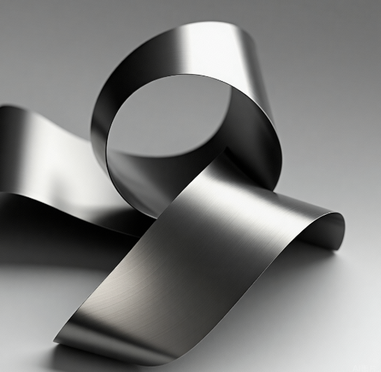
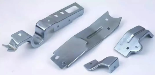
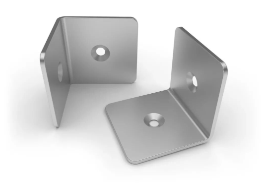
உங்கள் வாகனத்தை ஒன்றாக வைத்திருக்கும் தாங்கிகள் அல்லது தொழில்துறை உபகரணங்களைப் பாதுகாக்கும் சட்டங்கள் போன்றவை எவ்வாறு இரும்புத் தகடுகளிலிருந்து உருவாகின்றன என்று நீங்கள் யோசித்திருக்கிறீர்களா? இதற்கான விடை உலோக வடிவமைப்பில் வளைத்தலில் அடங்கியுள்ளது—இது நவீன வடிவமைப்பில் மிகவும் அடிப்படையானதும், பரவலாகப் பயன்படுத்தப்படும் தயாரிப்பு செயல்முறைகளில் ஒன்றாகும். நவீன வடிவமைப்பில் பயன்படுத்தப்படும் மிகவும் அடிப்படையானதும், பரவலாகப் பயன்படுத்தப்படும் தயாரிப்பு செயல்முறைகளில் ஒன்று. .
அடிப்படையில், உலோகத்தை வளைத்தல் என்பது ஒரு நேரான அச்சைச் சுற்றியுள்ள பொருளை விறைப்பாக்குதல் ஆகும். வளைவின் உள்புறத்தில் உள்ள உலோகம் சுருங்குகிறது, அதே நேரத்தில் வெளிப்புறத்தில் உள்ள உலோகம் நீண்டுகிறது. கருவிகள் மூலம் பயன்படுத்தப்படும் விசை பொருளின் விடுபடு விளிம்பை மீறும்போது, ஒரு அற்புதமான நிகழ்வு நிகழ்கிறது: தகடு பிளாஸ்டிக் மாற்றத்திற்கு உள்ளாகி, நிரந்தரமான வளைவை ஏற்றுக்கொள்கிறது. பென்ன் ஸ்டேட் பல்கலைக்கழகத்தின் பொறியியல் அறிவியல் துறையினர் மேற்கொண்ட ஆய்வுகளின்படி, இந்த நிரந்தர மாற்றம் ஏற்படுவதற்கு காரணம், மாற்றத்தை ஏற்படுத்தும் தன்மையில் உள்ள தன்மைகள் உலோகத்தை அதன் நெகிழ்வு வரம்பை மீறச் செய்வதே ஆகும்.
உலோக மாற்றத்தின் இயக்கவியல்
உலோகத்தை சரியாக வளைப்பதைப் புரிந்துகொள்ள அதில் செயல்படும் இயந்திரவியல் கோட்பாடுகளை அறிந்திருத்தல் அவசியம். தகடு வடிவிலான உலோகத்தின் மீது விசையைச் செலுத்தும்போது, இரண்டு வகையான மாறுபாடுகள் ஒரே நேரத்தில் ஏற்படுகின்றன:
- நெகிழ்வு மாறுபாடு — விசை நீக்கப்பட்ட பின் மீண்டும் முன்னைய நிலைக்குத் திரும்பும் தற்காலிக மாறுபாடு
- பிளாஸ்டிக் வடிவ மாற்றம் — சுமை நீக்கப்பட்ட பின்னும் பராமரிக்கப்படும் வடிவத்தின் நிரந்தர மாற்றம்
எந்தவொரு உலோக வடிவமைப்பு செயல்முறையிலும் நோக்கம், நெகிழ்வு பகுதியைக் கடந்து பிளாஸ்டிக் பகுதிக்குள் செல்வதாகும். இது தேவையான நிரந்தர கோணம் அல்லது வளைவை உருவாக்குகிறது, மேலும் பொருளின் கட்டமைப்பு ஒருமைப்பாட்டையும் பராமரிக்கிறது. நடுநிலை அச்சு — வளைவின் வழியாகச் செல்லும் ஒரு கற்பனைக் கோடு, அதில் பொருள் நீண்டிருக்கவோ அல்லது சுருங்கிருக்கவோ இல்லை — துல்லியமான வளைவு அளவுகளைக் கணக்கிடுவதில் முக்கிய பங்கு வகிக்கிறது.
பிளாஸ்டிக் மாறுபாடு என்பது, அதை ஏற்படுத்திய தன்மையின் விசைகள் நீக்கப்பட்ட பின்னும் வளைவு நிரந்தரமாக நிலைத்திருக்குமாறு ஏற்படும் மாறுபாடாகும். இந்தக் கோட்பாடு, பொருள் மீண்டும் தனது முந்தைய வடிவத்திற்குத் திரும்பிவிடும் (ஸ்பிரிங்-பேக்) தோல்வியுற்ற முயற்சிகளிலிருந்து, வெற்றிகரமான வளைத்தலை வேறுபடுத்துகிறது.
தகடு உலோகத்தை வளைக்கும்போது, நீங்கள் உண்மையில் ஒரு கட்டுப்படுத்தப்பட்ட சமநிலையை உருவாக்குகிறீர்கள். மிகக் குறைந்த விசையைச் செலுத்தினால், பொருள் திரும்பி வரும். ஏற்ற கருவியமைப்பு இன்றி மிகையான விசையைச் செலுத்தினால், பணிப்பொருளில் பிளவு ஏற்படுவதோ அல்லது அதன் வலிமை குறைவதோ நிகழ வாய்ப்புள்ளது.
தகடு உலோக வடிவமைப்பில் வளைத்தல் ஏன் ஆதிக்கம் செலுத்துகிறது
உலோகத்தை வளைத்தல் ஆட்டோமொபைல், விமான மற்றும் விண்வெளி, ஆற்றல் மற்றும் ரோபோட்டிக்ஸ் துறைகளில் உள்ள தயாரிப்பாளர்களுக்கு முதன்மையான செயல்முறையாக மாறிவிட்டது. ஆனால், ஏன் இந்த உலோக வடிவமைப்பு முறை மற்ற மாற்று முறைகளை விட ஆதிக்கம் செலுத்துகிறது?
பொருளை அகற்றும் வெட்டுதல் செயல்பாடுகள் அல்லது வெப்ப-பாதிக்கப்பட்ட மண்டலங்களை உருவாக்கும் காய்ச்சல் போன்றவற்றிலிருந்து மாறுபட்டு, வளைத்தல் பணிப்பொருள் முழுவதும் மூலப் பொருளின் பண்புகளைப் பாதுகாக்கிறது. இது கட்டமைப்பு கூறுகளுக்கு மிகவும் முக்கியமானது, ஏனெனில் தொடர்ச்சியான வலிமை மற்றும் தன்மை பாதுகாப்பு மற்றும் செயல்திறனை தீர்மானிக்கின்றன.
வளைத்தலை அவசியமாக்கும் இந்த நன்மைகளைக் கவனியுங்கள்:
- பொருள் செலுத்தம் — அகற்றுதல் செயல்பாடுகளிலிருந்து பொருள் வீணாதல் இல்லை
- வேகம் — நவீன அழுத்த வளைவு இயந்திரங்கள் வினாடிகளிலேயே சிக்கலான வளைவுகளை உருவாக்க முடியும்
- பண்பு பாதுகாப்பு — துகள் அமைப்பு மற்றும் மேற்பரப்பு முறைமை பெரும்பாலும் அப்படியே பாதுகாக்கப்படுகின்றன
- செலவு-செயல்திறன் — ஸ்டாம்பிங் அல்லது ஆழமான இழுத்தல் செயல்பாடுகளுடன் ஒப்பிடும்போது எளிமையான கருவிகள்
3ERP நிறுவனத்தின் தொழில் வல்லுநர்களின் கூற்றுப்படி, எஃகு, ஸ்டெயின்லெஸ் ஸ்டீல், அலுமினியம், துத்தநாகம் மற்றும் தாமிரம் போன்ற பொதுவான தகடு உலோகங்கள் பொதுவாக 0.006 முதல் 0.25 அங்குலம் வரையிலான தடிமனில் கிடைக்கின்றன. மெல்லிய தடிமன் கொண்ட தகடுகள் அதிக வளைவுத்தன்மையையும், வளைக்க எளிதானவையும் ஆகும்; அதேசமயம், அதிக வலுவை தேவைப்படும் கனரக பயன்பாடுகளுக்கு தடிமனான பொருள்கள் ஏற்றவை.
நீங்கள் V-வடிவங்கள், U-வடிவங்கள் அல்லது 120 டிகிரி வரையிலான சேனல்களை உருவாக்குகிறீர்கள் எனில், இந்த அடிப்படைக் கோட்பாடுகளை புரிந்துகொள்வது ஸ்பிரிங்பேக் ஈடுசெய்தல் மற்றும் K-காரணி கணக்கீடு போன்ற மேம்பட்ட சவால்களை எதிர்கொள்ள அடித்தளம் அமைக்கிறது — இவை அனுபவம் வாய்ந்த தகடு வேலை செய்பவர்களையும் குழப்பும் தலைப்புகள்.
முக்கிய வளைத்தல் முறைகள் – ஒப்பீடு
இப்போது உலோக வடிவ மாற்றத்தின் இயக்கவியலை நீங்கள் புரிந்துகொண்டுவிட்டீர்கள்; அதனால் ஒரு முக்கியமான கேள்வி எழுகிறது: உண்மையில் நீங்கள் எந்த வளைத்தல் செயல்முறையைப் பயன்படுத்த வேண்டும்? இதன் பதில் உங்கள் துல்லியத் தேவைகள், உற்பத்தி அளவு மற்றும் பொருளின் பண்புகளைப் பொறுத்தது. தகடு உலோக வடிவமைப்பில் கிடைக்கும் வித்தியாசமான வடிவமைப்பு முறைகளில், மூன்று முறைகள் அச்சு வளைவு இயந்திரங்களில் ஆதிக்கம் செலுத்துகின்றன — இவை ஒவ்வொன்றும் உங்கள் இறுதி லாபத்தை நேரடியாகப் பாதிக்கும் வகையில் தனித்தன்மை வாய்ந்த பரிமாற்றங்களைக் கொண்டவை.
தவறான தொழில்நுட்பத்தைத் தேர்வுசெய்வது அதிகப்படியான ஸ்பிரிங்பேக் (springback), முறையற்ற கருவிகளின் தீவிர அரிப்பு அல்லது தர வரம்புக்கு ஏற்றவாறு இல்லாத பாகங்களை ஏற்படுத்தும். உங்கள் குறிப்பிட்ட பயன்பாடுகளுக்கு தகுந்த முடிவுகளை எடுக்க வைக்க, காற்று வளைத்தல் (Air Bending), அடிப்பகுதி வளைத்தல் (Bottoming) மற்றும் நாணய வடிவமைத்தல் (Coining) ஆகியவற்றை விரிவாக ஆராய்வோம்.
பல்துறை உற்பத்திக்கான காற்று வளைத்தல்
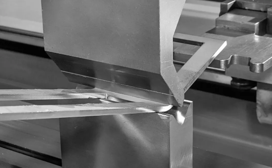
காற்று வளைத்தல் மூலம் தட்டு உலோகத்தை வளைத்தல் இன்று அச்சு விரிப்பான் (பிரெஸ் பிரேக்) மூலம் உருவாக்கும் மிகவும் பொதுவான முறையாக மாறிவிட்டது, அதற்கு நல்ல காரணங்களும் உள்ளன. இந்த வளைத்தல் முறையானது, உங்களுக்கு தேவையான கோணத்தை அடைய பொருளை டை (die) உள் தேவையான அளவு மட்டுமே தள்ளுவதன் மூலம் செயல்படுகிறது— மேலும் ஸ்பிரிங்பேக் (springback) ஐ ஈடுகட்ட கணக்கிடப்பட்ட அளவு கூடுதலாகவும். பஞ்ச் (punch), டை-க்கு முழுமையாக அடித்து விடுவதில்லை; இதனால் பணிப்பொருளின் கீழே காற்று இடைவெளி ஒன்று ஏற்படுகிறது.
இது ஏன் முக்கியம்? இந்த நடைமுறை நன்மைகளை கவனியுங்கள்:
- தள்ளு விசை (tonnage) தேவைகளில் குறைவு — பாட்டமிங் (bottoming) அல்லது காய்னிங் (coining) ஐ விட பொதுவாக 50–60% குறைந்த விசை தேவைப்படும்
- கருவிகளின் பன்முகத்தன்மை — 85-டிகிரி டை ஒன்றே பல்வேறு வளைவு கோணங்களை அடைய உதவும்
- குறைந்த முதலீட்டு செலவுகள் — பல்வேறு உற்பத்தி தேவைகளுக்கு குறைந்த எண்ணிக்கையிலான கருவித் தொகுப்புகள் தேவை
- பொருளுடன் குறைந்த தொடர்பு — மேற்பரப்பு குறியீடுகள் மற்றும் கருவிகளின் தேய்வு குறைவு
காற்று வளைத்தலின் நெகிழ்வுத்தன்மை பல்வேறு வேலைகளைக் கையாளும் வேலை நிலையங்களுக்கு மிகவும் ஏற்றதாகும். ராம் ஆழத்தை எளிதில் சரிசெய்வதன் மூலம் ஒரே பஞ்ச் மற்றும் டை கலவையைப் பயன்படுத்தி 90-டிகிரி, 120-டிகிரி அல்லது கூர் கோணங்களை உருவாக்க முடியும். இருப்பினும், இந்த முறை மாறான முடிவுகளை அடைய துல்லியமாக நிலைநிறுத்தப்பட்ட இயந்திரம் மற்றும் துல்லியமாக தீட்டப்பட்ட கருவிகளை தேவைப்படுத்துகிறது.
இதன் பரிமாற்றம் என்ன? காற்று வளைத்தலில் பொருள் இறுதி வடிவத்தில் பதிய குறைந்த விசை பயன்படுத்தப்படுவதால், ஸ்பிரிங்பேக் (திரும்பும் விளைவு) மிகவும் தெளிவாக தெரியும். நவீன CNC பிரெஸ் பிரேக்குகள் தாமாகவே இதை ஈடுசெய்கின்றன, ஆனால் வளைத்தல் வரிசைகளை நிரலாக்கும்போது இந்த நடத்தையை கணக்கில் எடுத்துக்கொள்ள வேண்டும்.
துல்லியம் தளத்தில் வளைத்தல் அல்லது காய்ணிங் தேவைப்படும்போது
சில சமயங்களில், காற்று வளைத்தலின் நெகிழ்வுத்தன்மை போதுமானதாக இருக்காது. உங்கள் தகடு உலோக வளைத்தல் முறைகள் குறுகிய சுழற்சிகளை (tolerances) வழங்க வேண்டும் அல்லது மிக அதிக ஸ்பிரிங்பேக் ஏற்படும் பொருள்களுடன் பணியாற்றும்போது, தளத்தில் வளைத்தல் (bottoming) மற்றும் காய்ணிங் (coining) வளைத்தல் முறைகள் பயன்படுத்தப்படுகின்றன.
அடிப்பகுதி வளைத்தல் உலோகத்தை V-வடிவ டையில் முழுமையாக அழுத்தி, டையின் மேற்பரப்புகளுடன் முழுமையான தொடர்பை ஏற்படுத்துகிறது. இந்த முறை காற்று வளைத்தலை விட அதிக டன் திறனை தேவைப்படுத்துகிறது, ஆனால் ஒரு முக்கிய நன்மையை வழங்குகிறது: இறுதி கோணத்தை கட்டுப்படுத்துவது ராம் நிலை மட்டுமல்ல, கருவியமைப்பின் வடிவமைப்பும் ஆகும். தென் ஃபேப்ரிகேட்டிங் மெஷினரி சேல்ஸ் என்பதன்படி, துல்லியமான நிலையமைப்பை விட கருவித் தொகுப்பிலிருந்து துல்லியம் பெறப்படும் இயந்திர அழுத்த வளைவு இயந்திரங்களில் அடிப்பகுதி வளைத்தல் (பாட்டம் பெண்டிங்) இன்றும் பொதுவான நடைமுறையாகவே உள்ளது.
அடிப்பகுதி வளைத்தலிலும் ஸ்பிரிங்பேக் ஏற்படுகிறது, ஆனால் அது காற்று வளைத்தலை விட முன்கூட்டியே கணிக்கக்கூடியதாகவும், குறைவாகவும் இருக்கும். எனவே இது பின்வரும் பயன்பாடுகளுக்கு ஏற்றது:
- ஒரே கோணத்தை தொடர்ந்து உற்பத்தி செய்ய வேண்டிய உற்பத்தி ஓட்டங்கள்
- கருவிகளில் முதலீடு செய்வது உற்பத்தி அளவுக்கு ஏற்றதாக இருக்கும் பயன்பாடுகள்
- மிதமான ஸ்பிரிங்பேக் பண்புகளைக் கொண்ட பொருட்கள்
நாணய வளைப்பு விசித்திரமான விசையை அதிகபட்சமாகக் கொண்டு செல்கிறது. இந்த வார்த்தை நாணயங்களை உருவாக்கும் செயல்முறையிலிருந்து வந்தது, அங்கு மிகப்பெரிய அழுத்தம் துல்லியமான அச்சுகளை உருவாக்குகிறது. தகடு உலோக வேலையில், காய்னிங் (coining) என்பது பொருளை டை (die) அடிப்பகுதிக்குள் தள்ளி, பின்னர் கூடுதலாக 10-15% விசையைச் செலுத்துகிறது, இதனால் உலோகம் உண்மையில் நொறுங்கி, டையின் துல்லியமான கோணத்தை நிலைநிறுத்துகிறது.
இந்த முறை மற்ற வகையான வளைத்தல் செயல்முறைகளை விட 3X முதல் 5X வரை டானேஜ் (tonnage) ஐ தேவைப்படுத்துகிறது — இது உபகரண திறன் மற்றும் ஆற்றல் செலவுகளுக்கு முக்கியமான கருத்தாகும். எனினும், நீங்கள் ஆயிரக்கணக்கான பாகங்களில் திட்டவட்டமாக பூஜ்ஜிய ஸ்பிரிங்பேக் (springback) மற்றும் துல்லியமான மீள்தன்மையை தேவைப்படுத்தும்போது, காய்னிங் சிறந்த தீர்வை வழங்குகிறது.
முடிவெடுப்பதற்கான கட்டமைப்பு: உங்கள் முறையைத் தேர்வு செய்தல்
சரியான வளைத்தல் செயல்முறையைத் தேர்வு செய்வது பல காரணிகளைச் சமன் செய்வதை நோக்கமாகக் கொண்டது. பின்வரும் ஒப்பீடு உங்கள் குறிப்பிட்ட தேவைகளுக்கு ஏற்றவாறு ஒவ்வொரு முறையையும் மதிப்பீடு செய்வதற்கு உதவுகிறது:
| அளவுரு | ஏர் பெண்டிங் | அடிப்பகுதி வளைத்தல் | காய்னிங் |
|---|---|---|---|
| விசை தேவைகள் | மிகக் குறைந்த (அடிப்படை) | மிதமானது (1.5-2X ஏர் பெண்டிங்) | அதிகபட்சம் (3-5X ஏர் பெண்டிங்) |
| ஸ்பிரிங்பேக் அளவு | மிகவும் முக்கியமான | குறைந்த | குறைந்தபட்சம் அல்லது எதுவுமில்லை |
| கருவிகளின் தேய்வு | குறைந்த தொடர்பு, நீண்ட ஆயுள் | மிதமான தேய்மானம் | அதிகபட்ச தேய்மானம், அடிக்கடி மாற்றம் |
| துல்லிய தரம் | ±0.5° வழக்கமானது | ±0.25° அடையக்கூடியது | ±0.1° அல்லது அதற்கு மேற்பட்டது |
| கருவி முதலீடு | குறைவு (பல்துறை தொகுப்புகள்) | நடுத்தரம் (கோணத்திற்கு குறிப்பிட்ட) | அதிகம் (கோணத்திற்கு ஏற்றவாறு பொருத்தப்பட்ட தொகுப்புகள்) |
| நல்ல பயன்பாடுகள் | வேலை கடைகள், முன்மாதிரி உருவாக்கம், மாறுபட்ட உற்பத்தி | நடுத்தர அளவு உற்பத்தி, இயந்திர அழுத்த வளைவு சாதனங்கள் | அதிக துல்லியம் கொண்ட பாகங்கள், விண்வெளி துறை, கடுமையான துல்லியத் தேவைகளைக் கொண்ட கூட்டு அமைப்புகள் |
உங்கள் பொருளின் பண்புகளும் முறை தேர்வை பாதிக்கின்றன. மென்மையான எஃகு மற்றும் அலுமினியம் போன்ற செலுத்தக்கூடிய உலோகங்கள் இம்மூன்று அணுகுமுறைகளையும் ஏற்றுக்கொள்ளும், அதே நேரத்தில் குறிப்பிடத்தக்க ஸ்பிரிங்பேக் (springback) கொண்ட அதிக வலிமை கொண்ட கலவைகள் பொதுவாக பாட்டமிங் (bottoming) அல்லது காய்னிங் (coining) ஆகியவற்றிலிருந்து நன்மை பெறும். உங்கள் தகடு உலோகத்தின் தடிமன், விறைப்பு மற்றும் ஸ்பிரிங்பேக் பண்புகள் இறுதியில் கோணத் தேவைகள் மற்றும் உற்பத்தி அளவுடன் இணைந்து உங்கள் முடிவை வழிநடத்தும்.
இந்த வேறுபாடுகளைப் புரிந்துகொள்வது, உலோக வடிவமைப்பில் மிகவும் சிரமமான சவால்களில் ஒன்றான ஸ்பிரிங்பேக்கை ஈடுசெய்வதை நீங்கள் எதிர்கொள்ள உதவும். வளைத்தல் போது வெவ்வேறு பொருள்கள் எவ்வாறு நடந்துகொள்கின்றன என்பதையும், அது உங்கள் வளைவு ஆரை (bend radius) தன்மைகளுக்கு என்ன பொருள் தருகிறது என்பதையும் ஆராய்வோம்.
பொருள் தேர்வு மற்றும் வளைத்தல் நடத்தை
நீங்கள் உங்கள் வளைத்தல் முறையைத் தேர்ந்தெடுத்துவிட்டீர்கள்—ஆனால் பெரும்பாலான தயாரிப்பாளர்கள் குறைத்து மதிப்பிடும் சவால் இதுதான்: ஒரே தொழில்நுட்பம், உங்கள் பொருளைப் பொறுத்து முற்றிலும் வேறுபட்ட முடிவுகளை உருவாக்கும். மென்மையான எஃகிற்கு சரியாக வேலை செய்யும் ஒரு வளைவு ஆரம், அலுமினியத்தில் பிளவுகளை ஏற்படுத்தலாம் அல்லது ஸ்டெயின்லெஸ் ஸ்டீலில் கணிசமாக மீண்டு வரலாம். வளைக்கக்கூடிய பல்வேறு உலோகத் தகடுகள் வடிவமாற்றத்தின் போது எவ்வாறு நடந்துகொள்கின்றன என்பதைப் புரிந்துகொள்வதுதான், வெற்றிகரமான திட்டங்களையும், செலவு அதிகமான தோல்விகளையும் பிரிக்கிறது.
வளைக்கக்கூடிய ஒவ்வொரு உலோகமும் அச்சு பிரேக்கில் தனித்துவமான பண்புகளைக் கொண்டுள்ளது . விளைவு வலிமை, நெகிழ்வுத்தன்மை, வேலை கடினமாகும் போக்கு மற்றும் துகள் அமைப்பு ஆகியவை அந்த குறிப்பிட்ட பொருளை எவ்வளவு கடுமையாக வடிவமைக்க முடியும் என்பதை எல்லாம் பாதிக்கின்றன. பொதுவாகப் பயன்படுத்தப்படும் தகடு உலோகங்களுடன் நீங்கள் எதிர்கொள்ளப்போகும் குறிப்பிட்ட நடத்தைகளை ஆராய்வோம்.
அலுமினியம் மற்றும் மென்மையான உலோகங்களின் வளைத்தல் பண்புகள்
அலுமினியம் தகட்டை வளைத்தல் அதன் வடிவமைப்புத் திறனுக்கான புகழைக் கருதி எளிதாகத் தோன்றலாம்—ஆனால் குறுகிய ஆரங்களில் பிளவுகள் ஏற்படும் வரை. உண்மை என்னவென்றால், பல இயக்கியாளர்கள் எதிர்பார்ப்பதைவிட இது மிகவும் சிக்கலானது.
அலுமினியம் கலவைகள் அவற்றின் வளைதல் நடத்தையில் குறிப்பிடத்தக்க மாறுபாடுகளைக் கொண்டுள்ளன. 3003-H14 அல்லது 5052-H32 போன்ற மென்மையான வகைகள் பெரிய வளைவு ஆரங்களுடன் எளிதில் வளைகின்றன, அதே நேரத்தில் 6061-T6 போன்ற வெப்பச் சிகிச்சை பெற்ற கலவைகள் கூடுதல் எச்சரிக்கையை தேவைப்படுத்துகின்றன. என்பதன்படி, புரோட்டோலேப்ஸ் 6061-T6 அலுமினியம் சிறிது உடையக்கூடிய தன்மையைக் கொண்டுள்ளது, எனவே பிற பொருட்களுடன் ஒப்பிடும்போது பிளவுகளைத் தடுக்க பெரிய வளைவு ஆரங்கள் தேவைப்படலாம்.
அலுமினியம் மற்றும் பிற மென்மையான உலோகங்களுடன் பணியாற்றும்போது, பொருளின் தடிமனை ஒப்பிடும்போது இந்த குறைந்தபட்ச வளைவு ஆர வழிகாட்டுதல்களைக் கவனத்தில் கொள்ளவும்:
- 1100 மற்றும் 3003 அலுமினியம் (மென்மையாக்கப்பட்டது) — 0T முதல் 1T வரை (மென்மையாக்கப்பட்ட நிலையில் பூஜ்ஜிய ஆரத்திற்கு வளைக்க முடியும்)
- 5052-H32 அலுமினியம் — 1T முதல் 1.5T வரை குறைந்தபட்ச வளைவு ஆரம்
- 6061-T6 அலுமினியம் — 1.5T முதல் 2T வரை குறைந்தபட்ச வளைவு ஆரம் (முக்கிய பயன்பாடுகளுக்கு பெரிய ஆரம் பரிந்துரைக்கப்படுகிறது)
- தாமிரம் (மென்மையான) — 0T முதல் 0.5T வரை (சிறந்த வடிவமைப்புத் திறன்)
- எஃகு (அரை-கடினம்) — 0.5T முதல் 1T வரை குறைந்தபட்ச வளைவு ஆரம்
தனிம வடிவமைப்பு திறனில் சிறந்து விளங்கும் தாமிரக் கலவைகள் குறிப்பிடத்தக்கவை. மென்மையான தாமிரம் மிகக் குறைந்த ஸ்பிரிங்பேக் (springback) உடன் எளிதாக வளைக்கப்படுகிறது, இது மின்சார அடைப்புகள் மற்றும் அலங்கார வளைந்த தகடு உலோகப் பயன்பாடுகளுக்கு மிகவும் ஏற்றது. பிராஸ் (brass) சிறிது அதிக எதிர்ப்பை வழங்குகிறது, ஆனால் கட்டிடக்கலை மற்றும் குழாய் பாகங்களுக்கான உற்பத்தியில் இன்னும் மிகவும் வேலை செய்யக்கூடியதாகவே உள்ளது.
அலுமினியத்தில் வளைக்கக்கூடிய தகடு செயல்திறனை தானிய திசை (grain direction) மிகவும் முக்கியமாகப் பாதிக்கிறது. உருட்டுதலின் திசைக்குச் செங்குத்தாக (தானியத்திற்கு குறுக்காக) வளைத்தல் பிளவு ஏற்படுவதற்கான அபாயத்தைக் குறைக்கிறது, அதே நேரத்தில் தானியத்திற்கு இணையாக வளைத்தல் விரிச்சல் ஏற்படுவதற்கான வாய்ப்பை அதிகரிக்கிறது — குறிப்பாக கடினமான வெப்ப நிலைகளில் (harder tempers). பல வளைவுகளை தேவைப்படும் பாகங்களை வடிவமைக்கும்போது, முக்கிய வளைவுகள் தானியத்திற்கு குறுக்காக அமையுமாறு உங்கள் வெட்டுகளை (blanks) சரியான திசையில் அமைக்கவும்.
ஸ்டெயின்லெஸ் ஸ்டீல் மற்றும் உயர் வலிமை கலவைகளுடன் பணிபுரிதல்
ஸ்டெயின்லெஸ் ஸ்டீல் தகடுகளை வளைத்தல் முற்றிலும் வேறுபட்ட சவாலை ஏற்படுத்துகிறது: குறிப்பிடத்தக்க ஸ்பிரிங்பேக் (springback) மற்றும் விரைவான வேலை கடினமாதல் (rapid work hardening) ஆகிய இரண்டும் கார்பன் ஸ்டீல் அல்லது அலுமினியத்தை விட மாற்றப்பட்ட அணுகுமுறைகளைத் தேவைப்படுத்துகின்றன.
ஸ்டெயின்லெஸ் ஸ்டீலின் ஸ்பிரிங்பேக் 10–15 டிகிரி அல்லது அதற்கு மேற்பட்டதாக இருக்கலாம், இது படிக்கட்டு மற்றும் தடிமனைப் பொறுத்து மாறுபடும்—இது மென்மையான ஸ்டீலின் பொதுவான 2–4 டிகிரி ஸ்பிரிங்பேக்கை விட கணிசமாக அதிகம். இந்த பொருளின் உயர் யீல்டு வலிமை காரணமாக, வளைத்தல் போது அதிக நெகிழ்வு ஆற்றல் சேமிக்கப்படுகிறது, இது கருவிகள் பின்வாங்கும்போது வெளியிடப்படுகிறது. 304 மற்றும் 316 போன்ற ஆஸ்டெனிட்டிக் படிக்கட்டுகள் விரைவாக வேலை வலிமையை அடைகின்றன, எனவே ஒரே பகுதியில் மீண்டும் மீண்டும் வளைத்தல் அல்லது சரிசெய்தல் பிளவுகளுக்கு வழிவகுக்கும்.
எஃகு கலவைகளுக்கான குறைந்தபட்ச வளைவு ஆரத்தின் பரிந்துரைகள் பின்வருமாறு:
- மென்மையான ஸ்டீல் (1008–1010) — 0.5T முதல் 1T வரை (கணிசமான நடத்தை, மிதமான ஸ்பிரிங்பேக்)
- அதிக வலிமை குறைந்த கலவை எஃகு — 1T முதல் 1.5T வரை குறைந்தபட்ச வளைவு ஆரம்
- 304 உலோகம் என்னும் உலோகம் — 1T முதல் 2T வரை (கணிசமான ஸ்பிரிங்பேக் ஈடுசெய்தல் தேவைப்படும்)
- 316 ஸ்டெயின்லெஸ் ஸ்டீல் — 1.5T முதல் 2T வரை குறைந்தபட்ச ஆரம்
- கடினமாக்கப்பட்ட ஸ்பிரிங் ஸ்டீல் — 2T முதல் 4T வரை (அதிக ஸ்பிரிங்பேக், குறைந்த வடிவமைப்புத் திறன்)
கார்பன் ஸ்டீல் என்பது இரும்பு கலவைகளில் மிகவும் கணிக்கத்தக்க வளைவு நடத்தையை வழங்குகிறது, இது அடிப்படை அளவுகளை நிர்ணயிப்பதற்கான தரத்தை ஏற்படுத்துகிறது. மென்மையான தரத்தில் உள்ள வளைக்கக்கூடிய ஸ்டீல் தகடு கணக்கிடப்பட்ட ஸ்பிரிங்பேக் ஈடுசெய்தலுக்கு ஒழுங்கான முறையில் பதிலளிக்கிறது மற்றும் ஸ்டெயின்லெஸ் ஸ்டீல் மாற்றுகளை விட குறைந்த வளைவு ஆரங்களை ஏற்றுக்கொள்கிறது.
அனீலிங் (வெப்பசிகிச்சல்) என்பது அனைத்து உலோக வகைகளிலும் உள் மன அழுத்தங்களை நீக்கி, தானிய அமைப்பை மென்மையாக்குவதன் மூலம் வளைவுத்தன்மையை குறிப்பிடத்தக்க அளவில் மேம்படுத்துகிறது. ஸ்டெயின்லெஸ் ஸ்டீலுக்கு, வளைவதற்கு முன் அனீலிங் செய்வது ஸ்பிரிங்பேக்கை 30-40% வரை குறைக்கலாம் மற்றும் பிளவு ஏற்படாமல் குறைந்த வளைவு ஆரங்களை அனுமதிக்கலாம். எனினும், இது செயலாக்க நேரத்தையும் செலவையும் அதிகரிக்கிறது — இது உங்கள் துல்லியத் தேவைகளுக்கு எதிராக மதிப்பீடு செய்யப்பட வேண்டிய ஒரு வரையறுத்த பரிமாற்றமாகும்.
தடிமன் வரம்புகள் பொருளின் வகையைப் பொறுத்து மாறுபடுகின்றன, பொதுவான வழிகாட்டுதல்களின்படி, பொருளின் வலிமை அதிகரிக்கும் போது அதிகபட்ச வளைக்கக்கூடிய தடிமன் குறைகிறது. மென்மையான ஸ்டீல் 0.25 அங்குலம் தடிமனில் சுத்தமாக வளைக்கப்படலாம் எனினும், அதே செயல்பாடு ஸ்டெயின்லெஸ் ஸ்டீலில் சிறப்பு சாதனங்கள் அல்லது பல வடிவமைப்பு நிலைகளை தேவைப்படுத்தலாம்.
பொருளின் செயல்பாட்டைப் புரிந்துகொண்ட பிறகு, இந்தப் பண்புகளை துல்லியமான தட்டை வடிவங்களாக (flat patterns) மாற்றும் கணக்கீடுகளைச் செய்வதற்கு நீங்கள் தயாராகிவிட்டீர்கள்—முதலில் வளைவு அனுமதி (bend allowance) மற்றும் பெரும்பாலும் தவறாகப் புரிந்துகொள்ளப்படும் K-காரணி (K-factor) ஆகியவற்றிலிருந்து தொடங்கி.
வளைவு அனுமதி மற்றும் K-காரணி கணக்கீடுகள் விளக்கப்பட்டுள்ளன
பல உற்பத்தியாளர்கள் இங்கு ஒரு சுவரைச் சந்திக்கின்றனர்: நீங்கள் உங்கள் பொருளைத் தேர்ந்தெடுத்துள்ளீர்கள், உங்கள் வளைவு முறையைத் தேர்ந்தெடுத்துள்ளீர்கள், மேலும் உங்கள் வளைவு ஆரத்தை குறிப்பிட்டுள்ளீர்கள்—ஆனால் முடிவில் உருவாக்கப்பட்ட பாகம் மிக நீளமாகவோ அல்லது மிகக் குறுகியதாகவோ வருகிறது. இது உங்களுக்கு பரிச்சயமானதாக இருக்கிறதா? இதற்கு முக்கிய காரணம் பெரும்பாலும் தவறான வளைவு அனுமதி கணக்கீடுகளே; இந்தக் கணக்கீடுகளின் மையத்தில் K-காரணி அமைந்துள்ளது.
தகடு உலோகத்தை (sheet metal) துல்லியமாக எவ்வாறு வளைப்பது என்பதைப் புரிந்துகொள்ள இந்தக் கருத்துகளை வல்லவராக இருத்தல் அவசியம். இவற்றை இல்லாமல், நீங்கள் தட்டை வடிவங்களின் அளவுகளை ஊகித்துக் கொண்டே இருக்கிறீர்கள்—இது பொருள் வீணாதல் மற்றும் மீண்டும் வேலை செய்ய வேண்டிய தேவை ஆகியவை உற்பத்தி ஓட்டங்களில் தொடர்ந்து அதிகரிக்கும் போது, இது செலவு அதிகரிப்பை ஏற்படுத்தும் ஒரு முறையாகும்.
வளைத்தலில் நடுநிலை அச்சு (Neutral Axis) பற்றிய புரிதல்
முன்பு நாம் குறிப்பிட்ட நியமன அச்சு (neutral axis) என்பதை நினைவில் கொள்ளுங்கள்? இது வளைத்தல் செயல்முறையில் அனைத்திற்கும் முக்கியமானது. தகடு உலோகம் (sheet metal) வளைக்கப்படும்போது, வெளிப்புற மேற்பரப்பு நீண்டு செல்கிறது, அதே நேரத்தில் உள்புற மேற்பரப்பு சுருங்குகிறது. இந்த இரண்டு அதிர்ச்சிகர நிலைகளுக்கு இடையில், எந்தவொரு நீட்சியும் அல்லது சுருக்கமும் ஏற்படாத ஒரு கற்பனை தளம் உள்ளது—அதுதான் நியமன அச்சு.
ஜிடி-புரோட்டோடைப்பிங் (GD-Prototyping) நிறுவனத்தின் பொறியியல் ஆய்வுகளின்படி, வளைத்தல் செயல்பாடு நடைபெறும்போது நியமன அச்சின் நீளம் மாறாமல் நிலைத்து நிற்கிறது. வளைக்கப்படுவதற்கு முன்னர் அதன் நீளம், வளைத்த பின்னர் அதன் வளைவு நீளத்திற்கு சமமாக இருக்கும். எனவே, அனைத்து வளைத்தல் கணக்கீடுகளுக்கும் இதுதான் மிக முக்கியமான குறிப்பு அச்சு.
இது நடைமுறையில் ஏன் முக்கியமானது என்பதை இங்கே காணலாம்: துல்லியமான தட்டை வடிவத்தை (flat pattern) உருவாக்க, ஒவ்வொரு வளைத்தலின் வழியாக நியமன அச்சின் வளைவு நீளத்தைக் கணக்கிட வேண்டும். இந்தக் கணக்கிடப்பட்ட நீளம்—வளைத்தல் அனுமதி (bend allowance)—தட்டை பகுதிகளுடன் கூட்டப்பட்டு, மொத்த வடிவத்தின் நீளத்தைத் தீர்மானிக்கிறது.
நியமன அச்சு என்பது, மூன்று-பரிமாண வடிவமைக்கப்பட்ட பாகத்தையும், தயாரிப்புக்காகத் தேவையான இரு-பரிமாண தட்டை வடிவத்தையும் இணைக்கும் முக்கியமான இணைப்பு.
ஆனால், உங்கள் பொருளின் தடிமனுக்குள் நியூட்ரல் அச்சு எங்கே சரியாக அமைந்துள்ளது? இதற்குத்தான் K-காரணி (K-factor) பயன்படுகிறது. தகடு வளைத்தலுக்கான வாய்ப்பாடு இந்த அச்சின் சரியான இடத்தை அடிப்படையாகக் கொண்டுள்ளது.
K-காரணி என்பது உள் வளைவு மேற்பரப்பிலிருந்து நியூட்ரல் அச்சு வரையிலான தூரத்தை, மொத்த பொருளின் தடிமனால் வகுத்துக் கிடைக்கும் விகிதம் ஆகும்:
K = t / T
இங்கே:
- t = உள் மேற்பரப்பிலிருந்து நியூட்ரல் அச்சு வரையிலான தூரம்
- T = மொத்த பொருளின் தடிமன்
K-காரணி 0.50 ஆக இருந்தால், நியூட்ரல் அச்சு பொருளின் மையத்தில் சரியாக அமைந்திருக்கும். ஆனால், வளைத்தலின் சிக்கலான தன்மையால் ஏற்படும் பல்வேறு விசைகள் காரணமாக, நியூட்ரல் அச்சு உள் மேற்பரப்பை நோக்கி நகர்கிறது — அதாவது, K-காரணியின் மதிப்புகள் பொதுவாக பொருளின் வகை மற்றும் வளைத்தல் முறையைப் பொறுத்து 0.3 முதல் 0.5 வரை மாறுபடும்.
பயன்பாட்டு நிலையில் K-காரணியின் பயன்பாடு
எனவே, அளவுகளுக்கு ஏற்றவாறு தகடு வளைத்தல் எவ்வாறு செய்வது? முதலில், உங்கள் குறிப்பிட்ட சூழ்நிலைக்கு ஏற்ற K-காரணியைத் தேர்ந்தெடுங்கள். என்பதன்படி, ஆர்க்கேப்டனின் தொழில்நுட்ப வளங்கள் , வளைத்தல் முறையைப் பொறுத்து K-காரணியின் பொதுவான வரம்புகள் மாறுபடும்:
| வளைவு வகை | பொதுவான K-காரணி வரம்பு | குறிப்புகள் |
|---|---|---|
| ஏர் பெண்டிங் | 0.30 – 0.45 | மிகவும் பொதுவானது; ஆழம் துளைத்தலுடன் ஆரம் மாறும் |
| அடிப்பகுதி வளைத்தல் | 0.40 – 0.50 | கடுமையான கட்டுப்பாடு, குறைந்த சுருள் திரும்பும் விளைவு |
| காய்னிங் | 0.45 – 0.50 | அதிக அழுத்த விசைகள் நடு அச்சை மையத்தை நோக்கி நகர்த்துகின்றன |
சிறிய ஆரங்களுடன் கடுமையான வளைவுகள், மிகுந்த மாறுபாட்டின் கீழ் நடு அச்சு உள் பரப்பிற்கு அருகே நகர்வதால் K-காரணியை 0.3 ஐ நோக்கி தள்ளுகின்றன. பெரிய ஆரங்களுடன் மென்மையான வளைவுகள் K-காரணியை 0.5 ஐ நோக்கி நகர்த்துகின்றன. வழக்கமான மென்மையான எஃகுக்கு, பல தயாரிப்பாளர்கள் தொடக்கத்தில் 0.44 ஐ அடிப்படையாக எடுத்து, சோதனை முடிவுகளின் அடிப்படையில் அதனை திருத்துகின்றனர்.
உள் ஆரம் மற்றும் பொருளின் தடிமனுக்கு இடையேயான தொடர்பு (R/T விகிதம்) கூட K-காரணி தேர்வை பாதிக்கிறது. R/T விகிதம் அதிகரிக்கும் போது, K-காரணி அதிகரிக்கிறது—ஆனால் அதன் அதிகரிப்பு வீதம் குறைந்து கொண்டே செல்கிறது, மேலும் அந்த விகிதம் மிக அதிகமாகும்போது 0.5 என்ற எல்லையை நெருங்குகிறது.
படிப்படியான வளைவு அனுமதிப்பு கணக்கீடு
உங்கள் தகடு வளைவு அளவுகளைக் கணக்கிட தயாராக இருக்கிறீர்களா? வளைவு துல்லியத்தின் செயல்முறை இந்த வளைவு அனுமதிப்பு (bend allowance) சூத்திரத்திலிருந்து தொடங்குகிறது:
BA = (π ÷ 180) × A × (IR + K × T)
இங்கே:
- Ba = வளைவு அனுமதிப்பு (நடுப்புள்ளி அச்சின் வளைவு நீளம்)
- A = வளைவு கோணம் டிகிரிகளில் (வளைவின் கோணம், உள்ளடக்கிய கோணம் அல்ல)
- ஐர் = உள் ஆரம்
- K = K-காரணி
- T = பொருள் தடிமன்
துல்லியமான தட்டு வடிவங்களைப் பெற இந்த படிப்படியான கணக்கீட்டு முறையைப் பின்பற்றவும்:
- உங்கள் R/T விகிதத்தை நிர்ணயிக்கவும் — உள் வளைவு ஆரத்தை பொருளின் தடிமனால் வகுக்கவும். எடுத்துக்காட்டாக, 2 மிமீ தடிமன் கொண்ட பொருளில் 3 மிமீ ஆரம் கொண்ட வளைவு R/T = 1.5 ஐத் தரும்.
- ஏற்ற K-காரணியைத் தேர்ந்தெடுக்கவும் — R/T விகிதத்தையும் உங்கள் வளைத்தல் முறையையும் பயன்படுத்தி தரநிலை அட்டவணைகளிலிருந்து தேர்வு செய்யவும், அல்லது உங்கள் தொழிற்சாலையின் சோதனை வளைத்தல் தரவுகளைப் பயன்படுத்தவும்.
- வளைத்தல் அனுமதிப்பு (Bend Allowance) ஐக் கணக்கிடவும் — உங்கள் மதிப்புகளை BA சூத்திரத்தில் பிரதியிடவும். IR = 3 மிமீ, T = 2 மிமீ மற்றும் K = 0.42 ஆகியவற்றுடன் 90-டிகிரி வளைத்தலுக்கு: BA = (π/180) × 90 × (3 + 0.42 × 2) = 1.571 × 3.84 = 6.03 மிமீ.
- தட்டையான வடிவத்தின் நீளத்தை தீர்மானிக்கவும் — உங்கள் தட்டையான கால்களின் நீளங்களுடன் (வெளிப்புற அளவுகள் அல்ல, தாங்கென்ட் புள்ளிகளிலிருந்து அளக்கப்பட்டவை) வளைத்தல் அனுமதிப்பைச் சேர்க்கவும்.
- சோதனை வளைத்தல்களுடன் சரிபார்க்கவும் — உற்பத்தி ஓட்டங்களுக்கு முன்பாக எப்போதும் உண்மையான பொருள் மாதிரிகளுடன் கணக்கீடுகளை உறுதிப்படுத்தவும்.
ADH இயந்திர கருவியின் தொழில்நுட்ப ஆவணங்களின்படி, மிகச் சரியான K-காரணி என்பது உங்கள் சொந்த இயந்திரங்களில் செய்யப்பட்ட உண்மையான சோதனை வளைத்தல்களின் அடிப்படையில் மறுகணக்கிடுதல் மூலம் பெறப்படுகிறது; இதில் உங்கள் குறிப்பிட்ட கருவிகள் மற்றும் பொருள்கள் பயன்படுத்தப்படுகின்றன. வெளியிடப்பட்ட அட்டவணைகள் நியாயமான தொடக்கப் புள்ளிகளை வழங்குகின்றன, ஆனால் அவை தோராயமானவையே – இறுதியான மதிப்புகள் அல்ல.
வளைவு செயல்முறை கணக்கீடுகளை சரியாக செய்வது, சோதனை-மற்றும்-பிழை திருத்தங்களின் சிரமமான சுழற்சியை நீக்குகிறது. உங்கள் தட்டையான வடிவங்கள் இறுதி அளவுகளை துல்லியமாக முன்கூட்டியே கணிக்கும்போது, தவறான பாகங்களின் எண்ணிக்கையைக் குறைத்து, மீண்டும் செய்ய வேண்டிய பணியை குறைத்து, கூட்டுதல் போது பாகங்கள் சரியாக பொருந்துவதை உறுதிப்படுத்துகிறது. இந்த கணித வாய்ப்பாடுகளை புரிந்துகொள்ளும் சிறிய முதலீடு, ஒவ்வொரு உற்பத்தி ஓட்டத்திலும் பெரும் பயனை அளிக்கிறது.
நிச்சயமாக, முழுமையான கணக்கீடுகள் கூட ஒரு தொடர்ச்சியான சவாலை நீக்க முடியாது: வளைவை விடுவிக்கும்போது ஏற்படும் தன்மையின் நெகிழ்வு மீள்வு (எலாஸ்டிக் ரிகவரி). உங்கள் கோணங்களை பொருளின் நடத்தையை பொருட்படுத்தாமல் துல்லியமாக வைத்திருக்க உதவும் ஸ்பிரிங்பேக் ஈடுசெய்தல் முறைகளை இப்போது ஆராய்வோம்.
ஸ்பிரிங்பேக் ஈடுசெய்தல் நுட்பங்கள்
நீங்கள் உங்கள் வளைவு அனுமதிப்பை முறையாகக் கணக்கிட்டு, சரியான ஆழத்தை நிரல்படுத்தி, கால் பீடலை அழுத்தியுள்ளீர்கள்—ஆனால், ராம் திரும்பும்போது, உங்கள் 90-டிகிரி கோணம் 87 டிகிரி ஆக அளவிடப்படுகிறது. என்ன தவறு நடந்தது? உண்மையில், எதுவும் தவறில்லை. நீங்கள் வெறும் ஸ்பிரிங்பேக் (மீள்வு) எனப்படும், எந்த உலோக வளைவிலும் தவறாமல் ஏற்படும் நெகிழ்வு மீள்வை சந்தித்துள்ளீர்கள்.
இந்த நிகழ்வு தினசரி ஆபரேட்டர்களை பிரச்சனைக்கு உள்ளாக்குகிறது, ஏனெனில் பொருள் வடிவமைப்பிற்கு "எதிராக" செயல்படுவது போல் தோன்றுகிறது. ஸ்பிரிங்பேக் (springback) ஏன் ஏற்படுகிறது என்பதை புரிந்துகொள்வதும், அதற்கான ஈடுசெய்யும் நுணுக்கங்களை முறையாகக் கையாளுவதும் உற்பத்தி சுழற்சிகளில் மாறுபட்ட முடிவுகளை மீண்டும் மீண்டும் துல்லியமாக அடைய உதவுகிறது.
ஸ்பிரிங்பேக் ஏன் ஏற்படுகிறது மற்றும் அதை எவ்வாறு முன்கூட்டியே கணிக்கலாம்
நீங்கள் உலோகத்தை வளைக்கும்போது, இரண்டு வகையான மாறுபாடுகள் ஒரே நேரத்தில் நிகழ்கின்றன. பிளாஸ்டிக் மாறுபாடு நீங்கள் விரும்பும் நிரந்தர வடிவ மாற்றத்தை உருவாக்குகிறது. ஆனால் எலாஸ்டிக் மாறுபாடு ஒரு சுருங்கிய ஸ்பிரிங்கின் போல் ஆற்றலைச் சேமிக்கிறது—மற்றும் வடிவமைப்பு அழுத்தம் மறைந்த உடனேயே அந்த ஆற்றலை வெளியிடுகிறது.
இதன்படி தட்டு உலோக உற்பத்தியாளரின் தொழில்நுட்ப பகுப்பாய்வு ஸ்பிரிங்பேக், இரண்டு தொடர்புடைய காரணங்களால் ஏற்படுகிறது. முதலாவதாக, பொருளின் உள்ளே மூலக்கூறு இடப்பெயர்ச்சி அடர்த்தி வேறுபாடுகளை உருவாக்குகிறது—வளைவின் உள் பகுதி சுருங்குகிறது, அதே நேரத்தில் வெளி பகுதி நீண்டுகொண்டே செல்கிறது. இரண்டாவதாக, உள் பகுதியில் செயல்படும் சுருக்கு விசைகள், வெளி பகுதியில் செயல்படும் இழுவிசைகளை விட வலுவற்றவை; இதனால் பொருள் தனது முன்னைய சமதள நிலைக்குத் திரும்ப முயற்சிக்கிறது.
பொருளின் இழுவிசை வலிமை மற்றும் தடிமன், கருவியின் வகை மற்றும் வளைத்தலின் வகை ஆகியவை அனைத்தும் ஸ்பிரிங்பேக்கை (springback) மிகவும் பாதிக்கின்றன. குறிப்பாக, ஆழமான வளைவு ஆரங்கள், மேலும் தடிமனான மற்றும் உயர்-வலிமை கொண்ட பொருட்களுடன் பணிபுரியும்போது, ஸ்பிரிங்பேக்கை திறம்பட முன்கூட்டியே கணித்து, அதனைக் கணக்கில் எடுத்துக்கொள்வது மிகவும் முக்கியமாகும்.
உங்கள் உலோக வளைத்தல் செயல்பாட்டில் எவ்வளவு ஸ்பிரிங்பேக் ஏற்படும் என்பதை நிர்ணயிக்கும் பல மாறிகள் உள்ளன. இந்தக் காரணிகளைப் புரிந்துகொள்வது, முதல் வெட்டு செய்வதற்கு முன்பாகவே அதன் நடத்தையை முன்கூட்டியே கணிக்க உதவும்:
- பொருளின் வகை மற்றும் விடுபடு வலிமை — உயர்-வலிமை உலோகங்கள் அதிக நெகிழ்வு ஆற்றலைச் சேமிக்கின்றன. ஸ்டெயின்லெஸ் ஸ்டீல் குறைந்தபட்சம் 2–3 டிகிரி ஸ்பிரிங்பேக் செய்கிறது, அதே நிலைமைகளில் மென்மையான ஸ்டீல் பொதுவாக 0.75–1 டிகிரி ஸ்பிரிங்பேக் செய்கிறது.
- பொருள் தடிமன் — தடிமனான தகடுகள் விகிதாசாரமாக அதிக பிளாஸ்டிக் மாற்றத்தை அடைகின்றன, எனவே அதே பொருளின் மெல்லிய தகடுகளை விட குறைந்த ஸ்பிரிங்பேக் ஏற்படுகிறது.
- வளைவு ரேடியஸ் — குறைந்த வளைவு ஆரங்கள் (tighter radii) குறைந்த எலாஸ்டிக் மீட்சியுடன் கூர்மையான மாறுபாட்டை உருவாக்குகின்றன. உள் வளைவு ஆரம் பொருளின் தடிமனை விட அதிகரிக்கும் போது, ஸ்பிரிங்பேக் (springback) கணிசமாக அதிகரிக்கிறது — சில சமயங்களில், ஆழமான வளைவுகளுக்கு (profound-radius bends) 30–40 டிகிரி வரை மீறியும் செல்லலாம்.
- வளைவு கோணம் — ஸ்பிரிங்பேக் சதவீதம் பொதுவாக பெரிய வளைவு கோணங்களுடன் அதிகரிக்கிறது, ஆனால் இந்த தொடர்பு முற்றிலும் நேரியல் (linear) அல்ல.
- திசை நோக்கம் — உருளும் திசைக்கு செங்குத்தாக வளைத்தல், உருளும் திசைக்கு இணையாக வளைத்தலை விட ஸ்பிரிங்பேக்கை பொதுவாகக் குறைக்கிறது.
எஃகு தகடு அல்லது பிற உயர்-வலிமை பொருட்களை வளைக்கும்போது, உள் வளைவு ஆரம் மற்றும் பொருளின் தடிமனுக்கு இடையேயான தொடர்பு மிகவும் முக்கியமானதாகிறது. 1:1 விகிதம் (ஆரம் = தடிமன்) பொதுவாக பொருளின் இயல்பான பண்புகளுக்கு ஏற்ற ஸ்பிரிங்பேக்கை உருவாக்குகிறது. ஆனால் இந்த விகிதத்தை 8:1 அல்லது அதற்கு மேற்பட்டதாக அதிகரிக்கும்போது, ஸ்பிரிங்பேக் 40 டிகிரியை மீறியும் செல்லக்கூடிய, 'ஆழமான வளைவு' (profound-radius) பகுதியில் நுழைந்துவிடுகிறீர்கள் — இதற்கு சிறப்பு கருவிகள் மற்றும் தொழில்நுட்பங்கள் தேவைப்படும்.
நிலையான முடிவுகளுக்கான ஈடுசெய்யும் முறைகள்
சுருள் திரும்புதல் (ஸ்பிரிங்பேக்) ஏற்படும் என்பதை அறிவது ஒன்று; அதனைக் கட்டுப்படுத்துவது வேறொன்று. அனுபவம் வாய்ந்த உற்பத்தியாளர்கள் எஃகு வளைத்தலுக்கான பல ஈடுசெய்யும் முறைகளைப் பயன்படுத்துகின்றனர்; பெரும்பாலும் சிறந்த முடிவுகளைப் பெற இந்த முறைகளை ஒன்றிணைத்துப் பயன்படுத்துகின்றனர்.
ஓவர்பெண்டிங் இதுவே மிகவும் பொதுவான அணுகுமுறையாகும். இயக்குநர், எதிர்பார்க்கப்படும் சுருள் திரும்புதல் அளவுக்கு சரியான அளவு குறைவாக இலக்கு கோணத்தை விட முன்னேறி வளைக்கிறார், இதனால் இழுவை மீள்தன்மை (எலாஸ்டிக் ரிகவரி) பாகத்தை விரும்பிய இறுதி கோணத்திற்குக் கொண்டு வருகிறது. இதன்படி டேட்டம் அலாய்ஸ் பொறியியல் வழிகாட்டுதல்களின்படி , உங்களுக்கு 90-டிகிரி வளைவு தேவைப்பட்டாலும், 5-டிகிரி சுருள் திரும்புதல் ஏற்படுகிறது எனில், பிரெஸ் பிரேக் 85-டிகிரி வளைவு கோணத்தை அடைய நிரலமைக்கப்படுகிறது. விடுவிக்கப்படும்போது, பொருள் உங்கள் இலக்கு 90-டிகிரிக்கு சுருள் திரும்புகிறது.
காற்று வளைத்தல் (ஏர் பெண்டிங்) செயல்பாடுகளுக்கு, டை மற்றும் பஞ்ச் வடிவமைப்பு ஏற்கனவே சில சுருள் திரும்புதலைக் கணக்கில் எடுத்துக்கொள்கின்றன. 0.500 அங்குலத்திற்கு குறைவான அடிப்படை V-டைகள் 90-டிகிரியில் தீட்டப்படுகின்றன, அதே நேரத்தில் 0.500 முதல் 1.000 அங்குலம் வரையிலான திறப்புகளுக்கு 88-டிகிரி உள் கோணங்கள் பயன்படுத்தப்படுகின்றன. இந்த குறுகிய டை கோணம், பெரிய வளைவு ஆரங்கள் மற்றும் டை திறப்புகளுடன் ஏற்படும் அதிகரித்த சுருள் திரும்புதலை ஈடுசெய்கிறது.
பாட்டமிங் துல்லியம் டன் சேமிப்பை விட முக்கியமாக இருக்கும் போது ஒரு மாற்று வழியை வழங்குகிறது. உலோகத்தை முழுமையாக டை உள்ளே தள்ளுவதன் மூலம், நீட்சி மண்டலம் குறைக்கப்படுகிறது மற்றும் அதிக பிளாஸ்டிக் மாறுபாடு ஏற்படுகிறது. பொருள் டையின் அடிப்பகுதியைத் தொடுகிறது, குறுகிய கால எதிர்மறை ஸ்பிரிங்பேக் (ஸ்பிரிங்ஃபார்வேர்ட் என அழைக்கப்படுகிறது) அனுபவிக்கிறது, பின்னர் கருவியின் வடிவமைப்புக்கு நெருக்கமாக ஒத்த கோணத்தில் நிலைப்பு அடைகிறது.
காய்னிங் ஸ்பிரிங்பேக்கை முற்றிலும் நீக்குவதன் மூலம் ஈடுகொடுத்தலை அதிகபட்ச அளவிற்கு எடுத்துச் செல்கிறது. பஞ்ச் நுனி நியூட்ரல் அச்சின் வழியாக ஊடுருவி, வளைவு புள்ளியில் பொருளின் தடிமனைக் குறைத்து, மூலக்கூறு அமைப்பை மீண்டும் சீரமைக்கிறது. இந்த செயல்முறை ஸ்பிரிங்பேக் மற்றும் ஸ்பிரிங்ஃபார்வேர்ட் விசைகளை முற்றிலும் சராசரியாக்குகிறது—ஆனால் மற்ற முறைகளை விட 3-5 மடங்கு அதிக டன் திறனை தேவைப்படுத்துகிறது மற்றும் கருவிகளின் தேய்வை குறிப்பிடத்தக்க அளவிற்கு அதிகரிக்கிறது.
கருவியின் வடிவமைப்பு சரிசெய்தல் செயலிலா ஈடுசெய்யும் தன்மையை வழங்குகிறது. தளர்த்தப்பட்ட டை முகங்கள், தலையீடு இன்றி 90-டிகிரி பஞ்சுகள் குறைந்த கோண டைகளில் (73 டிகிரி வரை) ஊடுருவ அனுமதிக்கின்றன. இந்த அமைப்பு, 30–60 டிகிரி ஸ்பிரிங்பேக் உள்ள பெரிய ஆர வளைவுகளை சரியாக உருவாக்க உதவுகிறது. 85 டிகிரிக்கு தளர்த்தப்பட்ட பஞ்சுகள், தேவைப்படும்போது அதிகபட்சம் 5 டிகிரி வரை மிகை-வளைத்தலை (ஓவர்பெண்டிங்) அனுமதிக்கின்றன.
சமீபத்திய CNC பிரெஸ் பிரேக்குகள், செயலில் கோண கட்டுப்பாட்டு அமைப்புகள் மூலம் உலோக வளைவுகளின் ஒழுங்குமுறையை முற்றிலும் மாற்றியுள்ளன. இந்த இயந்திரங்கள், பணிப்பொருளில் ஸ்பிரிங்பேக்கை மெக்கானிக்கல் சென்சார்கள், கேமராக்கள் அல்லது லேசர் அளவீடுகள் மூலம் உண்மை நேரத்தில் கண்காணிக்கின்றன. ADH இயந்திர கருவிகள் நிறுவனத்தின் கூற்றுப்படி, மேம்பட்ட அமைப்புகள் ±0.01 மிமீ துல்லியத்தில் நிலையையும், ±0.1 டிகிரி துல்லியத்தில் கோணத்தையும் மீண்டும் மீண்டும் கண்டறிய முடியும் — ஒரே பொருள் தொகுதியில் உள்ள தாள்களுக்கு இடையே ஏற்படும் மாறுபாடுகளை ஈடுசெய்ய, ராம் நிலையை தானாகவே சரிசெய்கின்றன.
உண்மை-நேர பின்னூட்ட அமைப்புகள் இல்லாத செயல்பாட்டாளர்களுக்காக, காற்றில் வளைத்தலின் போது ஸ்பிரிங்பேக் (springback) பாகைகளை மதிப்பிட ஒரு பயனுள்ள சூத்திரம் உதவுகிறது. உள் வளைவு ஆரம் (Ir) மற்றும் பொருளின் தடிமன் (Mt) ஆகியவற்றை மில்லிமீட்டரில் பயன்படுத்தி, பொருள் காரணி (குளிர் உருட்டப்பட்ட எஃகுக்கு 1.0, அலுமினியத்திற்கு 3.0, 304 ஸ்டெயின்லெஸ் ஸ்டீலுக்கு 3.5) உடன் கீழ்க்கண்டவாறு கணக்கிடவும்: D = [Ir ÷ (Mt × 2.1)] × பொருள் காரணி. இது மிகை-வளைவு (overbend) அளவுகளை நிரல்மயமாக்குவதற்கான ஒரு செயல்பாட்டு மதிப்பீட்டை வழங்குகிறது—ஆனால் உங்கள் குறிப்பிட்ட சாதனங்களில் செய்யப்படும் உண்மையான சோதனை வளைவுகளே மிக நம்பகமான ஈடுசெய்யும் மதிப்புகளைத் தரும்.
ஸ்பிரிங்பேக் கட்டுப்பாட்டில் இருக்கும்போது, பல உலோக வளைத்தல் திட்டங்களை தவறான பாதையில் தள்ளும் மற்றொரு சவாலை நீங்கள் எதிர்கொள்ள தயாராக இருக்கிறீர்கள்: வளைத்தலின் போது அல்லது பின்னர் தோன்றும் குறைபாடுகள். அவற்றின் காரணங்கள் மற்றும் தீர்வுகளைப் புரிந்துகொள்வது தவறான பாகங்களை வீணாக்குவதையும், உற்பத்தி தாமதங்களையும் தடுக்கிறது.
பொதுவான வளைத்தல் குறைபாடுகளை சரிசெய்தல்
முழுமையான கணக்கீடுகள் மற்றும் சரியான ஸ்பிரிங்பேக் ஈடுசெய்தல் ஆகியவற்றுடன் கூட, உங்கள் வளைக்கப்பட்ட தகடு உலோகப் பாகங்களில் குறைபாடுகள் இன்னும் தோன்றலாம். வளைவு வரியின் வழியாக விரிச்சல்கள், பிளேஞ்சுகளில் கவனத்தை ஈர்க்கும் சுருக்கங்கள் அல்லது வடிவமைப்புக்கு முன்பு இல்லாத ரகசியமான மேற்பரப்பு குறியீடுகள் — இந்த பிரச்சனைகள் நேரத்தையும், பொருளாதாரத்தையும், வாடிக்கையாளர் நம்பிக்கையையும் செலவழிக்கின்றன. நல்ல செய்தி என்னவென்றால், பெரும்பாலான தகடு உலோக வளைவு குறைபாடுகள் நிரூபிக்கப்பட்ட தீர்வுகளுடன் கணிக்கக்கூடிய வடிவங்களைப் பின்பற்றுகின்றன.
ஒவ்வொரு குறைபாட்டையும் தனித்தனியாக ஒரு ரகசியமாகக் கருதுவதற்குப் பதிலாக, அனுபவம் வாய்ந்த தயாரிப்பாளர்கள் பிழை நீக்கத்தை அமைப்பு ரீதியாக அணுகுகின்றனர். அடிப்படைக் காரணங்களைப் புரிந்துகொள்வது, பிரச்சனைகள் ஏற்படுவதற்கு முன்பே அவற்றைத் தடுக்க உதவுகிறது — மேலும் அவை தோன்றும்போது விரைவாக அவற்றைச் சரிசெய்யவும் உதவுகிறது.
விரிச்சல்கள் மற்றும் உடைவுகளைத் தடுத்தல்
வெளிப்புற மெட்டல் தகடுகளை வளைக்கும்போது நீங்கள் சந்திக்கும் மிகக் கடுமையான குறைபாடு பிளவு (Cracking) ஆகும். வளைவு வரியில் பொருள் உடைந்தால், அந்தப் பாகம் தவறாகிவிடும்—அதை மீட்டெடுக்க முடியாது. ஷென்-சாங் தயாரிப்பு ஆராய்ச்சி கூறுவது போல, முன்னர் செய்யப்பட்ட வெட்டுதல் செயல்பாடுகளிலிருந்து ஏற்படும் பர்ர்ஸ் (burrs) அல்லது வலுவான வடிவமைப்பு அளவுகளுடன் தன்மை சார்ந்த வலுவழுத்தங்கள் இணைந்து வளைவு பிளவுகள் ஏற்படுகின்றன.
எந்தவொரு வளைவின் வெளிப்புற மேற்பரப்பும் அதன் வளைவு ஆரத்தைச் சுற்றியுள்ள இழுவிசை வலுவை (tensile stress) அனுபவிக்கிறது. அந்த வலு பொருளின் இழுவிசை எல்லைகளை மீறினால், பிளவுகள் உருவாகின்றன. பிளவுகளுக்கு முக்கியமான மூன்று காரணிகள் உள்ளன:
- குறுகிய வளைவு ஆரங்கள் — பொருளை அதன் குறைந்தபட்ச பரிந்துரைக்கப்பட்ட ஆரத்திற்கு கீழே வளைப்பது வெளிப்புற இழைகளை மிகையாக வலுவழுத்துகிறது. ஒவ்வொரு பொருளுக்கும் அதன் தடிமன், வெப்ப நிலை (temper) மற்றும் கலவை கூறுகளை அடிப்படையாகக் கொண்டு குறிப்பிட்ட வரம்புகள் உள்ளன.
- தவறான தானிய திசை — உருளும் திசைக்கு இணையாக வளைத்தல் ஏற்கனவே இருக்கும் தானிய எல்லைகள் வழியாக வலுவழுத்தத்தை மையப்படுத்துகிறது. இந்த திசையில் பொருள் எளிதில் பிளவுறும்.
- வேலை-கடினமாக்கப்பட்ட பொருள் — வடிவமைப்பதற்கு முன் செய்யப்படும் செயல்பாடுகள், கையாளுதலினால் ஏற்படும் சேதம் அல்லது இயல்பான கடின வெப்பநிலைகள் எஞ்சிய இழுவிற்றுத்தன்மையைக் குறைக்கின்றன. ஏற்கனவே பகுதியளவு வடிவமைக்கப்பட்ட பொருளுக்கு கூடுதலாக நீட்டுவதற்கான திறன் குறைவாக உள்ளது.
இதன்படி மூர் இயந்திர கருவிகளின் அழுத்த வளைவு இயந்திரத்திற்கான பிழை நீக்க வழிகாட்டி , வளைத்தலுக்கு ஏற்ற பொருளைப் பயன்படுத்துவதும், அதன் பரிந்துரைக்கப்பட்ட இழு வலிமைக்குள் இருப்பதை உறுதிப்படுத்துவதும் பெரும்பாலான பிளவு பிரச்சினைகளைத் தடுக்கின்றன. முக்கிய புள்ளிகளில் வலிமை மையப்படுத்தலைக் குறைக்க கருவிகளைச் சரிசெய்தல் மற்றும் ஏற்ற திரவ எண்ணெயைப் பயன்படுத்துதல் ஆகியவற்றை மேற்கொள்ளவும்.
நியாயமான அளவுருக்கள் பயன்படுத்தப்பட்டும் பிளவுகள் தோன்றும்போது, இந்த சரிசெய்தல் நடவடிக்கைகளைக் கருதவும்:
- உள் வளைவு ஆரத்தைக் குறைந்தது 0.5T (பொருளின் தடிமனின் பாதி) அளவுக்கு அதிகரிக்கவும்
- வெட்டப்பட்ட துண்டுகளை வளைவுகள் தானிய திசைக்குச் செங்குத்தாக அமையுமாறு மீண்டும் திசை திருப்பவும்
- வடிவமைப்பதற்கு முன் பொருளை வெப்பச் சிகிச்சைக்கு உட்படுத்தி இழுவிற்றுத்தன்மையை மீட்டெடுக்கவும்
- விளிம்புகளை முழுமையாக துருவிவிடவும் — கூரிய துருவுகள் பிளவு தோன்றும் இடங்களாகச் செயல்படுகின்றன
- வலிமை மையப்படுத்தலைத் தடுக்க வளைவு முடிவுகளில் செயல்முறைத் துளைகள் அல்லது விடுப்பு வளைவுகளைச் சேர்க்கவும்
சுருக்கங்கள் மற்றும் மேற்பரப்பு குறைபாடுகளை நீக்குதல்
வெடிப்பு என்பது பாகங்களை முற்றிலுமாக அழித்துவிடுகிறது, ஆனால் சுருக்கம் மற்றும் மேற்பரப்பு சேதம் ஆகியவை தரத்திற்கு தொடர்புடைய பிரச்சினைகளை உருவாக்குகின்றன; இவை பயன்பாட்டுத் தேவைகளைப் பொறுத்து ஏற்றுக்கொள்ளக்கூடியதாகவும் இல்லாமலும் இருக்கலாம். ஒவ்வொரு குறைபாட்டிற்கும் தனித்தனியான காரணங்களைப் புரிந்துகொள்வது, உங்கள் பிழை நீக்க முறையை வழிநடத்தும்.
சுருக்கம் இது வளைவின் உள் செறிவு மண்டலத்தில், பொதுவாக சிறிய அலை போன்ற வடிவங்களாகத் தோன்றுகிறது. LYAH இயந்திரத்தின் குறைபாடுகள் பகுப்பாய்வின்படி, இந்த பிரச்சினை மெல்லிய தகடு உலோகங்களில், குறிப்பாக குறுகிய வளைவு ஆரங்களில் வளைக்கும்போது அதிகமாக ஏற்படுகிறது. உள் பொருள் செறிவுறும்போது அதற்கு செல்ல எங்கும் இடமில்லை என்பதால், அது வளைந்து மடிகிறது.
தகடு பிடிப்பான் அழுத்தம் போதுமானதாக இல்லாதது, இரும்புத் தகடு வளைத்தல் செயல்பாடுகளின்போது பொருள் சீரற்ற முறையில் ஓட அனுமதிக்கிறது. பஞ்ச் மற்றும் டை இடையே அதிகமான இடைவெளி தகட்டுக்கு தவறான திசைகளில் வடிவமாறுவதற்கு இடமளிக்கிறது. இந்த இரு நிலைமைகளும், செறிவு விசைகள் மென்மையான வளைவுக்குப் பதிலாக நிரந்தரமான அலைகளை உருவாக்க அனுமதிக்கின்றன.
மேற்பரப்பு சேதம் இது வடிவமைப்பின் போது ஏற்படும் கீறல்கள், டை குறிகள் மற்றும் ஆழமான குழிவுகளை உள்ளடக்கியது. இந்த உலோக வளைவு குறைபாடுகள் பெரும்பாலும் செயல்முறை அளவுருக்களை விட கருவிகளின் நிலைமைகளுக்கு ஏற்படுகின்றன. உள்ளே பதிந்துள்ள மாசுக்களுடன் கூடிய டைகள் ஒவ்வொரு பாகத்தையும் கீறுகின்றன. மேற்பரப்பு மோசமாக தேய்ந்துள்ள கருவிகள் பாகங்களில் அச்சுகளை ஏற்படுத்துகின்றன. தவறான அல்லது இல்லாத திரவக் கொள்ளை (லூப்ரிகேஷன்) உராய்வை அதிகரித்து, பொருளை கருவியின் மேற்பரப்பில் இழுத்துச் செல்கிறது.
ஷென்-சாங் ஆராய்ச்சி படி, பொதுவாகப் பயன்படுத்தப்படும் பொருள்களில் வளைவு குழிவுகள் ஏற்படுவதற்கான நிகழ்தகவு ஒரு கணிக்கத்தக்க முறையில் அமைகிறது: அலுமினியம் மிக அதிக உணர்திறன் கொண்டது, அதனைத் தொடர்ந்து கார்பன் ஸ்டீல், பின்னர் ஸ்டெயின்லெஸ் ஸ்டீல் ஆகியவை வருகின்றன. தாளின் கடினத்தன்மை அதிகமாக இருந்தால், அது பிளாஸ்டிக் மாறுபாட்டை எதிர்க்கும் திறனும் அதிகமாக இருக்கும் — இது குழிவுகள் உருவாவதை கடினமாக்குகிறது, ஆனால் வேறு சிக்கல்கள் இன்றி வளைப்பதையும் கடினமாக்குகிறது.
மேற்பரப்பு-முக்கியத்துவம் வாய்ந்த வளைக்கப்பட்ட தாள் உலோக பயன்பாடுகளுக்கு, இந்த நிரூபிக்கப்பட்ட தீர்வுகளைக் கவனியுங்கள்:
- வேலைப்பாகத்தை டை தோள்களிலிருந்து உடல் ரீதியாக பிரித்து வைக்கும் குழிவு-எதிர்ப்பு ரப்பர் பேடுகளை நிறுவுங்கள்
- சிறிய உராய்வை உருளும் உராய்வாக மாற்றும் பந்து வகை வளைத்தல் டைகளைப் பயன்படுத்தவும்
- டைகளை வழக்கமாக சுத்தம் செய்து, அவற்றில் பதிந்துள்ள துகள்கள் அல்லது சேதம் உள்ளதா என ஆய்வு செய்யவும்
- உங்கள் பொருள் மற்றும் முடிவு தேவைகளுக்கு ஏற்ற திரவ எண்ணெய்களைப் பயன்படுத்தவும்
- மேற்பரப்புத் தரம் ஏற்றுக்கொள்ளத்தக்க எல்லைக்கு கீழே விழுவதற்கு முன்னர் தேய்ந்த கருவிகளை மாற்றவும்
முழுமையான குறைபாடுகள் குறிப்பு வழிகாட்டி
கீழே உள்ள அட்டவணை, தட்டு உலோக வளைத்தலில் ஏற்படும் பொதுவான குறைபாடுகளை, அவற்றின் காரணங்களை, தடுப்பு முறைகளை மற்றும் சரிசெய்யும் நடவடிக்கைகளை ஒரே இடத்தில் தொகுத்துள்ளது. உற்பத்தி சிக்கல்களை சரிசெய்யும் போது இதை விரைவான குறிப்பு ஆவணமாகப் பயன்படுத்தவும்:
| குறைபாட்டு வகை | பொதுவான காரணங்கள் | தடுப்பு முறைகள் | திருத்த நடவடிக்கைகள் |
|---|---|---|---|
| விரிசல் | குறுகிய வளைவு ஆரங்கள்; தட்டையான தானிய திசை; வேலை-கடினமாக்கப்பட்ட பொருள்; சுத்தமாக அகற்றப்படாத ஓரங்கள் | போதுமான வளைவு ஆரத்தை குறிப்பிடவும்; தானியத்திற்கு எதிராக வெட்டப்பட்ட துண்டுகளை அமைக்கவும்; சரியான வெப்பநிலை மாற்றத்தைத் தேர்ந்தெடுக்கவும் | ஆரத்தை அதிகரிக்கவும்; வளைத்தலுக்கு முன் வெப்பச் சிகிச்சை அளிக்கவும்; முடிவு புள்ளிகளில் செயல்முறை துளைகளைச் சேர்க்கவும்; ஓரங்களை சுத்தம் செய்யவும் |
| சுருக்கம் | பிளாங்க் ஹோல்டர் அழுத்தம் போதுமானதாக இல்லை; டை இடைவெளி அதிகமாக உள்ளது; குறுகிய வளைவு ஆரங்களில் பொருள் மெல்லியதாக உள்ளது | சரியான டை திறப்பு அகலத்தைப் பயன்படுத்தவும்; போதுமான பொருள் ஆதரவை உறுதிப்படுத்தவும்; பஞ்ச்/டை இடைவெளியை பொருத்தமாக அமைக்கவும் | டை திறப்பைக் குறைக்கவும்; ஆதரவு கருவிகளைச் சேர்க்கவும்; இடைவெளியைச் சரிசெய்யவும்; தடிமனான கேஜ் பொருளை கவனிக்கவும் |
| மேற்பரப்பு சிராய்ப்புகள் | மாசுபட்ட கருவிகள்; டை மேற்பரப்புகளில் துகள்கள்; ரௌஃப் கையாளுதல் | வழக்கமான டை சுத்திகரிப்பு; பொருளை சரியாக சேமித்தல்; ஏற்ற இடங்களில் பாதுகாப்பு திரைகளைப் பயன்படுத்துதல் | சேதமடைந்த டைகளை பாலிஷ் செய்யவோ அல்லது மாற்றவோ; வேலை இடத்தைச் சுத்தம் செய்யவும்; வரும் பொருளை ஆய்வு செய்யவும் |
| டை குறிகள் / அழுத்த குறிகள் | டை தோள்களுடன் கடுமையான தொடர்பு; போதுமான திரவ எண்ணெயின்மை; தேய்ந்த கருவி விளிம்புகள் | அழுத்த குறிகளைத் தடுக்கும் பேடுகளைப் பயன்படுத்தவும்; சரியான திரவ எண்ணெயைப் பயன்படுத்தவும்; கருவிகளின் நிலையை பராமரிக்கவும் | ரப்பர் பேடுகளை நிறுவவும்; பந்து வகை டைகளுக்கு மாறவும்; டை திறப்பு அகலத்தை அதிகரிக்கவும் |
| ஸ்பிரிங்பேக் மாறுபாடு | பொருளின் பண்புகளில் மாறுபாடு; வெப்பநிலை மாற்றங்கள்; தேய்ந்த இயந்திரத்தின் பாகங்கள் | பொருளின் பண்புகளின் ஒழுங்குமுறையைச் சரிபார்க்கவும்; தொழிற்சாலையின் வெப்பநிலையை நிலையாக வைக்கவும்; இயந்திரத்தை தொடர்ந்து சரிசெய்யவும் | மிகை வளைவு ஈடுசெய்தலை சரிசெய்யவும்; மெய்நேர கோண அளவீட்டை செயல்படுத்தவும்; ஒவ்வொரு பொருள் தொகுதியையும் சோதிக்கவும் |
| பொருளின் நழுவல் | தவறான நிலையமைப்பு; டை திறப்பு மிகவும் அகலமாக உள்ளது; திறமையான அடையாள ஓரம் இல்லை | பொருளின் தடிமனை விட 4-6 மடங்கு டை அகலத்தைத் தேர்வு செய்யவும்; சரியான பின் கேஜ் தொடர்பை உறுதிப்படுத்தவும் | நிலையமைப்புக்காக செயல்முறை ஓரங்களைச் சேர்க்கவும்; நிலையமைப்பு வார்ப்புருக்களைப் பயன்படுத்தவும்; டை திறப்பைக் குறைக்கவும் |
| வளைத்தல் துடிப்பு | வளைவு மூலைகளில் பொருளின் அழுத்தம்; தடிமனான பொருள் மற்றும் குறுகிய ஆரம் | வெற்று பொருள் வடிவமைப்பின் போது வளைவு கோட்டின் இருபுறமும் செயல்முறை வெட்டுகளைச் சேர்க்கவும் | வடிவமைப்பிற்குப் பிறகு கையால் தேய்த்தல்; விடுபடும் பற்றுகளுடன் காகிதத்தை மீண்டும் வடிவமைத்தல் |
குறைபாடுகளைத் தடுப்பதற்கான ஒரு முறையான அணுகுமுறை முதல் வளைவுக்கு முன்பே தொடங்குகிறது. பொருளின் சான்றிதழ்கள் தர விவரங்களுக்கு ஏற்ப உள்ளனவா என்பதைச் சரிபார்க்கவும். வந்த தகடுகளில் ஏற்கனவே ஏற்பட்ட சேதம் அல்லது வேலை விறைப்பு உள்ளதா என்பதை ஆய்வு செய்யவும். உங்கள் காகிதங்களில் தானிய திசை சரியாக அமைந்துள்ளதா என்பதை உறுதிப்படுத்தவும். ஒவ்வொரு சுழற்சியின் தொடக்கத்திலும் கருவிகளைச் சுத்தம் செய்து, ஆய்வு செய்யவும். இந்தப் பழக்கங்கள் பாகங்கள் தவறாக வெட்டப்படுவதற்கு முன்பே சாத்தியமான சிக்கல்களைக் கண்டறியும்.
குறைபாடுகள் ஏற்படும்போது, உடனே இயந்திர அளவுகளை மாற்ற முயற்சிக்காதீர்கள். முதலில், குறைபாட்டின் வகை, இடம் மற்றும் அதிர்வெண் ஆகியவற்றைக் குறிப்பிடவும். இந்த சிக்கல் அனைத்துப் பாகங்களிலும் தோன்றுகிறதா அல்லது குறிப்பிட்ட பொருள் தொகுதிகளில் மட்டுமே தோன்றுகிறதா என்பதைச் சரிபார்க்கவும். இந்த முறையான பகுப்பாய்வு அணுகுமுறை காரணங்களை அடிப்படையில் கண்டறிகிறது—அதாவது, தற்காலிக தீர்வுகளுக்கு பதிலாக நிரந்தர தீர்வுகளை வழங்குகிறது.
குறைபாடுகள் கட்டுப்பாட்டில் இருக்கும்போது, தரமான வளைவுகளை உருவாக்கும் கருவிகள் நோக்கியே உங்கள் கவனம் இயல்பாக திரும்பும். உங்கள் பயன்பாட்டிற்கு ஏற்ற முறையான பஞ்ச் மற்றும் டை சேர்வைத் தேர்ந்தெடுப்பது பல சிக்கல்களை முன்கூட்டியே தடுக்கிறது.
கருவிகள் மற்றும் டை தேர்வு முறைகள்
நீங்கள் ஸ்பிரிங்பேக் ஈடுசெய்தல் மற்றும் குறைபாடுகளைத் தடுத்தல் ஆகியவற்றை முற்றிலும் கற்றுவிட்டீர்கள்—ஆனால் பல உற்பத்தியாளர்கள் கடினமாகக் கற்றுக்கொள்ளும் ஒரு உண்மை இதுதான்: தவறான கருவிகள் அனைத்து மற்ற விஷயங்களையும் சீர்குலைத்துவிடும். ஒரு டை (die) என்பது வளைத்தல் போது உங்கள் பொருளை ஆதரித்து அதன் வடிவத்தை உருவாக்க பயன்படுத்தப்படும் கருவியாகும், மேலும் ஏற்ற பஞ்ச் (punch) மற்றும் டை ஆகியவற்றின் சரியான தொகுப்பைத் தேர்ந்தெடுப்பதுதான் உங்கள் பாகங்கள் தர விதிமுறைகளை பூர்த்தி செய்கின்றனவா அல்லது கழிவுப் பெட்டியில் முடிகின்றனவா என்பதை தீர்மானிக்கிறது.
உங்கள் வளைத்தல் டையை ஒவ்வொரு வளைவின் அடித்தளமாக நினைத்துக்கொள்ளுங்கள். பஞ்ச் விசையை வழங்குகிறது, ஆனால் டை அந்த விசை இறுதி வடிவத்தில் எவ்வாறு மாற்றப்படுகிறது என்பதைக் கட்டுப்படுத்துகிறது. அதன்படி, விக்ளாவின் பிரெஸ் பிரேக் கருவிகள் வழிகாட்டி பொருளின் வகை, தடிமன், வளைவு கோணம், வளைவு ஆரம் மற்றும் உங்கள் பிரெஸ் பிரேக்கின் டன் திறன் ஆகியவற்றை அடிப்படையாகக் கொண்டு சரியான கருவிகளைத் தேர்ந்தெடுப்பது அவசியம். இவற்றில் ஏதேனும் ஒன்றைத் தவறாகத் தேர்ந்தெடுத்தால், நீங்கள் ஒரு கடினமான போராட்டத்தில் ஈடுபடுவீர்கள்.
டை திறப்பை பொருளின் தடிமனுடன் பொருத்துதல்
V-டை திறப்பு அகலம் உங்கள் ஷீட் மெட்டல் டை தேர்வில் மிகவும் முக்கியமான ஒற்றை அளவுருவாகும். இது மிகவும் குறுகலாக இருந்தால், உங்கள் பொருள் சரியாக பொருந்தாது—அல்லது மோசமாக, நீங்கள் டன் எல்லைகளை மீறி உபகரணங்களை சேதப்படுத்தலாம். இது மிகவும் அகலமாக இருந்தால், வளைவு ஆரம் மற்றும் குறைந்தபட்ச ஃப்ளேஞ்ச் நீளத்தின் மீதான கட்டுப்பாட்டை இழக்கிறீர்கள்.
இதன்படி ஹார்ஸ்லே பொறியியல் ஆராய்ச்சி , 1/2 அங்குலத்திற்கு கீழான தடிமனுக்கான சிறந்த V-டை திறப்பு ஒரு எளிய தொடர்பைப் பின்பற்றுகிறது:
V = T × 8, இங்கு V என்பது டை திறப்பு மற்றும் T என்பது பொருளின் தடிமன். இந்த விகிதம் வளைவு ஆரம் தோராயமாக பொருளின் தடிமனுக்கு சமமாக இருக்குமாறு உறுதிப்படுத்துகிறது—வடிவ மாற்றத்தைத் தவிர்த்து, ஆரங்களை சாத்தியமான அளவுக்கு சிறியதாக வைத்திருக்கிறது.
1/2 அங்குலத்தை மிகாத தடிமனுள்ள பொருட்களுக்கு, பெரிய வளைவு ஆரத்தை ஏற்றுக்கொள்ள பெருக்கி 10× ஆக அதிகரிக்கப்படுகிறது. ஆனால் இந்த அடிப்படை வாய்ப்பாடு ஒரு தொடக்கப் புள்ளியாகவே செயல்படுகிறது, ஒரு முழுமையான விதியாக அல்ல. உங்கள் குறிப்பிட்ட பயன்பாடு பின்வருவனவற்றின் அடிப்படையில் சரிசெய்வுகளை தேவைப்படுத்தலாம்:
- குறைந்தபட்ச ஃப்ளேஞ்ச் தேவைகள் — உங்கள் V-திறப்பு அதிகமாக இருந்தால், குறைந்தபட்சம் தேவையான கால் நீளமும் அதிகமாக இருக்க வேண்டும். 90-டிகிரி வளைவுக்கு, குறைந்தபட்ச உள் கால் நீளம் = V × 0.67. 16 மிமீ டை திறப்புக்கு குறைந்தபட்சம் 10.7 மிமீ ஃப்ளாஞ்ச் நீளம் தேவை.
- டன்னேஜ் கட்டுப்பாடுகள் — சிறிய V-திறப்புகள் அதிக வடிவமைப்பு அழுத்தத்தை தேவைப்படுத்துகின்றன. உங்களால் கணக்கிடப்பட்ட டை திறப்பு உங்கள் பிரெஸ் பிரேக் வழங்கும் டன்னேஜை விட அதிகமாக இருந்தால், நீங்கள் அகலமான திறப்பைப் பயன்படுத்த வேண்டும்.
- ஆர தன்மைகள் — உருவாகும் ஆரம் மென்மையான எஃகில் வேலை செய்யும்போது தோராயமாக V/8 ஆகும். ஸ்டெயின்லெஸ் ஸ்டீல் ஆரங்களை தோராயமாக 40% அதிகமாக (1.4 ஆல் பெருக்க) உருவாக்குகிறது, அதேசமயம் அலுமினியம் ஆரங்களை தோராயமாக 20% குறைவாக (0.8 ஆல் பெருக்க) உருவாக்குகிறது.
உலோக வடிவமைப்பு டைகள் பல்வேறு கட்டமைப்புகளில் வழங்கப்படுகின்றன, இவை வெவ்வேறு உற்பத்தி தேவைகளை பூர்த்தி செய்ய வடிவமைக்கப்பட்டுள்ளன. ஒற்றை V-டைகள் குறிப்பிட்ட பயன்பாடுகளுக்கு எளிமையை வழங்குகின்றன. பல-V டைகள் நெகிழ்வுத்தன்மையை வழங்குகின்றன — டை தட்டை சுழற்றுவதன் மூலம் கருவியை மாற்றாமலேயே வெவ்வேறு திறப்பு அகலங்களை அணுக முடியும். T-டைகள் ஒற்றை-V வடிவமைப்புகளால் அடைய முடியாத அளவுரு விருப்பங்களுடன் நெகிழ்வுத்தன்மையை சமன் செய்கின்றன.
சிறந்த முடிவுகளுக்கான பஞ்ச் தேர்வு
டை கட்டுப்பாடு ஆதரவையும் வளைவு ஆரத்தையும் வடிவமைக்கிறது, உங்கள் பன்ச் வளைவு வரி இடத்தையும் சிக்கலான வடிவங்களுக்கான அணுகலையும் தீர்மானிக்கிறது. உங்கள் பன்ச் முனை ஆரம் உங்கள் விரும்பிய உள் வளைவு ஆரத்திற்கு ஒத்திருக்க வேண்டும் அல்லது அதை சற்று மிகைப்படுத்த வேண்டும்—பன்ச் வடிவத்தை விட மென்மையான வளைவிற்கு பொருளை வற்புறுத்துவது கணிக்க முடியாத முடிவுகளை ஏற்படுத்தும்.
பன்ச் தேர்வு பாகத்தின் வடிவத்தை மிகவும் சார்ந்துள்ளது. தடிமனான உடலும் குறுகிய முனையும் கொண்ட தரநிலை பன்ச்கள் கனமான பொருள்களுக்காக அதிகபட்ச டன்னேஜ் (tonnage) ஐ உருவாக்குகின்றன. ஸ்வான் நெக் (swan neck) மற்றும் கூஸ் நெக் (gooseneck) வடிவங்கள் U-வடிவ பாகங்களுக்கான தெளிவை வழங்குகின்றன, இங்கு நேரான பன்ச்கள் வடிவமைக்கப்பட்ட கால்களுடன் மோதிக்கொள்ளும். கூர்மையான கோண பன்ச்கள் (30-60 டிகிரி) தரநிலை 88-90 டிகிரி கருவிகளால் அடைய முடியாத கூர்மையான வளைவுகளை செயல்படுத்துகின்றன.
விக்ளா (VICLA) இன் கருவிகள் ஆவணங்களின்படி, முக்கிய பன்ச் பண்புகள் பின்வருமாறு:
- டிகிரிகள் — முனைக்கு அருகிலுள்ள முகங்களுக்கு இடையேயான உள் கோணம். 90-டிகிரி பன்ச்கள் காயிங் (coining) க்கு ஏற்றவை; 88-டிகிரி பன்ச்கள் ஆழமான இழுத்தலுக்கு (deep drawing) பயன்படுகின்றன; 85-60-35-30 டிகிரி "நீளமான" (needle) பன்ச்கள் கூர்மையான கோணங்கள் மற்றும் வளைவு-சிப்பிடித்தல் (bend-squeeze) செயல்பாடுகளை செயல்படுத்துகின்றன.
- உயரம் — பயனுள்ள உயரம் பெட்டியின் ஆழத்திற்கான திறனைத் தீர்மானிக்கிறது. உயரமான பஞ்ச்கள் ஆழமான சுற்றுப்புற வடிவமைப்பை உருவாக்க அனுமதிக்கின்றன.
- சுமை மதிப்பீடு — பஞ்ச் தாங்கக்கூடிய அதிகபட்ச வளைத்தல் விசை. வடிவவியல் காரணமாக, ஸ்வான் நெக் (அன்னத்தின் கழுத்து) வடிவமைப்புகள் நேரான பஞ்ச்களை விட குறைந்த டானேஜ் திறனை ஏற்றுக்கொள்ளும்.
- முனை ஆரம் — பெரிய ஆரங்கள் தடிமனான பொருட்களுடன் அல்லது மெல்லிய பொருட்களில் மெதுவான வளைவுகளை உருவாக்க வேண்டிய பயன்பாடுகளுடன் பயன்படுத்தப்படுவதைக் குறிக்கின்றன.
டை பொருள் மற்றும் கருவிகள் முதலீடு தீர்வுகள்
வடிவமைப்பு டைகள் தனியாகவே முக்கியமான முதலீட்டுச் செலவைக் குறிக்கின்றன, மேலும் பொருள் தேர்வு செயல்திறன் மற்றும் பயனுள்ள ஆயுள் இரண்டையும் நேரடியாகப் பாதிக்கிறது. ஜீலிக்ஸின் கருவி வடிவமைப்பு வழிகாட்டியின்படி, சிறந்த கருவி எஃகு கடினத்தன்மை (தேய்மானத்தைத் தடுத்தல்), வலிமை (சிப்பிங்-ஐ எதிர்த்தல்) மற்றும் சுருக்கு வலிமை ஆகியவற்றின் சமநிலையை வழங்குகிறது.
அழுத்து பிரேக் கருவிகள் பொதுவாக வெப்பச் சிகிச்சை அளிக்கப்பட்ட கருவி எஃகுகள் அல்லது கார்பைட் பொருளிலிருந்து தயாரிக்கப்படுகின்றன. இவை கடுமையான உற்பத்தி சூழல்களுக்கு சிறந்த தேய்மான எதிருத்து, நீடித்து நிற்கும் தன்மை மற்றும் வெப்ப எதிருத்துத்தன்மையை வழங்குகின்றன. வெப்பச் சிகிச்சை மூலம் தேவையான விதத்தில் வித்தியாசமான விறைப்பு உருவாக்கப்படுகிறது — விறைப்பான பணிபுரியும் மேற்பரப்புகள் தேய்மானத்தை எதிர்க்கின்றன, அதே நேரத்தில் வலுவான உள்ளே உள்ள பகுதிகள் முற்றிலுமான உடைவைத் தடுக்கின்றன.
உயர் செயல்திறன் பயன்பாடுகளுக்கு, இயற்பியல் ஆவியாக்க வீழ்படிவு (PVD) மூலம் 2–5 மைக்ரோன் தடிமன் கொண்ட அதிமெல்லிய செராமிக் பூச்சுகள் பூசப்படுகின்றன, இது டை வால் வடிவமைக்கப்பட்ட பாகங்களின் தரத்தையும், கருவியின் ஆயுளையும் கணிசமாக நீட்டிக்கிறது. இருப்பினும், இந்த முதலீடு கூடுதல் செலவை நியாயப்படுத்தும் அளவுக்கு உற்பத்தி அளவுகள் இருந்தால் மட்டுமே பொருத்தமானதாகும்.
உங்கள் கருவிகளுக்கான தேவைகளை மதிப்பீடு செய்யும்போது, இந்தக் காரணிகளை அமைப்பு முறையில் கவனத்தில் கொள்ளவும்:
- பொருளின் கடினத்தன்மை — விறைப்பான பணிபுரியும் பொருள்கள் டை தேய்மானத்தை விரைவுபடுத்துகின்றன. ஸ்டெயின்லெஸ் ஸ்டீல் மற்றும் உயர் வலிமை கலவைகள் உயர் தர கருவி எஃகுகளை தேவையாகக் கொள்கின்றன; மென்மையான எஃகு மற்றும் அலுமினியம் போன்றவை சாதாரண தர கருவிகளை ஏற்றுக்கொள்ளும்.
- உற்பத்தி அளவு — முன்மாதிரி உருவாக்கம் மற்றும் குறைந்த அளவு உற்பத்திக்கு மென்மையான, குறைந்த விலையுள்ள கருவிகள் போதுமானவை; இவை வேகமாக தேய்ந்து போகலாம், ஆனால் முதலில் செலவு குறைவாக இருக்கும். அதிக அளவு உற்பத்திக்கு கடினமான எஃகு அல்லது கார்பைட் இன்செர்ட்கள் தேவைப்படுகின்றன.
- வளைவு சிக்கலான தன்மை — இறுக்கமான இடைவெளிகளுடன் பல வளைவுகளைக் கொண்ட சிக்கலான பாகங்களுக்கு சிறப்பு பஞ்ச் வடிவங்கள் தேவைப்படுகின்றன. எளிய 90-டிகிரி வளைவுகளுக்கு தரநிலை கருவிகள் போதுமானவை.
- மேற்பரப்பு முடிக்கும் தேவைகள் — காட்சிக்கு வெளிப்படும் பாகங்களுக்கு பாலிஷ் செய்யப்பட்ட டைகள் மற்றும் சில சமயங்களில் பாதுகாப்பு மூலக்கூறுகள் தேவைப்படுகின்றன. மறைந்திருக்கும் கட்டமைப்பு பாகங்கள் தரநிலை மேற்பரப்பு நிலைகளை ஏற்றுக்கொள்ளும்.
டை தயாரிப்பின் தரம் நேரடியாக பாகத்தின் ஒழுங்குமுறையுடன் தொடர்புடையது. நன்றாக பராமரிக்கப்பட்ட, சரியாக சீரமைக்கப்பட்ட கருவிகள் ஆயிரக்கணக்கான சுழற்சிகளில் மீண்டும் மீண்டும் சரியான முடிவுகளை வழங்கும். தேய்ந்து போன அல்லது சேதமடைந்த டைகள் மாறுபாடுகளை ஏற்படுத்தும், இதை எந்த அளவு இயந்திர சரிசெய்தலாலும் சரிசெய்ய முடியாது.
துல்லியமான கருவிகளை அமைப்பதும், தேர்வு செய்வதும் ஒரே அளவுக்கு முக்கியமானவை. கிளாம்ப் செய்வதற்கு முன் பஞ்ச் மற்றும் டை ஆகியவை சுத்தமாகவும், சரியாக ஒழுங்கமைக்கப்பட்டிருக்கவும் உறுதிப்படுத்தவும். பொருளின் வகை மற்றும் வளைத்தல் தேவைகளுக்கு ஏற்றவாறு டானேஜ் (tonnage) ஐ அமைக்கவும் — இயந்திரத்தின் அதிகபட்ச திறனை அடிப்படையாக எடுத்துக்கொள்ளாதீர்கள். இயக்குவதற்கு முன் பாதுகாப்புச் சோதனைகளை மேற்கொள்ளவும். இந்த அடிப்படை நடைமுறைகள் காலதாமதமின்றி தேய்மானத்தைத் தடுக்கின்றன, மேலும் உங்கள் உலோக வடிவமைப்பு டைகள் வழங்க வடிவமைக்கப்பட்டுள்ள துல்லியத்தை பராமரிக்கின்றன.
சரியான கருவிகளைத் தேர்வு செய்து, அவற்றை சரியாக பராமரித்தால், நவீன CNC தொழில்நுட்பம் கையால் செய்யப்படும் செயல்பாடுகளுடன் ஒப்பிடும்போது வளைத்தலின் துல்லியத்தையும், உற்பத்தித்திறனையும் முன்னேற்ற முடியும். தானியங்கிமயமாக்கல் எவ்வாறு பிரெஸ் பிரேக் திறன்களை மாற்றுகிறது என்பதை ஆராய்வோம்.
நவீன CNC வளைத்தல் மற்றும் தானியங்கிமயமாக்கல்
நீங்கள் சரியான கருவிகளைத் தேர்ந்தெடுத்துள்ளீர்கள், உங்கள் வளைவு அனுமதிகளைக் கணக்கிட்டுள்ளீர்கள் மற்றும் ஸ்பிரிங்பேக் ஈடுசெய்தலைப் புரிந்துகொண்டுள்ளீர்கள்—ஆனால் இதுதான் உண்மை: கையால் இயக்கப்படும் பிரெஸ் பிரேக் செயல்பாடுகள் தற்கால தகடு உலோக வளைத்தல் கருவிகள் வழங்கும் ஒழுங்கு, வேகம் மற்றும் துல்லியத்தை எவ்விதத்திலும் போட்டியிட முடியாது. CNC தொழில்நுட்பம் தகடு உலோக வளைத்தலை அணுகும் விதத்தை அடிப்படையில் மாற்றியுள்ளது; இது முன்பு இயக்கியால் சார்ந்திருந்த கலையை தரவு-அடிப்படையிலான, மீண்டும் மீண்டும் செய்யக்கூடிய தயாரிப்பு செயல்முறையாக மாற்றியுள்ளது.
இன்றைய CNC திறன்களுடன் கூடிய தகடு உலோக வளைப்பானை எவ்வாறு பயன்படுத்துவது என்பதைப் புரிந்துகொள்வது, கையால் இயக்கப்படும் செயல்பாடுகளால் அடைய முடியாத உற்பத்தி திறனை நோக்கி கதவுகளைத் திறக்கிறது. நீங்கள் முன்மாதிரிகளை இயக்குகிறீர்களா அல்லது அதிக அளவு உற்பத்தியை இயக்குகிறீர்களா என்பதைப் பொறுத்து, தற்கால உலோக வளைத்தல் கருவிகள் ஊகத்தை நீக்குகின்றன மற்றும் அமைப்பு நேரத்தை மிகவும் குறைக்கின்றன.
CNC பிரெஸ் பிரேக் திறன்கள்
தற்கால இயந்திர வளைத்தலின் மையத்தில் CNC கட்டுப்பாட்டில் உள்ள பின் கேஜ் அமைப்பு அமைந்துள்ளது. இது CNHAWE-ன் தொழில்நுட்ப ஆவணங்களின்படி இந்த அமைப்புகள், தாள் உலோக வளைத்தலை ஒரு உழைப்பு-சார்ந்த, திறன்-சார்ந்த செயல்முறையிலிருந்து துல்லியமான, திறம்பட செயல்படும் செயல்முறையாக மாற்றியுள்ளன. CNC-கட்டுப்பாட்டில் உள்ள அச்சுகளின் எண்ணிக்கை எவ்வாறு பாகங்களை வளைக்க முடியும் என்பதையும், உற்பத்தி மாற்றங்களுக்கு உங்கள் துல்லியத்தையும் தீர்மானிக்கிறது.
சமீபத்திய பின் கேஜ் (back gauge) அமைப்புகள் 2-அச்சு முதல் 6-அச்சு வரை விரிவாக உள்ளன:
- 2-அச்சு அமைப்புகள் — X-அச்சு கிடைமட்ட நிலையைக் குறிக்கிறது; R-அச்சு செங்குத்து சரிசெய்வைக் குறிக்கிறது. ஒரே பாகத்தை தொடர்ந்து உயர் அளவில் உற்பத்தி செய்யும் செயல்பாடுகளுக்கு ஏற்றது.
- 4-அச்சு அமைப்புகள் — CNC-கட்டுப்பாட்டில் உள்ள Z1 மற்றும் Z2 பக்க நிலையைச் சேர்க்கிறது. வெவ்வேறு பாக வடிவங்களுக்கு மாறும்போது நேரம் அதிகம் எடுக்கும் கையால் விரல் சரிசெய்வை நீக்குகிறது.
- 6-அச்சு அமைப்புகள் — தனித்தனியாகக் கட்டுப்படுத்தப்படும் X1/X2, R1/R2 மற்றும் Z1/Z2 ஆகியவற்றைக் கொண்டுள்ளன; இது ஒற்றை அமைப்பிலேயே சரிசெய்யப்பட்ட பாகங்கள், அசமச்சீரான வளைவுகள் மற்றும் இடமாறிய பிளேஞ்சுகள் போன்ற சிக்கலான வடிவங்களை உருவாக்க அனுமதிக்கிறது.
இந்த அமைப்புகளின் அடிப்படையில் உள்ள துல்லியமான வன்பொருள் குறிப்பிடத்தக்க மீள்தன்மையை வழங்குகிறது. X மற்றும் R அச்சுகளில் உள்ள உயர் தர பந்து திருகுகள் மற்றும் நேர்கோட்டு வழிகாட்டிகள், நூறுக்கணக்கான ஆயிரக்கணக்கான நிலையமைப்பு சுழற்சிகள் மூலம் ±0.02 மிமீ என்ற இயந்திர துல்லியத்தை அடைகின்றன. இதன் பொருள், ஒவ்வொரு வளைவும் செயலாளரின் அனுபவம் அல்லது ஷிப்ட் நேரம் பற்றிக் கவலைப்படாமல் ஒரே மாதிரியாக நிலையமைக்கப்படும் — திங்களன்று உற்பத்தி செய்யப்பட்ட பாகங்கள் வெள்ளிக்கிழமை உற்பத்தி செய்யப்பட்டவற்றுடன் துல்லியமாக பொருந்தும்.
தகடு வளைக்கும் இயந்திரங்களின் தொழில்நுட்பத்தில் மேலும் ஒரு முன்னேற்றமாக உண்மை-நேர கோண அளவீடு விளங்குகிறது. மேம்பட்ட அமைப்புகள், வடிவமைப்பின் போது பணிப்பொருளில் ஸ்பிரிங்பேக் (springback) ஐ கண்காணிக்க இயந்திர சென்சார்கள், கேமராக்கள் அல்லது லேசர் அளவீட்டு முறைகளைப் பயன்படுத்துகின்றன. CNHAWE இன் ஆய்வின்படி, அதிகபட்ச X-அச்சு வேகம் 500 மிமீ/வினாடி ஐ விட அதிகமாகும், இது வளைவுகளுக்கு இடையிலான விரைவான மீள் நிலையமைப்பை சாத்தியமாக்குகிறது. மெதுவான இயந்திர நிலையமைப்புடன் ஒரு சுழற்சிக்கு 45 வினாடிகள் எடுத்த பல-வளைவு பாகங்கள், நவீன சர்வோ இயக்கங்களுடன் 15–20 வினாடிகளுக்கு குறைகின்றன.
சี.என்.சி கட்டுப்பாட்டு அமைப்புகள் வன்பொருள் திறன்களை தானியங்கி, செயல்பாட்டாளருக்கு நட்புள்ள பணிப்பாய்வுகளாக மாற்றுகின்றன. உயர்தர அமைப்புகள் எழுத்து-எண் பெயரிடல், தேதி குறிப்புகள் மற்றும் வரிசைப்படுத்தும் செயல்பாடுகளுடன் ஆயிரக்கணக்கான நிரல்களைச் சேமிக்கின்றன. முன்பு கையால் அளவிடுதல் மற்றும் சோதனை வளைவுகளை தேவைப்படுத்திய மீண்டும் தயாரிக்கப்படும் பணிகள் இப்போது சேமிக்கப்பட்ட நிரலை மீண்டும் அழைப்பதன் மூலம் உடனடியாக இயக்கப்படுகின்றன — இதனால் முதல் பொருளின் கழிவு நீக்கப்படுகிறது மற்றும் செயல்பாட்டாளரின் தலையீடு எளிய பொருள் நிலையமைப்புக்கு மட்டுமே குறைக்கப்படுகிறது.
அதிக அளவு வளைத்தல் செயல்பாடுகளில் தானியங்கியாக்கம்
தயாரிப்பு அளவுகள் அதிகபட்ச வெளியீட்டை தேவைப்படுத்தும் போது, தானியங்கியாக்கம் சீ.என்.சி திறன்களை மேலும் விரிவுபடுத்துகிறது. எல்.வி.டி குழுமத்தின் உல்டி-ஃபார்ம் ஆவணங்களின்படி, நவீன ரோபோடிக் வளைத்தல் செல்கள் தானாகவே வளைத்தல் நிரல்களைக் கணக்கிடுகின்றன, கிரிப்பர் நிலைகளை தீர்மானிக்கின்றன, மோதல்-இல்லா ரோபோட் பாதைகளை உருவாக்குகின்றன — பின்னர் ரோபோட்டை இயந்திரத்தில் கற்பிக்காமலேயே கருவிகளை அமைத்து, பாகங்களை உற்பத்தி செய்கின்றன.
அதிக அளவு உலோக எஃகு வளைத்தல் இயந்திர செயல்பாடுகளை மாற்றும் முக்கிய தானியங்கியாக்க அம்சங்கள் பின்வருமாறு:
- தானியங்கி கருவி மாற்றும் அழுத்த வளைவு இயந்திரங்கள் — ஒருங்கிணைந்த கருவிமாற்றிகள் மற்றும் கருவிச் சேமிப்பகங்கள் ரோபோட்டுகளுடன் ஒத்துழைத்துச் செயல்படுகின்றன. ரோபோட் வேலைப்பொருளை எடுத்து, பாகத்தை மையப்படுத்தும் போது, அழுத்த வளைவு இயந்திரம் ஒரே நேரத்தில் கருவியை மாற்றுகிறது — இதனால் மாற்று நேரம் குறைந்தபட்சமாக வைக்கப்படுகிறது.
- பொதுவான சரிசெய்யக்கூடிய பிடிப்பான்கள் — பல்வேறு பாக வடிவங்களுக்கு தானாகவே சரிசெய்து கொள்ளும்; இதனால் பல பிடிப்பான்களில் முதலீடு செய்ய வேண்டிய அவசியம் நீங்குகிறது மற்றும் மாற்று நேரம் குறைகிறது.
- சரிசெய்யக்கூடிய வளைவு அமைப்புகள் — உண்மை நேர கோண அளவீடு ஒவ்வொரு முறையும் வளைவுத் துல்லியத்தை உறுதிப்படுத்துகிறது; இதனால் உற்பத்தி ஓட்டங்கள் முழுவதும் திட்டமிடப்பட்ட தரத்தில் பாகங்கள் தொடர்ந்து வழங்கப்படுகின்றன.
- பெரிய வெளியீட்டு மண்டலங்கள் — தானியங்கி பேலெட் வழங்கிகள் மற்றும் கொண்டுசெல்லும் அமைப்புகள் முடிந்த பாகங்களை செல்லின் வெளியே நகர்த்துகின்றன, இதனால் நீண்ட உற்பத்தி ஓட்டங்களுக்கு இடம் விடப்படுகிறது.
CAD/CAM அமைப்புகளுடனான ஒருங்கிணைப்பு தானியங்கிமயமாக்கலின் முழுமையான படத்தை நிறைவு செய்கிறது. என்பதன்படி ஷீட் மெட்டல் கனெக்ட்-இன் தொழில் பகுப்பாய்வு ஆஃப்லைன் வளைத்தல் மென்பொருள் இயந்திரத்தில் நேரடியாக நிரலாக்கம் செய்ய வேண்டிய தேவையை நீக்குகிறது. நிரலாக்கம் தனித்தனியான வேலை நிலையங்களில் உற்பத்தியுடன் ஒரே நேரத்தில் நடைபெறுகிறது, இதனால் இயந்திரத்தின் கிடைக்கும் நேரம் அதிகரிக்கிறது மற்றும் தொடர்ச்சியான இயக்கம் சாத்தியமாகிறது.
பிரீமியம் CNC கட்டுப்பாட்டு அமைப்புகள் DXF அல்லது 3D வடிவங்களில் CAD கோப்புகளிலிருந்து பாகங்களின் வடிவமைப்பை நேரடியாக இறக்குமதி செய்து, தானாகவே நிலையமைப்பு வரிசைகளை உருவாக்குகின்றன. CAD தானியங்கி முறையின் மூலம் பாரம்பரியமாக செயலாளரின் நேரத்தை மிக அதிகமாக எடுத்துக்கொண்ட புதிய பாகங்களின் நிரலாக்கம் நிமிடங்களில் முடிவடைகிறது. இந்த செயல்பாடு, அனுபவம் பெற்ற நிரலாக்கர்கள் இல்லாத தொழிற்சாலைகளுக்கு மிகவும் மதிப்புமிக்கதாகும் — செயலாளர்கள் இறுதி பாகத்தின் வடிவமைப்பை உள்ளிடுகின்றனர், மேலும் கட்டுப்பாட்டு அமைப்பு சிறந்த வளைத்தல் வரிசை, நிலைகள் மற்றும் கோணங்களைத் தீர்மானிக்கிறது.
இத்தர வலையின் ஒருங்கிணைப்பு மூலம் மேம்படுத்தப்பட்ட கட்டுப்பாட்டு அமைப்புகள் உற்பத்தி செயல்பாடு மேலாண்மை அமைப்புகளுடன் (MES) இணைக்கப்படுகின்றன, இதன் மூலம் உற்பத்தியை மெய்நேரத்தில் கண்காணித்தல் மற்றும் திட்டமிடல் சாத்தியமாகிறது. இவ்வமைப்புகள் சுழற்சி எண்ணிக்கைகள், நிறுத்த நிகழ்வுகள் மற்றும் தர அளவுகோல்களைப் பற்றிய அறிக்கைகளை வழங்குகின்றன — இதன் மூலம் கணினி அடிப்படையிலான தடுப்பு பராமரிப்பு திட்டமிடல் சாத்தியமாகிறது; இது சாதனங்கள் தவறு ஏற்படுவதற்கு முன்பே வளரும் இயந்திர பிரச்சனைகளை அடையாளம் காண்கிறது, அதாவது சாதனங்கள் செயலிழப்பதன் மூலம் பிரச்சனைகளைக் கண்டறிவதற்கு பதிலாக.
விளைவு என்ன? நவீன தகடு வளைக்கும் உபகரணங்கள் விரைவான முன்மாதிரி உருவாக்கத்தையும், பெருமளவு உற்பத்தியையும் ஒரே நேரத்தில் சாத்தியமாக்குகின்றன. காலையில் ஒரே ஒரு முன்மாதிரியை உருவாக்கும் அதே உலோகத் தகடு வளைக்கும் இயந்திரம், மாலையில் ஆயிரக்கணக்கான உற்பத்தி பாகங்களை உற்பத்தி செய்ய முடியும் — முழு செயல்முறையிலும் தரத்தின் ஒருவகைத்தன்மை பராமரிக்கப்படுகிறது. முன்பு மணிநேரங்கள் எடுத்துக்கொண்ட அமைப்பு நேரங்கள் இப்போது நிமிடங்களில் முடிகின்றன; முன்பு இயந்திர ஆபரேட்டரின் திறமையை மட்டுமே சார்ந்திருந்த ஒருவகைத்தன்மை, இப்போது சரியாக நிரல் செய்யப்பட்ட இயந்திரங்களின் செயல்பாட்டின் மீது சார்ந்துள்ளது.
இந்த தொழில்நுட்ப மேம்பாடு, துல்லியமான வளைத்தல் கண்டுபிடிப்புகள் கடுமையான தரத் தரநிலைகளுடன் சந்திக்கும் கடினமான பயன்பாடுகளுக்கு அடித்தளமிடுகிறது. இது தானோடு வாகன உற்பத்தியில் மிகவும் தெளிவாகக் காணப்படுகிறது, ஏனெனில் ஒவ்வொரு வளைக்கப்பட்ட பாகமும் துல்லியமான தனிப்பயன் தரவரைகளைப் பூர்த்தி செய்ய வேண்டும்.
தானோடு வாகனங்கள் மற்றும் கட்டமைப்பு பயன்பாடுகள்
பாகங்களின் தன்மையைப் பொறுத்து மனித வாழ்வுகள் சார்ந்திருக்கும் போது, தவறுகளுக்கு எந்த இடமும் இல்லை. தானோடு வாகனத் துறை எஃகுத் தகடு வடிவமைப்பிற்கான மிகவும் கடுமையான சூழல்களில் ஒன்றாகும், இங்கு ஒவ்வொரு வளைக்கப்பட்ட எஃகுத் தகடும் துல்லியமான தனிப்பயன் தரவரைகளைப் பூர்த்தி செய்ய வேண்டும், மேலும் ஆண்டுகள் நீடிக்கும் அதிர்வு, வலுவழிப்பு மற்றும் சுற்றுச்சூழல் வெளிப்பாடுகளையும் தாங்க வேண்டும். சாசிஸ் ரெயில்களிலிருந்து சஸ்பென்ஷன் பிராக்கெட்டுகள் வரை, துல்லியமான வளைத்தல் நவீன வாகனங்களின் கட்டமைப்பு அடித்தளத்தை உருவாக்குகிறது.
வாகன பயன்பாடுகளில் எஃகுத் தகடு வடிவமைப்பு என்பது எளிய கோணங்களை உருவாக்குவதை மட்டுமே சார்ந்தது அல்ல. நியூவே பிரிஸிஷன் நிறுவனத்தின் தயாரிப்பு ஆய்வுகளின்படி, வாகனத் துறை சட்டச் சட்டங்கள், வெளியேற்ற அமைப்புகள் மற்றும் பாதுகாப்பு அமைப்புகளுக்காக துல்லியமான உலோக வளைத்தலை மிகவும் சார்ந்துள்ளது; இது வாகனத்தின் பாதுகாப்பு, நீடித்தன்மை மற்றும் கண்டுபிடிக்கப்பட்ட வாகனத் தரநிலைகளுக்கு இணங்குவதை உறுதிப்படுத்துகிறது. இந்த பாகங்கள் ஆயிரக்கணக்கான உற்பத்தி சுழற்சிகளின் போது அளவுகளில் துல்லியத்தை பராமரிக்க வேண்டும், மேலும் வாகனங்கள் தினசரி எதிர்கொள்ளும் இயங்கு விசைகளை எதிர்கொள்ள வேண்டும்.
சாஸிஸ் மற்றும் சஸ்பென்ஷன் பாகங்களின் தேவைகள்
சாஸிஸ் பாகங்கள் வாகன அமைப்பின் அடித்தளத்தை உருவாக்குகின்றன—மேலும் தொழில்துறை எஃகு வளைத்தல் செயல்பாடுகளுக்கு மிகவும் கடினமான பயன்பாடுகளை வழங்குகின்றன. சட்ட ரெயில்கள், குறுக்கு உறுப்புகள் மற்றும் உள் சட்ட அமைப்புகள் ஆகியவற்றை உருவாக்குவதற்கு, பொதுவாக ±0.5 மிமீ அல்லது அதற்கு குறைவான துல்லியத்தில் எஃகுத் தகடுகளை வடிவமைக்க வேண்டும். ஏதேனும் ஒரு விலகல் கூடுதல் பொருத்தத்தை பாதிக்கும், சஸ்பென்ஷன் வடிவத்தை பாதிக்கும் மற்றும் சில சமயங்களில் பாதுகாப்பு அபாயங்களை ஏற்படுத்தும்.
சஸ்பென்ஷன் பிராக்கெட்டுகள் எஃகு தகடு வளைத்தல் திறன்களை அவற்றின் எல்லைக்கு தள்ளும் தனித்தன்மை வாய்ந்த சவால்களை ஏற்படுத்துகின்றன. இந்த கூறுகள் பின்வரும் தேவைகளை பூர்த்தி செய்ய வேண்டும்:
- துல்லியமான மவுண்டிங் துளை சீரமைப்பை பராமரிக்க — வளைத்தலுக்கு முன் துளைகளை உருவாக்கினால், வடிவமைப்புக்குப் பின் துளைகள் 0.3 மிமீ உள்ளே சீரமைக்கப்பட வேண்டும், இதனால் தகுந்த போல்ட் இணைப்பு உறுதிப்படுத்தப்படும்
- சுழற்சி சுமையை தாங்கும் திறன் — சஸ்பென்ஷன் கூறுகள் வாகனத்தின் வாழ்நாள் முழுவதும் பல மில்லியன் வலியூர்தி சுழற்சிகளை எதிர்கொள்ளும், ஆனால் சோர்வு பிளவுகள் ஏற்படாமல் இருக்க வேண்டும்
- எடை இலக்குகளை நிறைவேற்றுதல் — உயர்-வலிமை எஃகு மெல்லிய தகடு தடிமனை அனுமதிக்கிறது, ஆனால் குறைந்த வளைவு ஆரங்கள் மற்றும் அதிகரித்த ஸ்பிரிங்பேக் (springback) ஆகியவற்றை சமாளிக்க சிறப்பு வடிவமைப்பு தொழில்நுட்பங்கள் தேவைப்படுகின்றன
- துரு எதிர்ப்புத்தன்மை — வளைக்கப்பட்ட எஃகு கூறுகள் வளைவு பகுதிகளில் பாதுகாப்பு முடிவுகளை பாதிக்காமல் பூச்சு செயல்முறைகளை ஏற்றுக்கொள்ள வேண்டும்
வாகன உடலில் முழுவதும் உள்ள கட்டமைப்பு வலுவூட்டல்கள்—A-தண்டுகள், B-தண்டுகள், கூரை ரெயில்கள் மற்றும் கதவு தாக்க பாரங்கள்—மோதல் ஆற்றலை உறிஞ்சி மறுதிசையில் திருப்பும் வகையில் சிக்கலான வடிவங்களில் உருவாக்கப்படும் உருமாற்ற எஃகுத் தகடுகளைச் சார்ந்துள்ளன. இந்த வளைந்த எஃகுத் தகடு பாகங்கள் உற்பத்திக்கு முன் விரிவான சிமுலேஷன் மற்றும் சோதனைகளுக்கு உட்படுத்தப்படுகின்றன; உற்பத்தியாளர்கள் உருமாற்ற செயல்முறைகள் மற்றும் இறுதி பாகத்தின் செயல்திறன் ஆகிய இரண்டையும் சரிபார்க்கின்றனர்.
பாரம்பரிய மென்மையான எஃகிலிருந்து மேம்பட்ட உயர்-வலிமை எஃகுகள் (AHSS) நோக்கிய மாற்றம் தானுந்து உருமாற்ற செயல்பாடுகளை முற்றிலும் மாற்றியுள்ளது. இரட்டை-கட்டமைப்பு மற்றும் மார்டென்சைட் எஃகு போன்ற பொருட்கள் அற்புதமான வலிமை-எடை விகிதங்களை வழங்குகின்றன, ஆனால் பாரம்பரிய தரங்களுடன் ஒப்பிடும்போது குறிப்பிடத்தக்க அளவில் ஸ்பிரிங்பேக் (springback) அதிகமாகவும், உருமாற்றத்திறன் குறைவாகவும் கொண்டவை. இந்த பொருட்களுடன் தொழில்துறை அளவில் வெற்றிகரமான எஃகு வளைத்தலுக்கு துல்லியமான கருவிகள், சரியான ஸ்பிரிங்பேக் ஈடுசெய்தல் மற்றும் பெரும்பாலும் பல உருமாற்ற நிலைகள் தேவைப்படுகின்றன.
தானுந்து வளைத்தலில் தர தரநிலைகள்
உலகம் முழுவதிலும் உள்ள பல வழங்குநர்களிடமிருந்து பாகங்களைப் பெறுவதை நினைத்துப் பாருங்கள்—ஒவ்வொரு வழங்குநரும் வெவ்வேறு பாகங்களை உற்பத்தி செய்கிறார்கள்; இருப்பினும், உங்கள் கட்டுமான வரிசையில் ஒவ்வொரு பாகமும் சரியாக பொருந்த வேண்டும். இந்த சவாலே, வழங்குநரின் இருப்பிடத்தைப் பொருட்படுத்தாமல் தொடர்ச்சியான தயாரிப்பு உறுதிப்படுத்துவதற்காக, தர மேலாண்மை கட்டமைப்புகளை நிறுவுவதற்கு தானியங்கி துறையைத் தூண்டியது.
Xometry-ன் சான்றிதழ் வழிகாட்டியின்படி, சர்வதேச தானியங்கி பணிக்குழு (IATF), ஒரே மாதிரியான தரத்தை அனைத்து வழங்குநர்களுக்கும் உறுதிப்படுத்துவதற்காக ISO 9001 தர மேலாண்மை அமைப்பைப் பயன்படுத்தி கட்டமைப்புகளை வைத்திருக்கிறது. IATF 16949 சான்றிதழ், தானியங்கி தயாரிப்புகளுக்கான தங்கத் தரத்தைக் குறிக்கிறது; இது பல தலைப்புகளை உள்ளடக்கியதாக இருக்கிறது, மேலும் தானியங்கி தயாரிப்புகளில் தொடர்ச்சியான தரம், பாதுகாப்பு மற்றும் தரத்தை உறுதிப்படுத்துவதில் கூடுதல் கவனம் செலுத்துகிறது.
IATF 16949 சான்றிதழ், பொதுவான தர அமைப்புகளிலிருந்து வேறுபடுகிறது, ஏனெனில் இது குறிப்பிட்ட செயல்முறைகளுக்கு ஏற்றவாறு தானோட்டமியல் துறையின் தனிப்பயன் கவனத்தை மையமாகக் கொண்டது. TQM மற்றும் சிக்ஸ் சிக்மா போன்ற அமைப்புகள் தொடர்ச்சியான மேம்பாடு மற்றும் புள்ளியியல் பகுப்பாய்வு ஆகியவற்றை வலியுறுத்தினாலும், IATF 16949 தானோட்டமியல் உற்பத்தி ஒழுங்குமுறைகளுக்கான தரநிலையாக்கப்பட்ட சட்டச் சாசனத்தை வழங்குகிறது. சான்றிதழ் இருமுனை (binary) அடிப்படையில் வழங்கப்படுகிறது — ஒரு நிறுவனம் தேவைகளை பூர்த்தி செய்கிறதா அல்லது இல்லையா என்பதே முக்கியம்; பகுதி ஒத்துழைப்பு (partial compliance) என்பது இங்கு பொருளுடையதாக கருதப்படவில்லை.
தகடு உருமாற்ற செயல்பாடுகளுக்காக, IATF 16949 தேவைகள் குறிப்பிட்ட செயல்முறை கட்டுப்பாடுகளாக மாறுகின்றன:
- செயல்முறை திறன் ஆவணங்கள் — வளைத்தல் செயல்பாடுகள் தொடர்ச்சியாக தனிப்பயன் அளவுருக்குள் பாகங்களை உற்பத்தி செய்வதற்கான புள்ளியியல் சான்றுகள்
- அளவீட்டு அமைப்பு பகுப்பாய்வு — ஆய்வு கருவிகள் மாறுபாடுகளை துல்லியமாகக் கண்டறிகின்றன என்பதை உறுதிப்படுத்துதல்
- கட்டுப்பாட்டு திட்டங்கள் — உற்பத்தியின் போது முக்கிய வளைத்தல் அளவுருக்களை கண்காணிப்பதற்கான ஆவணமாக்கப்பட்ட செயல்முறைகள்
- திருத்த நடவடிக்கை நெறிமுறைகள் — குறைபாடுகளின் அடிப்படைக் காரணங்களை அடையாளம் காண்பதற்கும், அவற்றை நீக்குவதற்குமான அமைப்பு ரீதியான அணுகுமுறைகள்
இந்தத் தேவைகளை நிறைவேற்றுவது, குறைபாடுகளைக் கட்டுப்படுத்தும் திறனையும், விநியோகச் சங்கிலியின் முழு நீளத்திலும் வீணாகும் பொருட்கள் மற்றும் முயற்சிகளைக் குறைக்கும் அர்ப்பணிப்பையும் ஒரு நிறுவனம் வெளிப்படுத்துகிறது. சான்றிதழ் பெறுவது சட்டபூர்வமாகக் கட்டாயமாக இல்லை எனினும், வழங்குநர்கள், ஒப்பந்ததாரர்கள் மற்றும் வாடிக்கையாளர்கள் பெரும்பாலும் IATF 16949 பதிவு இல்லாத தயாரிப்பாளர்களுடன் இணைந்து செயல்பட மறுத்துவிடுவர்.
துல்லியமான வளைத்தலை முழுமையான கூட்டுதல் தீர்வுகளுடன் இணைத்தல்
சமகால ஆட்டோமொபைல் வழங்குச் சங்கிலிகள், தனித்தனியாக உருவாக்கப்பட்ட பாகங்களை விட அதிகமானவற்றை தேவையாகக் கொண்டுள்ளன. தயாரிப்பாளர்கள், துல்லியமான வளைத்தலுடன் துணை செயல்பாடுகளையும் — அடித்தல், கூட்டுதல் மற்றும் கூட்டுதல் — இணைத்து, நிறுவுவதற்கு தயாராக உள்ள முழுமையான உப-கூட்டுப்பாகங்களை வழங்கும் பங்காளிகளைத் தேடுகின்றனர்.
இந்த ஒருங்கிணைப்பு பல வழங்குநர்களுக்கு இடையேயான கைமாற்றுகளை நீக்குகிறது, தரத்தில் ஏற்படும் மாறுபாடுகளைக் குறைக்கிறது மற்றும் சந்தையில் அறிமுகப்படுத்தும் நேரத்தை விரைவுபடுத்துகிறது. ஒரே தயாரிப்பாளர் தட்டையான வெற்று தகடு (flat blank) முதல் முழுமையான கூட்டுச்சேர்ப்பு வரையிலான முழு செயல்முறையையும் கட்டுப்படுத்தும்போது, செயல்பாடுகளுக்கு இடையேயான அளவுரு தொடர்புகள் மாறாமல் நிலைத்து நிற்கின்றன. தட்டையான பொருளில் அழுத்தி உருவாக்கப்படும் துளைகள், வளைக்கப்பட்ட அம்சங்களுடன் துல்லியமாக ஒத்துப்போகின்றன, ஏனெனில் இரண்டு செயல்பாடுகளையும் ஒரே தர அமைப்பு கட்டுப்படுத்துகிறது.
வளைத்தல் பிற வடிவமைப்பு செயல்பாடுகளுடன் ஒருங்கிணைக்கப்படும்போது, தயாரிப்புக்கு ஏற்ற வடிவமைப்பு (DFM) ஆதரவு குறிப்பாக மதிப்புமிக்கதாகிறது. அனுபவம் வாய்ந்த தயாரிப்பாளர்கள் உற்பத்தி தொடங்குவதற்கு முன்பாகவே சாத்தியமான சிக்கல்களை அடையாளம் காண்கின்றனர் — வடிவமைப்பு திறனை மேம்படுத்த வளைவு ஆரத்தை சரிசெய்யுமாறு பரிந்துரைத்தல், விரிவாக்கத்தைத் தடுக்க துளை வைப்பிடத்தை மாற்றுமாறு பரிந்துரைத்தல் அல்லது கருவிகளுக்கான தேவைகளை எளிமைப்படுத்த மாற்று வளைவு வரிசைகளை முன்மொழிதல் போன்றவை.
DEUTSCH தொடர்புகளை இந்த தரநிலைகளுக்கு ஏற்ப கடுமையாக சோதிக்கும் தயாரிப்பாளர்கள் சாயி (நிங்போ) மெட்டல் டெக்னாலஜி இந்த ஒருங்கிணைந்த அணுகுமுறையை எடுத்துக்காட்டுவதற்காக, IATF 16949-சான்றளிக்கப்பட்ட துல்லியமான வளைத்தல் மற்றும் தனிப்பயன் உலோக ஸ்டாம்பிங் ஆகியவற்றை இணைத்து, முழுமையான சாஸிஸ், சஸ்பென்ஷன் மற்றும் கட்டமைப்பு கூட்டுத்தொகுதிகளை வழங்குகின்றனர். அவர்களின் விரிவான DFM ஆதரவு தயாரிப்பு வசதிக்காக வளைவு வடிவமைப்புகளை மேம்படுத்துவதில் உதவுகிறது, மேலும் 5-நாள் விரைவு புரோட்டோடைப்பிங் உற்பத்தி கருவிகளில் முதலில் முதல் முதலில் வடிவமைப்பை சரிபார்க்க அனுமதிக்கிறது.
முன்னணி தயாரிப்பாளர்கள் தற்போது வழங்கும் 12-மணி நேர மதிப்பீட்டு திருப்பு நேரம் என்பது மேலும் ஒரு தொழில் மாற்றத்தை எடுத்துக்காட்டுகிறது—இன்றைய ஆட்டோமொபைல் வளர்ச்சி சுழற்சிகளில் தரம் மட்டுமல்ல, வேகமும் முக்கியமானது. பொறியியல் குழுக்கள் வாரங்களுக்குப் பதிலாக மணிநேரங்களில் விரிவான தயாரிப்பு விமர்சனத்தைப் பெற முடியுமெனில், வடிவமைப்பு மாற்றங்கள் விரைவாகின்றன மற்றும் உற்பத்திக்கான நேரம் குறைகிறது.
நீங்கள் புதிய வாகன தளங்களை உருவாக்குகிறீர்கள் அல்லது ஏற்கனவே உள்ள உற்பத்திக்கான மாற்று பாகங்களை வழங்குகிறீர்கள் என்றாலும், துல்லியமான வளைத்தல், ஒருங்கிணைந்த தயாரிப்பு திறன்கள் மற்றும் வலுவான தர முறைகள் ஆகியவற்றின் சேர்க்கையே உங்கள் விநியோகச் சங்கிலியின் வெற்றியை தீர்மானிக்கிறது. இந்த மூன்று திறன்களையும் வழங்கும் கூட்டாளர்கள், உங்கள் வளர்ச்சி கால அட்டவணையை முடுக்குவதுடன், முதல் மாதிரியிலிருந்து தொடங்கி பெருமளவு உற்பத்திவரை தொடர்ந்து தரத்தை உறுதிப்படுத்துகின்றனர்.
தானுடைய சொந்த திட்டங்களில் இந்தக் கொள்கைகளைப் பயன்படுத்துவதற்கு முன்பாக, தானுடைய வாகனத் தரங்கள் மற்றும் பயன்பாடுகளை நன்றாகப் புரிந்துகொண்டிருக்க வேண்டும். சரியான வடிவமைப்பு வழிகாட்டுதல்கள், உங்கள் வளைக்கப்பட்ட பாகங்கள் முதல் மாதிரியிலிருந்து உற்பத்தி அளவுகள் வரை தயாரிப்பு கட்டுப்பாடுகளுக்கும், செயல்திறன் தேவைகளுக்கும் ஏற்றவாறு இருக்குமாறு உறுதிப்படுத்துகின்றன.
வெற்றிகரமான வளைத்தல் திட்டங்களுக்கான வடிவமைப்பு வழிகாட்டுதல்கள்
நீங்கள் இயந்திரவியல் கருத்துகளை உறிஞ்சியுள்ளீர்கள், ஸ்பிரிங்பேக் ஈடுசெய்தலை வல்லவராகிவிட்டீர்கள், மேலும் கருவிகளைத் தேர்வு செய்வதைப் பற்றிய அறிவையும் பெற்றுள்ளீர்கள்—ஆனால் இந்த அனைத்து அறிவையும் உண்மையில் செயல்படும் பாகங்களாக எவ்வாறு மாற்றுவது? உற்பத்தியின் வழியாக சுலபமாக ஓடும் வடிவமைப்புகளுக்கும், முடிவற்ற தலைவலிகளை ஏற்படுத்தும் வடிவமைப்புகளுக்கும் இடையேயான வேறுபாடு, தொடக்கத்திலிருந்தே நிரூபிக்கப்பட்ட வடிவமைப்பு விதிகளைப் பின்பற்றுவதில் தான் அடங்கியுள்ளது.
இந்த வழிகாட்டுதல்களை, உங்கள் திட்டங்களை சரியான பாதையில் வைத்திருக்கும் பாதுகாப்பு வழிகாட்டிகள் என நினைத்துக்கொள்ளுங்கள். அவற்றை மீறினால், பிளவுகள், வடிவ மாற்றங்கள், கருவிகளுக்கு இடையூறு அல்லது முழுமையாக உற்பத்தி நிராகரிப்பு ஆகியவற்றை நீங்களே அழைத்துவிடுகிறீர்கள். அவற்றைப் பின்பற்றினால், உங்கள் வடிவமைப்பு உற்பத்தி செயல்முறை முதல் முன்மாதிரியிலிருந்து தொடர்ச்சியாக உற்பத்தி அளவுகள் வரை நிலையாகவும் கணிக்கத்தக்க வகையிலும் இயங்கும்.
வளைக்கக்கூடிய பாகங்களுக்கான முக்கிய வடிவமைப்பு விதிகள்
நீங்கள் குறிப்பிடும் ஒவ்வொரு வளைவும் அடிப்படையிலான வடிவவியல் கட்டுப்பாடுகளை மதித்தல் வேண்டும். புரோட்டோலேப்ஸின் வடிவமைப்பு வழிகாட்டுதல்களின்படி, தகடு உலோகப் பாகங்களில் குறைந்தபட்ச ஃப்ளேஞ்ச் நீளம் பொருளின் தடிமனை விட குறைந்தபட்சம் 4 மடங்கு இருக்க வேண்டும். இந்த எல்லைக்கு கீழே சென்றால், பொருள் சரியாக வடிவமைக்கப்படாது—நீங்கள் வளைவுத்தன்மை, துல்லியமற்ற கோணங்கள் அல்லது டையில் தங்கள் இடத்தில் நிலைத்து நிற்காத பாகங்களைக் காண்பீர்கள்.
இந்த 4× விதியின் காரணம் என்ன? வடிவமைப்புச் செயல்முறைக்கு, வளைவின் இரு பக்கங்களிலும் கருவிகளுடன் தொடர்பு கொள்ள போதுமான பொருள் தேவைப்படுகிறது. குறுகிய ஃப்ளேஞ்சுகளுக்கு கட்டுப்படுத்தப்பட்ட மாறுபாட்டிற்கான தேவையான விசையை ஏற்படுத்தும் திறன் இல்லை; இது செயலாளரின் திறமை அல்லது கருவிகளின் தரத்தைப் பொறுத்து முடிவுகள் முன்கூட்டியே கணிக்க முடியாததாக மாறுகிறது.
துளை-முதல்-வளைவு இடைவெளி மற்றொரு முக்கியமான கட்டுப்பாடாகும். ஜெக்ஸாமெட்ரியின் பொறியியல் பரிந்துரைகளின்படி, வளைவு வரிகளிலிருந்து துளைகள் மற்றும் துளைவிடங்கள் சிதைவைத் தவிர்க்க குறைந்தபட்ச தூரத்தை பராமரிக்க வேண்டும். பொது விதிப்படி: ஏதேனும் ஒரு வளைவு வரியிலிருந்து துளைகளை, பொருளின் தடிமனை விட 2 மடங்கு அதிகமாகவும், வளைவு ஆரத்தையும் சேர்த்து குறைந்தபட்சம் அந்த தூரத்தில் வைக்க வேண்டும். மெல்லிய பொருட்களுக்கு (0.036 அங்குலம் அல்லது அதற்குக் குறைவு), ஓரங்களிலிருந்து குறைந்தபட்சம் 0.062 அங்குலம் தூரத்தை பராமரிக்க வேண்டும்; தடிமனான பொருட்களுக்கு குறைந்தபட்சம் 0.125 அங்குலம் தூரம் தேவை.
துளைகள் வளைவுகளுக்கு மிக அருகில் அமைந்திருந்தால், நீங்கள் கற்றுக்கொண்ட உலோக வடிவமைப்பு முறைகள் சிதைவைத் தடுக்க முடியாது. பொருள் துளையைச் சுற்றியுள்ள பகுதியில் சீரற்ற முறையில் நீண்டு, வளைவு இடைவெளியில் அண்டவடிவ சிதைவு அல்லது பிளவு ஏற்படுகிறது.
சரியாக குறிப்பிட வேண்டிய மேலும் சில முக்கிய அளவுகள்:
- வளைவு ஆரத்தின் ஒழுங்குமுறை — எல்லா வளைவுகளிலும் சாத்தியமான அளவு வரை ஒரே ஆரத்தைப் பயன்படுத்தவும். வெவ்வேறு ஆரங்கள் பயன்படுத்தும்போது பல கருவி அமைப்புகள் தேவைப்படும், இது செலவையும், பிழை ஏற்படுவதற்கான வாய்ப்பையும் அதிகரிக்கும்.
- ஹெம் அளவுகள் — புரோட்டோலாப்ஸ், நம்பகமான வளைத்தலுக்காக உள் விட்டம் குறைந்தபட்சம் பொருளின் தடிமனுக்குச் சமமாகவும், ஹெம் திருப்பு நீளம் பொருளின் தடிமனை விட 6 மடங்கு அதிகமாகவும் இருக்க வேண்டும் என பரிந்துரைக்கிறது.
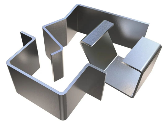
- Z-வளைவு படிநிலை உயரம் — ஆஃப்செட் வளைவுகளுக்கு, பொருளின் தடிமன் மற்றும் டை ஸ்லாட் அகலத்தை அடிப்படையாகக் கொண்டு குறைந்தபட்ச செங்குத்து படிநிலை உயரங்கள் தேவைப்படுகின்றன. தரநிலை விருப்பங்கள் 0.030 அங்குலம் முதல் 0.312 அங்குலம் வரை உள்ளன.
- கவுண்டர்சிங்க் வைப்பிடம் — வளைவுகள் மற்றும் ஓரங்களிலிருந்து விலகி கவுண்டர்சிங்க்குகளை வைக்கவும், சிதைவைத் தடுக்க. முக்கிய விட்டங்கள் 0.090 அங்குலம் முதல் 0.500 அங்குலம் வரை இருக்க வேண்டும்; தரநிலை கோணங்கள் (82°, 90°, 100° அல்லது 120°) பயன்படுத்தப்பட வேண்டும்.
பல வளைவுகளைக் கொண்ட சிக்கலான பாகங்களுக்கு வளைவு வரிசை திட்டமிடுதல் மிகவும் முக்கியமானது. பல தொடர் செயல்பாடுகள் மூலம் உலோகங்களை வடிவமைத்தல் கவனமான வரிசையை தேவைப்படுத்துகிறது — ஒவ்வொரு வளைவும் அடுத்தடுத்த கருவிகள் பொருத்துதலுக்கு தேவையான இடைவெளியை விட்டுச் செல்ல வேண்டும். பொதுவாக, வெளிப்புற வளைவுகளுக்கு முன் உள் வளைவுகளைச் செய்யவும்; சாத்தியமான அனைத்து நேரங்களிலும் பாகத்தின் மையத்திலிருந்து வெளிப்புறமாக வேலை செய்யத் தொடங்கவும்.
உங்கள் வளைத்தல் திட்டங்களை மேம்படுத்துதல்
தயாரிப்புக்காக வடிவமைப்புகளைச் சமர்ப்பிப்பதற்கு முன், இந்த அமைப்பு முறையான சரிபார்ப்புப் பட்டியலை முழுமையாக முடிக்கவும். ஒவ்வொரு பொருளும் தாமதங்களையும், மீண்டும் வேலை செய்ய வேண்டிய நிலைமைகளையும், தவறான பாகங்களையும் ஏற்படுத்தக்கூடிய சாத்தியமான பிரச்சனைகளை கவனிக்கிறது:
- பொருள் தேர்வை சரிபார்க்கவும் — உங்களால் தேர்ந்தெடுக்கப்பட்ட உலோகக் கலவை மற்றும் விறைப்பு நிலை உங்களால் குறிப்பிடப்பட்ட வளைவு ஆரங்களை ஆதரிக்கின்றனவா என்பதை உறுதிப்படுத்தவும். உங்கள் வடிவமைப்புடன் குறைந்தபட்ச ஆர பரிந்துரைகளைச் சரிபார்க்கவும். முக்கிய வளைவுகளுக்கு தானிய திசை அமைப்பை கவனிக்கவும்.
- வளைவு ஆர தரநிர்ணயங்களை சரிபார்க்கவும் — அனைத்து ஆரங்களும் பொருளின் குறைந்தபட்ச மதிப்புகளை பூர்த்தி செய்கின்றனவா அல்லது அதை மிஞ்சுகின்றனவா என்பதை உறுதிப்படுத்தவும். சாத்தியமான அளவில் பாகத்தின் முழு நீளத்திலும் ஒரே ஆரத்தைப் பயன்படுத்தவும். தரநிர்ணயம் செய்யப்பட்ட ஆரங்கள் தர வடிவமைப்பு கருவிகளுக்கு ஏற்றவையாக இருக்க வேண்டும் (0.030", 0.060", 0.090", 0.120" ஆகியவை பொதுவாக 3-நாள் விருப்பங்களாகும்).
- ஃபிளேஞ்ச் நீளங்களைச் சரிபார்க்கவும் — ஒவ்வொரு ஃபிளேஞ்சும் குறைந்தபட்சம் பொருள் தடிமனின் 4 மடங்கு நீளம் கொண்டிருக்கிறதா என்பதை உறுதிப்படுத்தவும். உங்கள் பொருள் தடிமன் மற்றும் வளைவு கோணத்திற்கு ஏற்ற பொருள்-குறிப்பிட்ட அட்டவணைகளில் குறைந்தபட்ச கால் நீளங்களைச் சரிபார்க்கவும்.
- துளைகள் மற்றும் அம்சங்களின் இடம் குறித்து மீண்டும் ஆய்வு செய்யவும் — அனைத்து துளைகள், ஸ்லாட்கள் மற்றும் அம்சங்களையும் வளைவு வரிகளிலிருந்து குறைந்தபட்சம் 2× தடிமன் கூடுதலாக வளைவு ஆரம் அளவு தூரத்தில் அமைக்கவும். அம்சங்கள் வளைவு முடிவுகளை நெருங்கும் இடங்களில் வளைவு விடுபடுத்தும் அறுவடைகளைச் சேர்க்கவும்.
- முக்கியமான அம்சங்களுக்கான தாங்குதல் தேவைகளை குறிப்பிடுங்கள் — தரநிலை வளைவு கோண துல்லியம் ±1 பாகை. குறைந்த துல்லியத்தை விரும்பினால், அதற்கு கீழே அழுத்துதல் (bottoming) அல்லது நாணயமாக்குதல் (coining) போன்ற முறைகள் தேவைப்படும், அதனால் செலவு அதிகரிக்கும். ஆஃப்செட் உயரத்தின் துல்லியம் பொதுவாக ±0.012 அங்குலம் வரை பராமரிக்கப்படும்.
- உற்பத்தி அளவைக் கவனிக்கவும் — குறைந்த அளவு உற்பத்திக்கு தரநிலை கருவிகள் மற்றும் காற்று வளைத்தல் (air bending) நெகிழ்வுத்தன்மை ஏற்றவை. அதிக அளவு உற்பத்திக்கு குறைந்த துல்லிய வரம்புகள் மற்றும் சுழற்சி நேரத்தைக் குறைக்க குறிப்பிட்ட கருவிகளில் முதலீடு செய்வது நியாயப்படும்.
- வளைவு வரிசையைத் திட்டமிடவும் — ஒவ்வொரு வளைவும் அடுத்தடுத்த வடிவமைப்புக்கு தேவையான இடைவெளியை விட்டுச் செல்லுமாறு செயல்பாடுகளின் வரிசையை வரைபடமாக்கவும். உற்பத்திக்கு முன்பாக சாத்தியமான கருவிகளின் இடையூறுகளை அடையாளம் காணவும்.
- ஸ்பிரிங்பேக்கை கணக்கில் கொள்ளுங்கள் — இறுதி கோணங்களை மட்டுமே குறிப்பிடவும், வளைத்த கோணங்களை அல்ல. உங்கள் தயாரிப்பாளர் பொருள் மற்றும் முறையை அடிப்படையாகக் கொண்டு ஏற்ற ஈடுசெய்தலை வழங்குவார் என நம்பவும்.
வளைத்தல் சரியான தேர்வு அல்ல என்பதை அறிந்து கொள்ளுங்கள்
இங்கே போட்டியாளர்கள் அரிதாகவே குறிப்பிடும் ஒன்று: வளைத்தல் எப்போதும் தீர்வாக இருக்காது. மற்ற வடிவமைப்பு செயல்முறைகள் சிறந்த முடிவுகளை வழங்கும் போது அதனை அங்கீகரிப்பது, நேரத்தையும் பணத்தையும் சேமித்து, பாகங்களின் தரத்தை மேம்படுத்தும்.
வர்த்தி ஹார்ட்வேர் நிறுவனத்தின் உற்பத்தி பகுப்பாய்வின்படி, தகுந்த அல்லாத தட்டு உலோக வடிவமைப்பு செயல்முறையைத் தேர்வு செய்வது வரவு-செலவு மீறலுக்கும், திட்ட தாமதங்களுக்கும் வழிவகுக்கும். உங்கள் வடிவமைப்பு பின்வரும் பண்புகளைக் கொண்டிருக்கும்போது மாற்று வழிகளைக் கருதவும்:
- மிகவும் குறுகிய வளைவு ஆரங்கள் — தேவையான வளைவு ஆரங்கள் பொருளின் குறைந்தபட்ச ஆரத்திற்குக் கீழே விழும்போது, ஆழமான இழுத்தல் (deep drawing) அல்லது நீர் வடிவமைப்பு (hydroforming) போன்ற செயல்முறைகள் வளைத்தலால் அடைய முடியாத வடிவங்களை உருவாக்க முடியும்.
- சிக்கலான 3டி வடிவங்கள் — கூட்டு வளைவுகள், அசமச்சமச்சமான வடிவங்கள் மற்றும் ஆழமான இழுத்தல் மூலம் உருவாக்கப்பட்ட வடிவங்கள் பெரும்பாலும் நீர் வடிவமைப்புக்கு ஏற்றவை. திரவ அழுத்தம் பஞ்ச்-டை வடிவமைப்பு மூலம் அடைய முடியாத வடிவங்களை உருவாக்க உதவுகிறது.
- மிக அதிக அளவுகள் — 50,000 பாகங்களுக்கு மேற்பட்ட அளவுகளில், முன்னேறும் டை ஸ்டாம்பிங் (progressive die stamping) உயர் கருவிகள் முதலீட்டை நிரப்பினாலும், ஒவ்வொரு பாகத்தின் விலையை குறிப்பிடத்தக்க அளவில் குறைக்கிறது.
- ஒருபோல் சுவர் தடிமன் தேவைகள் — தொடர் வளைத்தல் செயல்பாடுகளை விட சிக்கலான வடிவங்களில் ஹைட்ரோஃபார்மிங் மூலம் பொருளின் தடிமனை மிகவும் ஒழுங்கான முறையில் பராமரிக்க முடியும்.
- பாகங்களை ஒன்றிணைக்கும் வாய்ப்புகள் — பல வளைந்த பாகங்களை ஒரே ஹைட்ரோஃபார்ம்ட் பாகமாக மாற்ற முடியுமானால், அந்த வேறுபட்ட செயல்முறைக்கான சேமிப்பு கூடுதல் கூடுதல் சேகரிப்புச் செலவுகளை நியாயப்படுத்தலாம்.
தகடு உலோக வடிவமைப்பு செயல்முறையைத் தேர்வு செய்வது இறுதியில் சிக்கலான அமைப்பு, அளவு மற்றும் செலவு இலக்குகளைப் பொறுத்தது. எளிய வடிவமைப்புகளுடன் முன்மாதிரிகள் மற்றும் குறைந்த-மத்திய அளவு உற்பத்திக்கு வளைத்தல் சிறப்பாக செயல்படுகிறது. அதிக அளவு உற்பத்திக்கு ஸ்டாம்பிங் முன்னணியில் உள்ளது. ஹைட்ரோஃபார்மிங் சிக்கலான ஒற்றை-பாக வடிவங்களைக் கையாளுகிறது, அவை வேறுபட்ட வளைத்தல் மற்றும் கூட்டுதல் செயல்பாடுகளை தவிர்க்க முடியாதவையாக இருக்கும்.
உற்பத்தி வெற்றிக்காக கூட்டாண்மை
கூடுதலாக, வடிவமைப்பு கட்டத்தின் போது தயாரிப்பாளர்களுடன் ஒத்துழைப்பு கொள்வது அனுபவம் வாய்ந்த வடிவமைப்பாளர்களுக்கும் பயனுள்ளதாக இருக்கும். உற்பத்தியின் போது செலவு அதிகமான கண்டுபிடிப்புகளைத் தவிர்க்க உலோக வடிவமைப்பு மற்றும் வளைத்தல் நிபுணத்துவத்தை ஆரம்ப கட்டத்திலேயே பயன்படுத்த வேண்டும்.
தயாரிப்புக்கு ஏற்ற வடிவமைப்பு (DFM) ஆதரவை வழங்கும் தயாரிப்பு பங்குதாரர்களைத் தேடுங்கள். இந்த மதிப்பீடுகள் கருவிகளை வெட்டுவதற்கு முன்பாகவே சாத்தியமான வடிவமைப்பு செயல்முறைகள் தொடர்பான சிக்கல்களை அடையாளம் கண்டுபிடிக்கின்றன—செயல்பாட்டை பாதிக்காமல் உற்பத்தித் திறனை மேம்படுத்துவதற்காக வளைவு ஆரங்களில் சரிசெய்தல், அம்சங்களை மாற்றி அமைத்தல் அல்லது பொருளின் மாற்றங்களை பரிந்துரைக்கின்றன.
சாத்தியமான தயாரிப்பு பங்குதாரர்களிடம் கேட்க வேண்டிய முக்கிய கேள்விகள்:
- அவர்கள் சமர்ப்பிக்கப்பட்ட வடிவமைப்புகள் குறித்து DFM கருத்துகளை வழங்குகிறார்களா?
- அவர்களின் மதிப்பீட்டு நேரம் எவ்வளவு? (12-24 மணி நேரம் என்பது தீவிரமான திறனைக் குறிக்கிறது)
- உற்பத்தி கருவிகளுக்கு அடித்தளம் இடுவதற்கு முன்பாகவே அவர்களால் விரைவாக முன்மாதிரியை (புரோட்டோடைப்) தயாரிக்க முடியுமா?
- அவர்கள் எந்த தர சான்றிதழ்களைப் பெற்றுள்ளனர்? (ஆட்டோமொபைல் பயன்பாடுகளுக்காக IATF 16949)
- வளைத்தலுக்கு அப்பால் ஒருங்கிணைந்த உலோக வடிவமைப்பு தொழில்நுட்பங்களை—அடிக்கும் முறை (ஸ்டாம்பிங்), கூட்டுதல் (வெல்டிங்), கூட்டுதல் (அசெம்பிளி)—அவர்கள் வழங்குகிறார்களா?
சரியான வடிவமைப்பு செல்லுபடியாக்கத்தில் மேற்கொள்ளப்படும் முதலீடு, உற்பத்தி முழுவதும் லாபத்தை ஈட்டுகிறது. முதல் நாளிலிருந்தே சுலபமாக உற்பத்தி செய்யக்கூடிய பாகங்கள், பொறியியல் நேரத்தை வீணடிக்கும், திட்ட நேரத்தை தாமதப்படுத்தும் மற்றும் செலவுகளை அதிகரிக்கும் மீண்டும் மீண்டும் திருத்தும் செயல்முறைகளைத் தவிர்க்கின்றன. உங்கள் வளைவு அனுமதிப்பு கணக்கீடுகள், ஸ்பிரிங்பேக் ஈடுசெய்தல், மற்றும் குறைபாடுகளைத் தடுக்கும் முறைகள் அனைத்தும், அடிப்படை உற்பத்தி கட்டுப்பாடுகளை மதிக்கும் வகையில் வடிவமைக்கப்பட்டால் சிறப்பாக செயல்படும்.
நீங்கள் பிராக்கெட்கள், என்க்ளோசர்கள், சாஸிஸ் பாகங்கள் அல்லது கட்டிடக்கலை உறுப்புகளை உருவாக்குகிறீர்கள் எனில், இந்த வழிகாட்டுதல்கள் வளைத்தல் தொடர்பான அறிவை வெற்றிகரமான உற்பத்தி முடிவுகளாக மாற்றுகின்றன. பொருள் தேர்வுடன் தொடங்கவும், வடிவவியல் வரம்புகளை மதிக்கவும், உங்கள் வளைவு வரிசையை முன்கூட்டியே திட்டமிடவும், உலோகத்தை வெட்டுவதற்கு முன்பாக உற்பத்தி வல்லுநர்களுடன் வடிவமைப்புகளைச் செல்லுபடியாக்கவும். அதன் விளைவு? ஒவ்வொரு முறையும் குறிப்பிட்ட விதிமுறைகளுக்கு ஏற்ப சரியாக வளையும், தனிப்பயன் தரத்தை தொடர்ந்து பூர்த்தி செய்யும் மற்றும் திட்ட நேரத்திற்குள் வந்து சேரும் பாகங்கள்.
உலோக வடிவமைப்பில் வளைத்தல் தொடர்பான அடிக்கடி கேட்கப்படும் கேள்விகள்
1. உலோக வடிவமைப்பில் வளைத்தலின் வெவ்வேறு வகைகள் யாவை?
உலோக வடிவமைப்பில் மூன்று முக்கிய வளைத்தல் முறைகள் காற்று வளைத்தல் (air bending), அடிப்பகுதி வளைத்தல் (bottom bending) மற்றும் நாணய வளைத்தல் (coining) ஆகும். காற்று வளைத்தல் மிகவும் துல்லியமான முறையாகும்; இது மற்ற முறைகளை விட 50–60% குறைவான விசையை தேவைப்படுத்துகிறது, ஆனால் அதிக ஸ்பிரிங்பேக் (springback) ஐ உருவாக்குகிறது. அடிப்பகுதி வளைத்தல் உலோகத்தை V-வடிவ டை (V-die) உள் முழுமையாகத் தள்ளுகிறது, இதனால் கோண கட்டுப்பாடு சிறப்பாக இருக்கிறது மற்றும் ஸ்பிரிங்பேக் குறைகிறது. நாணய வளைத்தல் காற்று வளைத்தலை விட 3–5 மடங்கு அதிக விசையைச் செலுத்துகிறது, இதனால் ஸ்பிரிங்பேக் கிட்டத்தட்ட முற்றிலும் நீக்கப்படுகிறது; எனவே இது உயர் துல்லியம் தேவைப்படும் விண்வெளி பயன்பாடுகள் மற்றும் கடுமையான துல்லியத் தேவைகளைக் கொண்ட பயன்பாடுகளுக்கு ஏற்றது. இந்த ஒவ்வொரு முறையும் விசை தேவைகள், துல்லியத் தரம் மற்றும் கருவிகளின் தேய்வு ஆகியவற்றிற்கு இடையே தனித்தன்மை வாய்ந்த வரம்புகளை (trade-offs) வழங்குகிறது.
2. உலோக வடிவமைப்பில் வளைத்தல் செயல்முறை என்றால் என்ன?
வளைத்தல் என்பது சமதள தகடு உலோகத்தை கட்டுப்படுத்தப்பட்ட மாறுபாட்டின் மூலம் கோண அல்லது வளைந்த வடிவங்களாக மாற்றும் ஒரு தயாரிப்பு செயல்முறையாகும். கருவிகள் மூலம் பயன்படுத்தப்படும் விசை, பொருளின் யீல்ட் புள்ளியை மீறச் செய்து, நிரந்தரமான வடிவ மாற்றத்தை ஏற்படுத்தும் பிளாஸ்டிக் மாறுபாட்டை உருவாக்குகிறது. வளைத்தல் செயல்முறையின் போது, வெளிப்புற மேற்பரப்பு நீண்டு, உள்புற மேற்பரப்பு சுருங்குகிறது; வளைவின் மையத்தில் ஒரு நிருபாக அச்சு (neutral axis) செல்கிறது, அங்கு பொருள் நீண்டும் அல்லது சுருங்கியும் விளைவதில்லை. இந்த செயல்முறை வெட்டுதல் அல்லது காய்ச்சுதல் போன்றவற்றிலிருந்து மாறுபட்டு, பொருளின் பண்புகளை பாதுகாக்கிறது; எனவே அது வாகனம், விமானம் மற்றும் தொழில்துறை பயன்பாடுகளில் கட்டமைப்பு கூறுகளுக்கு மிகவும் முக்கியமானதாகும்.
3. தகடு உலோகத்திற்கான வளைவு அனுமதி (bend allowance) மற்றும் K-காரணி (K-factor) எவ்வாறு கணக்கிடப்படுகின்றன?
வளைவு அனுமதியை பின்வரும் சூத்திரத்தின் மூலம் கணக்கிடப்படுகிறதுஃ BA = (π/180) × A × (IR + K × T), இதில் A என்பது டிகிரிகளில் வளைவு கோணம், IR என்பது உள் ரேடியஸ், K என்பது K காரணி, மற்றும் T என்பது பொருள் தடிமன். K காரணி என்பது பொருள் உள்ள நடுநிலை அச்சின் இருப்பிடத்தை குறிக்கிறது, பொதுவாக வளைக்கும் முறை மற்றும் பொருள் வகையைப் பொறுத்து 0.3 முதல் 0.5 வரை இருக்கும். காற்று வளைவுக்காக, K- காரணி பொதுவாக 0.30-0.45 வரை இருக்கும்; கீழ் வளைவு 0.40-0.50 ஐப் பயன்படுத்துகிறது; நாணயமாக்கல் 0.45-0.50 ஐ அணுகுகிறது. துல்லியமான K- காரணி தேர்வு முடிக்கப்பட்ட பகுதிகளில் பரிமாண பிழைகளைத் தடுக்கிறது மற்றும் தட்டையான வடிவங்கள் வடிவமைக்கப்பட்ட பரிமாணங்களுக்கு சரியாக மொழிபெயர்க்கப்படுவதை உறுதி செய்கிறது.
4. உலோக வளைவில் பின்னடைவை ஏற்படுத்துவது எது? அதை எவ்வாறு ஈடுசெய்வது?
சுருள் திரும்புதல் (Springback) என்பது, வடிவமைப்பு அழுத்தம் நீக்கப்படும்போது மீள் வடிவ மாற்றம் சேமிக்கப்பட்ட ஆற்றலை விடுவிப்பதால் ஏற்படுகிறது; இது பொருள் தனது அசல் வடிவத்தை நோக்கி பகுதியளவு திரும்புவதை ஏற்படுத்துகிறது. ஸ்டெயின்லெஸ் ஸ்டீல் 10–15 டிகிரி வரை சுருள் திரும்பும், அதே நேரத்தில் மென்மையான இரும்பு (mild steel) பொதுவாக 2–4 டிகிரி வரை சுருள் திரும்பும். இதற்கான ஈடுசெய்யும் முறைகளில், மீள் மீளும் தன்மையை ஈடுகட்ட இலக்கு கோணத்தை விட அதிகமாக வளைத்தல் (overbending), மீள் மண்டலத்தைக் குறைக்க அடிப்பு (bottoming) அல்லது காய்ணிங் (coining) போன்ற முறைகளைப் பயன்படுத்துதல், மற்றும் கருவியின் வடிவவியலைச் சரிசெய்தல் ஆகியவை அடங்கும். சமீபத்திய CNC பிரெஸ் பிரேக்குகள் உண்மை நேர கோண அளவீடு மற்றும் தானியங்கி ஈடுசெய்யும் செயல்பாடுகளை வழங்குகின்றன, இதன் மூலம் ±0.1 டிகிரி உள்ளே கோண மீள்தன்மையை அடைய முடிகிறது.
5. பொதுவான வளைத்தல் குறைபாடுகள் யாவை மற்றும் அவற்றை எவ்வாறு தடுக்கலாம்?
பொதுவான வளைவு குறைபாடுகளில் பிளவுகள் (மிகச் சிறிய வளைவு ஆரங்கள், தவறான துகள் திசை அல்லது வேலை செய்யப்பட்ட விறைப்புற்ற பொருள் காரணமாக), சுருக்கங்கள் (தடுப்பு அழுத்தம் போதுமானதாக இல்லாமை அல்லது முத்திரை இடைவெளி மிகைப்படுத்தப்பட்டிருத்தல்) மற்றும் மேற்பரப்பு சேதம் (மாசுபட்ட கருவிகள் அல்லது தவறான திரவ பூச்சு காரணமாக) ஆகியவை அடங்கும். தடுப்பு நடவடிக்கைகளில், பொருளின் வகையை அடிப்படையாகக் கொண்டு போதுமான வளைவு ஆரங்களைக் குறிப்பிடுதல், துகள் திசைக்குச் செங்குத்தாக வெட்டப்பட்ட பகுதிகளை அமைத்தல், சரியான முத்திரை திறப்பு அகலத்தைப் பயன்படுத்துதல் (பொதுவாக பொருளின் தடிமனை விட 6-8 மடங்கு), மற்றும் சுத்தமான, நன்றாக எண்ணெயிடப்பட்ட கருவிகளை பராமரித்தல் ஆகியவை அடங்கும். மேலும், வளைவு விடுவிப்பு வெட்டுகளைச் சேர்த்தல் மற்றும் ஓரங்களிலிருந்து உருளைகளை அகற்றுதல் ஆகியவை வலிமை மையப்படுத்தல் மற்றும் பிளவு தொடங்குவதைத் தடுக்க உதவுகின்றன.