 Majhne serije, visoki standardi. Naša storitev hitrega prototipiranja omogoča hitrejšo in enostavnejšo validacijo —

Nedestruktivno testiranje kovanih delov: 8 osnovnih točk pojasnjenih
Razumevanje netrujnih preiskav kovanin
Zamislite, da naložite v točno izdelano kovano jekleno komponento, le da bi odkrili skrito napako, ki je ogrozila njeno celovitost. Stavi so visoke – ne glede na to, ali proizvajate podvozja za letala, vzmetne roke za avtomobilske odprave ali flanec za naftne platforme. Prav zato so netrujne preiskave kovanih delov postale nepogrešljive pri sodobnih postopkih pregleda proizvodnje in NDT protokolih.
Kaj torej natanko so netrujne preiskave? NDT pomeni metode pregleda, s katerimi se oceni celovitost komponente, ne da bi jo na kakršenkoli način spremenili ali poškodovali. Slišali boste tudi izraza NDE (netrujna ocena) ali NDI (netrujni pregled) – ti izrazi se v panogi uporabljajo zamenljivo. Lepota tega pristopa? ULMA Forged Solutions , za razliko od destruktivnega testiranja, kjer je mogoče pregledati le vzorce, NDT omogoča testiranje vsake posamezne izdelane enote, kar znatno poveča varnost in zanesljivost izdelka.
Zakaj kovanke zahtevajo specializirane metode preverjanja
Pri primerjavi litja in kovanja razlike v strukturi materiala pojasnjujejo, zakaj kovano jeklo zahteva edinstvene pristope k pregledu. Kovanje izboljša zrnatost in ustvarja smerne trdnostne lastnosti, ki jih litje preprosto ne more doseči. Postopki toplega in hladnega obdelovanja, vključeni v kovanje, zagotavljajo nadpovprečne mehanske lastnosti – boljšo duktilnost, odpornost proti udaru in zmogljivost pri utrujanju.
To pa ne pomeni, da so kovani deli brez napak. Čeprav primerjave litja in kovanja sistematično ugodijo kovanim delom glede konstrukcijske celovitosti, sam postopek kovanja lahko povzroči subtilne napake. Nepravilnosti v oblikovanju orodij, spremembe temperature ali neenakomernosti materiala lahko ustvarijo notranje praznine ali površinske nezveznosti, ki ogrožajo zmogljivost.
NDT ohranja celotno vrednost kovanin, hkrati pa zagotavlja kakovost – vsak preizkušen del se lahko še vedno uporablja, saj postopek pregleda povzroči ničelno škodo materialu ali njegovi funkcionalnosti.
Skriti napaki, ki ogrožata celovitost kovanja
Kaj naredi te napake tako nevarne? Pogosto so nevidne s prostim očesom. Podpovršinske vključene nečistoče, mikroskopske razpoke ali nepravilni vzorci zrnine ležijo skrite pod navidez popolnimi površinami. V aplikacijah, kjer je varnost ključna, lahko te skrite napake povzročijo katastrofalne okvare.
Upoštevajte industrije, ki so odvisne od brezhibnih komponent iz kovanega jekla:
- Letalska in vesoljska industrija: Podvozja, diski turbin in strukturni deli trupa letala, kjer odpoved ni možna
- Avtomobilizem: Kolenčaki, batnice in dele suspenzije, ki so izpostavljeni milijonom ciklov obremenitve
- Nafta in plin: Prirube in spojke, ki delujejo pri ekstremnih tlakih v korozivnih okoljih
- Proizvodnja energije: Vratila turbin in reaktorskih komponent, ki zahtevajo absolutno zanesljivost
Vsak od teh sektorjev se zanaša na stroge protokole za izdelovalni pregled in NDT, da preveri, ali kovanine izpolnjujejo natančne specifikacije. Kot Industrijski pregled in analiza opozarja, je NDT postalo »nezanemarljivo« na vseh področjih, saj neodkriti napaki lahko povzročijo nevarne okvare ali dragocene škode opreme.
Osnovno načelo je preprosto: kovanje ustvarja komponente z izjemnimi lastnostmi trdnosti, vendar odgovorno proizvodnjo zahteva preverjanje. Metode NDE (nehunične evaluacije) zagotavljajo to jamstvo, ne da bi žrtvovali noben izdelani kos – zaradi tega so nepogrešljive za vsako kovalnico, ki se osredotoča na kakovost.
Pogoste napake v kovankah in njihovi vzroki
Preden izberete pravo metodo pregleda, morate razumeti, kar iščete. Dejstvo je, da lahko tudi najbolj izpopolnjen postopek kovanja povzroči napake. Znanje o tem, od kod izvirajo te napake – in kako se pojavljajo – neposredno vpliva na to, katere NDT metode jih bodo zaznale.
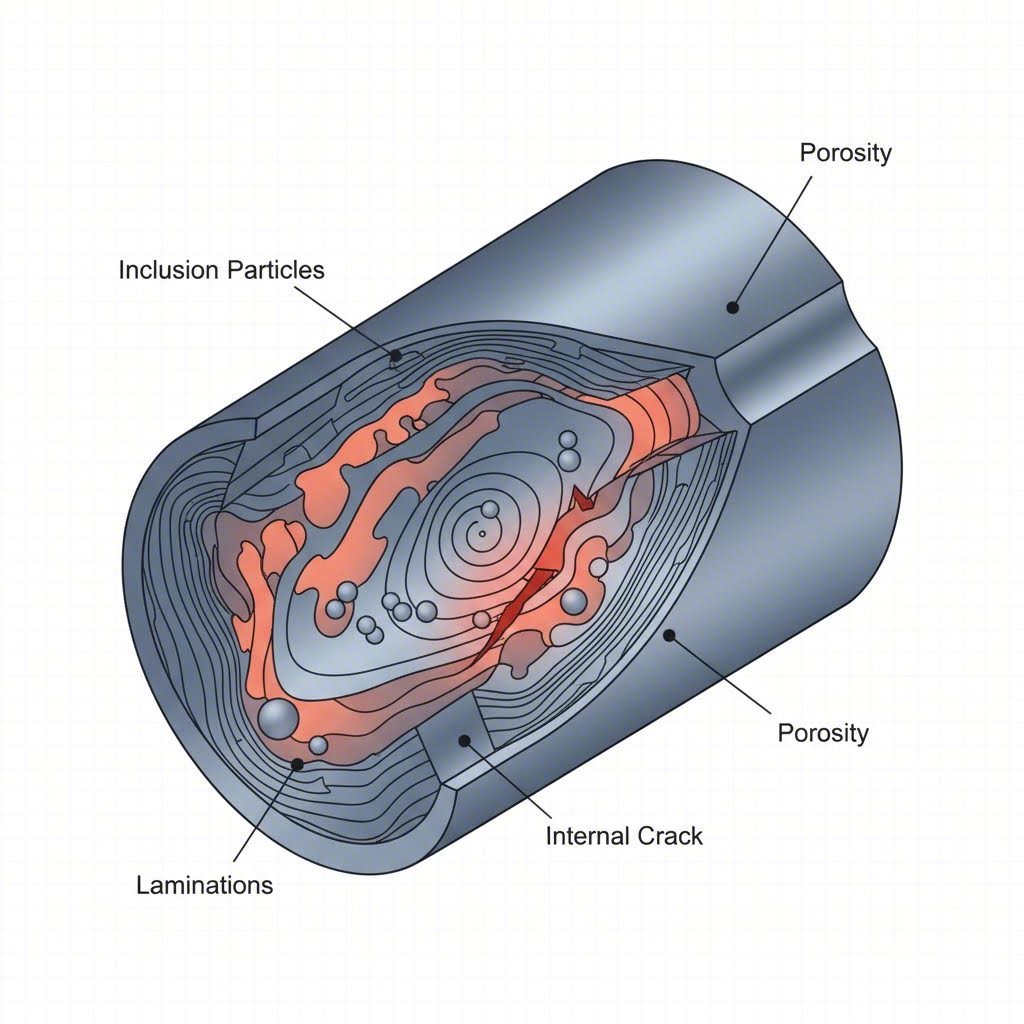
Napake pri kovanju si predstavljajte kot tri glavne kategorije glede na njihovo lokacijo in izvor. Vsaka vrsta zahteva različne strategije zaznavanja, in če spregledamo katerokoli od njih, bi to lahko pomenilo razliko med zanesljivim delom in dragovrnostno okvaro.
Notranje napake zaradi variabilnosti materiala in procesa
Notranje napake so še posebej nevarne, ker so popolnoma nevidne med vizualnim pregledom. Te napake se skrivajo pod površjem in čakajo, da povzročijo težave ob obratovalnem napetosti.
Poroznost in krčne votline nastanejo, ko se plini ujameta med vročim kovanjem ali ko material ne teče ustrezno, da bi izpolnil vse dele orodja. Ko delujete pri temperaturi kovanja jekla v območju od 1050°C do 1150°C, lahko že majhna odstopanja povzročijo nastanek ujetega zraka ali lokalizirano krčenje zaradi neenakomernega hlajenja kovine.
Vključki predstavljajo drugo resno težavo. Gre za tujke – oksidne delce, šlako ali drobce ognjevzdržnih materialov – ki se vdelajo v kovan del. Glede na Vodnik po kakovosti kovanja FCC-NA primešane nečistoče v kemični sestavi in neenakomernost surovin povzročajo vključke, ki oslabijo strukturno trdnost.
Ploščice so notranji lomi, povzročeni z embrittljenjem zaradi vodika – zlasti insidiozna napaka, saj se lahko pojavi šele dolgo po proizvodnji. Kot raziskave, objavljene v IRJET, pojasnjujejo slitnice z visoko vsebnostjo vodika v kombinaciji z neustreznimi hitrostmi hlajenja ustvarjajo te nevarne notranje razpoke, ki znatno zmanjšajo trdnost komponent.
Pri ocenjevanju razlike med litjem in kovanjem se vzorci notranjih napak znatno razlikujejo. Liti in kovani sestavni deli kažejo različne značilnosti napak – pri litih prevladuje poroznost zaradi strjevanja, medtem ko se pri kovanih napake pojavljajo zaradi pretoka materiala in težav pri termični obdelavi.
Površinske in strukturne napake pri kovankih
Površinske napake so pogosto lažje zaznavne, vendar ne manj pomembne. Nastajajo običajno zaradi interakcije orodja, težav pri nadzoru temperature ali pri rokovanju z materialom.
Prekrivanja in hladni zvarji nastanejo, kadar se med oblikovanjem kovina prekriva sama na sebi. Pri kovanju v zaprtih kalibrih prenapolnitev kalibrskih votlin ali napačna poravnava kalibrov povzroči, da se odvečni material prepogne nazaj in ustvari prekrivajoče se plasti, ki se ne zvarijo pravilno. Hladni zatiši posebej nastanejo, kadar temperatura kovanja pade prenizko, kar preprečuje primerno zlepljanje kovine tam, kjer se površine srečajo.
Površinske razpoke nastanejo zaradi več razlogov – pregrevanje billete, neustrezne hitrosti hlajenja ali obdelave materiala pod njegovo temperaturo rekristalizacije. Te razpoke se lahko pojavijo kot fine črte, vidne s prostim očesom, ali pa za njihovo zaznavanje zahtevajo magnetno prahovo ali penetrantsko preiskavo.
Lupine iz oksidov nastanejo, ko se oksidni odlag (lupine) med kovanjem stisne v površino. Dolgotrajno segrevanje v peči ali neustrezno odstranjevanje oksidov pred oblikovanjem vgradi te okside in pusti majhne jamice ali hrapave točke, ki ogrozijo celovitost površine.
Strukturne napake vplivajo na splošne lastnosti materiala, namesto da bi ustvarjale ločene napake:
- Neustrezna smer vlaken: Smerna trdnostna prednost kovanja je odvisna od poravnane strukture zrn – slabo oblikovanje orodja moti ta tokovni vzorec
- Ločevanje: Neenakomerna porazdelitev legirnih elementov ustvarja lokalizirane šibke točke
- Neopolna penetracija kovanja: Uporaba lahkotnih, hitrih udarcev le deformira površino, notranjost pa ostane z nerazvitimi dendritnimi strukturami
Razumevanje vzorcev napak pri litju in kovanju pomaga ekipam za kakovost pri določanju prednosti pri metodah pregleda. Spodnja tabela ponuja celovito klasifikacijsko matriko za načrtovanje pristopa k netruščnim preizkusom:
| Vrsta napake | Tipična vzročnost | Lokacija | Stopnja kritičnosti |
|---|---|---|---|
| Poroznost | Zaprte plinaste nečistoče, nepravilni tok kovine | Notranji | Visok |
| Strjalne votline | Neenakomerno hlajenje, premajhna količina materiala | Notranje/podpovršinske | Visok |
| Vključki | Oprabljen surovinski material, zadrževanje šlak | Notranji | Visok |
| Ploščice | Embrittlement zaradi vodika, hitro hlajenje | Notranji | Kritični |
| Laps | Preobremenitev orodja, prekomeren tok kovine | Površinske/podpovršinske | Srednji-Visok |
| Hladnih spojev | Nizka temperatura kovanja, slabo oblikovanje orodja | Površina | Srednji-Visok |
| Površinske razpoke | Prekomerno segrevanje, neustrezno hlajenje, nizka delovna temperatura | Površina | Visok |
| Lupine iz oksidov | Nezadostno odstranjevanje oksidov, predolgo izpostavljanje v peči | Površina | Nizka–srednja |
| Premik orodja | Neusklajena zgornja in spodnja orodja | Dimenzionalna | SREDNJE |
| Neprimeren prodor | Šibki udarci kladiva, nezadostna sila za kovanje | Notranja struktura | Visok |
Opazite, kako visoke temperature kovanja neposredno vplivajo na nastanek napak. Delo nad točko rekristalizacije omogoča ustrezno pretakanje in zlepek materiala, medtem ko padec temperature povzroči hladne zatike in razpoke na površini. Nasprotno pa prekomerno segrevanje povzroči rast zrn in težave z oksidacijo.
Ko sedaj razumete, katere napake se lahko pojavijo in od kje izvirajo, je naslednji korak povezava teh vrst napak z metodami pregleda, ki so najprimernejše za njihovo zaznavanje – z ultrazvočnim testiranjem, osnovno metodo za odkrivanje skritih notranjih nezveznosti.
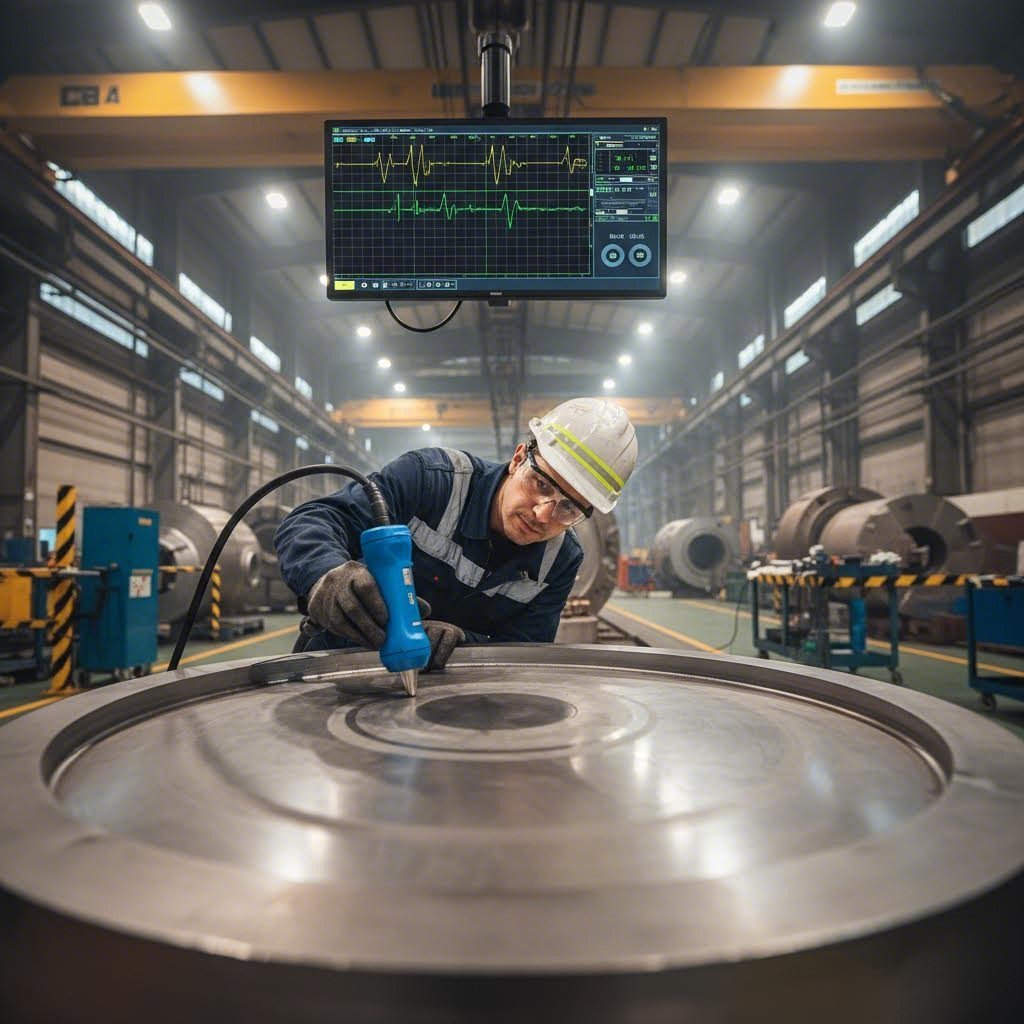
Metode ultrazvočnega testiranja in tehnični parametri
Ko gre za odkrivanje skritih notranjih napak, o katerih smo prej govorili, ultrazvočno testiranje predstavlja osnovno metodo pri kontroli kovanin. Zakaj? Ker zvočni valovi lahko prodrejo globoko v kovino in razkrijejo poroznost, vključke ter luske, ki jih nobena površinska metoda pregleda ne more najti.
Tako deluje: oddajnik pošlje visokofrekvenčne zvočne valove v kovano del. Ko ti valovi naletijo na nezveznost – praznino, razpok, ali vključek – se odbijejo nazaj. Naprava izmeri čas in amplitudo teh odbojev in natančno določi, kje se napake skrivajo ter kako pomembne so.
Po Tehnični priročnik ameriškega vojnega letalstva o ultrazvočnem pregledu , ultrazvok omogoča odkrivanje notranjih in zunanjih nezveznosti, od velikih ločitev do najmanjših napak, hkrati pa tudi merjenje celotne debeline materiala in globine posameznih napak.
Izbira ultrazvočnega sonde za različne geometrije kovanin
Izbira prave frekvence sonde ni ugibanje – gre za premišljeno odločitev, ki temelji na značilnostih vašega kovanca. Temeljno načelo? Višje frekvence zaznajo manjše napake, vendar slabše prodrejo, medtem ko nizke frekvence dobro prodrejo skozi debele dele, a spustijo majhne nezveznosti.
Pri pregledu večine kovanih fitingov in kovanja s prostim orodjem frekvence med 1 in 5 MHz dajo najboljše rezultate:
- 1 MHz: Najbolj primerno za debele prereze, materiale z grobim zrnom ter avstenitne nerjaveče jekle, kjer je dušenje visoko
- 2,25 MHz: Standardna pogonska frekvenca za splošni pregled jeklenih kovancev – uravnoteži prodirnost in občutljivost
- 5 MHz: Idealno za tanjše prereze, ki zahtevajo višjo ločljivost in zaznavanje manjših nezveznosti
- 10 MHz: Namensko za specializirane aplikacije, ki zahtevajo maksimalno občutljivost pri materialih z drobnim zrnom
Tu je praktično pravilo: napake morajo imeti vsaj eno dimenzijo enako ali večjo od polovice valovne dolžine, da jih je mogoče zanesljivo zaznati. Pri 2,25 MHz pri pregledovanju aluminija je najmanjša zaznana velikost napake približno 0,055 palca. Povečajte to na 5 MHz in lahko zaznate napake do velikosti 0,025 palca.
Postopek kovaškega kovanja ustvarja sestavne dele z različnimi debelinami in geometrijami, kar zahteva previden izbor sonde. Za velike gredne izdelke bi bilo morda potrebno uporabiti sonde z 1 MHz za doseganje popolnega prodora, medtem ko imajo natančni kovanje legirane jeklene zlitine s tesnejšimi tolerance koristi od pregledovanja z višjo frekvenco.
Kontaktna in neposredna metoda
Dve glavni metodi spajanja povezujeta vaš pretvornik s kovanskim delom:
Kontaktno testiranje postavi pretvornik neposredno na površino dela s plastjo skupne tekočine (običajno olje, glicerina ali komercialni gelski pripravki), ki odstranijo zračne reže. Ta pristop dobro deluje za:
- Preglede na terenu in prenosne aplikacije
- Velike kovine, ki se ne morejo ujeti v potopnih rezervoarjih
- Hitri postopki presejanja
Testiranje s potopom potopi pretvornik in kovino v vodo, kar zagotavlja dosledno sklopitev in omogoča avtomatizirano skeniranje. Prednosti vključujejo:
- Odlična doslednost sklopi
- Možnost uporabe fokusiranih pretvornikov za izboljšano občutljivost
- Lažje C-skeniranje za preslikavo lokacij napak
The Standard ASTM A388 določa, da morajo sklopila imeti dobre močilne lastnosti – SAE št. 20 ali 30 motorno olje, glicerin, borovico ali voda so sprejemljive možnosti. Ključno je, da se za umerjanje in pregled uporabi isto sklopilo, da se zagotovijo dosledni rezultati.
Neposredni žarek proti kotnemu žarku – aplikacije
Vaša usmerjenost napake določa, kateri kot žarka potrebujete:
Raven žarek (longitudinalni val) pregled pošilja zvok pravokotno na površino vstopa. Ta tehnika odlično ujema zaznavanje:
- Plasti, vzporedne s površino
- Poroznost in krčne votline
- Vključki, usmerjeni vodoravno
- Splošne prostorske napake
Kotni žarek (strižni val) pregled vpelje zvok pod kotom, navadno med 30° in 70°. Po standardu ASTM A388 je ta tehnika obvezna za votle kovinske izdelke z razmerjem zunanjega in notranjega premera manjšim od 2,0:1 ter osno dolžino večjo od 2 palcev. Preizkušanje s kotnim žarkom zazna:
- Prasko, usmerjene pravokotno na površino
- Obvodne in aksialne nezveznosti pri valjastih delih
- Napake v bližini robov in kotov
Tolmačenje ultrazvočnih rezultatov pri materialih z usmerjeno strukturo
Kovanke predstavljajo edinstvene izzive pri tolmačenju. Za razliko od litin z naključno zrnavo strukturo imajo kovanci smerne tokove zrna, ki vplivajo na širjenje zvočnega signala. Temperatura pri kovanju jekla med obdelavo vpliva na končno velikost zrn – grobere zrne pa odbijajo ultrazvočno energijo, kar zmanjšuje občutljivost in ustvarja ozadnje hrupnost.
Pri tolmačenju rezultatov bodite pozorni na naslednje ključne indikatorje:
- Amplituda eha zadnje stene: Močan in stabilen signal eha zadnje stene potrjuje dobro sklopitev in prediranje. Izguba signala nad 50 % lahko kaže na notranje nezveznosti ali težave s sklopitvijo
- Razmerje signal/pogoj: Grobnozrni materiali proizvajajo »hrup« ali ozadnje šume. Če se šum približuje mejni vrednosti zaznavanja, razmislite o zmanjšanju frekvence
- Večkratni odboji: Signali, ki se pojavljajo v rednih intervalih, pogosto kažejo na laminarne napake ali tesno razporejene nezveznosti
Trdota jekla vpliva tudi na parametre pregleda. Kovane izdelke, ki so bili toplotno obdelani in imajo višjo trdoto, lahko kažejo različne akustične lastnosti kot žareno mehčani materiali, zato zahtevajo referenčne standarde, prilagojene dejanskemu stanju komponente.
Zahteve ASTM E2375 za preiskavo kovank
ASTM E2375 določa postopkovni okvir za ultrazvočni pregled izdelkov iz kovanja, vključno s kovankami. Med ključne zahteve spadajo:
- Kvalifikacije osebja v skladu s SNT-TC-1A ali enakovrednimi nacionalnimi standardi
- Umerjanje z uporabo referenčnih blokov s ploskimi dnom izvrtanimi luknjami ali DGS (razdalja-pašnina-velikost) lestvicami
- Prekrivanje skeniranja najmanj 15 % med posameznimi prehodi za zagotavljanje popolne pokritosti
- Največja ročna hitrost skeniranja 6 palcev na sekundo
- Ponovno umerjanje ob vsaki spremembi iskalnih glav, skupnih sredstev ali nastavitev instrumenta
ASTM A388 posebno obravnava težke jeklene kovance, pri katerih zahteva pregled po toplotni obdelavi za ugotavljanje mehanskih lastnosti, vendar pred končnimi obdelovalnimi operacijami. Ta časovni trenutek zagotavlja največjo pokritost pregleda, medtem ko geometrija kovanca še vedno omogoča popoln dostop.
Omejitve in praktične razmisleke
Ultrazvočno testiranje ni brez omejitev. Poznavanje teh omejitev preprečuje napačno zaupanje v rezultate:
Učinki slepe cone: Območje neposredno pod pretvornikom ni mogoče zanesljivo pregledati med kontaktnim testiranjem. Dvoelementni pretvorniki ali sondažni senzorji z zakasnitveno črto pomagajo zmanjšati to omejitev.
Površinska hrubost: Hrapave površine razpršijo zvočno energijo in ustvarijo neenakomernosti pri sklopu. V tehničnem priročniku je opaženo, da hrapavost površin ne bi smela presegati 250 mikropalcev za optimalne rezultate.
Geometrijske omejitve: Kompleksne oblike kovancev lahko ustvarijo slepe cone, kamor zvok ne more doseči, ali kjer se odboji zamešajo z znaki napak.
Slabljenje materiala: Nekateri materiali – zlasti avstenitne nerjaveče jekle in nikljeve zlitine – hitro dušijo ultrazvok, kar omejuje globino pregleda.
Zahtevi za pripravo površine za ultrazvočni pregled
Pred nanosom pretvornika zagotovi ustrezno pripravo površine, da se dosežejo zanesljivi rezultati:
- Odstranite ves rahel premaz, barvo, umaznijo in korozivne produkte
- Dosežite površinsko finost 250 mikdolž ali manj za kontaktni pregled
- Zagotovite enakomeren pogoj površine – pokoščena barva ali neenakomerni prevleki morajo biti odstranjeni
- Preverite, ali so površine brez olja, maščob ali onesnažil, ki bi lahko vplivala na sklopitev
- Za hrapave površine je krajevno brušenje morda dovoljeno ob soglasju inženirja
- Površinski pogoj referenčnega standarda prilagodite dejanskemu stanju kovanke
Kot Tehnični priročnik podjetja Sonatest poudarja, da preverjanje hrapavosti površine mora biti del vsakodnevnih postopkov preverjanja amplitude – celo majhni indikaciji do 10 % višine zaslona lahko zahtevata beleženje za poročanje stranki.
Čeprav ultrazvočno testiranje odlično odkriva notranje nezveznosti, za napake na površini pogosto zahtevajo dopolnilne metode pregleda. Magnetna defektoskopija in kapilarna defektoskopija pokrijeta to vrzel – omogočata občutljivo zaznavanje napak na površini in pod njo, ki jih ultrazvočni valovi morda spregledajo.
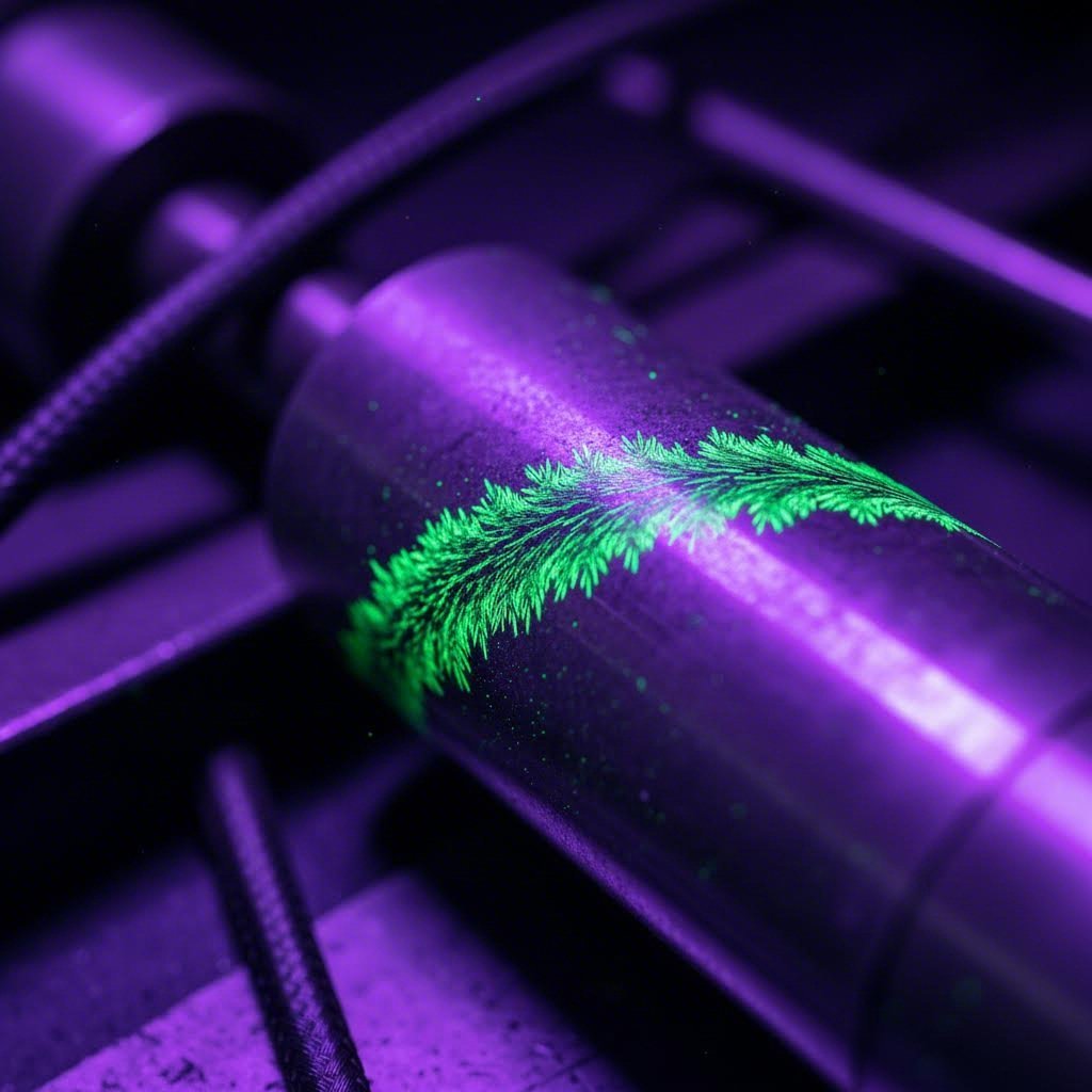
Pregled površin z magnetno in kapilarno defektoskopijo
Ultrazvočno testiranje odkrije skrite napake v notranjosti – a kaj je s površinskimi napakami? Praski, prekrivanja in razpoke, ki segajo do površine, pogosto uidejo zaznavanju z ultrazvokom, še posebej kadar so usmerjene vzporedno z zvočnim žarkom. Zato postanejo magnetna defektoskopija in kapilarna defektoskopija bistveni partnerici v vaši strategiji pregledovanja.
Te metode si predstavljajte kot svoje površinske detektive. Medtem ko UT posnema v notranjost materiala, se MT in PT specializirata na odkrivanje nezveznosti, ki segajo do površine – ravno tam, kjer napetostne koncentracije sprožijo utrujenostne okvare.
Magnetna tehnika za preverjanje železnih izkovkov
Magnetna tehnika deluje po enostavnem načelu: ko magnetizirate feromagnetni material, vsaka površinska ali podpovršinska nezveznost moti magnetno polje. Če na površino nanašete fine železove delce, se ti zberejo na mestih motenj – in tako ustvarijo vidne indikacije, ki preslikajo napake.
Pri uporabi za izdelavo iz nerjavnega jekla je pri tem naslednja težava: magnetna tehnika deluje le na feromagnetnih materialih. Martenzitski in feritni razredi nerjavnega jekla se dobro odzivajo na magnetno preverjanje, a avstenitni razredi, kot sta 304 in 316, ne delujejo – saj so nemagnetni. Pri izdelavi iz avstenitnih razredov nerjavnega jekla morate namesto tega uporabiti preizkus z vpenjanjem.
Metode magnetizacije in zahteve po jakosti polja
Doseganje ustrezne ravni magnetizacije določa občutljivost vašega pregleda. Glede na ASTM E1444 , ki služi kot vodilo za preiskavo z magnetnimi delci, se več tehnik magnetizacije uporablja za različne geometrije kovanja:
- Neposredna magnetizacija (glavni posnetek): Tok teče neposredno skozi del, kar ustvarja krožno magnetno polje. Učinkovito za odkrivanje vzdolžnih napak v valjastih kovancih
- Posredna magnetizacija (navitje): Del je postavljen znotraj navitja, ki prevaja tok, kar ustvari vzdolžno polje. Najboljše za iskanje prečnih razpok
- Magnetizacija z jokom: Prenosni elektromagneti ustvarjajo lokalizirana polja—idealno za terenske preglede velikih kovanih komponent iz nerjavnega jekla
- Proizvodi: Ročni elektrodi ustvarjajo krožna polja med kontakti za preverjanje na točkah
Jakost polja mora doseči 30–60 gauss na površini pregleda za zanesljivo zaznavanje. Če je premajhna, se delci ne bodo nabirali na nezveznostih. Če je prevelika, boste videli lažne indikacije zaradi hrapavih površin ali sprememb geometrije.
Mokra in suha metoda z delci
Izbira med mokrimi in suhimi delci je odvisna od vaših zahtev za zaznavo:
Mokra metoda vsebuje fluorescenčne ali vidne delce, razpršene v oljnem ali vodnem nosilcu. Ko obdelujete komponente iz nerjavnega jekla ali ogljikovega jekla, ki zahtevajo največjo občutljivost, mokri fluorescenčni delci pod UV-A svetlobo dajo najboljše rezultate. Delci se enostavno premaknejo v fine nezveznosti, fluorescenca pa ustvari visoko kontrastne indikacije.
Suh metod uporablja obarvan prah, ki se neposredno nanaša na namagneteno površino. Ta pristop deluje bolje za:
- Pregled vročih površin (do 600 °F)
- Hrapnje površine, kjer tekočina ne bi enakomerno razpršila
- Zaznavanje napak pod površino, kjer so potrebna globlje prodorna polja
ASTM E709 podaja smernice za tehnike magnetnega prahu in opisuje priporočene postopke za različne velikosti in oblike železnih delov. Ta dokument dopolnjuje ASTM E1444, da določi popolne postopke pregleda.
Uporaba prebitnega testiranja in upoštevanje časa zadrževanja
Ko vaš kovanec ni feromagneten – ali kadar potrebujete absolutno gotovost glede napak na površini – vam testiranje s tekočim prebitnim sredstvom ponuja rešitev. Ta metoda deluje na skoraj vsakem nepropornem materialu in je zato najpogosteje izbrana za kovane nerjaveče jekle avstenitnih razredov, aluminijaste kovance in titanove komponente.
Postopek sledi logični zaporedju: nanašanje prebitnega sredstva, dovoljenje časa zadrževanja, odstranitev odvečnega sredstva, nanašanje razvijalca in interpretacija indikacij. Vsak korak je pomemben, vendar pogosto čas zadrževanja določa uspeh ali neuspeh.
Smernice za čas zadrževanja prebitnega sredstva
Čas zadrževanja – obdobje, ko penetrant ostaja na površini pred odstranitvijo – se znatno razlikuje glede na material in pričakovano vrsto napake. Glede na ASTM E165/E165M preizkus s penetrantom zazna nezveznosti, odprte na površini, vključno s počesnimi, zatiči, preklopi, hladnimi zapirali, krčenjem in pomanjkanjem spojitve.
Splošne priporočitve za čas zadrževanja:
- 5–10 minut: Gladke obdelane površine, široke odprte napake, aluminijeve in magnezijeve zlitine
- 10–20 minut: Standardne odlitke iz ogljikovega in nizkolegiranega jekla, tipične utrujene razpoke
- 20–30 minut: Tesne razpoke, razpoke zaradi korozije pod napetostjo, komponente za uporabo pri visokih temperaturah
- več kot 30 minut: Zelo tesne neprekinjenosti, titanove in nikljeve zlitine, kritične aerospace aplikacije
Površinska obdelava jekla pred pregledom bistveno vpliva na zahtevan čas prebivanja. Kovanci, ki so bili obdelani s pikljanjem ali drugimi mehanskimi površinskimi obdelavami, lahko imajo stisnjene površinske plasti, ki upočasnijo prodor penetranta – kar zahteva podaljšane čase prebivanja.
Izbira sistema penetranta
ASTM E1417 in SAE AMS 2644 razvrščata sisteme penetrantov po stopnji občutljivosti (1–4) in metodi odstranjevanja (z vodo izpirni, z dodatkom emulgatorja, odstranljivi s topilom). Višje ravni občutljivosti omogočajo odkrivanje drobnih napak, vendar zahtevajo natančnejše postopke, da se izognemo prekomernemu izpiranju.
Za večino kovanca iz nerjavnega jekla ali ogljikovega jekla sistem Tip I (fluorescenčni), Metoda C (odstranljiv s topilom), pri stopnji občutljivosti 2 ali 3 ponuja odličen kompromis med zmogljivostjo odkrivanja in praktično uporabnostjo.
Vpliv toplotne obdelave po kovanju na časovni trenutek pregleda
Tu je pomembna težava, ki vpliva tako na MT kot na PT: kdaj morate opraviti pregled glede na toplotno obdelavo?
Odgovor je odvisen od tega, kaj poskušate najti:
Preglejte PRED toplotno obdelavo, kadar:
- Iščete napake pri kovanju, kot so prekrivanja, razpoke in hladni zapori, ki so nastali med procesom kovanja
- Preverjate kakovost materiala pred dražjo toplotno obdelavo
- Bo delu sledilo bistveno obdelovanje po toplotni obdelavi (odstranjevanje površin za pregled)
Preglejte PO toplotni obdelavi, kadar:
- Zaznate razpoke zaradi kaljenja, ki nastanejo zaradi hitrega hlajenja
- Najdete razpoke zaradi brušenja po toplotni obdelavi
- Opravljate končni sprejemni pregled
- Material doživi pomembne spremembe lastnosti (utrdnjene površine vplivajo na občutljivost MT)
Številne specifikacije zahtevajo pregled v obeh fazah – zgodnje odkrivanje napak, povezanih s procesom, ter preverjanje, da toplotna obdelava ni povzročila novih nezveznosti.
MT proti PT: Izbira pravilne površinske metode
Ko bi lahko obe metodi tehnično delovali, kako izbrati? Naslednja primerjava obravnava ključne dejavnike odločanja:
| Faktor | Magnetno delčno preverjanje (MT) | Preverjanje s tekočino (PT) |
|---|---|---|
| Ustreznost materialom | Samo feromagnetni (jeklo z ogljikom, martenzitna/ferritna nerjaveče jeklo) | Vsi nepropustni materiali (vsi kovini, keramika, plastične mase) |
| Odkrivanje napak | Površinske in nekoliko podpovršinske (do globine 0,25 palca) | Samo površinsko razpoke |
| Občutljivost na usmerjenost napak | Najbolj primeren za napake, pravokotne na magnetno polje | Enako občutljiv na vse orientacije |
| Zahtevki glede stanja površine | Srednje – deluje skozi tanke prevleke | Pomembneje – površina mora biti čista in brez onesnaženja |
| Relativna občutljivost | Zelo visoka za feromagnetne materiale | Visoka (odvisna od ravni občutljivosti penetranta) |
| Čas obdelave | Hitro – takojšnja prikaz napake | Počasneje – zahteva čas namakanja in razvijanja |
| Zaznavanje podpovršinskih napak | Da—zazna pomanjkljivosti blizu površine | Ne—prekinitev mora doseči površino |
| Prenosljivost | Dobro z opremo z jarmom | Odlično—potrebna je minimalna oprema |
Pri feromagnetnih kovaninah MT navadno zmaguje po hitrosti in sposobnosti zaznavanja podpovršinskih napak. Vendar ko delate s nemagnetnimi materiali ali potrebujete enakomerno občutljivost ne glede na usmerjenost napake, postane PT jasna izbira.
Oba postopka odlično ugotavljata površinske napake, ki jih pogosto ultrazvočni pregledi spregledajo. Vendar nekatere geometrije kovanin in vrste napak zahtevajo še specializiranejše pristope. Radiografsko in vrtinčno tokovno testiranje še dodatno razširita vaše možnosti zaznavanja – zlasti pri kompleksnih oblikah in hitrih pregledih.
Področja uporabe radiografskega in vrtinčnega tokovnega testiranja
Kaj se zgodi, ko ultrazvočni valovi ne morejo doseči vsakega kota vašega kovanca? Kompleksne geometrije, zapleteni notranji prehodi in tesni dostopni točki ustvarjajo slepe cone pri pregledu, ki jih konvencionalni UT preprosto ne more pokriti. Točno v takšnih primerih stopita v ospredje radiografsko testiranje in vrtinčno tokovno testiranje – zapolnita ključni vrzeli v zaznavanju, ki ju druge metode puščajo odprte.
Ti tehniki ponujata edinstvene prednosti, ki dopolnjujejo vaš obstoječi orodjarni za preglede. Radiografija omogoča stalno vizualno dokumentacijo notranje strukture, medtem ko vrtinčno tokovno testiranje zagotavlja hitro površinsko preverjanje brez potrebe po porabnih materialih, kot jih zahtevata MT ali PT.
Radiografski pregled za kompleksne geometrije kovancev
Radiografsko testiranje uporablja prodirajoče sevanje – X-žarke ali gama žarke – za ustvarjanje slik notranje strukture kovanca. Predstavljajte si to kot rentgenski posnetek za kovine: sevanje preide skozi del, razlike v gostoti ali debelini materiala pa se na nastali sliki prikažejo kot razlike v kontrastu.
ASTM E1030 določa standardno prakso za radiografsko preiskavo kovinskih litin, katere načela so enako uporabna tudi za kovanke s kompleksnimi notranjimi značilnostmi. Metoda se izredno dobro uporablja v primerih, ko ultrazvok naleti na omejitve:
- Zapleteni notranji votlinski prostori: Kovanke z obdelanimi vrtinami, prereznanimi kanali ali votlimi profili, kjer se zvočni valovi naključno sipajo
- Spremenljiva debelina stene: Komponente, pri katerih spremembe debeline ustvarjajo slepe cone za ultrazvočne žarke
- Geometrijska zapletenost: Intrikatni dizajni kovalnih kalibrov, ki ustvarjajo oblike, ki otežujejo dostop do senzorjev
- Trajna dokumentacija: Uporaba, ki zahteva arhivske posnetke za sledljivost
Kovalni kalibri, uporabljeni pri zaprtih postopkih kovanja, ustvarjajo vedno bolj kompleksne geometrije, ki izzivajo tradicionalne metode pregleda. Ko se tehnike kovanja razvijajo za izdelavo komponent skoraj končnih oblik, postaja radiografija še pomembnejša za preverjanje notranje kakovosti.
Fotografska plošča proti digitalni radiografiji
Tradicionalna filmska radiografija je industriji služila desetletja, vendar digitalna radiografija (DR) in računalniška radiografija (CR) sedaj ponujata pomembne prednosti:
- Takojšnja razpoložljivost slik: Brez zamude zaradi kemične obdelave – slike se pojavijo v sekundah
- Izboljšana obdelava slik: Digitalna prilagoditev kontrasta razkrije majhne napake, ki bi jih lahko film spregledal
- Zmanjšana izpostavljenost sevanju: Detektorji z višjo občutljivostjo zahtevajo nižje doze sevanja
- Enostavno shranjevanje in prenos: Digitalne datoteke se brezhibno vključijo v sisteme za upravljanje kakovosti
Za preverjanje orodij za kovanje in kontrolo kakovosti v proizvodnji digitalni sistemi bistveno pospešijo postopke pregleda, hkrati pa izboljšajo sposobnost karakterizacije napak.
Omejitve radiografije
Čeprav ima prednosti, radiografija kaže določene omejitve, ki jih morate razumeti:
- Zahtevi za varnost ob sevanju: Stroge kontrole izpostavljenosti, ekraniranja in certifikacije osebja dodajajo zapletenosti in stroške
- Usmerjenost ravninskih napak: Razpoke, poravnane vzporedno z žarkom sevanja, lahko ostanejo nevidne – pomembna je usmerjenost
- Omejitve debeline: Zelo debele predele potrebujemo močne vire in dolge čase izpostavljenosti
- Čas nastavljanja: Postavljanje vira, dela in detektorja zahteva previdno geometrijsko razporeditev
Hladno kovani sestavni deli z ožjimi tolerance in izpopolnjenimi površinami pogosto predstavljajo idealne kandidate za radiografsko preiskavo – gladke površine in natančne geometrije omogočajo optimalno kakovost slike.
Preizkušanje z vrtinčenimi tokovi za hitro površinsko preverjanje
Tukaj je metoda, ki se pogosto spregleda pri razpravah o pregledih kovanja: preizkušanje z vrtinčenimi tokovi. Kljub temu ECT ponuja izjemne zmogljivosti za zaznavanje napak na površini in pod površino v prevodnih materialih – brez porabnih materialov, posebne priprave površine ali stika s kosom.
Načelo je elegantno: izmenični tok, ki teče skozi tuljavo, ustvari elektromagnetno polje. Ko se ta tuljava približa prevodnemu materialu, inducira vrotaste tokove – vrtinčene tokove – v površinskih plasteh. Vsaka nezveznost moti te tokove in spreminja impedanco tuljave na merljiv način.
Prednosti ECT pri pregledu kovanj
Zakaj si mora preizkušanje z vrtinčenimi tokovi prislužiti mesto v vašem programu pregleda kovanj?
- Hitrost: Hitrosti skeniranja več čevljev na sekundo naredijo ECT idealnim za preverjanje pri visokem obsegu proizvodnje
- Brez porabnih materialov: Za razliko od PT in MT, ECT ne zahteva penetrantov, delcev ali nosilcev – kar zmanjša stalne stroške in vpliv na okolje
- Prijazno do automatizacije: Kolute se lahko enostavno vgradi v robotske sisteme za rokovanje, kar omogoča dosledno in ponovljivo preverjanje
- Toleranca stanja površine: Tanke oksidne plasti in manjše neravnine na površini ne ovirajo pregleda
- Zmožnost razvrščanja materialov: ECT lahko potrdi stanje toplotne obdelave, zazna mešane materiale in preveri sorte zlitin
Pri orodjih za kovanje, ki izpirajo ponavljajoče se toplotne obremenitve, ECT ponuja učinkovit način preverjanja celovitosti površine brez demontaže stiskalne opreme.
Omejitve ECT-ja in upoštevanje lažnih pozitivnih rezultatov
Eddy current testiranje ni brez izzivov. Poznavanje teh omejitev preprečuje napačno interpretacijo:
- Pojav skin-depth: Vrtinčene tokove se koncentrirajo blizu površine – za večjo prodornost so potrebne nižje frekvence, kar zmanjša občutljivost
- Občutljivost na razdaljo od površine: Spremembe razdalje med sondo in površino ustvarjajo signale, ki lahko zakrijejo ali posnemajo napake
- Robni efekti: Robovi delov in spremembe geometrije proizvedejo močne signale, ki zahtevajo previdno interpretacijo
- Spremenljivost materiala: Spremembe velikosti zrn, vzorci ostankov napetosti in lokalne razlike v trdosti vplivajo na odziv
Hladni kovanju izdelani komponenti z utrjenimi površinami lahko pri elektromagnetnem preiskovanju kažejo odzive zaradi gradienta utrjevanja samega – ne zaradi dejanskih napak. Ustrezen referenčni standard, prilagojen dejanskemu stanju materiala, pomaga ločiti resnične nezveznosti od lažnih pozitivnih rezultatov.
Nove tehnologije, ki napredujejo pri karakterizaciji napak
Področje nedestruktivnega preizkušanja se nadaljuje razvijati, pri čemer napredne tehnologije znatno izboljšujejo zmožnosti odkrivanja in karakterizacije napak:
Fazno nizko ultrazvočno testiranje (PAUT)
Tehnologija faziranega polja uporablja več ultrazvočnih elementov, ki jih je mogoče posamezno krmiliti glede na časovanje in amplitudo. To omogoča:
- Elektronsko usmerjanje žarka brez mehanskega premikanja sonda
- Fokusirane žarke na več razdaljah v enem samem skeniranju
- Sektorska skeniranja, ki omogočajo prečno slikanje, podobno medicinski ultrazvočni diagnostiki
- Hitrejši pregled z izboljšano natančnostjo določanja velikosti napak
Pri kompleksnih geometrijah izkovkov s pomočjo tehnike PAUT prilagodimo kote žarkov v realnem času in ohranjamo optimalne kote pregleda kljub konturam površine.
Time-of-Flight Diffraction (TOFD)
TOFD uporablja difraktirane signale iz konчик napak namesto odsevanih signalov s ploskev napak. Ta tehnika omogoča:
- Natančno merjenje globine razpok neodvisno od usmeritve napake
- Visoko verjetnost zaznavanja ravninskih napak
- Trajni trakovni zapisi za dokumentacijo
Računalniška tomografija (CT)
Industrijski CT ustvarja tridimenzionalne rekonstrukcije iz več projekcij rentgenskega sevanja. Čeprav omejujejo široko uporabo visoki stroški opreme, CT omogoča nepremagovljalno volumetrično karakterizacijo za kritične aplikacije kovanja – popolnoma natančno razkrije lokacijo, velikost in morfologijo napak.
Ko proizvajalci kovanj postopoma prehajajo na bolj kompleksne geometrije in tesnejše specifikacije, se naložbe v te napredne tehnologije vse pogosteje izplačujejo zaradi izboljšanega zaznavanja napak in zmanjšanega odstotka lažnih alarmov.
Ob tem razumevanju razpoložljivih tehnologij za pregledovanje se naslednje logično vprašanje nanaša na to, katero metodo je treba uporabiti za posamezno vrsto napake. Ustvarjanje sistematičnega pristopa k izbiri metode zagotavlja, da skozi mrežo vaše kontrole kakovosti nič ne uide.
Izbira prave NDT metode za določene vrste napak
Spoznali ste napake, ki ogrožajo kovane dele, in metode pregleda, s katerimi jih je mogoče odkriti. A tu je izziv, s katerim se soočajo mnoge ekipe za kakovost: kako izbrati pravo metodo za pravo napako? Napačna izbira pomeni prepuščene napake, zapravljen čas pregledovanja ali oboje.
Dejstvo je, da nobena sama neporušilna preskusna metoda ne zazna vsega. Vsaka metoda ima slepe cone – vrste napak, usmeritve ali lokacije, kjer se verjetnost zaznave znatno zmanjša. Učinkovit program pregledovanja pomeni razumevanje teh omejitev in ciljno kombiniranje metod.
Ustvarimo okvir odločanja, ki ga potrebujete za izbiro optimalnih metod zaznavanja za vsak scenarij napak, s katerim se boste srečali pri proizvodnji kovanih fitingov in pregledovanju jeklenih kovank iz litine.
Primerjanje vrst napak z optimalnimi metodami zaznavanja
Zamislite si odkrivanje napak kot ribolov z različnimi mrežami – vsaka mreža ulovi določene ribe, medtem ko druge plavajo naravnost skozi. Vaši metode pregleda delujejo na enak način. Ključ je v tem, da veste, katera »mreža« ulovi katero »rbo«.
Notranji volumnski napaki
Poroznost, krčne votline in vključki se skrivajo globoko znotraj kovanega ogljikovega jekla, kamor površinske metode ne morejo segniti. Vaša glavna orodja za zaznavanje so:
- Ultrazvočno testiranje: Metoda prve vrste za notranje diskontinuitete – visoka občutljivost za volumnske napake pri ustrezni usmeritvi
- Radiografsko testiranje: Odlična za zaznavanje sprememb gostote in nepravilno oblikovanih votlin; omogoča trajno vizualno dokumentacijo
Zakaj obe? UT odlično zaznava ploskovne diskontinuitete, ki so pravokotne na smer žarka, medtem ko RT zazna napake ne glede na njihovo usmerjenost. Pri kritičnih aplikacijah kovanja iz ogljikovega jekla kombinacija obeh metod zagotovi celovito notranjo pokritost.
Površinske razpoke
Razpoke, ki segajo do površine, zahtevajo različne strategije, odvisno od lastnosti materiala:
- Feromagnetni materiali: Preizkušanje z magnetnimi delci omogoča odlično občutljivost – delci se močno kopičijo na mestih razpok
- Nemagnetni materiali: Preizkušanje z vdirnimi tekočinami postane vaša glavna metoda, pri čemer se raven občutljivosti prilagodi pričakovani širini razpok
- Potreba po hitrem preverjanju: Vrtinčni tok omogoča hitro zaznavanje brez potrošnih materialov
Prekrivanja in zlepi
Te napake, značilne za kovanje, predstavljajo posebne izzive pri zaznavanju. Pri zaprtih kovankah se prekrivanja pogosto oblikujejo ob črtah presledka ali tam, kjer se material prepogne med polnjenjem kalupa. Usmerjenost napake določa najprimernejši pristop:
- Površinska prekrivanja: MT ali PT, odvisno od magnetnih lastnosti materiala
- Podpovršinska prekrivanja: UT z naklonskim žarkom in ustrezno usmeritvijo žarka
- Kompleksne geometrije prekrivanja: Kombinacija površinskih in volumnskih metod
Postopki kovanja z odprtim orodjem ustvarjajo različne vzorce prekrivanja—običajno povezane s sledmi manipulatorja ali neenakomerno redukcijo. Za zaznavanje teh napak je pogosto potrebna ultrazvočna preiskava pod več kot enim kotom, da se zagotovi odkrivanje ne glede na orientacijo.
Pretok zrn in strukturna vprašanja
Nepravilen pretok zrn ne povzroča ločenih motenj—predstavlja degradacijo lastnosti materiala na določenih območjih. Za zaznavanje so potrebni specializirani pristopi:
- Makro-prezentiranje: Razkrije vzorce pretoka zrn na prerezu vzorcev (destruktivno)
- Kartiranje ultrazvočne hitrosti: Spremembe hitrosti kažejo na spremembe usmerjenosti zrn
- Meritve prevodnosti z vrtinčnimi tokovi: Zaznava spremembe lastnosti, povezane s strukturo zrn
Matrika učinkovitosti metod za odkrivanje napak
Tukaj je celoviti vodnik za ujemanje, ki združuje vse zmožnosti zaznavanja. Uporabite to matriko pri razvoju načrtov pregleda za preverjanje kakovosti kovanja in litja:
| Vrsta napake | Ut | MT | PT | Rt | Ect | Opombe |
|---|---|---|---|---|---|---|
| Poroznost (notranja) | ★★★★☆ | N/A | N/A | ★★★★★ | N/A | RT prikazuje velikost/porazdelitev; UT zazna večje votline |
| Strjalne votline | ★★★★☆ | N/A | N/A | ★★★★☆ | N/A | Oba postopka sta učinkovita; UT omogoča informacije o globini |
| Vključki | ★★★★★ | N/A | N/A | ★★★☆☆ | N/A | UT je zelo občutljiv; RT lahko spregleda vključke nizke gostote |
| Površinske razpoke | ★★☆☆☆ | ★★★★★ | ★★★★★ | ★★☆☆☆ | ★★★★☆ | MT/PT primarni; ECT za hitro presejanje |
| Podpovršinske razpoke | ★★★★★ | ★★★☆☆ | N/A | ★★★☆☆ | ★★☆☆☆ | UT odličen; MT zazna le blizu površine |
| Napraski (površina) | ★★☆☆☆ | ★★★★★ | ★★★★☆ | ★★☆☆☆ | ★★★☆☆ | Tesni napraski morda zahtevajo PT z visoko občutljivostjo |
| Laps (podpovršinsko) | ★★★★☆ | ★★☆☆☆ | N/A | ★★☆☆☆ | ★☆☆☆☆ | UT z naklonskim žarkom in pravilno usmeritvijo je kritičnega pomena |
| Šve | ★★★☆☆ | ★★★★★ | ★★★★☆ | ★★☆☆☆ | ★★★★☆ | MT je najobčutljivejši za feromagnetne materiale |
| Težave s tokom zrn | ★★★☆☆ | N/A | N/A | N/A | ★★☆☆☆ | Zahtevane specializirane UT metode; makro-etch kot potrditvena metoda |
| Ploščice (H₂ razpoki) | ★★★★★ | N/A | N/A | ★★★☆☆ | N/A | UT je primarni način zaznavanja notranjih ploščic |
Ocenska lestvica: ★★★★★ = Odlična zaznavnost | ★★★★☆ = Dobro | ★★★☆☆ = Zadovoljivo | ★★☆☆☆ = Omejeno | ★☆☆☆☆ = Slabo | N/A = Ni uporabno
Gradnja večmetodne strategije pregleda
Zakaj enometodni pristopi propadejo? Razmislite o tem scenariju: pregledujete izdelke iz zlitine jekla samo z ultrazvočnim testiranjem. Vaš UT pregled ne odkrije nobenih notranjih nezveznosti – del izgleda zdrav. A vendar pa površinski lap, usmerjen vzporedno z vašim zvočnim žarkom, ostane popolnoma nezaznan. Ta lap postane mesto nastanka utrujenostne razpoke in komponenta odpove med obratovanjem.
Kompleksno zagotavljanje kakovosti zahteva večplastne strategije pregleda. Tukaj je, kako jih zgraditi:
Korak 1: Določite vrste kritičnih napak
Začnite s tem, da naštejete vse napake, ki bi lahko povzročile zavrnitev ali okvaro pri vaši specifični uporabi kovanega fitinga ali komponente. Upoštevajte:
- Katere napake so najverjetnejše glede na vaš postopek kovanja?
- Katere napake predstavljajo največje tveganje za delovanje v končni uporabi?
- Katerim zahtevam strank ali specifikacij morate ustrezati?
Korak 2: Določite primarne metode odkrivanja
S pomočjo zgornje matrike učinkovitosti dodelite vsaki kritični vrsti napake primarno metodo odkrivanja. Ta metoda mora ponujati najvišjo verjetnost odkrivanja za to specifično nezveznost.
Korak 3: Dodajte dopolnilne metode
Pri visoko pomembnih aplikacijah dodajte sekundarne metode, ki prekrivajo slepe točke primarnih metod. Klasični dopolnilni pari vključujejo:
- UT + MT: Notranje volumnetrično pokritje plus zaznavanje površinskih razpok pri feromagnetnih kovanih jeklih iz ogljika
- UT + PT: Enako dopolnilno pokritje za nemagnetne materiale
- RT + UT: Popolno notranje pokritje z orientacijsko neodvisnim zaznavanjem in informacijami o globini
- MT + ECT: Zaznavanje na površini z visoko občutljivostjo plus možnost hitrega presejanja
Korak 4: Določitev zaporedja pregleda
Vrstni red metod pregleda je pomemben. Za optimalne rezultate sledite temu splošnemu zaporedju:
- Vizualna pregledovanja: Vedno najprej—določi očitne površinske pogoje in težave s geometrijo
- Površinske metode (MT/PT): Izvedite pred UT, da določite površinske pogoje, ki bi lahko vplivali na sklopitev
- Prostorske metode (UT/RT): Celovita notranja preiskava po potrditvi površine
- Končni vizualni pregled: Preverite, ali so vsi znaki ustrezno dokumentirani in ovrednoteni
Po Primerjava metod NDT podjetja The Modal Shop , vsaka tehnika ponuja različne prednosti in omejitve—ultrazvočno testiranje omogoča visoko prodirnost in občutljivost za razpoke, medtem ko magnetna defektoskopija omogoča poceni, prenosno preiskavo z možnostjo zaznavanja podpovršinskih napak.
Primer praktične uporabe
Predstavljajte si, da razvijate načrt pregleda za izkovani povezovalni drog iz jekla z dodatki, ki je namenjen uporabi v visoko zmogljivih avtomobilih. Vaš večmetodni pristop bi lahko izgledal takole:
- 100 % vizualni pregled: Preverjanje očitnih površinskih stanj in ustreznosti dimenzij
- 100 % magnetno delčno preizkušanje: Mokra fluorescenčna metoda za odkrivanje površinskih in podpovršinskih razpok, še posebej v območjih koncentracije napetosti
- 100 % ultrazvočno preizkušanje: Neposredni žarek za notranje vključke in poroznost; postranski žarek na prehodnih polmerih
- Statistično vzorčenje RT: Občasna radiografska preverba notranje kakovosti na osnovi vzorcev
Ta večslojni pristop zagotavlja, da nobena kritična napaka ne ostane neopažena, hkrati pa uravnovesi stroške pregleda in tveganje.
Ko je okvir za izbiro vaše metode uveljavljen, naslednja pomembna točka postane zagotavljanje, da vaš program pregledovanja izpolnjuje zahteve določenega sektorja. Različni sektorji – letalski, avtomobilski, naftni in plinski – določajo različne kriterije sprejemljivosti in standarde dokumentacije, ki oblikujejo način uveljavitve teh metod zaznavanja.
Industrijski standardi in kriteriji sprejemljivosti za pregledovanje kovanja
Izbrali ste ustrezne NDT metode in razvili trdno večmetodno strategijo pregledovanja. Toda tu nastopi ključno vprašanje: kaj dejansko predstavlja uspešen rezultat? Odgovor popolnoma odvisi od tega, v kateri industriji se uporablja vaš kovan del – ter od specifičnih standardov, ki urejajo to vrsto kovanja.
Različni sektorji uveljavljajo zelo različna merila za sprejem. Napaka, ki je popolnoma sprejemljiva v splošni industrijski uporabi, bi lahko povzročila takojšnje zavrnitev pri kovinskih izdelkih za letalsko ali vojaško uporabo. Razumevanje teh zahtev zagotavlja, da vaš program pregledovanja zagotovi komponente, ki izpolnjujejo pričakovanja strank in predpise.
Standardi za pregled kovanja v letalstvu in zahteve AMS
Letalstvo predstavlja najzahtevnejše okolje za kovane komponente. Kadar pomeni napaka katastrofalne posledice, standardi pregledovanja ne puščajo ničesar na srečo.
Po Celostni vodnik za AMS od Visure Solutions , standardi za letalske materiale (Aerospace Material Standards), ki jih je razvila SAE International, določajo ne le lastnosti materialov, temveč tudi metode testiranja in merila za sprejem, potrebna za letalske aplikacije. Te specifikacije zagotavljajo, da materiali, uporabljeni v letalih in vesoljskih plovilih, izpolnjujejo stroge zahteve glede varnosti, zmogljivosti in vzdržljivosti.
Ključne specifikacije AMS za pregled kovanja
Več dokumentov AMS neposredno ureja zahteve NDT za kovinske izdelke v letalstvu:
- AMS 2630: Ultrazvočni pregled kovanega kovinega materiala – določa standarde kalibracije, zahteve za skeniranje in sprejemne meje za UT preiskave
- AMS 2631: Ultrazvočni pregled titanovega in titanove zlitine palice ter slita – obravnava posebne izzive pri pregledu titanovih kovinskih izdelkov
- AMS 2640-2644: Specifikacije za magnetno prah in penetracijski pregled, ki zajemajo nadzor procesov, materiale in sprejemne kriterije
- AMS 2750: Zahteve za pirometrijo, ki zagotavljajo ustrezno nadzorovanje temperature med kovanjem in toplotno obdelavo
Industrija kovanja, ki deluje za stranke v letalstvu, mora strogo upoštevati te specifikacije. S certifikatom AMS se potrjuje, da materiali ustrezajo standardiziranim specifikacijam za trdnost, odpornost proti koroziji in toplotno stabilnost – s čimer se zmanjša tveganje strukturnih okvar in zagotavlja ustreznost za certifikacijo letalske uporabnosti.
Podrobnosti sprejemnih meril
Sprejemna merila za letalsko industrijo običajno določajo:
- Največjo dovoljeno velikost indikacije (pogosto izraženo kot ekvivalentni premer ravne dna luknje)
- Najmanjšo dovoljeno razdaljo med posameznimi indikacijami
- Zabranjene vrste napak ne glede na velikost (razpoke, nepopolna zlitost)
- Zahtevanja glede na cone, odvisna od nivoja napetosti v končni uporabi
Za material ASTM A105 in podobne jeklene razrede a105, ki se uporabljajo v spojnih elementih za letalsko industrijo, ultrazvočna sprejemna merila pogosto uporabljajo standard ASTM E2375 z dodatnimi strankami določenimi omejitvami glede velikosti in gostote indikacij.
Standardi za tlačne posode in energetsko panogo
Kode ASME urejajo pregled kovanin za opremo pod tlakom – kotle, tlačne posode in cevne sisteme, kjer napaka ogroža eksplozijo ali izpust v okolje.
Zahteve po ASME, razdelek V
ASME Boiler and Pressure Vessel Code Section V določa metode pregleda, medtem ko gradbena koda (poglavje I, VIII itd.) opredeljuje merila za sprejem. Glede na Vodnik za merila za sprejem OneStop NDT , ASME Section V, Article 4 obravnava zahteve za ultrazvočni pregled varjenih spojev in kovanin pod tlakom.
Ključne določbe ASME za sprejem vključujejo:
- Nakazanja, ki presegajo 20 % referenčne ravni, zahtevajo preiskavo in karakterizacijo
- Praski, pomanjkanje zlitja in nepopolno predirjanje niso dopustni, ne glede na velikost
- Omejitve dolžine linearnih nakazanj na podlagi debeline materiala (od 1/4 palca za tanke dele do 3/4 palca za težke kovance)
Za material a105, ki se pogosto navaja za flanče in fitinge, ASME zahteve zagotavljajo, da ti sestavni deli meje pod tlakom ohranjajo celovitost pri obratovalnih pogojih.
Protokoli avtomobilske kontrole kakovosti za kovane sestavne dele
Pregled kovanja v avtomobilski industriji deluje v okviru sistema upravljanja kakovosti, ne pa predpisanih tehničnih standardov. Certifikat IATF 16949—standard za sistem upravljanja kakovosti v avtomobilski industriji—ustvarja temelj za protokole pregleda.
Zahteve za certifikacijo IATF 16949
Kot je opozoril Pregled zagotavljanja kakovosti podjetja Singla Forging , globalna oskrbovalna veriga spodbuja sprejemanje mednarodno priznanih standardov, kot je IATF 16949 za dobavitelje kovanja v avtomobilski industriji. Ti standardi poudarjajo razmišljanje na podlagi tveganj, sledljivost in stalno izboljševanje.
Programi NDT pregleda v avtomobilski industriji v skladu z IATF 16949 morajo zajemati:
- Študije zmogljivosti procesa: Statistično dokazano, da metode pregleda zanesljivo odkrivajo ciljne napake
- Analiza merilnega sistema: Študije Gage R&R, ki preverjajo ponovljivost pregledovalcev in opreme
- Načrti nadzora: Dokumentirane pogostosti pregledov, metode in načrti ukrepanja za neskladnosti
- Povratna sledljivost: Popolna dokumentacija, ki povezuje rezultate pregledov s specifičnimi serijami proizvodnje
Načrti vzorčenja in pogostost pregledov
V nasprotju z letalstvom, kjer je 100 % pregled običajen, avtomobilske aplikacije pogosto uporabljajo statistično vzorčenje na podlagi zmogljivosti procesa:
- Zagon novega izdelka: 100 % pregled, dokler ni dokazana stabilnost procesa
- Stabilna proizvodnja: Zmanjšano vzorčenje (pogosto po tabelah AQL) z povečano pogostostjo pri spremembah procesa
- Komponente, pomembne za varnost: ohranjen je 100 % pregled ne glede na zgodovino procesa
Metalurško testiranje kovanja dopolnjuje NDT v avtomobilskih aplikacijah – preverjanje trdote, ocena mikrostrukture in mehanske preizkuse potrjujejo, da je toplotna obdelava dosegla predpisane lastnosti.
Standardi za kvalifikacijo osebja za neporušne preglede
Rezultati pregledov so zanesljivi le toliko kot osebje, ki jih izvaja. Mednarodni standardi določajo zahteve za kvalifikacije, ki zagotavljajo usposobljenost pregledovalcev:
- ISO 9712: Mednarodni standard za certifikacijo osebja pri netlačnem preiskovanju – določa zahteve za izobraževanje, usposabljanje in preizkuse za stopnje 1, 2 in 3
- SNT-TC-1A: Priporočena praksa ASNT, ki se pogosto uporablja v Severni Ameriki – program certifikacije na podlagi delodajalca
- EN ISO 9712: Evropska prenova mednarodnih zahtev za certifikacijo osebja
- NAS 410: Certifikacijske zahteve za letalsko industrijo, ki jih pogosto navajajo glavni dobavitelji
Celovita referenčna smernica standardov
Pri razvoju programov pregleda kovanov zagotavljajo ti ključni standardi tehnično podlago:
- Standardi ASTM: E2375 (UT izdelkov iz kovanja), E1444 (MT), E165 (PT), A388 (UT težkih jeklenih kovancev), A105 (kovanci iz ogljikovega jekla za cevovode)
- Standardi ISO: ISO 9712 (kvalifikacija osebja), ISO 10893 (serija za pregled cevi in cevni), ISO 17636 (RT varjenj)
- Standardi ASME: Dodatek V (metode preiskave), Dodatek VIII (izdelava in sprejem tlakovnih posod)
- Standardi EN: EN 10228 (serija NDT jeklenih kovancev), EN 12680 (UT jeklenih litin)
- Specifikacije AMS: AMS 2630-2632 (UT), AMS 2640-2644 (MT/PT), materialno-specifični AMS za letalske zlitine
Vojne uporabe kovancev pogosto vključujejo dodatne zahteve prek specifikacij MIL-STD, ki lahko presegajo komercialne standarde za kritične obrambne komponente.
Razumevanje, kateri standardi veljajo za vašo specifično kovanje, preprečuje prekomerno pregledovanje (izguba virov) in premalo pregledovanje (tveganje zavrnitve s strani kupca ali odpovedi v terenu). Ob upoštevanju tega regulativnega okvira postane zadnja težava uresničitev teh zahtev na praktičen način v vašem proizvodnem okolju.
Uvedba učinkovitih programov NDT pri kovanju
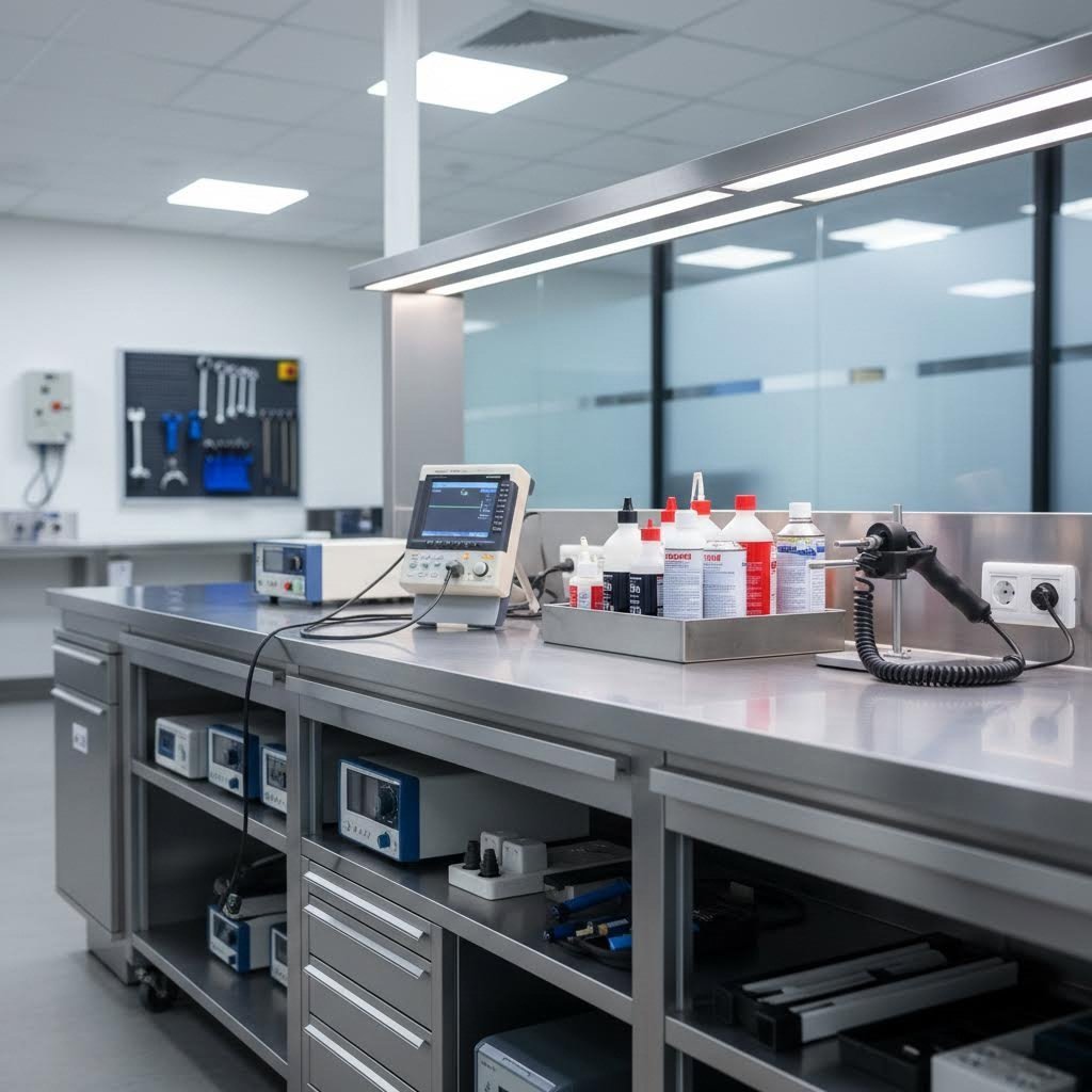
Ovladali ste tehnične podrobnosti – vrste napak, metode odkrivanja, merila za sprejemljivost in industrijske standarde. Zdaj se pojavi praktično vprašanje: kako to vse dejansko uvesti v dejanskem kovalnem procesu? Prepad med vedanjem, kaj pregledovati, in gradnjo vzdržnega programa pregledovanja pogosto določa, ali se cilji kakovosti dosledno dosegajo.
Učinkovita implementacija NDT-ja zajema celoten življenjski cikel proizvodnje kovanja. Od trenutka, ko surovine pridejo v vaš objekt, do preverjanja končnega izdelka, točke pregleda zagotavljajo zgodnje odkrivanje napak – ko so stroški odprave nižji in je vpliv na stranko zmanjšan na minimum.
Vključitev NDT-ja v vaš delovni proces kovanja
Predstavljajte si svoj program NDT-ja kot niz kakovostnih vrat, postavljenih na strategičnih točkah v celotnem proizvodnem procesu. Vsaka vrata odkrijejo določene vrste napak, preden se širijo v nadaljnje operacije.
Pregled prihajajočega materiala
Kakovost se začne že pred začetkom kovanja. Pri kovanih delih iz legirane jeklene in ogljikove jeklene zlitine pregled prihajajočih bilcev določi osnovo za kakovost:
- Ultrazvočno preverjanje: Zaznava notranje napake, ločevanje in ostankov votlin v palicah ali bilcih
- Pregled površine: Vizualni in MT/PT pregled za ukrivljenosti, nastike in površinske razpoke iz primarnega valjanja
- Preverjanje materiala: Pozitivna identifikacija materiala (PMI) ali razvrščanje z vrtinčnimi tokovi potrdi pravo vrsto zlitine
- Pregled dokumentacije: Preverite, ali potrdila mlinov ustrezajo zahtevom za nakup
Po Vodnik za zagotavljanje kakovosti podjetja Singla Forging , preverjanje kemične sestave, čistosti in sledljivosti izdelkov iz slitega materiala ali ingotov je ključno – potrjevanje materiala in pregled ob prevzemu pomagata zagotoviti, da se uporabljajo le odobreni razredi materiala, kar zmanjšuje tveganje notranjih napak ali nepričakovanega mehanskega vedenja.
Točke medprocesnega pregleda
Strateški pregled med proizvodnjo omogoča odkrivanje težav, preden vplivajo na celotno serijo:
- Vizualni pregled po kovanju: Takojšnji pregled za očitne napake – nezapolnjene dele, razpoke v lisici, znake obrabe orodja
- Prvotni pregled: Celovit nedestruktivni pregled prvih izdelanih kosov potrdi nastavitev orodja in procesnih parametrov
- Statistično vzorčenje: Občasni pregled ohranja nadzor nad procesom skozi celotno proizvodnjo
- Preverjanje toplotne obdelave: Pregled po toplotni obdelavi ujame kalilne razpoke in napake pri termični obdelavi
Pri posebnih postopkih izdelave kovanega jekla, ki proizvajajo specializirane komponente, se pogostost pregleda med procesom pogosto poveča v primerjavi s standardno proizvodnjo – stroški zgodnjega odkrivanja težav so po vrhu v primerjavi s stroški zavrnitve kasneje v procesu.
Zahteve za pripravo površine glede na metodo
Vsaka metoda netruhnega preiskovanja zahteva določene pogoje površine za zanesljive rezultate. Pri pregledu kovanih rodnikov ali drugih natančnih komponent pravilna priprava preprečuje napačne ocene in neodkriti napaki:
| Metoda NDT | Zahtevanja površine | Koraki priprave |
|---|---|---|
| Ultrazvočno testiranje | Gladka površina (največ 250 mikropalcev), čista, suha | Odstranite luske, brušenje grubi površini, odmaščevanje, nanesele kontaktne sredstvo |
| Magnetna prahova defektoskopija | Čista, brez olja/maziva, dovoljene tanke prevleke | Očistite s topilom, odstranite debelo lusko, temeljito posušite |
| Kapilarno testiranje | Čista, suha, brez vseh onesnažil | Odmaščevanje s topilom, odstranite vse prevleke/lesk z območja pregleda, popolnoma posušite |
| Vrtinčni tokovi | Enakomerna površinska stanja, minimalen oksid | Lahko čiščenje, zagotovi enakomerno teksturo površine |
| Rentgenski | Brez razpuščenega mulja ali odpadkov, ki vplivajo na sliko | Odstrani razpuščene materiale, zagotovi stabilnost pozicioniranja dela |
Ali lahko kujete nerjavnosti in hkrati ohranite površine, pripravljene za pregled? Seveda – a vendar imajo avstenitne sorte drugačno pripravo kot ogljikova jekla. Njihove oksidne plasti se obnašajo drugače, metode čiščenja pa morajo izogibati onesnaževanju s kloridi, ki bi lahko povzročili korozijo pod napetostjo.
Zadnja preverba izdelka
Pred odpremo končni pregled potrdi, da komponente ustrezajo vsem specifikacijskim zahtevam:
- Popolno NDT po strankini specifikaciji: Vse zahtevane metode izvedene v skladu z ustreznimi standardi
- Preverjanje dimenzij: Potrdi ključne dimenzije, ki ustrezajo tolerancam na risbi
- Potrditev površinske obdelave: Preverite zahteve za obdelavo funkcionalnih površin
- Paket dokumentacije: Zberite potrdila, poročila o testih in zapise sledljivosti
Pri posebnih aplikacijah kovanja iz nerjavnega jekla končni pregled pogosto vključuje dodatne preizkuse korozije ali specializirane preglede poleg standardnih zahtev NDT.
Sodelovanje s kovalnami, ki se osredotočajo na kakovost
Tu je dejavnost, ki jo mnoge nabavne ekipe prezrejo: vaša naknadna obremenitev z NDT neposredno odraža kakovost delovanja dobavitelja v napredni fazi. Delo s dobavitelji, ki vzdržujejo stroge notranje kontrole kakovosti, znatno zmanjša zahteve po pregledu v vaši napravi.
Ko dobavitelji vlagajo v celovite sisteme kakovosti in medprocesne preglede, njihovi stranke imajo koristi v obliki zmanjšanih zahtev za vhodni pregled, nižjih stopenj zavrnitve in hitrejšega časa do proizvodnje za kritične komponente.
Kaj ponujajo dobavitelji, usmerjeni v kakovost
Proizvajalci kovancev, ki so zavezani kakovosti, ponujajo običajno:
- Certifikat IATF 16949: Prikazuje zavezanost načelom kakovostnega upravljanja v avtomobilski industriji, ki so uporabna tudi v drugih panogah
- Lastne zmogljivosti NDT: Kontrola se izvaja kot sestavni del proizvodnje in ne kot dodatna aktivnost
- Dokumentacija nadzora procesov: Statistični dokaz o doslednem izvajanju kakovosti
- Inženirska podpora: Sodelovalni pristop pri razvoju specifikacij in reševanju težav
- Sistemi sledljivosti: Popolna dokumentacija od surovine do končnega izdelka
Pri avtomobilskih aplikacijah, ki zahtevajo natančno vroče kovanje komponent, kot so rokavi nihal in gonilni gredi, Shaoyi (Ningbo) Metal Technology to kakovostno usmerjeno prakso ponazarja. Njihova certifikacija IATF 16949 in lastne inženirske zmogljivosti zagotavljata, da komponente ustrezajo točnim specifikacijam – od hitrega prototipiranja do serijske proizvodnje – ter tako zmanjšujeta delež zavrnitev pri nadaljnjih NDT kontrolah za njihove stranke.
Ocenjevanje sistemov kakovosti dobaviteljev
Pri ocenjevanju potencialnih dobaviteljev kovanja preverite naslednje kazalnike kakovosti:
- Stanje certifikacije: Veljavni ISO 9001 najmanj; IATF 16949 za avtomobilsko industrijo; AS9100 za letalsko industrijo
- Možnosti NDT: Lastna kontrolna oprema in usposobljeno osebje
- Kontrola procesov: Uvedba statistične kontrole procesov, načrti kontrole, postopki reakcije
- Zgodovinske zmogljivosti: Stopnje zavrnitve PPM, dobava v roku, ocenjevalne liste strank
- Neprekinjeno izboljšanje: Dokazila o tekočih pobudah za izboljševanje kakovosti
Zmanjšanje obsega pregledovanja prek partnerstva s dobavitelji
Ekonomsko je ugodno: vsaka napaka, ki jo vaš dobavitelj odkrije notranje, stane le del vsote, ki bi jo stala, če bi bila odkrita v vaši obratih – in zgolj majhen delež stroškov zaradi napak v uporabi. Strateška partnerstva z dobavitelji ustvarijo skupne motive za izboljševanje kakovosti:
- Zmanjšana vhodna kontrola: Certificirani dobavitelji z dokazanim učinkom lahko izpolnjujejo pogoje za preskakovanje serij ali zmanjšano vzorčenje
- Hitrejši proizvodni cikli: Zanesljiva kakovost prejetih materialov odpravi ovire pri pregledih
- Nižji skupni stroški: Zmanjšano zavrnjevanje, predelava in garancijski stroški nadoknadita morebitno višjo ceno dobavitelja
- Tehnično sodelovanje: Skupno reševanje težav izboljša rezultate tako pri načrtovanju kot pri proizvodnji
Kot Podrobni vodnik Baron NDT poudarja, da obravnava NDT kot dinamični proces pomeni zbiranje povratnih informacij o napačnih opozorilih ali neopazjenih napakah za izboljšanje metod in usposabljanja. Dobavitelji, ki sledijo filozofiji kakovosti, sprejmejo to filozofijo stalnega izboljševanja ter izpopolnjujejo svoje postopke na podlagi povratnih informacij strank in podatkov o dejanski uporabi.
Gradnja dolgoročnih odnosov glede kakovosti
Najučinkovitejši NDT programi segajo čez stene vaše naprave in vključujejo celotno dobavno verigo. Ko vaš dobavitelj kovanin kaže enako zavezanost kakovosti kot jo zahtevate vi, je rezultat brezhiben sistem kakovosti, ki odkrije napake na najzgodnejši možni točki – kar zmanjša stroške in poveča zanesljivost.
Ali že kupujete kovane jeklene zlitine za kritične konstrukcijske aplikacije ali kovane cevne fitinge iz ogljikovega jekla za industrijsko uporabo, kakovost dobavitelja neposredno vpliva na obseg vašega dela pri kontroli in zanesljivost končnega izdelka. Vlaganje časa v kvalifikacijo dobaviteljev in spremljanje njihove učinkovitosti se obrestuje s pomanjšanim obsegom pregledov, manj pritožb strank in močnejšim konkurenčnim položajem.
Nedestruktivno testiranje kovanov končno služi enemu namenu: zagotavlja, da vsak del, ki zapusti vaš objekt ali prihaja od vaših dobaviteljev, ustreza kakovostnim standardom, ki jih pričakujejo vaši stranke in jih zahtevajo vaše aplikacije. Z uvedbo sistematičnih programov pregleda skozi celoten življenjski cikel kovanja ter sodelovanjem z dobavitelji, ki se osredotočajo na kakovost, ustvarite temelj za dosledno in zanesljivo zmogljivost.
Pogosta vprašanja o nedestruktivnem testiranju kovanov
1. Kateri so 4 glavni tipi NDT testiranja za kovance?
Štirje primarni NDT postopki za kovanke so ultrazvočno testiranje (UT) za notranje napake, magnetno delčno testiranje (MT) za površinske napake na feromagnetnih materialih, kapljično penetrantsko testiranje (PT) za površinske nezveznosti na vseh materialih ter radiografsko testiranje (RT) za popolno notranje slikanje. Vsak postopek cilja določene vrste napak – UT odlično najde poroznost in vključke globoko znotraj materiala, medtem ko se MT in PT specializirata za odkrivanje površinskih razpok, prekrivanj in šivov. Dobavitelji kovank, ki se osredotočajo na kakovost, kot so tisti s certifikatom IATF 16949, običajno uporabljajo več metod, da zagotovijo celovito pokritost napak.
2. Kaj je netrujno testiranje jeklenih kovank?
Nedestruktivno preizkušanje jeklenih kovancev uporablja metode pregleda, ki ovrednotijo celovitost sestavnih delov, ne da bi poškodovali ali spremenili dela. Za razliko od destruktivnega preizkušanja, pri katerem se vzorci uničijo, NDT omogoča pregled vsakega posameznega kovanca, ki nato še vedno lahko vstopi v proizvodnjo. Pogoste tehnike vključujejo ultrazvočno preizkušanje z uporabo frekvenc 1–5 MHz za odkrivanje notranjih napak, magnetno prahovno defektoskopijo za površinske napake in kapilarno defektoskopijo za odkrivanje razpok. Te metode sledijo standardom, kot so ASTM E2375 in A388, ki so posebej razviti za pregled kovanja, ter zagotavljajo, da jekleni sestavni deli izpolnjujejo varnostne zahteve za uporabo v letalstvu, avtomobilski industriji in tlačnih posodah.
3. Katerih 8 pogosto uporabljenih NDT tehnik?
Osem najpogosteje uporabljenih NDT metod vključuje: vizualno preizkušanje (VT) kot metodo zahtevne kontrole, ultrazvočno preizkušanje (UT) za notranje nezveznosti, radiografsko preizkušanje (RT) za popolno volumetrično slikanje, magnetoprahno preizkušanje (MT) za površinske napake v feromagnetnih materialih, barvno penetrantsko preizkušanje (PT) za površinske razpoke, vrtinčno tokovno preizkušanje (ET) za hitro površinsko presojo, preizkušanje akustične emisije (AE) za zaznavanje aktivnih napak in preizkušanje puščanja (LT) za preverjanje tesnosti pod tlakom. Pri kovaninah se najpogosteje uporabljajo UT, MT, PT in RT, pogosto tudi v kombinaciji, da se zagotovi, da nobena vrsta napake ostane neopazena.
4. Kako prepoznamo, ali je del kovan ali lit?
Kovani deli kažejo značilne lastnosti, ki jih razlikujejo od litin. Pri kovanju z odprtim orodjem se običajno pojavijo sledi orodja, kjer je bila obdelovanka oblikovana – pogosto v obliki več ravnih vtisov zaradi ponavljajočih se operacij kladiva ali prese. Notranjost kovanih komponent ima usmerjen tok zrna, ki sledi konturi dela, kar zagotavlja nadpovprečno trdnost. Litine kažejo naključno strukturo zrn in lahko prikazujejo poroznost zaradi strjevanja. NDT metode lahko razkrijejo te razlike: ultrazvočno testiranje kaže različne odzive signalov zaradi usmerjenosti zrn, makroetšenje pa razkrije značilne črte toka, ki so edinstvene za kovane materiale.
5. Katera NDT metoda je najbolj primerna za odkrivanje notranjih napak v kovankah?
Ultrazvočno testiranje je primarni način za odkrivanje notranjih napak v kovanem delu zaradi odlične prodornosti in občutljivosti na prostorske napake. Z uporabo frekvenc med 1–5 MHz, odvisno od debeline materiala in zrnaste strukture, UT učinkovito prepozna poroznost, krčne votline, vključke in vodikove ploščice, skrite globoko znotraj komponente. Pri zapletenih geometrijah, kjer je dostop UT omejen, radiografsko testiranje zagotavlja dopolnilno notranjo pokritost. Kritične aplikacije pogosto kombinirajo oba načina – UT zagotavlja informacije o globini in visoko občutljivost na ravninske napake, medtem ko RT zajame napake ne glede na usmerjenost in ustvari trajno dokumentacijo.