 Malé dávky, vysoké štandardy. Naša služba rýchlejho prototypovania urobí overenie rýchlejšie a jednoduchšie —

Na mieru vyrobené rezanie hliníka: Zostavte si zliatinu, hrúbku a metódu

Pochopenie základov výroby vlastných rezných hliníkových dielov
Či už navrhujete súčiastky pre letecký priemysel, budujete architektonické prvky alebo riešite DIY projekt na víkend, pravdepodobne sa stretnete s hliníkom. Ale tu je háčik – hliník z obchodu zriedka presne vyhovuje vašim špecifickým požiadavkám. Práve vtedy prichádza na rad výroba vlastných rezných hliníkových dielov, ktorá premení surový materiál na presne tvarované komponenty prispôsobené vašim individuálnym požiadavkám.
Výroba vlastných rezných hliníkových dielov označuje presné montážne služby tvarovanie hliníkových plechov, dosiek a profilov na presné rozmery pomocou rôznych rezacích technológií. Na rozdiel od zakúpenia predrezaného materiálu v obchode vám tento proces umožňuje určiť rozmery, tolerancie a kvalitu rezov, ktoré váš projekt vyžaduje. Predstavte si to ako rozdiel medzi kúpou obleku na mieru a kúpou hotového obleku.
Tento sprievodca slúži ako komplexný učebný zdroj pre pochopenie, ako efektívne rezať hliník. Objavíte kľúčové vzťahy medzi výberom zliatiny, hrúbkou materiálu a voľbou metódy rezu. Na konci budete mať znalosti na rozhodnutia – či už pracujete s miestnou dielňou na spracovanie kovov alebo odovzdávate súbory online službe na rezanie.
Čo robí rezanie hliníka prispôsobené
„Prispôsobené“ pri prispôsobenom rezaní hliníka zahŕňa niekoľko kľúčových prvkov, ktoré ho odlišujú od štandardnej výroby:
- Presná kontrola rozmerov: Špecifikujete presné rozmery až na tisíciny palca namiesto prijatia štandardných veľkostí
- Flexibilita tvaru: Komplexné geometrie, zapletené vzory a jedinečné profily sa stávajú možnými vďaka pokročilým rezacím technológiám
- Výber materiálov: Vyberiete si konkrétnu triedu zliatiny, ktorá zodpovedá požiadavkám vašej aplikácie na pevnosť, odolnosť voči korózii a spracovateľnosť
- Špecifikácia tolerancií: Kritické aplikácie vyžadujú úzke tolerancie, ktoré sériovo vyrábané diely jednoducho nemôžu zaručiť
Podľa odborníci z priemyslu , výroba na mieru z hliníka sa v súčasnej ére inovácií a dizajnu stala kľúčovým pilierom mnohých priemyselných odvetví. Tento proces zahŕňa rezanie, tvarovanie, zváranie a montáž hliníka do výrobkov, ktoré slúžia ako funkčným, tak estetickým účelom.
Prečo je dôležitá presnosť pri spracovaní hliníka
Hliník predstavuje pre spracovateľov fascinujúcu paradoxnosť. Jeho vlastnosti ho robia mimoriadne populárnym – práve tieto vlastnosti však spôsobujú špecifické výzvy pri rezaní.
Hliník je ľahký, stabilný s pevnosťou v ťahu, ktorá sa približuje ocele, má prirodzenú odolnosť voči korózii a je vynikajúcim vodičom tepla. Tieto vlastnosti uľahčujú obrábanie a umožňujú vysoké rezné rýchlosti, ale zároveň znamenajú, že nesprávne rezné techniky môžu rýchlo viesť k deformácii materiálu, tvorbe nánosov na hrane a strate rozmernosti.
Keď pracujete s hliníkovým plechom, presnosť neznamená len dosiahnutie správnych rozmerov. Vysoká tepelná vodivosť materiálu spôsobuje rýchle odvádzanie tepla počas rezu – čo je výhoda pri predchádzaní deformácii, ale zároveň faktor, ktorý vyžaduje správnu techniku. Medzitým môže sklon hliníku k tvorbe lepiacich sa triesok negatívne ovplyvniť kvalitu rezania, ak nie sú rezné parametre optimalizované pre konkrétnu zliatinu.
Pre projekty spracovania hliníka, až po výrobu autodiely po výrobou vlastných nápisov, porozumenie týchto správaní materiálu pomáha pri výbere správnej metódy rezu a efektívnej komunikácii so svojím výrobným partnerom. Či už potrebujete orezať hliník pre prototyp skrine alebo vyrobiť stovky identických konzol, základy zostávajú rovnaké: prispôsobte svoju zliatinu, hrúbku a spôsob rezu, aby ste dosiahli optimálne výsledky.
Počas tohto sprievodcu sa naučíte ovládať päť hlavných metód rezného spracovania, pochopiť správanie rôznych zliatin pri rôznych rezacích podmienkach a pripraviť špecifikácie, ktoré predchádzajú nákladným chybám. Považujte tento sprievodcu za svoju cestovnú mapu k úspešným vlastným projektom strihania hliníka.
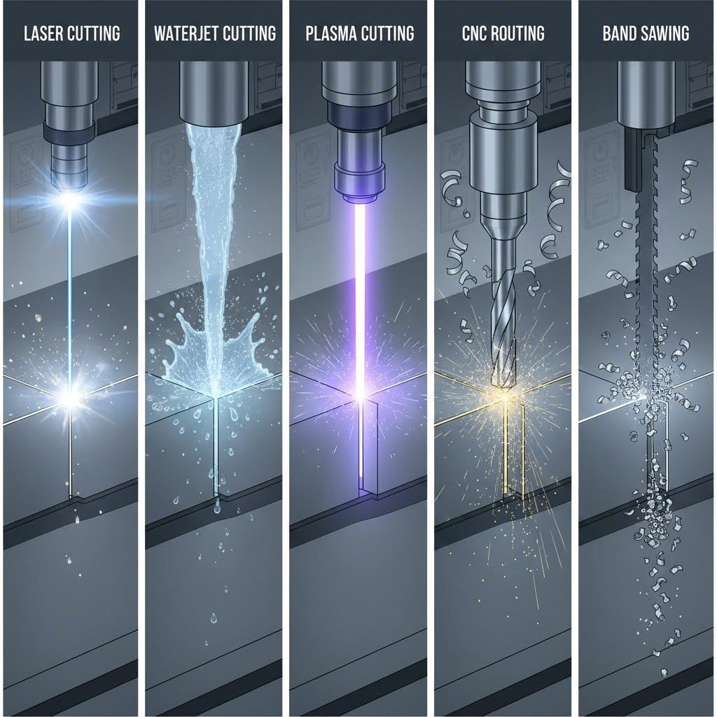
Päť metód rezného spracovania hliníka v porovnaní
Teraz, keď rozumiete tomu, čo robí rezanie hliníka individuálnym, preskúmajme technológie, ktoré ho umožňujú. Každá rezacia metóda inak interaguje s jedinečnými vlastnosťami hliníka – a výber nesprávnej metódy môže znamenať rozdiel medzi dokonalými okrajmi a frustrujúcim opakovaním práce. Tu je komplexný prehľad piatich hlavných metód používaných na rezanie hliníka v profesionálnych výrobných podmienkach .
Laserové rezanie pre presné spracovanie hliníka
Predstavte si, že sústredíte slnečné svetlo cez lupy a potom túto intenzitu násobíte tisíckrát. V podstate takto funguje laserový rezací stroj. Táto technológia využíva vysoce zameraný lúč svetla – zvyčajne z CO2 alebo vláknového lasera – na roztavenie, odparovanie alebo spálenie materiálu po programovanej dráhe.
Čo sa týka hliníku, preferovanou voľbou sa stali vláknové lasery. Zvládajú odrazivosť hliníka lepšie ako staršie CO2 systémy a dosahujú vynikajúce výsledky pri tenkých až stredne hrubých materiáloch. Podľa odborných zdrojov je laserové rezanie výnimočne vhodné pre hliníkové plechy zvyčajne do hrúbky 20 mm (približne 0,75 palca), pričom maximálna hrúbka závisí od výkonu lasera a konkrétnej zliatiny, ktorá sa spracováva.
Čo robí laserové rezanie vynikajúcim pri presnej práci? Táto technológia vytvára extrémne úzky rez – šírku materiálu odstráneného počas rezu – čím minimalizuje odpad a umožňuje komplikované návrhy. Kvalita hrán je zvyčajne hladká a čistá, často nevyžaduje dodatočné dokončenie. Vysoká tepelná vodivosť hliníka však znamená, že tepelne ovplyvnená zóna, aj keď malá, si vyžaduje zváženie pri aplikáciách, kde sú dôležité vlastnosti materiálu.
- Najlepší rozsah hrúbky: Až 0,5 palca (optimálne pod 0,25 palca)
- Bežná tolerancia: ±0,005 palca
- Kvalita hrany: Vynikajúca, hladká s minimálnym tvorením hrotov
- Teplom ovplyvnená zóna: Malá, ale prítomná – môže ovplyvniť kalenie u kalených zliatin
Waterjet vs plazmové rezanie pri hrubých hliníkových platniach
Keď sa zväčšuje hrúbka vašej hliníkovej platne, dve metódy reznia súperia o prevahu: waterjet a plazmové rezanie. Každá z nich používa zásadne odlišný prístup k oddeleniu kovu a porozumenie týmto rozdielom vám pomôže robiť lepšie rozhodnutia pre vaše projekty.
Režanie vodným paprskom používa vysokotlaký prúd vody – často zmiešanej s abrazívnymi časticami, ako je granát, na odstraňovanie materiálu pozdĺž rezného pásma. Pri prevádzkových tlakoch až do 90 000 PSI tento postup chladného rezania úplne eliminuje tepelne ovplyvnené zóny. Váš hliník si zachováva pôvodné vlastnosti materiálu po celom okraji.
Táto metóda reže kov bez tepelného skreslenia, čo ju robí ideálnou pri práci s kalenými zliatinami, ako je 7075-T6, kde je nevyhnutné zachovať tepelné spracovanie. Vodný lúč dokáže spracovať prakticky akúkoľvek hrúbku hliníkovej dosky, aj keď rýchlosť rezania výrazne klesá so zvyšujúcou sa hrúbkou materiálu.
Plazmové rezanie zvolila opačný prístup. Používa urýchlený prúd ionizovaného plynu – ktorý dosahuje teploty až 45 000 °F – na roztavenie elektricky vodivých materiálov. Moderné CNC plazmové systémy kombinujú túto rezaciu silu s presnosťou riadenou počítačom.
Plazma sa presadzuje v rýchlosti a nákladovej efektívnosti pri rezaní stredne hrubého až hrubého hliníka. Plazmový systém dokáže prerezať hliník hrúbky 0,5 palca výrazne rýchlejšie ako vodný lúč, čo ho robí atraktívnym pre výrobné prostredia. Intenzívne teplo však vytvára výraznejšiu tepelne ovplyvnenú zónu a kvalita rezu zvyčajne vyžaduje viac dodatočnej úpravy v porovnaní s rezmi vodným lúčom.
CNC frézovanie a pílenie
Nie každá aplikácia na rezanie hliníka vyžaduje termické alebo abrazívne procesy. Mechanické metódy rezania – CNC frézovanie a pílenie – zostávajú cennými nástrojmi v arzenále spracovateľa.
Frezovanie CNC používa rotujúce rezné nástroje riadené počítačovým číselným ovládaním na odstraňovanie materiálu. Predstavte si to ako metódu strihacieho stroja pre hliník, pri ktorej frézovací vrták fyzicky odstraňuje materiál namiesto jeho roztavenia alebo erozie. Táto metóda vyniká pri tvorbe komplexných trojrozmerných tvarov a dobre funguje pri rôznych hrúbkach hliníka.
Výhody? Žiadna tepelne ovplyvnená zóna, vynikajúca rozmerná presnosť a schopnosť vytvárať dutiny, drážky a fazety, ktoré iné rezné metódy nedokážu. Kompromisom je rýchlosť – frézovanie beží zvyčajne pomalšie ako laserové alebo plazmové rezanie pri jednoduchých 2D profiloch.
Pílový rez používa zubaté čepele (kruhové, pásové alebo vratné) na mechanické rezanie hliníka. Je to najjednoduchší a najnákladovo efektívnejší spôsob rezania priamych rezov a jednoduchých tvarov. Hoci neprekoná iné metódy pri komplikovaných dizajnoch, rezanie pílou spoľahlivo zvládne všetko od tenkých plechov až po hrubé platne.
Komplexné porovnanie metód
Voľba správneho stroja na rezanie kovu pre váš hliníkový projekt vyžaduje súčasné zváženie viacerých faktorov. Táto tabuľka zhrňuje praktické rozdiely, ktoré potrebujete poznať:
| Metóda | Najvhodnejší rozsah hrúbok | Kvalita hrany | Tolerancia | Rýchlosť | Najlepšie použitie |
|---|---|---|---|---|---|
| Laserového rezania | Až do 0,5" (optimálne pod 0,25") | Vynikajúce – hladký rez, minimálny burin | ±0.005" | Veľmi rýchle pri tenkom materiáli | Komplikované návrhy, presné diely, skrine elektroniky |
| Režanie vodným paprskom | Akákoľvek hrúbka (bežne až do 6") | Dobré – mierne zrnitosť, žiadne stopy od tepla | ±0,005" až ±0,010" | Pomalý až stredne silný | Hrubé platne, teplotne citlivé zliatiny, letecké komponenty |
| Plazmové rezanie | 0,125" až 2" | Stredná – môže vyžadovať odstránenie hrúb | ±0,015" až ±0,030" | Veľmi rýchlo | Nosné konštrukcie, klimatizácie, výroba vo veľkom rozsahu |
| Frezovanie CNC | Až do 2" (závisí od stroja) | Dobrá – čistý mechanický rez | ±0.005" | Mierne | Komplexné 3D tvary, dutiny, vývessky |
| Pílový rez | Akákoľvek hrúbka | Priemerná – môže vyžadovať dokončenie | ±0,030" až ±0,060" | Stredná až vysoká | Rovné rezy, hrubé rezanie, tyčový polotovar |
Zóny ovplyvnené teplom a integrita materiálu
Tu je niečo, čo si mnohí výrobcovia nevšímajú: tepelné metódy rezania nielen odstraňujú materiál – dočasne menia hliník okolo rezu. Táto zóna ovplyvnená teplom (HAZ) môže zmeniť mechanické vlastnosti, ovplyvniť odolnosť voči korózii a ohroziť rozmernú stabilitu pri presných aplikáciách.
Laserové rezanie vytvára najmenšiu HAZ zo všetkých tepelných metód, a to vďaka svojej sústredenej energii a vysokéj rýchlosti rezania. Podľa odborníkov na obrábanie kovov , sústredená energia lasera znamená, že zóna ovplyvnená teplom je veľmi malá, čo spôsobuje minimálne tepelné deformácie – čo je kľúčové pre zachovanie mechanických a štrukturálnych vlastností hliníka.
Plazmové rezanie naopak vytvára väčšiu zónu ovplyvnenú teplom kvôli extrémne vysokým teplotám. Pri konštrukčných aplikáciách, kde tvrdosť hrany nie je kritická, to zriedka pôsobí problém. Avšak pri presných komponentoch alebo tepelne spracovaných zliatinách sa tento rozdiel stáva významným.
Vodný lúč a mechanické rezanie (frézovanie, pílenie) úplne eliminujú tepelné vplyvy. Ak vaša špecifikácia hliníkovej platne vyžaduje nulový tepelný dopad – napríklad pri leteckých aplikáciách alebo komponentoch, ktoré budú následne anodizované – tieto studené rezné procesy zachovávajú plnú integritu materiálu.
Pochopenie týchto rozdielov vám umožní vybrať optimálnu rezaciu metódu na základe vašich konkrétnych požiadaviek. Rezná technológia je však len časťou rovnice – rovnako dôležitá je zliatina, ktorú režete, a práve to si teraz podrobnejšie preberieme.
Hliníkové zliatiny a ich rezné vlastnosti
Vybrali ste si spôsob rezu – ale tu je otázka, ktorá chytá dokonca aj skúsených výrobcov: ktorú zliatinu hliníka by ste mali naozaj rezať? Na rozdiel od voľby medzi mosadzou a bronzom, kde sú rozdiely zrejmé, sa zliatiny hliníka na prvý pohľad môžu zdať navzájom zameniteľné. Nie sú. Zliatina, ktorú vyberiete, priamo ovplyvňuje kvalitu hrany, rýchlosť rezania a to, či bude váš hotový diel plniť očakávané požiadavky.
Predstavte si zliatiny hliníka ako kávové zmesi. Čistý hliník je pre väčšinu aplikácií príliš mäkký – rovnako ako by neupravené nepražené zrná nepotešili vašu rannú rutinu. Výrobcovia pridávajú prvky ako horčík, kremík, zinok a meď, aby vytvorili zliatiny so špecifickými prevádzkovými vlastnosťami . Porozumenie týmto rozdielom vás mení z osoby objednávajúcej „hliník“ na osobu, ktorá presne určuje, čo jej projekt vyžaduje.
Voľba medzi hliníkom 6061 a 5052
Tieto dve zliatiny dominujú v objednávkach na výrobu vlastných hliníkových rezov – a to z dobrého dôvodu. Obe ponúkajú vynikajúcu všestrannosť, ale v rôznych situáciách sa prejavujú inak. Vedieť, kedy zvoliť ktorú, ušetrí peniaze a zabráni problémom s výkonom v budúcnosti.
5052-H32 Hliník si zaslúži povesť pracovného koníka medzi zliatinami. Prídavok horčíka a chrómu k čistému hliníku zabezpečuje vynikajúcu odolnosť voči korózii pri zachovaní vynikajúcej tvárnosti. Tá označenie H32? Znamená, že materiál bol umelo zhutnený a stabilizovaný, čím je dostatočne ťažný na studené spracovanie – vrátane ohýbania – bez rizika praskania.
- Pevnosť v ťahu: Približne 33 000 PSI – postačujúce pre väčšinu nestrukturných aplikácií
- Odpornosť na koroziu: Vynikajúca, najmä v námorných a vonkajších prostrediach
- Svarovateľnosť: Vynikajúca – vytvára silné, spoľahlivé zvary
- Tvariteľnosť: Superior – ľahko sa ohýba bez praskania
- Najlepšie aplikácie: Námorné komponenty, palivové nádrže, vonkajšie vývessky, architektonické panely a akýkoľvek projekt vyžadujúci ohýbanie po reze
Podľa Odborníci na materiály spoločnosti SendCutSend , 5052 H32 je jedným z ich najobľúbenejších materiálov, ktorý ponúka vynikajúcu rovnováhu medzi odolnosťou a cenou pre výrobné projekty.
6061-T6 Hliník zvyšuje výkon, keď sa pevnosť stane kritickou. Tto zliatina obsahuje horčík a kremík, pričom označenie T6 indikuje tepelné spracovanie a umelé starnutie – procesy, ktoré výrazne zvyšujú pevnosť v ťahu aj únavovú pevnosť.
- Pevnosť v ťahu: Približne 45 000 PSI – o 32 % pevnejšie ako 5052
- Pevnosť na vytiahnutie: 276 MPa, vhodné pre konštrukčné komponenty
- Obrateľnosť: Vynikajúce – umožňuje vysokorýchlostné operácie s vynikajúcim povrchovým dokončením
- Svarovateľnosť: Dobré, hoci zváranie zníži pevnosť v tepelne ovplyvnenej zóne
- Najlepšie aplikácie: Nosné rámy, autokomponenty, strojové súčasti a presné skrinky, kde je dôležitejšia pevnosť než tvárnenie
Tu je kľúčový rozdiel pre rozhodnutia pri rezaní: 6061 sa skvelo obrába, ale neohýba sa tak predvídateľne ako 5052. Ak váš projekt vyžaduje ostré ohyby po rezaní, 5052 je zvyčajne bezpečnejšou voľbou. Potrebujete maximálnu pevnosť bez ohýbania? 6061 ju poskytne.
Kedy má zmysel použiť vysokopevnostný 7075
Niekedy musia hárky z hliníka súťažiť so šteklom. Práve tu prichádza do úvahy zliatina 7075-T6. Výrazné množstvá zinku, horčíka a medi posúvajú pevnosť tejto zliatiny do oblasti blízkej titanu – a to pri zachovaní výhody hliníka v hmotnosti.
- Pevnosť v ťahu: Približne 83 000 PSI – takmer dvojnásobok oproti 6061
- Pevnosť na vytiahnutie: 503 MPa, najvyššia hodnota medzi bežnými hliníkovými zliatinami
- Odolnosť proti únave: Vynikajúca – kritická pre komponenty vystavené opakovaným namáhacím cyklom
- Odpornosť na koroziu: Nižšia ako u 5052 alebo 6061 – môže vyžadovať ochranné povlaky
- Svarovateľnosť: Zlá – všeobecne neodporúčaná pre zvárané zostavy
- Najlepšie aplikácie: Súčiastky pre letecký priemysel, vysokovýkonné športové vybavenie, rám bicykla a akékoľvek aplikácie vyžadujúce maximálny pomer pevnosti k hmotnosti
Komuže? Zliatina 7075 je nákladnejšia na libru a predstavuje výzvu pri rezaní. Jej tvrdosť zvyšuje opotrebovanie nástrojov a tepelná úprava, ktorá jej dodáva pevnosť, ju takmer znemožňuje ohýbať bez praskania. Ako odborníci na obrábanie uvádzajú, zliatina 7075 vyžaduje špecifické nastavenie parametrov kvôli nižšej obrábateľnosti v porovnaní s 6061.
Pochopenie zliatiny 3003-H14 pre všeobecné aplikácie
Nie každý projekt vyžaduje zliatiny s vysokou pevnosťou. Zliatina 3003-H14 ponúka najekonomickejšiu voľbu pre aplikácie, kde stačí stredná pevnosť. Táto zliatina obsahuje ako hlavný prísadový prvok mangán, čo poskytuje približne o 20 % vyššiu pevnosť než čistý hliník, pri zachovaní vynikajúcej tvarovateľnosti.
- Cena: Najekonomickejšia možnosť hliníkovej zliatiny
- Tvariteľnosť: Vynikajúce – ideálne na hlboké taženie a sústruženie
- Odpornosť na koroziu: Veľmi dobré pre všeobecné atmosférické vystavenie
- Najlepšie aplikácie: Chemické zariadenia, kuchynský riad, dekoratívne lišty a komponenty systémov HVAC
Ako voľba zliatiny ovplyvňuje výsledky rezania
Tu sa stretáva materiálová veda s praktickou výrobou. Zliatina, ktorú si vyberiete, priamo ovplyvňuje to, čo sa deje počas rezania – a čo budete musieť robiť neskôr.
Požiadavky na kvalitu hrán: Mäkšie zliatiny, ako napríklad 3003 a 5052, majú pri laserovom rezaní tendenciu tvoriť mierne viac hrotov v porovnaní s tepelne upravenou zliatinou 6061. Avšak všetky bežné hliníkové zliatiny dosahujú čisté rezy pri správne nastavenej výrobe. Pri aplikáciách anodizovaného hliníka je obzvlášť dôležitá hladkosť hrán, keďže proces anodizácie zvyšuje viditeľnosť povrchových nedokonalostí.
Vplyv rýchlosti rezania: Tvrdšie zliatiny vyžadujú nižšie rýchlosti rezania, aby sa zachovala kvalita hrany. Laser, ktorý reže plech 0,125 palca zliatiny 5052, môže ísť o 20 % rýchlejšie ako rovnaké zariadenie režuce zliatinu 7075. Tento rozdiel v rýchlosti sa priamo prejavuje na nákladoch pri výrobných sériách.
Požiadavky na dodatočné spracovanie: Zvážte, čo sa deje po rezaní. Ak je súčasťou procesu zváranie hliníka, zliatiny 5052 a 6061 to umožňujú jednoducho – zatiaľ čo 7075 v podstate eliminuje možnosť zvárania. Plánujete anodizáciu? Všetky štyri zliatiny dobre prijímajú anodizáciu, hoci 6061 zvyčajne poskytuje najkonzistentnejší estetický povrch.
Tento rámec – priradenie vlastností zliatiny k mechanickým, výrobným a dokončovacím požiadavkám vášho projektu – vám umožní s istotou určiť materiály. Výber zliatiny je však len polovicou úlohy. Hrúbka hliníkových plechov hrá rovnako dôležitú úlohu pri určovaní metódy rezu, ktorá dosiahne optimálne výsledky.

Priradenie hrúbky k správnej metóde rezu
Vybrali ste si zliatinu – teraz prichádza otázka, ktorá rozhodne o úspechu alebo neúspechu vášho rezacieho projektu: aká hrubá je vaša materiálová platňa? Znie to jednoducho, však? Napriek tomu voľba hrúbky spôsobuje väčšiu mätľu ako takmer ktorýkoľvek iný parameter pri rezaní hliníku na mieru. Porozumenie vzťahu medzi hrúbkou materiálu a metódou rezu mení odhad na dôkladné a sebavedomé rozhodovanie.
Tu je realita: rezacia metóda, ktorá poskytuje bezchybné výsledky pri tenkých hliníkových plechoch, môže pri hrubých platniach produkovať neprijateľnú kvalitu rezov. Fyzikálne zákony sa menia so zvyšujúcou sa hrúbkou – zmenšujú sa vzory odvodu tepla, vyvíjajú sa charakteristiky rezu a dosiahnuteľné tolerancie sa buď zužujú, alebo rozširujú v závislosti od procesu. Pozrime sa podrobne, čo presne funguje pre každú kategóriu hrúbky.
Pochopenie veľkosti kalibrov a špecifikácií hrúbky
Než sa pustíte do výberu metódy, musíte hovoriť jazykom hrúbky. Hrúbka hliníkovej plechovky sa udáva dvoma spôsobmi: v desatinných palcoch (alebo milimetroch) a číslach kalibru. Zmatečne fungujú kalibre nepriamo – vyššie čísla kalibru označujú tenší materiál.
Podľa Kalibračný systém Brown & Sharpe (známy aj ako American Wire Gauge), hliníková plechovka kalibru 18 má hrúbku približne 0,040 palca, zatiaľ čo oceľová plechovka kalibru 14 má hrúbku približne 0,075 palca. Tu je kľúčový bod, ktorý mnohí výrobcovia prehliadajú: hliník a oceľ používajú rôzne kalibračné systémy. Označenie kalibru 14 znamená pre tieto kovy veľmi odlišnú hrúbku.
Pre presnú prácu vždy uvádzajte hrúbku v desatinných palcoch namiesto používania čísel kalibru. Tým sa odstráni nejasnosť a zabezpečí sa, že váš partner pre výrobu oreže materiál presne podľa vašich požiadaviek. Pri používaní tabuľky kalibrov plechu overte, či je špecificky určená pre hliník – použitie tabuľky kalibrov ocele pre objednávky hliníka spôsobuje drahé chyby.
Možnosti rezu tenkého hliníkového plechu
Tenké plechy – materiál s hrúbkou pod 0,125 palca (približne zodpovedá hrúbke ocele kalibru 11) – ponúkajú najväčšiu flexibilitu vo výbere metódy rezu. Pri týchto hrúbkach tepelné procesy fungujú efektívne, mechanické metódy zostávajú praktické a dosiahnutie presných tolerancií je ľahko realizovateľné.
Čo robí tenké hliníkové plechy obzvlášť prispôsobivými? Teplo vznikajúce počas rezu sa rýchlo rozptýli vysokou tepelnou vodivosťou materiálu, čo nevyvoláva výrazné deformácie. Znížená hmotnosť materiálu tiež znamená menší odpor voči rezným silám, a to bez ohľadu na to, či ide o laserový lúč, vodný prúd alebo rotujúci nástroj.
- Rezanie laserom: Najvhodnejšia voľba pre aplikácie s tenkými hliníkovými plechmi. Vláknové lasery precízne režú materiál pod 0,125 palca veľkou rýchlosťou a s vynikajúcou kvalitou rezov. Očakávajte presnosť v toleranciách ±0,005 palca konzistentne. Najlepšie vhodné pre komplikované dizajny, tesne usporiadané vzory a sériovú výrobu, kde záleží na rýchlosti.
- Hydrolakové rezanie: Funguje dobre, ale pri tenkých materiáloch často predstavuje nadmerné riešenie. Proces ponúka výhody studeného rezania, ale je pomalší ako laser. Zvážte použitie vodného lúča pri práci s predanodizovanými alebo teplom citlivými špeciálnymi zliatinami.
- CNC frézovanie: Vynikajúce pre projekty kombinujúce 2D rezanie s 3D prvkami, ako sú drážky alebo fazety. Vytvára čisté mechanické rezy bez tepelne ovplyvnených zón. Rýchlosť je medzi laserom a vodným lúčom.
- Striehanie: Najekonomickejšia voľba pre rovné rezy na tenkých plechoch. Obmedzená na jednoduché geometrie, ale ponúka rýchle výsledky za nízky náklad.
Pri tenkom materiáli sa hlavnými rozhodovacími faktormi stávajú požiadavky na úpravu hrán, zložitosť dizajnu a objem výroby – nie schopnosť metódy. Takmer každá profesionálna rezacia technológia efektívne zvládne tenký hliník.
Stredná hrúbka: Univerzálny rozsah
Materiál s hrúbkou medzi 0,125 a 0,5 palca predstavuje optimálny rozsah, v ktorom sa viaceré rezacie metódy účinne prelámajú. Vaše rozhodnutie tu výrazne závisí od požiadaviek na kvalitu hrán, tolerančných špecifikácií a rozpočtových obmedzení.
Pri strednej hrúbke sa rezná dynamika výrazne mení. Šírka rezu – materiál odstránený počas rezania – nadobúda väčší význam pri výpočtoch výťažnosti materiálu. Naklonenie okraja, pri ktorom uhol rezu mierne odbočuje od pravého uhla, sa začína objavovať pri tepelných procesoch. Tolerance sa tiež stanú závislé od metódy a nie sú už všeobecne dosiahnuteľné.
- Rezanie laserom: U väčšiny zliatin hliníka zostáva vysoce účinná až do hrúbky približne 0,375 palca. Nad túto hrúbku sa kvalita okraja zhoršuje a rýchlosť rezu výrazne klesá. Vysokovýkonné vláknové lasery (6 kW a viac) tento rozsah predlžujú, ale za vyšších prevádzkových nákladov.
- Hydrolakové rezanie: S rastúcou hrúbkou sa stáva čoraz konkurencieschopnejšou. Nevytvára žiadnu tepelne ovplyvnenú zónu, zabezpečuje konzistentnú kvalitu okraja bez ohľadu na hrúbku a dodržiava tolerance zvyčajne v rozmedzí ±0,005 až ±0,010 palca. Chladný rezací proces úplne zachováva tepelné spracovanie zliatiny – čo je kritické pre tepelne spracované materiály ako 6061-T6 alebo 7075-T6.
- Plazmové rezanie: Zadáva do praktického rozsahu nad 0,125 palca. Zabezpečuje vynikajúcu rýchlosť rezu za nižšiu cenu za palec v porovnaní s laserom alebo vodným prúdom. Kompromis: širší rez, väčšia zóna ovplyvnenej teplom a tolerancie zvyčajne ±0,015 až ±0,030 palca. Vyžaduje odstránenie hriankov po reze.
- CNC frézovanie: Stále dobre funguje v tomto rozsahu. Výber nástroja sa stáva kritičtnejším – frézy s väčším priemerom efektívnejšie spracúvajú hrubší materiál. Vynikajúca voľba pri kombinovaní rezu s obrábacími operáciami.
Úspešné rezy hrubých hliníkových dosiek
Ak vaša hliníková doska presiahne 0,5 palca, možnosti sa dramaticky zužujú. Rezy hrubých dosiek vyžadujú metódy schopné zvládnuť významnú hmotnosť materiálu a zároveň zachovať primeranú kvalitu okrajov a rozmernú presnosť.
Podľa odborníkov na obrábanie zlyhávajú laserové rezače pri rezaní hrubého hliníka, pretože vysoká tepelná vodivosť kovu rýchlo odvádza sústredené teplo lasera, zatiaľ čo jeho odrazivý povrch môže odrážať energiu späť k reznému hlavici. U materiálu hrubšieho než približne 0,75 palca takmer vždy dosahuje lepších výsledkov vodný prúd.
- Hydrolakové rezanie: Jasný víťaz pri rezaní hrubých hliníkových platní. Zvládne materiál hrubý až 6 palcov alebo viac bez tepelnej deformácie. Kvalita rezu zostáva konzistentná bez ohľadu na hrúbku, aj keď rýchlosť rezu klesá úmerne k hrúbke. Pri liatinách triedy 7075 používaných v leteckom priemysle vodný prúd zachováva tepelné spracovanie, ktoré zabezpečuje mimoriadnu pevnosť zliatiny.
- Plazmové rezanie: Vhodné pre konštrukčné aplikácie, kde nie sú prísné požiadavky na úpravu okrajov. Reže rýchlejšie ako vodný prúd za výrazné úspory nákladov. Počítajte s väčšími tepelne ovplyvnenými zónami a plánujte ďalšie úkony na dokončenie povrchu.
- Rezanie pásovou pílkou: Najekonomickejší pre jednoduché rovné rezy hrubými doskami. Vytvára drsnejšie hrany, ktoré vyžadujú dodatočné opracovanie, ale dokáže spracovať prakticky akúkoľvek hrúbku, ktorú vaša dielňa fyzicky zvládne.
Ako hrúbka ovplyvňuje tolerancie a kvalitu hrán
Hrúbka materiálu neovplyvňuje len výber vhodnej metódy – priamo určuje aj dosiahnuteľnú presnosť. Porozumenie týchto vzťahov zabráni nadmernému špecifikovaniu tolerancií, ktoré zvyšujú náklady, alebo nedostatočnému špecifikovaniu, čo môže spôsobiť problémy pri montáži.
Šírka rezu sa zväčšuje s hrúbkou materiálu. Laser, ktorý reže hliník hrúbky 0,040 palca, môže vytvoriť rez široký 0,010 palca, zatiaľ čo ten istý laser pri materiáli hrúbky 0,375 palca vytvorí rez približne 0,025 palca. To je dôležité pri rozmiestňovaní dielov a výpočte výťažnosti materiálu.
Zkosenie hrán sa stáva výraznejším. Termické rezacie metódy vytvárajú mierne naklonené hrany na hrubom materiáli – horná časť rezu môže byť širšia ako spodná. Pri aplikáciách vyžadujúcich presný tvar uveďte, ktorý povrch musí mať rozmernú presnosť.
Tolerance sa zužujú za cenu. Dosiahnutie ±0,005 palca na hliníku hrúbky 0,063 palca stojí menej ako dosiahnutie tej istej tolerance na doske hrúbky 0,500 palca. Ak to váš prípad umožňuje, stanovenie tolerance ±0,010 palca u hrubších materiálov často výrazne zníži náklady projektu bez funkčných kompromisov.
Keď je teraz jasné priradenie hrúbky k správnemu spôsobu, ste pripravení preložiť požiadavky svojho projektu do špecifikácií, ktoré bude môcť vaša výrobná spoločnosť úspešne realizovať. Práve tento proces – príprava súborov a presná komunikácia špecifikácií – je miestom, kde sa mnohé projekty vlastnej rezby buď uspia alebo zlyhajú.
Ako pripraviť súbory a špecifikácie
Vybrali ste si zliatinu, určili hrúbku a zvolili optimálnu rezaciu metódu. Teraz nasleduje krok, ktorý rozdeľuje hladké projekty od frustrujúcich oneskorení: preloženie vášho návrhu do súborov a špecifikácií, ktoré váš výrobný partner dokáže skutočne realizovať. Znie to jednoducho? Malo by – no tento krok chytá dokonca aj skúsených inžinierov častejšie, ako by ste očakávali.
Tu je pravda: vaše CNC stroj je len také dobré, aké je súbor, ktorý mu poskytnete. Podľa Inžinierskeho tímu JLCCNC neúplné CAD údaje, nesprávne formáty alebo nadmieru komplexná geometria vedú k oneskerneniam, nesprávnemu výkladu alebo zamietnutým cenovým ponukám. Porozumenie tomu, čo výrobci potrebujú – a prečo to potrebujú – mení prípravu súborov zo hádania na spoľahlivý proces.
Príprava súborov vášho návrhu na rezanie
Predstavte si prípravu súborov ako balenie na medzinárodnú cestu. Potrebujete správne dokumenty vo správnom formáte, inak cez colnicu neprejdete. Služby pre výrobu strihaných plechov prijímajú určité typy súborov a odovzdanie nesprávneho formátu spôsobí zbytočnú komunikáciu už pred začiatkom vášho projektu.
Prijímané formáty súborov pre výrobu plechov:
- STEP (.stp, .step): Univerzálny štandard pre výmenu dát z 3D CAD. Súbory STEP presne zachovávajú objemovú geometriu naprieč rôznymi softvérovými platformami – preto sú uprednostňovaným formátom pre väčšinu výrobcov.
- DXF (.dxf): Ideálne pre 2D rezné profily. Tento formát AutoCAD sa dobre hodí pre laserové, vodné a plazmové rezanie, keď definujete rovnú rezaciu dráhu.
- DWG (.dwg): Nativný formát AutoCAD, ktorý mnohé služby prijímajú, hoci DXF často ponúka lepšiu kompatibilitu.
- AI (.ai): Súbory z Adobe Illustrator sa hodia pre jednoduchšie 2D návrhy, najmä pre vývesky a dekoratívne práce. Pred odoslaním sa uistite, že všetok text je prevedený na obrysy.
- IGES (.igs): Ďalší univerzálny 3D formát, hoci STEP zvyčajne ponúka lepšie zachovanie prvkov.
Čoho by ste sa mali vyvarovať? Formáty založené na mriežke, ako sú STL alebo OBJ, sú vhodné pre 3D tlač, nie však pre presné rezanie. Tieto formáty rozkladajú hladké krivky na malé trojuholníky a tým strácajú matematickú presnosť, ktorú CNC – počítačové číselné riadenie – vyžaduje na presnú generáciu dráhy nástroja.
Vaša kontrolná lista pripravy súborov
Pred odoslaním objednávky na výrobu vášho rezaného hliníkového plechu prejdite nasledujúcu postupnosť, aby ste zachytili bežné problémy:
- Overte svoje jednotky: Potvrďte, či váš CAD súbor používa palce alebo milimetre. Zmiešané jednotky spôsobujú katastrofálne chyby v rozmeroch.
- Preveďte text na geometriu: Akýkoľvek text vo vašom návrhu musí byť prevedený na obrysy, dráhy alebo rozloženú geometriu. Výrobné zariadenia nevedia interpretovať typy písma – iba rezné dráhy.
- Skontrolujte otvorené obrysy: Každá rezná dráha musí tvoriť uzavretú slučku. Otvorené alebo prerušené čiary negenerujú platné dráhy nástroja.
- Odstráňte duplicitné čiary: Prekrývajúca sa geometria spôsobuje, že rezná hlava prejde rovnakú dráhu dvakrát, čo zbytočne spotrebúva čas a môže poškodiť kvalitu hrán.
- Odstráňte nepotrebné vrstvy: Ponechajte len tú geometriu, ktorú skutočne chcete orezať. Konštrukčné čiary, kóty a referenčná geometria by mali byť odstránené alebo presunuté do neorezávaných vrstiev.
- Overte minimálne veľkosti prvkov: Skontrolujte, či otvory, drážky a vnútorné prvky spĺňajú minimálne požiadavky zvolenej rezej metódy. Pri laserovom rezaní návrhové smernice sa zvyčajne uvádzajú minimálne priemery otvorov vzhľadom na hrúbku materiálu.
- Tlačte v mierke 100 %: Ak ste previedli súbor z rastrového obrázka alebo ste dostali súbory z iného zdroja, tlač v skutočnej veľkosti pomáha potvrdiť, že rozmery zodpovedajú vašim očakávaniam.
Špecifikácie, ktoré zabraňujú nákladným chybám
Váš súbor definuje, čo sa bude rezať. Vaše špecifikácie určujú, ako sa to bude rezať – a aké normy kvality sa uplatnia. Chýbajúce alebo nejasné špecifikácie nútiac vyrobca robiť predpoklady, ktoré nemusia zodpovedať vašim očakávaniam.
Tolerance, ktoré dávajú zmysel: Špecifikovanie ±0,001 palca na dekoratívnom paneli zbytočne vyhazuje peniaze. Špecifikovanie ±0,030 palca na presnej konzole spôsobuje problémy pri montáži. Prispôsobte svoje tolerance funkčným požiadavkám. Pre informáciu, štandardné laserové rezanie dosahuje ľahko ±0,005 palca, zatiaľ čo plazmové rezanie bežne dosahuje ±0,015 až ±0,030 palca.
Požiadavky na úpravu hrán: Potrebujete hrany dostatočne hladké na to, aby sa s nimi dalo bezpečne manipulovať holými rukami, alebo bude diel prechádzať dodatočnou úpravou povrchu? Ak je dôležitá hladkosť hrán, uveďte „vyžaduje sa odstránenie hrubín“ a ak sú kritické len určité hrany, uveďte, ktoré strany vyžadujú pozornosť.
Zohľadnenie polomerov rohov: Vnútorné rohy nemôžu byť dokonale ostré – každá rezacia metóda necháva nejaký polomer. Laserové rezanie bežne vytvára najmenšie polomery rohov (až veľkosť lúča), zatiaľ čo polomery frézovania závisia od priemeru nástroja. Náležite navrhnite príslušné diely alebo uveďte uvoľňovacie rezy v rohoch, ak sú potrebné ostré vnútorné rohy.
Bežné chyby vo špecifikáciách a ako sa im vyhnúť
Návrh s ohľadom na výrobnosť nie je len módnym výrazom – rozhoduje o tom, či sa zhotovia funkčné diely alebo drahý odpad. Odborníci na CNC obrábanie tvrdia, že zohľadnenie výrobnosti už v počiatočnej fáze návrhu zníži výrobné náklady a skráti dodaciu lehotu.
Chyba č. 1: Špecifikovanie nereálne tesných tolerancií. Požiadavka na toleranciu ±0,002 palca u dielu rezaného vodným lúčom zvyšuje náklady pomalším rezaním a viacerými kontrolami kvality – pričom dielo by rovnako dobre fungovalo s toleranciou ±0,010 palca.
Chyba č. 2: Ignorovanie pravidiel pre minimálne prvky. Navrhovanie vnútorných výrezov menších, ako umožňuje daná rezacia metóda, znamená, že tieto prvky buď nebudú vyrezané vôbec, alebo bude potrebná zmena metódy, čo ovplyvní vašu cenovú ponuku.
Chyba č. 3: Zabudnutie na šírku rezu (kerf). Rezacia metóda odstraňuje materiál. Ak potrebujete presný priemer otvoru, váš návrhový súbor by mal zohľadniť šírku rezu – alebo by mal jasne uviesť, že daný rozmer je požadovanou konečnou veľkosťou.
Chyba č. 4: Vynechanie údajov o materiáli. "Hliník" nie je špecifikácia. „Hliník 6061-T6, hrúbka 0,125 palca“ presne určuje výrobcom, aký materiál majú použiť a ako sa bude správať počas rezu.
Chyba č. 5: Nechávanie plávajúcich výrezov vo vnútri obrysu. Vnútorné časti, ktoré nie sú spojené s hlavnou súčiastkou, počas rezania spadnú. Ak ich potrebujete ponechať, pridajte upevňovacie jazýčky alebo ich pošlite ako samostatné návrhy.
Pri projektoch zahŕňajúcich frézovanie textu alebo gravírované prvky sa uistite, že váš výkres odovzdania jasne rozlišuje medzi prierezmi a povrchovými operáciami. Hĺbka gravírovania, minimálna veľkosť písma a riadkovanie vyžadujú jasné špecifikácie, aby bol výsledok čitateľný.
S riadne pripravenými súbormi a jasnými špecifikáciami máte všetko potrebné na to, aby ste mohli bez obáv odoslať objednávku. Avšak porozumieť teórii prípravy súborov je jedna vec – vedieť, ako budú vaše rezané diely skutočne použité, vám pomôže robiť lepšie konstrukčné rozhodnutia hneď od začiatku.
Bežné aplikácie a úvahy k projektom
Zvládli ste teóriu – výber zliatiny, zhoda hrúbky, spôsoby rezu a prípravu súborov. Ale tu sa poznatky menia na konkrétne kroky: porozumenie tomu, ako sa tieto princípy aplikujú v reálnych projektoch. Či už navrhujete špeciálne hliníkové výrobky pre letecký priemysel alebo pracujete na projekte víkendovej stavby vo svojej garáži, platia rovnaké základné rozhodnutia. Mení sa len to, ako hodnotíte jednotlivé faktory.
Považujte túto časť za svoj prekladový sprievodca. Každé použitie má svoje vlastné priority – niektoré vyžadujú maximálnu pevnosť, iné kladiú dôraz na odolnosť voči korózii a mnohé sa primárne zameriavajú na hospodárnosť. Skúmaním konkrétnych prípadov použitia z rôznych odvetví a typov projektov si vybudujete intuíciu, ktorá vám pomôže robiť múdre rozhodnutia pre vaše vlastné potreby spracovania kovov.
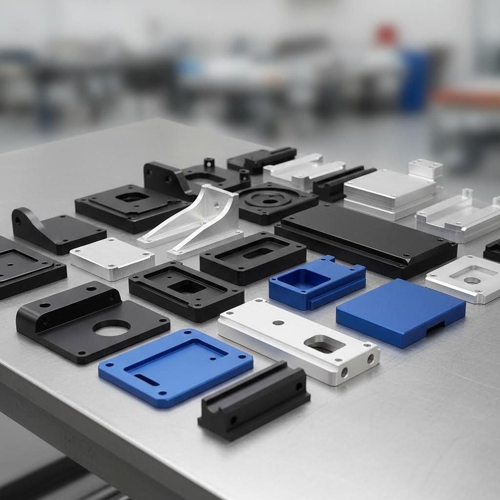
Priemyselné aplikácie pre presné hliníkové diely
Profesionálne výrobné prostredia vyžadujú presné hliníkové diely, ktoré spoľahlivo fungujú za zaťaženia, spĺňajú prísne štandardy kvality a bezproblémovo sa integrujú do väčších zostáv. Podľa Washington Metal Fabricators podniky z viacerých odvetví profitujú z výroby na mieru – od systémov HVAC po poľnohospodársku techniku a ďalšie.
Automobilové komponenty
Automobilový priemysel vo veľkej miere závisí od rezu hliníka na mieru pri výrobe ľahkých komponentov, ktoré zvyšujú palivovú účinnosť bez obeti integrity konštrukcie. Keď potrebujete hliníkový blok na frézovanie motorych konzôl alebo súčastí zavesenia, 6061-T6 zvyčajne ponúka optimálnu rovnováhu pevnosti a obrábania.
- Upevňovacie konzoly a montážne dosky: Laserové rezanie poskytuje požadované presné tolerance pre zarovnanie otvorov na skrutky. Uveďte 6061-T6 pre konštrukčné aplikácie.
- Karosériové panely a konštrukčné zosilnenia: Vodný lúč zachováva tepelné spracovanie komponentov 7075-T6, kde je najvyššia pevnosť rozhodujúca.
- Tepelné clony a kryty: 5052-H32 ponúka vynikajúcu tvárniťasť pre diely, ktoré vyžadujú ohýbanie po rezaní.
Lietajúce a obranné technológie
Keď zlyhanie nie je možné, výrobcovia leteckých strojov určujú najtesnejšie tolerancie a najprísnejšie štandardy kvality. Podľa Protolabs si letecké spoločnosti objednávajú kovové prototypy pri vývoji lietajúcich dronov, mikrosatelitov, planétnych vozidiel, komplexných raketových motorov a nekonečného množstva iných inovácií, ktoré posúvajú hranice techniky.
- Nosné rámy: Rezanie vodným lúčom na doske 7075-T6 – žiadna tepelne ovplyvnená zóna znamená plné udržanie pevnosti.
- Koše pre prístroje: Laserové rezanie 6061-T6 s tesnými toleranciami pre presné prichytenie.
- Prototypové komponenty: CNC frézovanie umožňuje rýchlu iteráciu komplexných 3D geometrií.
Architektonické a stavebné riešenia
Od fasád budov až po dekoratívne interiérové prvky architektonické aplikácie často uprednostňujú estetiku spolu s trvanlivosťou. Vlastné kovové tvary pre architektonické panely bežne používajú zliatinu 5052 pre jej vynikajúcu odolnosť voči korózii a vynikajúce vlastnosti anodizácie.
- Fasádne panely: Laserové rezanie vytvára komplikované vzory z 5052-H32; vodný prúd spracováva hrubšie dekoratívne platne.
- Zábradlia a konštrukčné lišty: profilované výrobky 6061-T6 narezané na dĺžku pílovým rezom, profilové detaily pridané pomocou laseru.
- Propagačné tabule a orientačné systémy: Laserom rezaný 5052 alebo 3003 dokonale prijímajú farbu a práškové nátery.
Elektronika a ochranné skrine
Elektronické skrine chránia citlivé komponenty a zároveň riadia odvod tepla – hliník je vďaka svojej tepelnej vodivosti ideálny. Priemyselné odvetvia vyžadujúce elektrické systémy potrebujú pevné skrine, ktoré zabezpečujú bezpečnosť, prístupnosť a trvanlivosť vo rôznych prostrediach.
- Podvozky a skrine: Laserové rezanie materiálu 5052-H32 pre diely s tvarovanými okrajmi; 6061-T6 pre frézované prvky.
- Odtoky tepla: CNC frézovanie vytvára komplexné vzory lámavín, ktoré maximalizujú povrch.
- Ochrana pred RF: Presné laserové rezanie zabezpečuje tesné závesy, ktoré blokujú elektromagnetické rušenie.
Zaujmové projekty a výroba v malom rozsahu
Na výhody strihu hliníka podľa požiadaviek nemusíte mať rozpočet ako letecký priemysel. Záujmoví výrobcovia, malí výrobcovia a prevádzky zaoberajúce sa prototypovaním majú prístup k rovnakým technológiám za dostupné ceny. Podľa Make It From Metal aj hobby CNC frézky dokážu pri správnom pochopení vlastností materiálu dosiahnuť pôsobivé výsledky pri spracovaní hliníka.
Individuálne nápisy a umenie
Vlastné kovové nápisy patria medzi najobľúbenejšie zaujmové aplikácie pri rezaní hliníka. Trvanlivosť, odolnosť voči poveternostným vplyvom a vizuálny vzhľad materiálu ho robia ideálnym pre všetko – od firemných nápisov až po dekoratívne domáce prvky.
- Tabuľky s adresami a čísla domov: Laserový rez 3003 alebo 5052 – cenovo výhodné a dobre prijímajú farbu.
- Dekoratívne stenové umenie: Krehké dizajny vyniknú vďaka schopnosti laserového rezu vytvárať jemné detaily.
- Firemné značenie: 5052-H32 odoláva vonkajším poveternostným vplyvom; pre vyššiu trvanlivosť odporúčame anodizáciu.
Vytváranie prototypov a vývoj produktov
Inžinieri a vynálezcovia používajú výrobu vlastných hliníkových rezov na overenie návrhov pred zapojením do výrobných nástrojov. Ako uvádza Protolabs, môžete otestovať obrábané hliníkové diely s anodizovaným povrchom a mať istotu, že budú správne fungovať aj pri sériovej výrobe.
- Funkčné prototypy: Použite rovnakú zliatinu a spôsob rezu ako pri výrobe, aby sa výsledky testov presne preniesli.
- Modely na kontrolu prichytenia: Menej kritické tolerancie umožňujú rýchlejšie a hospodárnejšie metódy rezu.
- Malé výrobné série: Laserový alebo vodno-jetový rez eliminuje náklady na nástroje pre množstvá pod 100 kusov.
Projekty pre nadšencov a DIY
Od rámov pre drony po vlastné motocyklové diely – nadšenci využívajú online služby rezu na profesionálnu výrobu bez nutnosti vlastniť drahé zariadenia.
- Komponenty pre lietajúce drony a diaľkovo ovládané vozidlá: Laserovo rezaný hliník 6061-T6 ponúka vynikajúci pomer pevnosti ku hmotnosti.
- Prípravky a upevňovacie zariadenia pre dielne: hliník 6061 alebo 5052 rezaný laserom alebo vodným prúdom – výber podľa zložitosti.
- Špeciálne konzoly a uchytenia: Jednoduché geometrie sa dobre osvedčujú pri plazmovom rezaní za nižšie náklady.
Priradenie aplikácií k metódam rezania: rýchla referenčná tabuľka
Pri rozhodovaní, ako sa pripojiť k vašemu konkrétnemu projektu, zvážte tento rámec, ktorý spája požiadavky aplikácie s optimálnymi možnosťami rezania:
| Typ aplikácie | Odporúčaná zliatina | Najvhodnejšia metóda rezania | Kľúčové úvahy |
|---|---|---|---|
| Štrukturálne komponenty | 6061-T6 alebo 7075-T6 | Vodný prúd (hrubé materiály) / Laser (tenké materiály) | Zachovať tepelné spracovanie; zachovať úzke tolerance |
| Tvárnené diely (vyžaduje ohýbanie) | 5052-H32 | Laser alebo vodný prúd | Tvárniteľnosť je dôležitejšia ako maximálna pevnosť |
| Použitie vonku / v námornej oblasti | 5052-H32 | Laser alebo vodný prúd | Vynikajúca odolnosť voči korózii je nevyhnutná |
| Cenovo citlivá dekoratívna aplikácia | 3003-H14 | Laser | Nákladovo výhodný materiál; dobre prijíma úpravy povrchu |
| Vysokovýrobné prostredie | Závislé od aplikácie | Laser (tenké) / plazma (hrubé) | Rýchlosť a cena za kus určujú výber metódy |
| Iterácia prototypu | Zhoda s výrobným zámerom | Laserové alebo CNC frézovanie | Rýchle dodanie; flexibilita dizajnu |
Pochopenie týchto príslušných aplikácií a metód vám pomôže efektívne komunikovať so spoločníkmi vo výrobe a vyhnúť sa nákladným nesprávnym voľbám. Ale aj dokonalé rezanie necháva hrany neupravené – čo nasleduje ďalej, závisí od vašich požiadaviek na kvalitu hrán a plánov konečného úpravnenia.
Kvalita hrán a možnosti dokončenia
Či už niekedy zdvihli čerstvo odrezaný kus hliníka a cítili ostrú, drsnú hranu, ktorá zachytila váš prst? Nie ste sami. Podľa odborníkov z priemyslu výroby práca rezania nie je dokončená, kým hrany nie sú bezpečné a hladké – a pochopenie toho, čo očakávať od každej rezej metódy, vám pomôže naplánovať úpravy po spracovaní ešte pred doručením dielcov.
Tu je realita: každá rezná technológia zanecháva na hranách hliníka vlastný odtlačok. Niektoré metódy produkujú takmer dokončené povrchy pripravené na montáž, zatiaľ čo iné vyžadujú výrazné upratanie, kým budú vaše súčiastky použiteľné. Pochopenie týchto rozdielov vopred predchádza prekvapeniam a pomáha presne rozpočítať čas a náklady.
Kvalita hrany podľa rezejúcej metódy
Čo sa presne deje na reznej hrane, závisí úplne od toho, ako bol materiál oddelený. Tepelné procesy sa správajú inak ako mechanické a dokonca aj medzi jednotlivými kategóriami existujú významné rozdiely.
Formácia Burra predstavuje najbežnejší problém týkajúci sa kvality hrany. Tieto malé ostré úlomky prichytené na rezaných hranách nie sú len neestetické – vytvárajú bezpečnostné riziká a môžu znemožniť presnú montáž. Rôzne rezné metódy produkujú výrazne odlišné úrovne burinovania:
- Rezanie laserom: Vyrába minimálne zaústenie na tenkom hliníku. Sústredené teplo vytvára mierne preplávanú vrstvu na okraji, ale správnym optimalizovaním nastavení sa dosiahnu okraje dostatočne hladké pre mnohé aplikácie bez sekundárnej úpravy.
- Hydrolakové rezanie: Zanecháva charakteristický texturovaný povrch spôsobený nárazom abrazívnych častíc. Minimálne tepelné vplyvy znamenajú žiadne oxidačné sfarbenie, ale očakávajte mierne drsnosti povrchu, ktoré môžu vyžadovať vyhladenie pri estetických aplikáciách.
- Plazmové rezanie: Spôsobuje najvýraznejšie zaústenie medzi tepelnými metódami. Intenzívne teplo vytvára prichytnutý materiál (znovuztuhnutý kov) na spodnom okraji, ktorý vyžaduje odstránenie brúsením alebo odhrotovaním pred použitím.
- CNC frézovanie: Mechanické rezanie vytvára predvídateľné vzory hrotov – zvyčajne malé hruby na výstupnej strane rezu. Ostré nástroje a vhodné rezné rýchlosti minimalizujú tento efekt.
- Pílové rezanie: Vytvára konzistentné, ale zreteľné hruby, ktoré vyžadujú odstránenie rýhovaním alebo broušením. Drsnosť okraja závisí výrazne od počtu zubov píly a rezačnej rýchlosti.
Zohľadnenie oxidačnej vrstvy je obzvlášť dôležité pri hliníku. Materiál prirodzene tvorí tenkú vrstvu oxidu hliníka do niekoľkých sekúnd po kontakte so vzduchom. Tepelné metódy rezu môžu túto vrstvu narušiť a vytvoriť hrubšie oxidové usadeniny na rezaných hranách – čo môže ovplyvniť následné dokončovacie procesy, ako je zváranie alebo anodizácia.
Porovnanie charakteristík hrán
| Metóda | Typický povrch hrany | Úroveň buriny | Odporúčané následné spracovanie |
|---|---|---|---|
| Laserového rezania | Hladký s miernou preplavenou vrstvou | Minimálne alebo žiadne | Ľahké odhrotovanie v prípade potreby; pripravené na dokončenie |
| Režanie vodným paprskom | Matová textúra, mierne pruhy | Nízke | Broušenie pre estetické aplikácie |
| Plazmové rezanie | Drsný s nánosmi odtoku | Stredné až vysoké | Brúsenie, povinné odhrotovanie |
| Frezovanie CNC | Čistý mechanický rez | Nízke až mierne | Ľahké odstraňovanie hrubín na okrajoch výstupu |
| Pílový rez | Viditeľné stopy nástroja | Mierne | Lisovanie, broušenie pre dokončený vzhľad |
Možnosti dokončenia rezu hliníka
Keď vaše diely dorazia, niekoľko možností úpravy premení surové rezy na profesionálne, bezpečné a trvanlivé povrchy. Voľba závisí od funkčných požiadaviek a estetických očakávaní aplikácie.
Odstraňovanie hrán: Základný prvý krok pre takmer akýkoľvek rez hliníkových dielov. Možnosti sa pohybujú od jednoduchých ručných nástrojov – rýhovníkov, nožov na odstraňovanie hrubín a brúsnych papierov – až po automatizované procesy triedenia pre sériovú výrobu. Ako uvádzajú príručky pre spracovanie, začnite kovovým rýhovníkom alebo nástrojom na odstraňovanie hrubín a prejdite všetky rezné hrany, potom prejdite na jemnejšie zrnenie pre hladšie výsledky.
Anodizácia: Tento elektrochemický proces vytvára trvanlivú, koróziou odolnú oxídovú vrstvu, ktorú možno sfarbiť takmer do akejkoľvek farby. Anódovanie vynikajúco pôsobí na hliník 6061, čím vznikajú konzistentné dekoratívne povrchy. Pre služby práškového nástreku alebo lepenia farieb poskytuje anódovanie vynikajúcu základnú vrstvu.
Práškové náterovanie: Aplikuje hrubú, trvanlivú úpravu, ktorá odoláva lomeniu, škrabaniam a vyblednutiu. Na rozdiel od kvapalnej farby sa práškový náter elektricky viaže na povrchy z hliníka pred tepelným spracovaním. Čistenie a odstránenie hrotov je nevyhnutné – náter sleduje tvar povrchu a môže skôr zviditeľniť ako skryť nedokonalosti okrajov.
Leštenie: Pre aplikácie vyžadujúce vizuálny dopad dodáva leštený hliníkový plech zrkadlový lesk. Postupné brúsenie od 220 cez 400, 600 až po 1000+ zrn vytvára základ, ktorý je následne dokončený pastami na leštenie pre konečný lesk.
Rezanie materiálov s hotovým povrchom
Čo sa stane, keď režete anodizované hárky z hliníku alebo iný materiál s predbežnou úpravou povrchu? Pravidlá sa výrazne menia.
Anodizované povrchy predstavujú jedinečné výzvy. Tvrdá oxidačná vrstva – hoci vynikajúca z hľadiska odolnosti – sa môže pri rezaní odštiepať alebo prasknúť na okrajoch, čím sa odkryje hliníkové jadro náchylnejšie na koróziu. Laserové rezanie zvyčajne poskytuje čistejšie výsledky pri anodizovanom plechu z hliníka než plazmové rezanie, no treba počítať s viditeľným kontrastom medzi anodizovaným povrchom a syrovým rezaným okrajom.
Pri projektoch s predanodizovaným alebo predlakovým materiálom naplánujte doterovanie okrajov alebo prijmite skutočnosť, že rezy budú ukazovať neupravený hliník. Niektorí výrobcovia ponúkajú služby tesnenia okrajov, iní odporúčajú navrhovať diely tak, aby rezy neboli viditeľné na povrchoch.
Po pochopení týchto skutočností týkajúcich sa kvality okrajov a možností dokončenia môžete presne špecifikovať požadované požiadavky – a primerane rozpočtovať celý proces výroby. Keď ste už zohľadnili aspekty dokončenia, ste pripravení vyhodnotiť potenciálnych poskytovateľov rezných služieb, ktorí sú schopní realizovať váš projekt v súlade s týmito štandardmi.
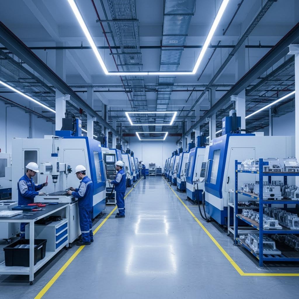
Výber vhodného poskytovateľa rezných služieb
Ovládate výber zliatiny, prispôsobili ste hrúbku materiálu vhodnej reznej metóde, pripravili ste bezchybné návrhové súbory a presne viete, akej kvality okraje sa môžete od vašej výrobky očakávať. Teraz prichádza rozhodnutie, ktoré určuje, či sa všetka táto príprava vyplatí: výber vhodného partnera pre výrobu. Či už hľadáte „kovové spracovanie v mojej blízkosti“ alebo hodnotíte online rezné služby, ako napríklad Oshcut alebo Send Cut Send, kritériá na hodnotenie zostávajú pozoruhodne konzistentné.
Tu je realita: nie všetci výrobcovia sú rovnocenní. Podľa odborníkov z priemyslu, laserové rezanie vyžaduje vysokopresnú prácu, ktorá si vyžaduje špecializované zariadenia, skúsených operátorov a efektívne procesy. Zabezpečenie, že váš vybraný poskytovateľ dokáže dodržať presné špecifikácie, ktoré potrebujete – a to pre prototypovanie, výrobu vlastných komponentov alebo veľkosériovú výrobu – ušetrí čas a peniaze a zabráni drahým chybám.
Predstavte si tento výberový proces ako najímanie dodávateľa na rekonštrukciu domu. Kvalifikácie sú dôležité, ale rovnako dôležitý je štýl komunikácie, reakčná schopnosť a to, či ich kapacity naozaj zodpovedajú požiadavkám vášho projektu. Pozrime sa podrobne, čo presne by ste mali posúdiť.
Vyhodnocovanie kapacít rezania
Predtým ako požiadate o cenové ponuky, musíte pochopiť, či potenciálny partner dokáže váš projekt skutočne realizovať. Niektoré dielne na výrobu kovových konštrukcií v mojej blízkosti sa môžu vyznačovať pri výrobe z ocele, ale nemusia mať skúsenosti s vlastnosťami hliníka. Iné zase môžu perfektne spracovávať tenké plechy, ale majú problémy s hrubými platňami. Položenie správnych otázok na začiatku predchádza strate času a sklamaniam zo výsledkov.
Materiál a rozsah hrúbok: Potvrďte, že poskytovateľ pracuje s vaším konkrétnym zliatinou hliníka vo vyžadovanej hrúbke. Podľa odborníci na výrobu , nie všetky služby rezania sú vybavené na spracovanie širokého spektra materiálov – vláknové lasery s vysokým výkonom dokážu rezať hrubšie a viac odrazivé materiály ako tradičné CO₂ lasery, hoci vhodnosť závisí od mnohých faktorov.
Presné možnosti: Upresnite ich reznú presnosť a schopnosť vytvárať čisté hrany bez hrotov. Vysoce kvalitné služby často ponúkajú úzke tolerancie pre komplikované návrhy. Ak váš projekt vyžaduje ±0,005 palca, overte si, že ich dokážu dodržať trvalo – nie len občas.
Podpora pri návrhu: Hľadajte poskytovateľov, ktorí ponúkajú sprievodné poradenstvo pri navrhovaní výrobkov s ohľadom na výrobné možnosti (DFM). Najlepší partneri skontrolujú vaše súbory pred rezaním a upozornia na potenciálne problémy, ako napríklad príliš malé prvky pre zvolenú metódu alebo špecifikácie tolerancií, ktoré zbytočne zvyšujú náklady. Komplexná podpora DFM mení potenciálne problémy na riešenia ešte predtým, než dôjde k rezaniu kovu.
Kľúčové otázky, ktoré by ste mali položiť potenciálnym dodávateľom
- Aké rezné technológie používate a ktoré odporúčate pre moje konkrétne zliatiny a hrúbku materiálu? Ich odpoveď odhaľuje nielen kapacitu, ale aj odbornosť.
- Aké tolerancie dokážete trvalo dosiahnuť u hliníkových súčiastok podobných mojim? Vyžiadajte si konkrétne informácie, nie všeobecnosti.
- Ponúkate prototypové služby s krátkou dodacou lehotou? Podľa odborných zdrojov umožňuje prototypovanie overiť návrh pred tým, ako sa presuniete na plnoplošnú výrobu – čo je neoceniteľné pri doladení špecifikácií.
- Ako optimalizujete použitie materiálu, aby ste znížili odpad? Poskytovatelia s pokročilým CAD/CAM softvérom dokážu umiestniť viacero návrhov na jeden hárok, čím minimalizujú odpad a maximalizujú výnos.
- Aký je váš bežný čas dodania a ponúkate služby expedovaného spracovania? Služby rýchleho prevedenia môžu byť nevyhnutné pre projekty viazané na čas.
- Ktoré formáty súborov akceptujete a môžete pomôcť s úpravami návrhu? Štandardné formáty zahŕňajú DXF a DWG – niektorí poskytovatelia pracujú tiež s PDF alebo ručne kreslenými náčrtmi.
- Ponúkate ďalšie služby, ako odstraňovanie hrubín, dokončovacie práce alebo montáž? Komplexná služba šetrí koordináciu logistiky.
- Aké máte skúsenosti s projektami podobnými môjmu? Poznanie noriem vo vašom odvetví pomáha predvídať potreby.
Kvalitné certifikácie, ktoré majú význam
Certifikácie nie sú len dekoráciami na stene – znamenajú overené záväzky voči konzistentným procesom kvality. Pre kritické aplikácie, najmä v automobilovom alebo leteckom priemysle, sa stanú konkrétne certifikácie nevyhnutnými požiadavkami.
IATF 16949: Tento špecifický štandard riadenia kvality pre automobilový priemysel ide ďalej ako základný ISO 9001 a obsahuje dodatočné požiadavky týkajúce sa prevencie chýb, zníženia variability a kontinuálneho zlepšovania po celom dodávateľskom reťazci. Pre hliníkové komponenty do automobilov – rámy, uchytenia, konštrukčné zosilnenia – spolupráca so subjektom certifikovaným podľa IATF 16949 zabezpečuje, že vaše diely spĺňajú očakávania priemyslu vo vzťahu ku kvalite.
Napríklad, Shaoyi (Ningbo) Metal Technology ukazuje, čo by výrobcovia automobilov s dôrazom na kvalitu mali ponúkať: výrobu certifikovanú podľa štandardu IATF 16949 pre podvozky a konštrukčné komponenty, spolu s možnosťou rýchleho prototypovania do 5 dní a poskytovaním cenových ponúk do 12 hodín. Táto kombinácia certifikácie, rýchlosti a komplexnej podpory pri návrhu s ohľadom na výrobnosť ilustruje referenčné kritériá pre hodnotenie dodávateľov plechových dielov v blízkosti mňa pre automobilové aplikácie.
ISO 9001: Základný certifikát systému riadenia kvality. Hoci je menej prísny ako IATF 16949, ISO 9001 poukazuje na dokumentované procesy kvality a záväzok neustáleho zlepšovania.
AS9100: Nevyhnutný pre letecké aplikácie. Tento štandard rozširuje ISO 9001 o dodatočné požiadavky špecifické pre letecký, vesmírny a obranný priemysel.
Čas dodania a komunikácia
Rýchlosť má význam – ale predvídateľná rýchlosť má ešte väčší význam. Podľa odborníci na výrobu dlhé dodacie lehoty môžu narušiť výrobné plány, oneskoriť dodávky a zvýšiť náklady, čo vedie k nespokojným zákazníkom a napätým vzťahom.
Rýchlosť reakcie na požiadavku cenovej ponuky: Ako rýchlo potenciálny partner reaguje na požiadavky o cenové ponuky? Táto počiatočná interakcia často predpovedá kvalitu budúcej komunikácie. Poskytovatelia, ktorí zvládnu vypracovanie ponuky do 12 hodín, preukazujú schopnosti aj zameranie na zákazníka.
Výrobné dodacie lehoty: Pochopiť štandardné výrobné časové plány a to, či sú k dispozícii expedované objednávky. Niektorí poskytovatelia dodávajú už za deň alebo dva pri naliehavých úlohách, zatiaľ čo iní vyžadujú týždne. Zoraďte ich možnosti podľa časového harmonogramu vášho projektu.
Prototyp vs. výrobné časy: Služby rýchleho prototypovania – niektoré s termínom dodania 5 dní – umožňujú overenie dizajnu pred zahájením plnej výrobnej série. Táto schopnosť je neoceniteľná pre inžinierske tímy, ktoré iterujú nad dizajnmi.
Získavanie materiálov a flexibilita
Odkiaľ získava váš výrobca hliník? Táto otázka ovplyvňuje konzistenciu kvality aj dodacie lehoty.
Skladom vs. špeciálna objednávka: Poskytovatelia, ktorí udržiavajú bežné zliatiny na sklade (6061-T6, 5052-H32), môžu okamžite začať s rezaním. Špeciálne zliatiny, ako napríklad 7075-T6, môžu vyžadovať dodací čas, ktorý predlžuje časový harmonogram vášho projektu.
Prispôsobivosť veľkosti objednávky: Či už potrebujete jednorazové prototypy alebo vysoké objemy výroby, spoľahlivá služba by mala vyhovieť vašej požadovanej veľkosti objednávky. Podľa odborníkov zabezpečuje táto pružnosť možnosť škálovať objednávky podľa potreby bez nutnosti meniť poskytovateľa – čím sa zachováva konzistencia kvality medzi fázami prototypovania a výroby.
Certifikácia materiálu: Pre kritické aplikácie požiadajte o certifikáty hutní prevádzky, ktoré overujú zloženie zliatiny a jej tepelné spracovanie. Renomovaní výrobcovia oceľových konštrukcií a odborníci na hliník túto dokumentáciu poskytujú bežne.
Výber správnej voľby
Po dokončení vyhodnotenia zvážte svoje zistenia vo vzťahu k priorite projektu. Projekt pre nadšenca môže klásť dôraz na náklady a pohodlie, čo online služby robí atraktívnymi. Výroba automobilových dielov si vyžaduje certifikované procesy kvality a konzistentné tolerancie – čo obmedzuje výber na kvalifikovaných kovodielníkov v blízkosti alebo špecializovaných výrobcov.
Zvážte nadviazanie vzťahu s menšími objednávkami. Testovací projekt odhalí komunikačný štýl, skutočnú (nie sľúbenú) úroveň kvality a to, či spolupráca funguje, ešte predtým, ako sa zaviažete k kritickým výrobným sériám. Dodatočný čas investovaný na začiatku predchádza nákladným prekvapeniam v okamihu najvyšších rizík.
Keď ste si vybrali partnera pre spracovanie kovov, ste pripravení úspešne realizovať váš projekt vlastnej rezania hliníka. Zhrňme všetko do praktickej rozhodovacej schémy, ktorú môžete okamžite použiť.
Rozhodnutie pre vlastné rezanie
Prešli ste si vlastnosti zliatin, úvahy o hrúbke, technológie rezania, prípravu súborov a vyhodnocovanie poskytovateľov. Teraz je čas premeniť tieto poznatky na konkrétne kroky. Či už uvažujete o najlepšom spôsobe rezania hliníkového plechu pre prototyp upínacej lišty alebo plánujete výrobné série presných komponentov, máte rámec na rozhodnutia s istotou.
Tu je kľúčový poznatok: úspešné projekty vlastnej výroby z hliníka nie sú založené na hľadaní jedinej „dokonalé“ odpovede. Ide o to, aby ste svoje špecifické požiadavky – pevnosť, tvárniteľnosť, kvalitu hrany, tolerancie a rozpočet – spojili s vhodnou kombináciou zliatiny, hrúbky a metódy rezania. Tento proces sa stane intuitívnym, ak raz pochopíte, ako tieto premenné spolu súvisia.
Váš kontrolný zoznam pre rozhodovanie o rezaní hliníka na mieru
Pred odoslaním ďalšej objednávky prejdite tento postup, aby sa nič nezmeškalo:
- Najskôr definujte požiadavky vašej aplikácie. Bude diel vyžadovať odolnosť voči namáhaniu? Bude ohýbaný? Bude vystavený vonkajšiemu prostrediu? Vaše odpovede určia voľbu zliatiny – 6061-T6 pre pevnosť, 5052-H32 pre tvárniteľnosť a odolnosť voči korózii, 7075-T6 pre maximálny pomer pevnosti k hmotnosti.
- Uveďte hrúbku v desatinných palcoch. Vyhnite sa zámene čísel kalibrov použitím presných meraní. Overte, že hrúbka hliníkovej dosky zodpovedá zamýšlenému návrhu.
- Prispôsobte spôsob rezu hrúbke materiálu a požiadavkám na tolerancie. Tenké materiály pod 0,125 palca sa vynikajúco hodia na laserové rezanie. Silnejšie platne nad 0,5 palca zvyčajne vyžadujú vodný lúč. Stredné hrúbky ponúkajú najväčšiu flexibilitu – rozhodnutie nech vodiace požiadavky na tolerancie.
- Pripravte čisté a správne formátované konštrukčné súbory. Preveďte text na obrysy, uzavrite všetky kontúry, odstráňte duplicitnú geometriu a jasne uveďte jednotky. Pre najlepšiu kompatibilitu odovzdajte súbory vo formáte STEP alebo DXF.
- Špecifikácie komunikujte jasne a výslovne. Nepredpokladajte, že váš výrobca pozná vaše požiadavky na tolerancie, úpravu okrajov alebo kritické povrchy. Zapíšte si to.
- Plánujte dodatočné spracovanie. Zahrňte odhrotovanie, anodizáciu alebo práškové nástrekovanie do časového plánu a rozpočtu ešte pred zahájením rezu.
- Overte si, či možnosti poskytovateľa zodpovedajú vašim potrebám. Požiadajte o certifikáty materiálu, potvrďte schopnosť dodržiavania tolerancií a vyhodnoťte časy dodania pred tým, ako sa zaviažete.
Pokračovanie vo vašom projekte
Efektívne rezanie hárkového hliníka spočíva v rešpektovaní špecifických vlastností materiálu a súčasnom využití vhodnej technológie pre vašu konkrétnu situáciu. Dôležitý je výber partnера na výrobu, ale rovnako dôležitá je aj jasnosť komunikácie s ním.
Podľa odborníci na výrobu na mieru , jedným z najdôležitejších nástrojov úspešných projektov je komunikácia. Všetko, od najmenších po najväčšie a najkomplexnejšie projekty, začína jasnými cieľmi a dôkladným plánovaním počas počiatočného procesu.
Začnite malo, ak ste nový v oblasti rezania vlastných hliníkových dielov. Prototypová objednávka otestuje váš proces prípravy súborov, overí vaše špecifikácie a odhalí, ako dobre komunikujete s vaším výrobným partnerom – všetko to pred závažnou sériovou výrobou. Táto investícia do učenia sa sa vyplatí pri každom ďalšom projekte.
Teraz máte znalosti potrebné na isté rozhodovanie pri výbere zliatiny, prispôsobenie hrúbky vhodnej metóde rezu, prípravu návrhových súborov profesionálnej úrovne a efektívne hodnotenie výrobných partnerov. Či už spolupracujete s lokálnymi spracovateľmi kovov alebo odosielate objednávky online službám na rezanie, máte teraz nástroje na informované rozhodovanie, ktoré prináša výsledky požadované vašimi projektami.
Najlepší spôsob rezania hliníka nie je jediná metóda – je to metóda, ktorá najlepšie zodpovedá vašej jedinečnej kombinácii požiadaviek. S týmto sprievodcom máte teraz všetko potrebné na nájdenie tej správnej voľby.
Často kladené otázky o rezaní vlastných hliníkových dielov
1. Aká je najlepšia metóda na rezanie vlastného hliníka?
Najvhodnejšia metóda rezu závisí od hrúbky hliníka a požadovaných tolerancií. Laserové rezanie je ideálne pre tenké materiály pod 0,25 palca, pri ktorých dosahuje tolerancie ±0,005 palca s vynikajúcou kvalitou rezaných hrán. Vodným lúčom sa najlepšie reže hrubé platne nad 0,5 palca alebo teplom citlivé zliatiny ako 7075-T6, keďže úplne eliminuje tepelne ovplyvnené zóny. Plazmové rezanie ponúka rýchle a nákladovo efektívne výsledky pre konštrukčné komponenty, kde nie je kritická kvalita rezaných hrán. Pri projektoch vyžadujúcich automobilovú presnosť výrobcovia certifikovaní podľa IATF 16949, ako napríklad Shaoyi Metal Technology, poskytujú komplexnú podporu DFM pri odporúčaní najvhodnejšej metódy pre vaše konkrétne použitie.
2. Koľko stojí rezanie vlastného hliníka?
Náklady na vlastné rezanie hliníka sa líšia v závislosti od hrúbky materiálu, triedy zliatiny, spôsobu rezu, požiadaviek na tolerancie a množstva. Tenké plechy rezané laserom sú zvyčajne lacnejšie na kus kvôli vyššej rýchlosti spracovania. Rezanie hrubej platne vodným lúčom je drahšie kvôli pomalšiemu procesu a spotrebe abrazíva. Špeciálne zliatiny, ako napríklad 7075-T6, sú drahšie ako bežné 6061 alebo 5052. Väčšina služieb ponúka okamžité online cenové ponuky – poskytovatelia s návratnosťou ponuky do 12 hodín vám umožnia rýchlo porovnať možnosti. Objednanie prototypov pred výrobou overí špecifikácie bez nutnosti objednávať veľké množstvá.
3. Aké formáty súborov sú prijímané pre vlastné rezanie kovov?
Profesionálne rezačské služby prijímajú súbory STEP (.stp, .step) ako univerzálny štandard pre výmenu 3D CAD dát. Súbory DXF sú vhodné pre 2D rezné profily na laserových, vodným prúdom a plazmových zariadeniach. Súbory DWG (vlastný formát AutoCAD) a AI (Adobe Illustrator) sa bežne prijímajú pre jednoduchšie návrhy. Pred odoslaním preveďte všetok text na obrysy, uzavrite otvorené kontúry, odstráňte duplicitnú geometriu a overte si svoje jednotky rozmerov. Čistenie a správna príprava súborov zabraňujú oneskoreniam a zabezpečujú presnú generáciu dráhy nástroja pre presné výsledky.
4. Ktorá hliníková zliatina je najlepšia pre výrobu na mieru?
Najlepšia hliníková zliatina závisí od požiadaviek vašej aplikácie. Zliatina 6061-T6 ponúka vynikajúcu obrobitelnosť a pevnosť (45 000 PSI medzipevnosti) pre konštrukčné komponenty a presné diely. Zliatina 5052-H32 ponúka vynikajúcu odolnosť voči korózii a tvárniteľnosť, čo ju robí ideálnou pre námorné aplikácie alebo diely vyžadujúce ohyb po rezaní. Zliatina 7075-T6 ponúka maximálne pomer pevnosti k hmotnosti pre letecké a vysokovýkonné aplikácie, no je drahšia a nie je zvárateľná. Zliatina 3003-H14 ponúka najekonomickejšiu možnosť pre bežné dekoratívne aplikácie, kde stačí stredná pevnosť.
5. Ako nájdem spoľahlivé služby vlastnej kovovej rezby neďaleko mňa?
Vyhodnoťte potenciálnych výrobcov tým, že overíte ich možnosti rezacích technológií, špecifikácie tolerancií a skúsenosti konkrétne s hliníkom. Vyžiadajte si certifikáty materiálov a overte si kvalifikácie v oblasti riadenia kvality – pre automobilové aplikácie je nevyhnutná certifikácia IATF 16949, zatiaľ čo pre letecký priemysel je dôležitá AS9100. Posúďte rýchlosť reakcie na požiadavky a dodacie lehoty; poskytovatelia, ktorí ponúkajú rýchle prototypovanie (dodacia lehota 5 dní) a rýchle cenové ponuky, preukazujú orientáciu na zákazníka. Začnite s malou skúšobnou objednávkou, aby ste ohodnotili kvalitu komunikácie a skutočné výsledky, predtým ako sa zaviažete k sériovej výrobe.