 Pequenas quantidades, altos padrões. Nosso serviço de prototipagem rápida torna a validação mais rápida e fácil —

Os Custos de Estampagem Revelados: Planeje seu Orçamento com Mais Inteligência Antes do Seu Próximo Projeto
O Que É a Estampagem com Matriz e Por Que Ela É Importante na Manufatura
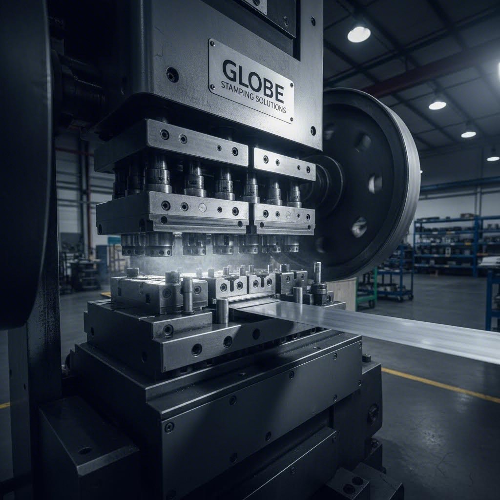
Quando você está planejando um projeto de manufatura que exige peças metálicas de precisão, compreender o que é estampagem torna-se essencial antes de comprometer qualquer orçamento. A estampagem com matriz é um processo de conformação a frio que transforma chapas metálicas planas em componentes acabados usando ferramental especializado denominado matrizes. Ao contrário do corte com matriz em aplicações gráficas — que simplesmente corta papel ou papelão — esta técnica de usinagem de metais molda, dobra e conforma metais em peças tridimensionais complexas a velocidades notáveis.
A estampagem com matriz é um processo de conformação metálica no qual chapas metálicas são moldadas, cortadas ou conformadas mediante sua prensagem entre ferramental especializado (matrizes) montado em prensas, produzindo componentes de precisão para as indústrias automotiva, aeroespacial, eletrônica e de bens de consumo.
Da Chapa Bruta à Peça de Precisão
Imagine uma tira plana de aço entrando em uma prensa e saindo segundos depois como um suporte automotivo perfeitamente formado. Esse é o poder desse processo em ação. A mecânica fundamental é simples: um punção desce para dentro de uma cavidade da matriz, aplicando uma força controlada que deformará plasticamente a peça metálica. Essa força altera a estrutura e a geometria da chapa, permitindo que os fabricantes a dobrem, cortem ou esculpam em praticamente qualquer configuração — desde conectores eletrônicos do tamanho da palma da mão até componentes com até 20 metros quadrados.
Então, o que é uma estampagem, em termos práticos? Trata-se de qualquer peça metálica produzida por meio dessa operação de prensagem. Segundo o IQS Directory, o processo inclui diversos métodos, como corte (blanking), perfuração (punching), punção (piercing) e cunhagem (coining). Cada técnica tem uma finalidade específica, seja para criar furos, cortar formas completas ou adicionar detalhes finos na superfície. A precisão no projeto da matriz é fundamental — cada punção deve garantir resultados consistentes e de alta qualidade ao longo de milhares, ou até mesmo milhões, de ciclos de produção.
A Diferença da Estampagem com Matriz
Compreender o que são matrizes na indústria ajuda a esclarecer por que esse processo predomina na produção em grande volume. As matrizes são ferramentas especializadas, concebidas para criar designs específicos, desde itens cotidianos simples até componentes intrincados em equipamentos eletrônicos. Elas funcionam simultaneamente como instrumentos de corte e como moldes de conformação, capazes de executar múltiplas operações em um único golpe.
A versatilidade da estampagem de metais torna-a indispensável em diversos setores industriais. Fabricantes automotivos contam com ela para painéis de carroceria e componentes estruturais. Empresas aeroespaciais utilizam-na para produzir peças leves e de alta precisão destinadas às estruturas de aeronaves. Fabricantes de equipamentos eletrônicos dependem da estampagem para conectores, terminais e dissipadores de calor. Até mesmo seus eletrodomésticos domésticos contêm dezenas de peças metálicas estampadas que você nunca vê.
O que torna uma matriz de estampagem particularmente valiosa é sua repetibilidade. Uma vez desenvolvida a ferramenta, os fabricantes conseguem produzir peças idênticas, com tolerâncias rigorosas, a velocidades superiores a 1.000 unidades por hora. Essa combinação de precisão, velocidade e eficiência de custos explica por que compreender a economia das matrizes de estampagem é fundamental antes de lançar seu próximo projeto.
Operações Essenciais de Estampagem: de Recorte a Cunhagem
Agora que você compreende os fundamentos, vamos explorar as operações específicas que transformam chapas metálicas brutas em peças acabadas. Todo projeto de estampagem com matriz depende de uma combinação de técnicas de corte e conformação — e conhecer a diferença entre elas impacta diretamente seus custos com ferramental e a qualidade das peças. Considere as operações de corte como aquelas que removem material, enquanto as operações de conformação o remodelam sem retirar qualquer parte.
Operações de Corte Explicadas
As operações de corte utilizam um punção de matriz para separar o material da chapa. A distinção entre esses métodos reside no que se torna seu produto acabado e no que se torna rebarba.
Desbaste recorta formas completas da peça em chapa metálica. A peça expulsa é o seu produto, enquanto o esqueleto remanescente torna-se rebarba. Essa é sua operação preferencial quando você precisa de formas planas iniciais para processamento posterior — pense, por exemplo, em suportes automotivos, contatos elétricos ou painéis de eletrodomésticos. De acordo com Master Products , o recorte (blanking) é extremamente semelhante à perfuração (punching), exceto pelo fato de que as peças perfuradas se tornam o produto acabado.
Punção cria furos precisamente posicionados na sua peça de trabalho usando uma prensa de matriz e uma matriz de corte. Eis a principal diferença: os recortes removidos (slugs) são considerados resíduos, enquanto a sua chapa com os furos é o produto final. Você utilizará o punção para posicionar furos, padrões de ventilação ou pontos de conexão em invólucros e carcaças.
Perfuração funciona quase identicamente ao punção — ambos criam furos —, mas a terminologia utilizada depende frequentemente do contexto industrial. O material removido é denominado slug, e os folgas precisas entre o punção e a matriz determinam a qualidade dos furos. Quando você precisa de dezenas de furos idênticos em caixas de derivação elétrica ou placas de fixação, o processo de perfuração (piercing) oferece resultados consistentes em velocidades produtivas.
Operações de Conformação que Moldam o Metal
As operações de conformação remodelam sua peça de trabalho sem remover material. Essas técnicas exigem uma análise cuidadosa das propriedades do material e do comportamento de recuperação elástica (springback).
Flexão aplica uma força extrema por meio de uma ferramenta de prensagem para dobrar metal em ângulos específicos. De acordo com a Fictiv, os engenheiros devem levar em conta o retorno elástico — a tendência do material de voltar parcialmente à sua forma original — projetando a matriz para dobrar excessivamente a peça . Isso é essencial para produzir componentes em forma de V ou de U, como suportes, perfis em canal e estruturas de invólucros.
Desenho cria características ocas, em forma de copo ou rebaixadas forçando a chapa metálica para dentro de uma cavidade da matriz. O punção empurra o material para baixo na cavidade da matriz, esticando-o e moldando-o ao redor das paredes dessa cavidade. A conformação profunda — utilizada em recipientes sem costura, tanques de combustível automotivos e utensílios de cozinha — exige múltiplas etapas de conformação para evitar rasgos ou enrugamentos.
Reboque estampa apenas um lado da peça para criar padrões salientes ou reentrantes sem cortar completamente o material. Características comumente em relevo incluem números, letras, logotipos ou desenhos decorativos em painéis de eletrodomésticos e placas de sinalização.
Cunhagem leva a estampagem em relevo ainda mais longe, comprimindo o metal simultaneamente em ambos os lados. O processo de cunhagem aplica uma pressão imensa para criar detalhes extremamente finos com precisão dimensional superior. Este exemplo de estampagem é como moedas, medalhas comemorativas e componentes de hardware de precisão com logotipos recebem suas intrincadas características superficiais.
| Operação | Finalidade | Aplicações típicas | Intervalo de Espessura do Material |
|---|---|---|---|
| Desbaste | Recortar formas completas de chapas | Suportes, contatos elétricos, componentes planos | 0,005" – 0,25" |
| Punção | Criar furos na peça trabalhada | Furos de ventilação, pontos de fixação, furos de conexão | 0,005" – 0,25" |
| Perfuração | Criar furos de precisão (o material removido é considerado sucata) | Furos de posicionamento, saídas elétricas | 0,005" – 0,20" |
| Flexão | Dobrar o metal em ângulos específicos | Suportes, canais, estruturas de invólucros | 0,010" - 0,25" |
| Desenho | Criar peças ocas ou em forma de copo | Recipientes, tanques de combustível, utensílios de cozinha, invólucros | 0,010" – 0,20" |
| Reboque | Criar padrões salientes ou rebaixados | Logotipos, inscrições, painéis decorativos | 0,010" - 0,125" |
| Cunhagem | Comprimir metal para obter detalhes finos na superfície | Moedas, medalhas, componentes mecânicos de precisão | 0,005" – 0,10" |
Compreender essas operações ajuda-o a comunicar-se eficazmente com o seu fornecedor de estampagem. A maioria das peças produzidas combina várias técnicas — por exemplo, um suporte pode exigir corte para definir o contorno, perfuração para os furos de fixação e dobramento para formar sua geometria final. Quanto maior o número de operações exigidas pela sua peça, mais complexa se torna a ferramenta de corte por matriz, afetando diretamente o orçamento do seu projeto. Com estes conceitos fundamentais consolidados, você está pronto para explorar como diferentes configurações de matrizes — progressivas, de transferência e compostas — executam essas operações em escala produtiva.
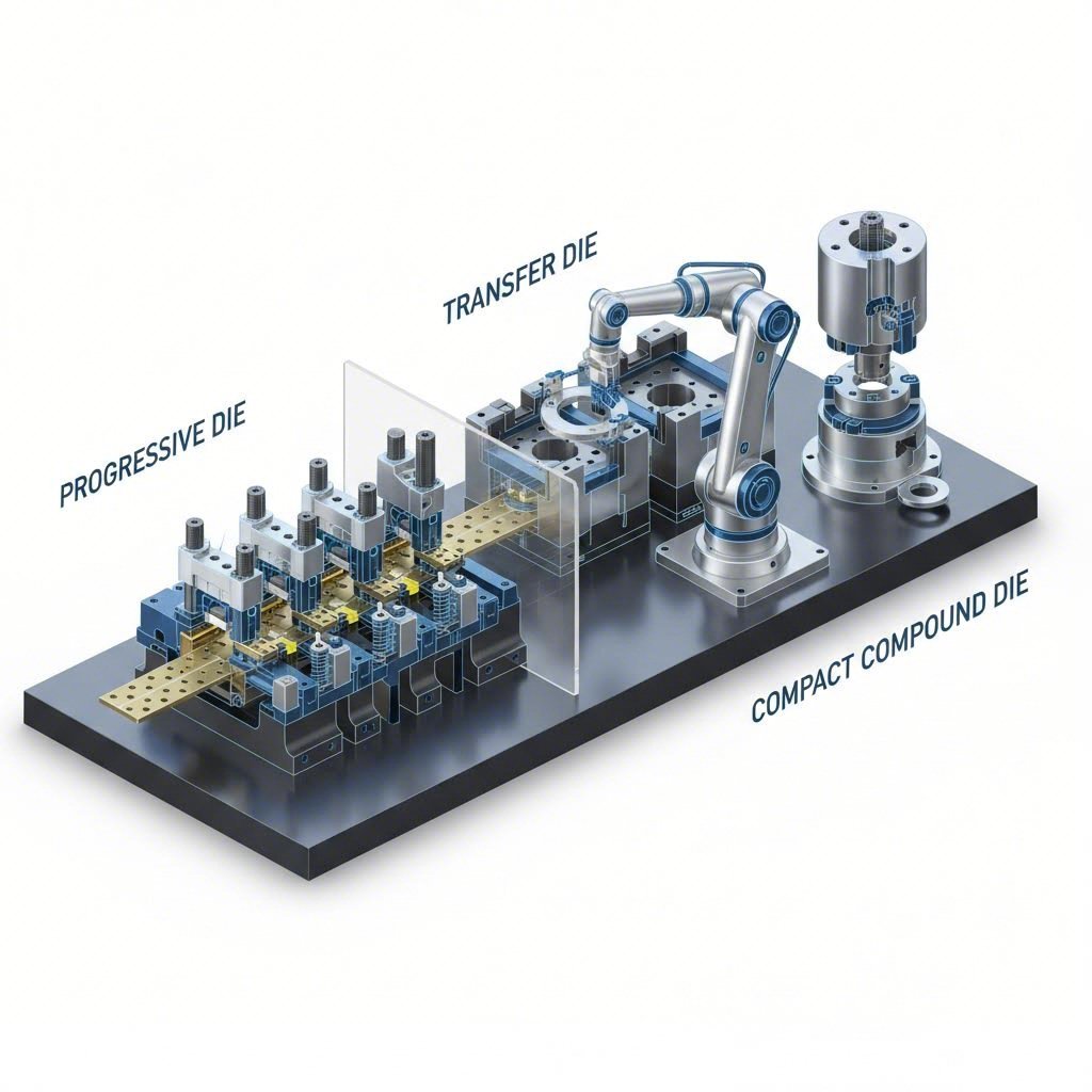
Estampagem progressiva versus estampagem por transferência versus estampagem com matriz composta
Você já aprendeu as operações individuais — corte, perfuração, dobramento e embutimento. Mas é aqui que o planejamento orçamentário se torna interessante: a forma como essas operações são configuradas dentro da sua matriz afeta drasticamente seu investimento em ferramental e os custos por peça. Escolher entre estampagem progressiva, estampagem por transferência e estampagem composta não é apenas uma decisão técnica — é uma decisão financeira que pode determinar o sucesso ou o fracasso da viabilidade econômica do seu projeto.
Pense nisso desta forma: os três métodos utilizam as mesmas operações fundamentais, mas as organizam de maneira distinta com base na complexidade, dimensão e volume de produção da sua peça. Vamos analisar cada abordagem para que você consiga associar a configuração de matriz adequada às suas necessidades específicas.
Matrizes Progressivas para Alta Eficiência em Produção
A estampagem progressiva é a cavalo de batalha da fabricação em grande volume no processo de estampagem em matriz progressiva, uma tira contínua de metal é alimentada através de uma única matriz contendo múltiplas estações dispostas em sequência. Cada estação executa uma operação específica — perfuração, dobramento, conformação ou corte — à medida que a tira avança a cada golpe da prensa. A peça permanece presa à tira portadora do início ao fim, sendo separada apenas como peça finalizada na estação final.
Imagine produzir componentes automotivos no estilo de estampagem progressiva: uma bobina de aço entra por uma extremidade, e suportes, grampos ou conectores acabados saem pela outra extremidade a taxas superiores a 1.000 peças por hora. Esse fluxo contínuo elimina a manipulação entre operações, reduzindo drasticamente os custos com mão de obra e os tempos de ciclo.
Segundo a Larson Tool, as matrizes progressivas exigem custos mais elevados de projeto e ferramental iniciais devido à sua natureza complexa e aos requisitos de engenharia de precisão. No entanto, o custo por peça diminui significativamente em grandes séries de produção, tornando essa abordagem altamente econômica para projetos de longo prazo.
- Alta eficiência: Múltiplas operações ocorrem simultaneamente em estações distintas, maximizando a produtividade
- Redução dos resíduos: Layouts otimizados da tira minimizam os resíduos de material
- Redução de Custos com Mão de Obra: A alimentação automatizada elimina a manipulação manual das peças entre as operações
- Tolerâncias rigorosas: As peças permanecem registradas na tira durante todo o processo, garantindo consistência
- Geometrias Complexas: Estações sequenciais podem produzir formas intrincadas impossíveis de obter em uma única operação
Principais Aplicações: Peças de pequeno a médio porte (componentes do tamanho da palma da mão são ideais), volumes elevados de produção superiores a 10.000 unidades e peças que exigem múltiplas operações de conformação e corte. As matrizes progressivas destacam-se na produção de conectores elétricos, suportes, grampos e componentes terminais.
Matrizes de Transferência para Geometrias Complexas
O que acontece quando sua peça é muito grande para a estampagem progressiva ou requer uma conformação profunda que não pode ocorrer enquanto estiver presa à tira portadora? É nesse momento que entra em cena a estampagem por matriz de transferência.
A estampagem por transferência separa a peça-bruta da tira metálica no início do processo. Dedos mecânicos, robôs ou outros mecanismos automatizados de transferência movem, então, cada peça individual entre estações de matriz distintas. Essa independência permite operações impossíveis em configurações progressivas — como conformações profundas, conformação extensiva e trabalho em todas as superfícies da peça.
Segundo a Keats Manufacturing, o processo em múltiplas etapas da estampagem por matriz de transferência permite designs com alto grau de complexidade, incluindo roscas, nervuras e estrias. Como a remoção da tira metálica ocorre no início, as matrizes de transferência são ideais para peças conformadas profundamente e para aplicações que exigem manipulação extensiva da peça-bruta.
- Lida com peças grandes: Componentes que abrangem várias centenas de metros quadrados podem se mover entre estações dedicadas
- Capacidade de embutimento profundo: As peças podem ser extraídas sem as restrições da tira portadora
- acesso em 360 graus: As operações podem ser realizadas em todas as superfícies, pois as peças não estão fixadas às tiras
- Redução de operações secundárias: Rosqueamento, estriamento e recursos especializados são integrados ao processo de estampagem
- Volumes de produção versáteis: Economicamente viável para lotes médios a altos, nos quais a complexidade justifica o investimento em ferramental
Principais Aplicações: Componentes estruturais grandes, carcaças e invólucros profundamente estampados, peças que exigem recursos em múltiplas superfícies e componentes de até 20 metros quadrados. As matrizes de transferência destacam-se em peças estruturais aeroespaciais, painéis de carroceria automotiva e componentes de máquinas pesadas.
Matrizes Compostas para Cortes de Precisão
Às vezes, a simplicidade vence. A estampagem com matriz composta realiza múltiplas operações de corte — recorte, perfuração e punção — em um único golpe de prensa. Em vez de avançar por estações sequenciais, toda a operação ocorre de uma só vez dentro de um único conjunto de matrizes.
Segundo a Keats Manufacturing, a estampagem com matriz composta é ideal para produzir peças planas, como arruelas e discos de rodas, em volumes médios ou altos. A operação simultânea gera peças mais planas do que os métodos progressivos, pois forças iguais atuam sobre a peça a partir de ambos os lados.
Eis a compensação: as matrizes compostas executam excelentemente operações de corte, mas não são projetadas para conformação. Se sua peça exigir dobramento, embutimento ou modelagem, será necessário recorrer a métodos progressivos ou por transferência — ou a operações secundárias após a estampagem com matriz composta.
- Custos Mais Baixos de Ferramental: A construção mais simples da matriz reduz o investimento inicial em comparação com as matrizes progressivas
- Planicidade superior: O corte simultâneo a partir de ambos os lados produz peças mais planas
- Alta repetibilidade: A operação em um único golpe garante resultados consistentes
- Produção Rápida: Peças planas simples saem rapidamente com tempo de ciclo mínimo
- Manutenção reduzida: Uma estrutura mais simples significa menos componentes que exigem manutenção
Principais Aplicações: Peças planas sem requisitos de conformação — arruelas, juntas, chapas cortadas para processamento posterior, laminados elétricos e placas de montagem simples. Matrizes compostas oferecem excelente relação custo-benefício para volumes médios a altos de componentes geometricamente simples.
Fazendo sua Escolha: Um Quadro Decisório
Escolher entre essas três abordagens resume-se à avaliação do seu projeto com base em três critérios: complexidade da peça, volume de produção e restrições orçamentárias.
Escolha a estampagem progressiva quando: Você precisa de volumes elevados (geralmente 10.000 peças ou mais), sua peça é de tamanho pequeno a médio e exige múltiplas operações, incluindo conformação. O investimento maior em ferramental compensa-se por custos por peça drasticamente menores em escala.
Escolha matrizes de transferência quando: Suas peças são grandes, exigem estampagem profunda ou necessitam de operações em múltiplas superfícies. As matrizes de transferência justificam seus custos mais elevados de ferramental e de preparação graças à sua capacidade — elas realizam trabalhos que matrizes progressivas simplesmente não conseguem.
Escolha matrizes compostas quando: Você está produzindo peças planas com operações de corte apenas, deseja custos iniciais mais baixos de ferramental ou precisa de peças com planicidade superior. As matrizes compostas oferecem o melhor custo-benefício para geometrias mais simples, em volumes moderados a altos.
Compreender essas distinções posiciona você para manter conversas informadas com fornecedores potenciais sobre a seleção de materiais — o próximo fator crítico que influencia tanto os requisitos de projeto da matriz quanto o resultado financeiro do seu projeto.
Critérios de Seleção de Materiais para Projetos de Estampagem com Matriz
Você selecionou sua configuração de matriz — progressiva, por transferência ou composta. Agora chega uma decisão que impacta diretamente tanto seus custos com ferramental quanto o desempenho da peça: qual material você deve estampar? A escolha errada não afeta apenas seu produto acabado; ela pode complicar o projeto das matrizes para chapas metálicas, aumentar os requisitos de tonelagem da prensa e introduzir problemas de qualidade que se propagam por toda a sua produção.
O sucesso na estampagem e conformação de metais começa com o alinhamento das propriedades do material às exigências da sua aplicação. Vamos analisar os principais critérios que devem orientar sua seleção e, em seguida, examinar como cada material comum se comporta nesse contexto.
Associar Materiais aos Requisitos de Desempenho
Antes de comparar metais específicos, considere o que sua aplicação realmente exige. De acordo com a PANS CNC, a seleção do material adequado para estampagem é fundamental não apenas para atender aos requisitos de uso final, mas também para controlar o próprio processo de estampagem. Variáveis como espessura da chapa, tensão de dobramento e força de estampagem são todas influenciadas pelo tipo de material.
Pergunte a si mesmo estas perguntas:
- A quais condições ambientais a peça estará exposta? Atmosferas corrosivas, altas temperaturas ou exposição ao ar livre exigem propriedades específicas do material.
- Quais cargas mecânicas a peça deve suportar? A resistência à tração e a resistência à fadiga variam drasticamente entre os materiais.
- Qual é a complexidade da geometria da sua peça? Dobras intrincadas e estampagens profundas exigem materiais com excelente conformabilidade.
- Qual é sua tolerância orçamentária? Os custos dos materiais podem variar de 0,50 dólar por libra para aço carbono a mais de 15 dólares por libra para titânio.
A espessura do material afeta diretamente o projeto da sua matriz e os requisitos da prensa. Materiais mais espessos exigem maior tonelagem da prensa, ferramentas mais robustas e, muitas vezes, folgas maiores entre o punção e a matriz. Uma chapa de aço inoxidável de 0,060" requer significativamente mais força para conformação do que uma chapa de alumínio de 0,030" do mesmo tamanho — chegando, às vezes, a dobrar ou triplicar a tonelagem necessária.
Aço, Alumínio e Além
Vamos analisar os materiais mais comuns para estampagem de chapas metálicas e as aplicações em que cada um se destaca.
Aço de baixo carbono oferece o melhor custo-benefício para aplicações gerais. Segundo a PANS CNC, o aço de baixo teor de carbono contém aproximadamente 0,05% a 0,3% de carbono, proporcionando boa soldabilidade, ductilidade e resistência à tração a um custo reduzido. Graus comuns, como os 1008, 1010 e 1018, são facilmente estampáveis, mas exigem revestimentos protetores em ambientes corrosivos.
Aço Inoxidável oferece resistência superior à corrosão e um acabamento atraente. As ligas austeníticas da série 300 (301, 302, 316) oferecem excelente ductilidade, mas apresentam taxas mais elevadas de encruamento — ou seja, tornam-se mais duras e frágeis à medida que são estampadas. Segundo a Ulbrich, o aço inoxidável austenítico pode sofrer transformação durante a deformação, induzindo uma fase martensítica frágil que aumenta o risco de trincas. Isso exige um projeto cuidadoso de matrizes e, possivelmente, recozimento intermediário para peças complexas.
Alumínio destaca-se onde o peso é crítico. O processo de estampagem de alumínio produz peças 65 % mais leves do que as equivalentes em aço, com excelente resistência à corrosão e condutividade térmica. No entanto, o alumínio apresenta um desafio significativo: o retorno elástico (springback). Segundo a O Fabricante ligas de alumínio de alta resistência revolucionaram práticas consolidadas de décadas sobre o retorno elástico, exigindo ensaios de tração-compressão e simulações sofisticadas para prever com precisão o comportamento do material. Suas matrizes para chapas metálicas devem compensar esse efeito por meio de uma curvatura excessiva do material, antecipando a quantidade de retorno elástico após a conformação.
De cobre e latão destacam-se em aplicações elétricas e decorativas. A elevada condutividade do cobre torna-o essencial para componentes de potência, enquanto o latão oferece um aspecto atrativo aliado à excelente conformabilidade para dobras complexas. Ambos os materiais sofrem encruamento durante a estampagem, portanto, a seleção da liga deve ser feita com cuidado em operações de múltiplos estágios.
| Material | Formabilidade | Resistência | Resistência à corrosão | Custo Relativo | Aplicações típicas |
|---|---|---|---|---|---|
| Aço de baixo carbono | Excelente | Moderado | Ruim (precisa de revestimento) | $ | Suportes, invólucros, painéis automotivos |
| Aço inoxidável (série 300) | Boa | Alto | Excelente | $$$ | Equipamentos para alimentos, dispositivos médicos, eletrodomésticos |
| Aço Inoxidável (série 400) | Boa | Alto | Boa | $$ | Acabamentos automotivos, ferragens industriais |
| Alumínio (5052, 6061) | Muito bom | Moderado | Muito bom | $$ | Componentes aeroespaciais, carcaças para eletrônicos |
| Cobre (C110) | Excelente | Baixa-Moderada | Boa | $$$ | Contatos elétricos, barramentos, terminais |
| Brasão (C26000) | Excelente | Moderado | Boa | $$ | Ferragens decorativas, conectores elétricos |
A orientação do grão é mais importante do que muitos engenheiros percebem. Quando a chapa metálica estampada é laminada na usina, a estrutura cristalina se alinha na direção da laminação. Dobrar paralelamente a essa direção de grão exige maior força e pode causar trincas, enquanto dobrar perpendicularmente produz resultados mais suaves. Especifique os requisitos quanto à direção do grão nos seus desenhos sempre que a geometria da peça exigir dobras críticas — especialmente para aço inoxidável e ligas de alta resistência.
Ao adquirir materiais, verifique se o seu fornecedor fornece relatórios certificados de ensaio de usina que documentem as propriedades mecânicas, a composição química e o tamanho do grão. A consistência do material de bobina para bobina evita variações de qualidade que comprometem as séries de produção. Segundo a Ulbrich, estabelecer parceria com uma usina de rerrolagem de precisão dotada de expertise metalúrgica pode ser extremamente útil para estampadores na realização de análises de causa-raiz quando surgem problemas.
Com seu material selecionado, a próxima etapa crítica envolve compreender como o projeto e a engenharia de matrizes transformam sua escolha de material em ferramentas prontas para produção — onde as tolerâncias de precisão e a seleção de componentes determinam se suas peças atendem às especificações.
Projeto e Engenharia de Matrizes e Fundamentos de Componentes
Você já escolheu seu material e a configuração da matriz. Agora começa a fase de engenharia que distingue projetos bem-sucedidos de falhas onerosas: o projeto das próprias matrizes que produzirão suas peças. É nesse momento que a precisão encontra a praticidade — onde cada decisão relativa a folgas, componentes e tolerâncias afeta diretamente se sua produção atende às especificações ou gera refugos.
Parece complexo? É mesmo. No entanto, compreender os fundamentos ajuda você a avaliar as capacidades dos fornecedores, formular perguntas mais pertinentes e identificar quando atalhos de engenharia podem comprometer seu projeto. Vamos analisar como o projeto moderno de matrizes transforma seu conceito de peça em ferramentas prontas para produção.
Precisão de Engenharia em Cada Matriz
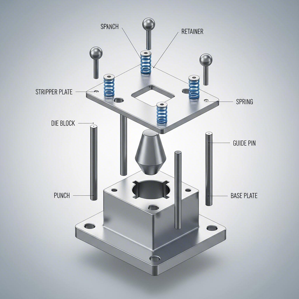
Uma matriz para operações de prensagem é muito mais do que um simples punção e uma cavidade. Segundo a U-Need Precision Manufacturing, uma matriz de estampagem bem-sucedida é o resultado de um processo estruturado e multietapas de projeto, no qual cada etapa se baseia na anterior, avançando desde o conceito geral até planos de engenharia detalhados e validados.
Toda ferramenta de matriz de estampagem contém estes componentes críticos trabalhando em conjunto:
- Punção: O componente macho que desce para dentro da cavidade da matriz, realizando operações de corte ou conformação. Os punções devem suportar forças compressivas enormes — um punção de 1/2" de diâmetro perfurando aço doce com espessura de 0,062" exige aproximadamente 2,5 toneladas de pressão.
- Bloco de morte: O componente fêmea que contém a cavidade ou abertura que recebe o punção. As superfícies endurecidas do bloco da matriz definem a geometria final da peça e devem manter dimensões precisas ao longo de milhões de ciclos.
- Placa desbobinadora: Mantém a chapa metálica plana contra a superfície da matriz e retira o material do punção após cada golpe. Sem uma ação adequada de desprendimento, as peças aderem aos punções e causam entupimentos.
- Pinças-guia e Buchas: Componentes de alinhamento de precisão que garantem que o punção entre na cavidade da matriz exatamente na mesma posição em cada golpe. Até mesmo um desalinhamento de 0,001" pode causar desgaste irregular e problemas dimensionais.
- Fontes: Fornecem pressão controlada para desprendimento, retenção da chapa e funções de almofada da matriz. A seleção das molas afeta a qualidade da conformação, a ejeção das peças e o desempenho geral da matriz.
A interação desses componentes da prensa e da matriz é o que os engenheiros de manufatura chamam de 'ballet mecânico' — cada elemento sincronizado em frações de segundo pelo ciclo da prensa. Ao trabalhar com uma ferramenta de matriz, compreender essa interação ajuda você a perceber por que a manufatura de precisão é tão importante.
Considerações sobre Tolerâncias e Folgas da Matriz
Aqui está um conceito crítico que afeta diretamente a qualidade de suas peças: folga da matriz. Trata-se do espaço entre o punção e a abertura da matriz, normalmente especificado como uma porcentagem da espessura do material por lado.
Segundo o guia de projeto da Larson Tool, as folgas de corte entre punção e matriz são rigorosamente definidas — normalmente cerca de 8% a 10% da espessura do material por lado. Essa folga gera uma condição previsível na borda: inicialmente, o punção comprime o material, produzindo uma borda superior arredondada. À medida que o corte começa, ele cisalha o material em aproximadamente 1/4 a 1/3 da espessura, deixando uma parede polida (burnished wall). Por fim, o material cede e se separa, deixando uma leve rebarba na borda inferior.
Por que isso importa para seu orçamento? Porque os requisitos de tolerância determinam a complexidade da matriz:
- Tolerâncias dimensionais de ±0,002" são alcançáveis na maioria das aplicações de corte e perfuração
- A localização furo-a-furo normalmente é mantida dentro de ±0,002" quando os furos são perfurados na mesma operação
- Características que exigem tolerâncias mais rigorosas podem necessitar de operações secundárias de acabamento ou calibragem
- Características conformadas introduzem variáveis adicionais — tolerâncias angulares de ±1 grau são padrão para dobras
Ranhuras de desvio em matrizes de estampagem de chapas metálicas merecem menção especial. Trata-se de cortes de alívio posicionados em locais críticos para evitar que o material fique preso durante operações progressivas. Quando uma tira avança por múltiplas estações, as ranhuras de desvio permitem que características previamente conformadas passem pelas superfícies da matriz sem interferência. Sem o posicionamento adequado dessas ranhuras, seções conformadas podem travar contra estações subsequentes, causando danos à matriz e paralisações na produção.
Do CAD à ferramenta pronta para produção
O projeto moderno de matrizes de estampagem baseia-se fortemente em ferramentas digitais que encurtam os prazos de desenvolvimento e reduzem a necessidade de testes e erros dispendiosos. Veja como ocorre tipicamente o fluxo de trabalho de projeto à produção:
- Análise do desenho da peça: Engenheiros avaliam a geometria da sua peça quanto à estampabilidade — identificando possíveis problemas com raios de curvatura, profundidades de estampagem ou espaçamento entre recursos antes mesmo de qualquer trabalho de projeto começar.
- Desenvolvimento do Layout da Tira: Para matrizes progressivas, esta etapa crítica organiza todas as operações de corte e conformação em sequência ótima. Segundo a U-Need, o layout da tira é um processo iterativo que minimiza o desperdício de material ao mesmo tempo que maximiza a velocidade de produção.
- modelagem 3D por CAD: Usando softwares como SolidWorks ou CATIA, os engenheiros criam modelos detalhados de todos os componentes da matriz — punções, blocos matriz, extratores e sistemas de guia — todos dimensionados e com tolerâncias definidas para fabricação.
- Simulação por CAE: É aqui que a tecnologia moderna reduz drasticamente os riscos. Usando plataformas como AutoForm ou DYNAFORM, os engenheiros simulam digitalmente todo o processo de estampagem antes mesmo de cortar qualquer aço para ferramental.
- Programação por CAM: Os projetos validados são convertidos em instruções de usinagem para equipamentos CNC, eletroerosão por fio (wire EDM) e operações de retificação.
- Validação de Protótipo: As peças da primeira série passam por inspeção dimensional e testes funcionais antes da aprovação para produção.
A fase de simulação por CAE merece atenção especial, pois é nela que defeitos potenciais são identificados antes de se tornarem problemas onerosos. Segundo a U-Need, o software de simulação permite aos projetistas modelar o comportamento do material sob condições de conformação — prevendo onde a chapa se esticará excessivamente, sofrerá flambagem, enrugará ou trincará. Esse processo de validação virtual possibilita iterações rápidas; ajustar um modelo digital é muito mais barato e rápido do que refresar ferramentas em aço temperado.
As capacidades de simulação incluem:
- Previsão do comportamento de retorno elástico (springback) e compensação correspondente da geometria da matriz
- Identificação de áreas propensas ao afinamento, enrugamento ou fissuração
- Otimização da forma e da posição da chapinha (blank) para eficiência no uso do material
- Validação do posicionamento das nervuras de tração (draw beads) e dos parâmetros de pressão do segurador de chapinha (blank holder)
- Confirmação de que as dimensões finais da peça estão dentro das especificações
Esse fluxo digital — desde o conceito inicial até os programas validados de CAM — cria o que os engenheiros chamam de cadeia de projeto à produção. Quando as matrizes são fabricadas a partir de projetos minuciosamente simulados, as taxas de aprovação do primeiro artigo aumentam significativamente e o tempo de ajuste diminui de semanas para dias.
Compreender esses fundamentos de engenharia posiciona você para avaliar potenciais fornecedores de forma eficaz. Pergunte sobre suas capacidades de simulação, processos de validação de projeto e taxas de sucesso na primeira tentativa. Um parceiro com práticas robustas de engenharia fornece ferramental que opera corretamente desde a primeira vez — poupando-lhe os excessos orçamentários que assolam projetos nos quais as matrizes exigem múltiplos ciclos de correção. Com os princípios de projeto estabelecidos, a próxima consideração crítica é manter a qualidade das peças ao longo da produção e garantir que suas matrizes operem com eficiência máxima.
Práticas Recomendadas de Controle de Qualidade e Manutenção de Matrizes
O seu projeto de matriz é impecável. A sua seleção de materiais é perfeita. Mas aqui vai uma realidade: mesmo as melhores matrizes de estampagem se degradam com o tempo, e problemas de qualidade acabarão por surgir na sua produção. A diferença entre operações lucrativas e taxas elevadas de refugos resume-se a um único fator: a rapidez com que identifica os defeitos e a sistematicidade com que realiza a manutenção das suas ferramentas.
Imagine as suas matrizes de estampagem como atletas de alto desempenho. Elas necessitam de condicionamento regular, de uma nutrição adequada (lubrificação) e de atenção imediata sempre que ocorrem lesões. Ignorar esses princípios fundamentais fará com que até as matrizes de estampagem em aço mais sofisticadas apresentem desempenho aquém do esperado. Vamos elaborar o seu manual prático de resolução de problemas e a sua estratégia de manutenção.
Identificando Defeitos Comuns Antes Que Se Multipliquem
Cada peça defeituosa que sai da sua prensa está lhe enviando uma mensagem. De acordo com Jeelix , as peças estampadas estão longe de ser simples sucata — são os correspondentes de guerra mais fiéis do estado de seu molde. Aprender a interpretar esses sinais distingue a gestão reativa de crises da gestão proativa de qualidade.
Os cinco defeitos mais comuns nas operações de estampagem por matriz apontam cada um para causas-raiz específicas. Ao identificar um desses problemas, não se limite a corrigir o sintoma — rastreie-o até sua origem e resolva o problema subjacente.
| Defeito | Sintomas | Causas comuns | Ações Corretivas |
|---|---|---|---|
| Rebarbas | Bordas elevadas, saliências afiadas nas superfícies cortadas | Folga excessiva entre punção e matriz, bordas de corte desgastadas, ferramentas embotadas | Afiar ou substituir punção/matriz, reduzir a folga, verificar o alinhamento |
| Rugas | Superfícies onduladas, acúmulo de material nas áreas de rebordo | Força insuficiente do segurador de chapas, fluxo excessivo de material, projeto inadequado de cordões de tração | Aumentar a pressão do segurador de chapas, adicionar ou modificar cordões de tração, ajustar a lubrificação |
| Trincas/Rupturas | Rachaduras no material, fraturas nos raios de dobramento ou nas paredes de estampagem | Força excessiva do segurador da chapa, raios da matriz insuficientes, lubrificação inadequada, defeitos no material | Reduzir a pressão do segurador da chapa, aumentar os raios da matriz/punção, melhorar a lubrificação, verificar as especificações do material |
| Retorno elástico | Peças fora da especificação angular após a conformação | Recuperação elástica do material, compensação insuficiente de sobredobramento, pressão de cunhagem inadequada | Aumentar o ângulo de sobredobramento, aplicar cunhagem nas áreas de dobramento, utilizar técnicas de pós-estiramento |
| Variação dimensional | Peças fora dos limites de tolerância, medições inconsistentes | Desgaste da matriz, expansão térmica, deformação da prensa, variação na espessura do material | Recalibrar as matrizes, verificar a consistência do material, ajustar as configurações da prensa, implementar monitoramento por Controle Estatístico de Processo (CEP) |
Segundo a Jeelix, a relação entre a força do segurador da chapa, os raios da matriz e a lubrificação forma um triângulo crítico que rege todas as operações de estampagem profunda. Restrição excessiva causa rasgos; restrição insuficiente causa enrugamentos. Sua matriz para chapas metálicas deve equilibrar com precisão essas forças concorrentes.
Análise da Causa-Raiz de Problemas em Estampagem
Quando aparecem defeitos, resista à tentação de ajustar aleatoriamente os parâmetros da prensa. Em vez disso, siga uma abordagem diagnóstica sistemática que examine tanto as peças estampadas quanto as próprias matrizes.
Técnicas de Inspeção em Processo
O monitoramento contínuo detecta problemas antes que eles se multipliquem em séries dispendiosas de refugos. Segundo a Acro Metal, a inspeção em processo envolve verificações regulares das dimensões das peças, do acabamento superficial e da qualidade geral. Sistemas automatizados, sensores e câmeras podem avaliar a conformidade das peças e identificar desvios em relação aos padrões estabelecidos em tempo real.
Métodos eficazes de inspeção incluem:
- Inspeção da primeira peça: Verificar a precisão dimensional antes de iniciar séries de produção
- Amostragem periódica: Verificar peças em intervalos regulares ao longo da série
- Inspeção visual da superfície: Identificar arranhões, marcas de galling ou imperfeições superficiais
- Medição com calibre passa/não-passa: Verificação rápida de dimensões críticas utilizando calibradores fixos
- Medição CMM: As máquinas de medição por coordenadas fornecem dados dimensionais abrangentes para peças complexas
Controle Estatístico de Processos (SPC)
Segundo a Acro Metal, o controle estatístico de processo (CEP) é um método utilizado para monitorar e controlar a consistência do processo de estampagem. Por meio da coleta e análise de dados em várias etapas, os fabricantes podem identificar tendências, variações ou anomalias no processo produtivo. Gráficos de controle que acompanham dimensões críticas revelam quando o seu processo se desvia em direção aos limites das especificações — permitindo intervenção antes que peças defeituosas sejam produzidas.
Inspeção de Matrizes e Avaliação de Desgaste
De acordo com Fabricado com Matriz , a inspeção de ferramentas e matrizes inclui exames regulares quanto ao desgaste, danos ou quaisquer desvios em relação às especificações de projeto. A manutenção adequada e a substituição oportuna de matrizes desgastadas são fundamentais para garantir a qualidade consistente das peças.
Ao examinar suas matrizes de estampagem metálica, distinga entre os tipos de desgaste:
- Desgaste Abrasivo: Sulcos e arranhões visíveis causados por partículas duras ou pelo deslizamento do material
- Desgaste adesivo (gauling): Transferência de material entre as superfícies da matriz e a peça trabalhada, causando superfícies rasgadas ou ásperas
- Trincas por fadiga: Padrões em forma de marcas de praia indicando crescimento progressivo de trincas devido a ciclos repetidos de tensão
- Deformação plástica: Bordas colapsadas ou alargadas (em forma de cogumelo) causadas por pressões superiores à resistência ao escoamento do material
Ampliação da Vida Útil da Matriz por meio de Manutenção Preventiva
Eis uma verdade dura que impacta diretamente seu orçamento: segundo a Jeelix, 80% dos problemas de galling, arranhões e desgaste anormal ocorridos no local estão diretamente ligados à lubrificação inadequada. Elevar a lubrificação de uma tarefa auxiliar frequentemente negligenciada para uma disciplina de engenharia plenamente reconhecida é uma das maneiras mais imediatas de prolongar a vida útil dos seus tipos de matrizes para estampagem.
Melhores Práticas de Lubrificação
Quanto maior a pressão de conformação e mais intenso o fluxo do material, maior deve ser a viscosidade do lubrificante e seu teor de aditivos de alta pressão (EP). Os aditivos EP formam uma película reativa quimicamente sobre a superfície metálica, impedindo o contato direto metal-metal sob alta pressão.
Considerações críticas sobre lubrificação incluem:
- Ajustar a viscosidade do lubrificante à severidade da conformação — operações de estampagem profunda exigem lubrificantes mais pesados do que o corte simples de chapas
- Aplicar o lubrificante uniformemente sobre toda a superfície da chapa
- Verificar a compatibilidade entre o lubrificante e os processos posteriores à estampagem (soldagem, pintura, galvanização)
- Monitorar o estado do lubrificante e substituir os estoques contaminados
Programas de afiação e intervalos de manutenção
Segundo a Die-Made, estabelecer um cronograma regular de manutenção para matrizes de estampagem é essencial para garantir sua longevidade e desempenho ideal. A frequência depende do nível de utilização, do material estampado e dos requisitos de produção.
Desenvolver cronogramas de manutenção com base em:
- Contagem de golpes: Registrar o número total de ciclos da prensa e programar inspeções em intervalos definidos
- Indicadores de qualidade das peças: As medições da altura das rebarbas indicam quando é necessário afiar
- Dureza do Material: A estampagem de materiais abrasivos, como aço inoxidável, acelera o desgaste
- Inspecção visual: Verifique as bordas de corte quanto a lascamentos, marcas de desgaste ou acúmulo de resíduos
Um conjunto bem mantido de matrizes para estampagem de chapas metálicas deve produzir centenas de milhares — ou até milhões — de peças de qualidade. Matrizes negligenciadas falham prematuramente, exigindo substituição ou reparo dispendiosos, o que interrompe os cronogramas de produção.
Recondicionar ou Substituir: Tomando a Decisão Certa
Quando suas matrizes apresentam desgaste, você enfrenta uma decisão crítica: investir na recondição ou adquirir novas ferramentas? A resposta depende de três fatores, segundo Jeelix :
- Gravidade do desgaste: O desgaste superficial e danos menores nas bordas podem ser reparados por meio de retificação, soldagem e reaplicação de revestimento. Trincas estruturais ou deformação plástica extensa geralmente indicam a necessidade de substituição.
- Requisitos restantes de produção: Se você precisar de apenas mais 50.000 peças, a reforma pode ser economicamente vantajosa. Se milhões de peças ainda restarem, novas ferramentas garantem qualidade consistente.
- Avanços tecnológicos: Às vezes, substituir as matrizes permite incorporar projetos aprimorados, materiais superiores ou tratamentos superficiais que não estavam disponíveis quando as ferramentas originais foram fabricadas.
Tratamentos superficiais, como revestimentos PVD ou nitretação aplicados durante a reforma, podem prolongar drasticamente a vida útil das matrizes. Segundo a Jeelix, revestimentos PVD com dureza de 2000–3000 HV — três a quatro vezes maior que a do aço temperado — oferecem excelente resistência a materiais propensos ao galling, como o aço inoxidável ou ligas de alta resistência.
Documente todas as ações de manutenção, reparos e resultados de inspeção. Esse registro de manutenção torna-se indispensável para prever necessidades futuras, identificar problemas recorrentes e elaborar cronogramas de substituição baseados em dados. Com práticas robustas de controle de qualidade e manutenção implementadas, você estará em posição de compreender o quadro completo dos custos do seu projeto de estampagem com matrizes — desde o investimento inicial em ferramental até a economia da produção de longo prazo.
Análise de Custos e Elaboração de Orçamentos para Projetos de Estampagem com Matrizes
Você dominou os fundamentos técnicos — configurações de matrizes, seleção de materiais, controle de qualidade. Agora vamos falar em dinheiro. Compreender a estrutura real de custos da estampagem com matrizes é o que diferencia projetos que geram retorno sobre o investimento (ROI) daqueles que consomem orçamentos de forma inesperada. O desafio? A maioria dos fabricantes cotam o ferramental e o preço por peça sem explicar como esses valores se relacionam com a economia total do seu projeto.
Eis a realidade: a estampagem com matriz envolve um investimento inicial significativo, que só gera retorno quando os volumes de produção justificam o custo das ferramentas. Se esse cálculo for feito incorretamente, você gastará demais em ferramentas desnecessárias ou subestimará custos que surgirão no meio da produção. Vamos construir uma estrutura prática que você possa realmente utilizar.
Compreendendo a Economia da Estampagem com Matriz
Os custos de fabricação de matrizes dividem-se em duas categorias distintas: investimento em ferramental (custos fixos) e custos de produção (custos variáveis). Segundo a Manor Tool, a precificação da estampagem metálica inclui o investimento em ferramental e matrizes, os requisitos de materiais, a complexidade da peça, o controle de qualidade e a documentação, a utilização anual estimada (EAU) e os custos de frete. Em conjunto, esses elementos determinam o custo total por peça para seus componentes.
Seu investimento inicial em ferramental abrange:
- Engenharia de projeto de matrizes: Desenvolvimento CAD/CAM, validação por simulação e testes de protótipos
- Aços-ferramenta e materiais: Aços-ferramenta de alta qualidade para punções, blocos de matriz e componentes sujeitos a desgaste
- Usinagem CNC e eletroerosão (EDM): Fabricação precisa de componentes de matriz
- Montagem e ensaio: Ajuste da matriz, regulagem e validação do primeiro artigo
- Tratamento térmico e revestimentos: Processos de têmpera que prolongam a vida útil da matriz
Seus custos de produção por peça incluem:
- Matéria-prima: Chapa metálica consumida para cada peça, mais as sobras
- Tempo de prensagem: Custos operacionais da máquina por golpe ou hora
- Mão de Obra: Tempo do operador para configuração, monitoramento e verificações de qualidade
- Operações Secundárias: Rebarbação, galvanoplastia, tratamento térmico ou montagem
- Documentação de qualidade: Requisitos de inspeção, certificação e rastreabilidade
A percepção crítica aqui? De acordo com a Manor Tool, a estampagem de metais não é ideal para protótipos ou produções de baixo volume. O investimento inicial em ferramentas de estampagem frequentemente supera o custo da usinagem tradicional para pequenos lotes. Contudo, assim que a produção atinge cerca de 10.000 peças ou mais por mês, o custo das ferramentas torna-se muito mais econômico.
Cálculo do Ponto de Equilíbrio de Volume
Quando a estampagem com matriz faz sentido financeiro? A resposta reside em uma fórmula simples de ponto de equilíbrio que todo gerente de projeto deve compreender.
De acordo com O Fornecedor , a quantidade de equilíbrio (Q*) pode ser calculada como: Q* ≈ Custo da Ferramenta / (Custo Unitário do Processo Alternativo − Custo Unitário da Estampagem). Se sua previsão de quantidade ultrapassar Q*, migre para a estampagem.
Imagine que você está comparando uma matriz progressiva de US$ 25.000 com o corte a laser. O corte a laser custa US$ 2,50 por peça, sem investimento em ferramental. A estampagem custa US$ 0,35 por peça após o investimento em ferramental. Seu cálculo do ponto de equilíbrio é:
Q* = US$ 25.000 / (US$ 2,50 − US$ 0,35) = 11.628 peças
Se você precisar de 15.000 peças, a estampagem fará você economizar dinheiro. Se precisar apenas de 5.000, mantenha o corte a laser. Essa análise matemática explica por que a fabricação por estampagem domina a produção em grande volume, enquanto processos alternativos são usados para protótipos e pequenas séries.
Vários fatores reduzem seu ponto de equilíbrio, tornando a estampagem com matriz ainda mais atrativa:
- Altos volumes anuais: Distribuir os custos com ferramental por um maior número de peças reduz o investimento por peça
- Programas de múltiplos anos: Peças automotivas e de eletrodomésticos geralmente têm vida útil de 5 a 7 anos, amortizando amplamente o custo do ferramental
- Operações dentro da matriz: Matrizes progressivas que perfuram, roscam e conformam eliminam os custos de processos secundários
- Layouts otimizados de tiras: Um melhor aproveitamento do material reduz a despesa com matéria-prima por peça
- Pedidos repetidos: As ferramentas existentes exigem apenas custos de preparação para execuções subsequentes
Cálculo do investimento no seu projeto
Vamos ser práticos. Como você estima os custos antes de solicitar orçamentos formais? Embora os preços exatos variem conforme o fornecedor e a complexidade, compreender os fatores que influenciam os custos ajuda você a elaborar um orçamento realista.
Fatores de complexidade das ferramentas
Segundo a Manor Tool, alguns componentes podem ser conformados em uma única batida de matriz, enquanto peças mais complexas exigem estampagem progressiva com matriz, que utiliza múltiplas estações para criar detalhes específicos de forma eficiente. A complexidade da matriz escala conforme os requisitos da sua peça:
- Matrizes compostas simples: uS$ 5.000–US$ 15.000 para operações básicas de corte de chapas planas
- Matrizes progressivas moderadas: $15.000–$50.000 para peças que exigem 4–8 estações
- Matrizes progressivas complexas: $50.000–$150.000+ para ferramentas complexas com múltiplas estações
- Sistemas de matriz de transferência: $75.000–$300.000+ para componentes grandes e profundamente estampados
Segundo a Manor Tool, no que diz respeito à ferramentação para estampagem de metais, a qualidade é essencial. As matrizes fabricadas no exterior frequentemente utilizam aços de qualidade inferior, que se desgastam mais rapidamente e produzem peças inconsistentes. A Manor Tool garante suas matrizes para mais de 1.000.000 de golpes antes da necessidade de manutenção — uma consideração fundamental ao avaliar os custos reais de fabricação de ferramentas e matrizes.
Considerações sobre Custo de Material
A sua seleção de material impacta diretamente os custos de longo prazo. Segundo a Manor Tool, o superdimensionamento — ou seja, a escolha de um grau ou espessura de tira que exceda as necessidades reais de desempenho — pode aumentar significativamente os custos sem melhorar os resultados. Utilize a análise por elementos finitos (FEA) para testar virtualmente o desempenho do componente antes de definir as especificações do material.
Impacto do projeto sobre os custos
Segundo a Manor Tool, cada elemento de design desnecessário acrescenta custo. Os principais princípios de DFM que reduzem despesas incluem:
- Eliminar seções finas que aceleram o desgaste da matriz
- Utilizar bordas paralelas, permitindo que múltiplas peças sejam produzidas simultaneamente
- Definir tolerâncias com cuidado — evitar especificações excessivamente rigorosas e arbitrárias
- Manter o espaçamento adequado entre bordas para furos e recursos
- Solicitar apenas a documentação de controle de qualidade estritamente necessária
Retorno sobre o investimento (ROI): Estampagem com matriz versus processos alternativos
Como a estampagem se compara financeiramente ao corte a laser, ao jato d’água ou à usinagem CNC? Segundo The Supplier, o quadro decisório baseia-se principalmente no volume e na estabilidade do projeto.
Escolha o corte a laser quando:
- As quantidades estão abaixo do seu limiar de ponto de equilíbrio
- Ainda estão ocorrendo alterações no projeto
- SKUs mistos impedem a justificativa de ferramentas dedicadas
- O prazo de entrega é crítico (peças em horas, não em semanas)
Escolha a estampagem por matriz quando:
- Os volumes anuais excederem as quantidades de ponto de equilíbrio
- O projeto estiver consolidado e validado
- Programas de produção plurianuais forem planejados
- Operações de conformação dentro da matriz eliminam custos secundários
- Os custos por peça devem ser minimizados para garantir precificação competitiva
Segundo o Fornecedor, uma abordagem híbrida frequentemente faz sentido: iniciar com corte a laser para validar a montagem, os requisitos de GD&T (Geometria e Tolerâncias Dimensionais) e de acabamento. Consolidar o projeto e, em seguida, fabricar matrizes progressivas ou compostas quando os volumes anuais ultrapassarem o limiar de ponto de equilíbrio.
Realidades dos Prazos de Entrega
O planejamento orçamentário deve levar em conta o calendário, não apenas os valores em dólares. Segundo a Jeelix, a construção de um sistema de matriz progressiva exige um processo estruturado e em várias etapas, desde a análise de viabilidade até a prova da matriz e a rampa inicial de produção.
Expectativas típicas de cronograma:
- Projeto e engenharia da matriz: 2–4 semanas para complexidade moderada
- Fabricação de ferramental: 6–12 semanas, conforme a complexidade da matriz
- Prova e validação da matriz: 1–2 semanas para aprovação do primeiro artigo
- Qualificação para produção: 1–2 semanas para estudos de capacidade
O prazo total, desde o pedido até a entrega das peças em produção, varia tipicamente entre 10 e 18 semanas para novas ferramentas. O planejamento com base nesse cronograma evita surpresas no cronograma que forcem custos de expedição ou atrasos na produção.
Com sua estrutura de custos estabelecida, você está pronto para comparar diretamente a estampagem por matriz com processos alternativos de fabricação — compreendendo exatamente quando cada abordagem oferece o melhor valor para os requisitos específicos do seu projeto.
Quando Escolher a Estampagem por Matriz em vez de Processos Alternativos
Você já analisou os números e compreende a economia da estampagem por matriz. Mas é aqui que a teoria encontra a realidade: como decidir, na prática, se a estampagem é adequada ao seu projeto — ou se o corte a laser, o jato d’água, a perfuração CNC ou a hidroformação seriam mais vantajosos? A resposta nem sempre é evidente, e uma escolha equivocada pode resultar tanto em gastos excessivos com ferramental desnecessário quanto na perda das economias de custo proporcionadas pela estampagem em alta escala.
Vamos construir um quadro decisório que você possa aplicar imediatamente. Cada processo de estampagem possui zonas ideais nas quais supera as alternativas — e compreender esses limites evita erros dispendiosos.
Tomando a Decisão Certa de Fabricação
O processo de estampagem de metais destaca-se em cenários específicos que métodos alternativos simplesmente não conseguem igualar economicamente. De acordo com a Hansen Industries, cada processo possui suas vantagens e limitações em termos de custo, qualidade das bordas e precisão. A chave está em alinhar os requisitos do seu projeto à tecnologia adequada.
Faça a si mesmo estas cinco perguntas antes de se comprometer com qualquer processo:
- Qual é o volume de produção? O processo de estampagem de chapas metálicas torna-se economicamente viável quando os lotes ultrapassam 1.000 peças ou são repetidos com frequência.
- Seu projeto já está finalizado? As ferramentas de estampagem fixam a geometria — alterações após a fabricação da matriz são dispendiosas.
- Qual é o grau de complexidade da sua peça? Operações múltiplas, como conformação, perfuração e dobramento, favorecem a estampagem progressiva.
- Qual material você está utilizando? Peças de cobre são excessivamente reflexivas para lasers CO₂, tornando o jato d’água ou a estampagem opções melhores.
- Qual qualidade de borda você precisa? Diferentes processos produzem diferentes condições nas bordas.
De acordo com Hansen Industries , a estampagem de metal pode reduzir o custo da peça em uma ordem de grandeza comparada aos processos de corte e torna-se economicamente viável quando os lotes de produção são de 1.000 unidades ou mais, ou quando são repetidos com frequência. Trata-se de uma economia potencial de até 10 vezes — mas somente quando o perfil do seu projeto corresponde às vantagens do processo de estampagem.
Estampagem por Matriz vs. Processos Alternativos
Compreender como o processo de estampagem de metal se compara às alternativas ajuda você a tomar decisões informadas. Segundo a Worthy Hardware, o melhor processo depende inteiramente da complexidade, da quantidade e das metas de custo do seu projeto.
| Processo | Adequação de volume | Complexidade da Parte | Opções de Material | Precisão | Estrutura de custo |
|---|---|---|---|---|---|
| Estampagem a quente | Alto (10.000+) | Moderado a alto | A maioria dos metais | ±0.002" | Alta ferramentagem, baixo custo por peça |
| Corte a laser | Baixo a Médio | perfis 2D apenas | A maioria dos metais (não reflexivos) | ±0.005" | Sem ferramental, custo moderado por peça |
| Jato de Água | Baixo a Médio | perfis 2D apenas | Qualquer material | ±0.005" | Sem ferramental, custo mais elevado por peça |
| Furamento cnc | Baixo a alto | Furos e formas padrão | Metais em chapa | ±0.003" | Ferramental baixo, custo moderado por peça |
| Hidroformagem | Médio a alto | Muito Alta (profunda/complexa) | Metais dúcteis | ±0.005" | Alto custo de ferramental, custo moderado por peça |
Quando o Corte a Laser é a Melhor Opção
Segundo a Hansen Industries, em materiais finos com curvas ou longas linhas de corte, o corte a laser costuma ser o mais rápido. Um sistema de corte a laser com óptica móvel minimiza arranhões no material e pode eliminar microjunções. Escolha o corte a laser para protótipos, validação de projetos e pequenas séries abaixo do seu ponto de equilíbrio.
Quando o Punção CNC Faz Sentido
Se sua peça possui muitos furos — como normalmente ocorre em chassis eletrônicos — o punção CNC oferece vantagens de velocidade. Segundo a Hansen Industries, o punção CNC se destaca pela velocidade de punção, pela circularidade dos furos e pela capacidade de conformar recursos e roscar furos na mesma operação.
Quando o Jato d’Água Proporciona Resultados Superiores
De acordo com a Hansen Industries, assim que o material atinge uma espessura de cerca de meio polegada, o corte por jato d'água produz uma qualidade superior nas bordas. Também é possível empilhar materiais, e o processo frio permite soldagem e pintura a pó sem problemas — ao contrário do corte a laser com gás auxiliar oxigênio, que pode causar formação de carepa, gerando problemas em processos posteriores.
Quando a hidroformação supera a estampagem
Segundo a Worthy Hardware, a hidroformação utiliza um matriz rígida e um fluido sob alta pressão no outro lado. Essa pressão do fluido permite que o metal flua de forma mais uniforme para dentro de formas complexas, sem rasgar ou sofrer afinamento excessivo. Para peças profundamente estampadas com geometrias assimétricas ou requisitos de espessura uniforme nas paredes, a hidroformação pode justificar seus custos mais elevados.
Abordagens híbridas: combinação estratégica de processos
Eis o que fabricantes experientes sabem: nem sempre é necessário escolher apenas um processo. O processo de estampagem geralmente funciona melhor quando combinado com operações secundárias ou utilizado em conjunto com tecnologias de corte.
Considere estas estratégias híbridas:
- Prototipagem a laser, seguida de estampagem: Valide seu projeto com peças cortadas a laser antes de investir em ferramental. Isso confirma os requisitos de encaixe, funcionalidade e acabamento.
- Estampagem mais corte a laser: Estampe a geometria principal e, em seguida, utilize o corte a laser para recursos periféricos complexos que complicariam o projeto da matriz.
- Estampagem progressiva com soldagem robótica: Estampe subcomponentes e, em seguida, monte-os automaticamente para conjuntos complexos.
- Recorte composto com hidroformação: Recorte formas planas de forma eficiente e, em seguida, hidroforme recursos profundos ou complexos.
De acordo com a Worthy Hardware, quase todas as peças de chapa metálica passam por pelo menos uma — e, muitas vezes, pelas três — etapas fundamentais: corte, conformação e união. Sua estratégia otimizada de fabricação pode empregar diferentes tecnologias em cada etapa.
Lista de Critérios de Decisão
Antes do seu próximo projeto, revise esta lista prática:
- O volume ultrapassa 10.000 unidades anualmente? A estampagem provavelmente oferece o menor custo total.
- O projeto está finalizado e validado? É seguro investir em ferramentas dedicadas.
- A peça exige operações de conformação? A estampagem realiza dobra, embutimento e cunhagem diretamente na matriz.
- São necessárias tolerâncias rigorosas? A estampagem alcança consistentemente ±0,002 polegada.
- Programa de produção de vários anos? O investimento em ferramental é amortizado favoravelmente.
- Utilizando materiais reflexivos, como cobre? Estampagem ou jato d’água — não laser CO₂.
- Precisa de iterações rápidas no projeto? Comece com laser ou jato d’água até que o projeto se estabilize.
O processo de estampagem destaca-se quando volume, complexidade e estabilidade do projeto estão alinhados. Quando isso não ocorre, métodos alternativos — ou abordagens híbridas — podem ser mais adequados. Com este quadro comparativo em mãos, você está posicionado para explorar como a automação e as tecnologias modernas estão ampliando os limites do que a estampagem por matriz pode alcançar.
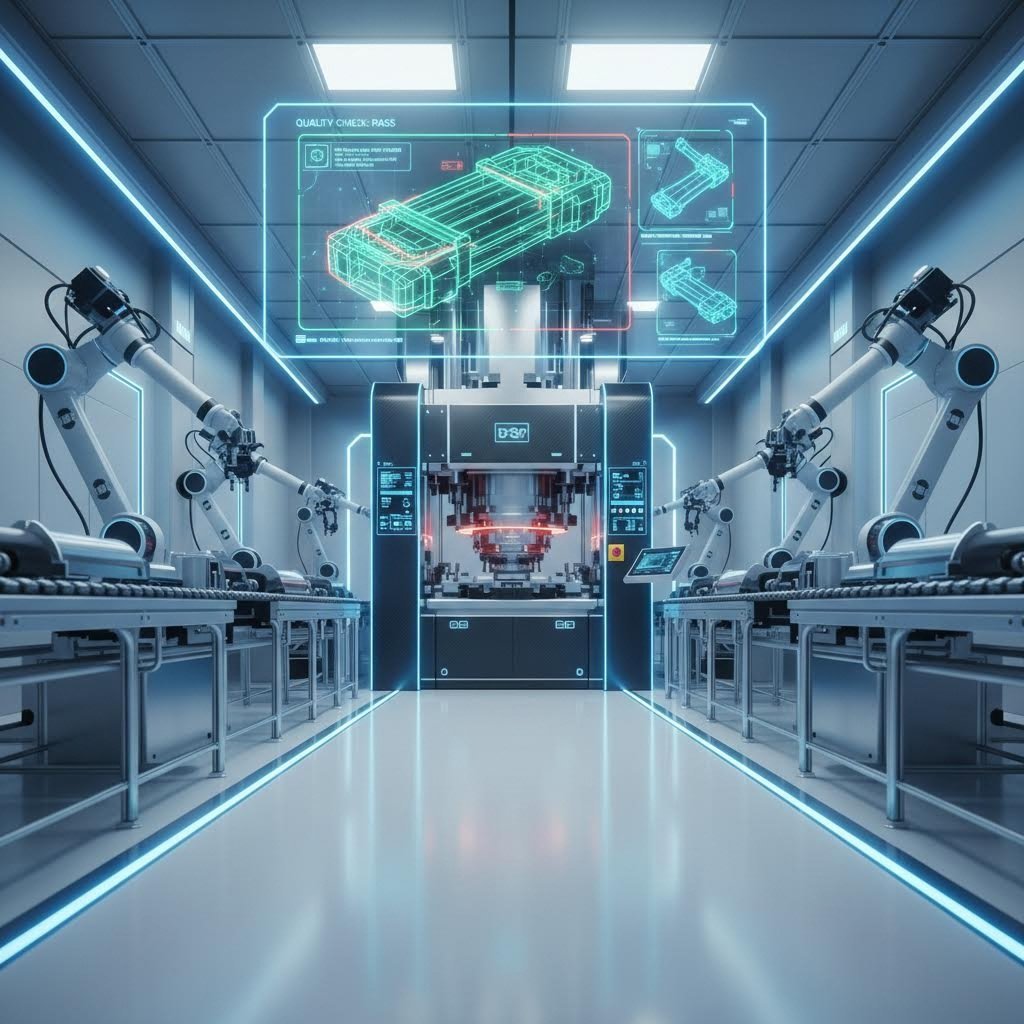
Tecnologias Modernas de Estampagem por Matriz e Automação
Você construiu uma base sólida — compreendendo configurações de matrizes, seleção de materiais, análise de custos e comparações de processos. Mas eis o que distingue os fabricantes que simplesmente sobrevivem daqueles que prosperam: adotar a revolução tecnológica que está transformando todas as máquinas de estampagem por matriz no chão de fábrica. Os equipamentos em operação hoje não se assemelham em nada às prensas de apenas uma década atrás, e compreender esses avanços impacta diretamente a qualidade, a velocidade e o resultado financeiro do seu projeto.
Imagine uma máquina de estampagem por matriz que ajusta automaticamente sua velocidade de conformação durante o curso, com base em feedback em tempo real do material. Visualize inspeções de qualidade ocorrendo automaticamente entre os ciclos da prensa, identificando defeitos antes que eles se multipliquem. Isso não é ficção científica — já está acontecendo agora em operações avançadas de estampagem em todo o mundo. Vamos explorar como essas tecnologias podem beneficiar seu próximo projeto.
Tecnologia que Impulsiona a Inovação na Estampagem
O avanço mais significativo que está transformando as operações de estampagem por matriz é a prensa acionada por servo. Ao contrário das prensas mecânicas tradicionais, que possuem perfis de movimento fixos, as prensas servo utilizam motores programáveis que oferecem controle total sobre o movimento do êmbolo durante todo o curso.
De acordo com Shuntec Press , as prensas servo podem ser programadas para diversas velocidades e posições, tornando-as altamente adaptáveis a diferentes processos de conformação. Essa flexibilidade resulta em melhoria na qualidade das peças, redução do desgaste das ferramentas e menor consumo de energia.
Por que isso é relevante para seus projetos de matrizes de estampagem automotiva ou para operações complexas de conformação? Considere o que o movimento programável permite:
- Velocidades variáveis de aproximação: Aproximação rápida reduz o tempo de ciclo, enquanto a conformação lenta evita defeitos no material
- Tempo de permanência controlado: Manter a pressão no ponto morto inferior melhora a qualidade da cunhagem e do relevo
- Forças de impacto reduzidas: Contato suave com a peça trabalhada prolonga a vida útil da matriz e reduz o ruído
- Compensação de Retorno Elástico: Sobreformação programada aborda a recuperação de material em tempo real
- Regeneração de Energia: Os motores servo consomem energia apenas durante o movimento, com alguns sistemas recuperando energia durante a desaceleração
Segundo a Shuntec Press, o movimento suave e controlado das prensas servo minimiza choques e tensões nas ferramentas. Isso resulta em menores custos de manutenção e menos substituições de ferramentas ao longo do tempo — um benefício direto para o orçamento que se acumula em séries de produção de alto volume.
Para aplicações complexas de estampagem progressiva, a tecnologia servo permite operações que anteriormente eram impossíveis. Extrusões profundas que antes exigiam múltiplos golpes agora podem ser realizadas em um único golpe controlado. Ligas de alumínio de alta resistência, que frustravam as prensas tradicionais, agora são conformadas de forma previsível graças a perfis de movimento precisamente programados.
Sensores Integrados à Ferramenta e Monitoramento em Tempo Real
E se sua ferramenta pudesse avisá-lo quando algo estivesse errado — antes mesmo de peças defeituosas saírem da prensa? É exatamente isso que os sensores integrados à ferramenta oferecem atualmente.
De acordo com o estudo de caso da Penn State Digital Foundry com a JV Manufacturing , os sistemas legados de controle de matrizes ofereciam pouca ou nenhuma visibilidade sobre o desempenho do processo em tempo real ou sobre as causas fundamentais de paradas. Sem monitoramento ou diagnóstico integrados, eventos que afetavam a qualidade passavam despercebidos até após sua ocorrência.
As instalações modernas de máquinas de estampagem com matrizes incorporam sensores que monitoram:
- Assinaturas de tonelagem: Sensores de força detectam variações que indicam alterações no material, desgaste da matriz ou condições de alimentação incorreta
- Presença da peça: Sensores de proximidade confirmam o avanço adequado da tira e a ejeção correta da peça
- Temperatura da matriz: Monitoramento térmico identifica o calor gerado por atrito, sinalizando problemas de lubrificação
- Padrões de vibração: Acelerômetros detectam comportamentos anormais da matriz antes de uma falha catastrófica
- Posição da Chapa: Codificadores verificam a alimentação precisa e o engajamento correto dos guias
O projeto de modernização da fabricação da joint venture, desenvolvido com a Penn State Digital Foundry, criou um controlador de matriz de estampagem de nova geração que integra controladores lógicos programáveis (CLPs), painéis de controle em tempo real, gerenciamento de receitas, funcionalidades de alarme e sensores. O resultado? Uma arquitetura de controle escalável e pronta para a manufatura inteligente, que permite uma resposta mais rápida a problemas de produção e reduz as paradas não planejadas.
Automação e Integração de Fabricação Inteligente
Além da própria prensa, a automação está transformando a forma como as peças se movem nas operações de estampagem. Atualmente, células de máquinas industriais de corte de matrizes integram sistemas robóticos de manipulação que carregam blanks, transferem peças entre operações e empilham componentes acabados — tudo sem intervenção humana.
As tecnologias emergentes que estão redesenhando a eficiência e a qualidade da estampagem com matrizes incluem:
- Manipulação robótica de peças: Robôs de seis eixos transferem peças entre prensas ou carregam/descarregam sistemas alimentados por bobina
- Inspeção guiada por visão: Sistemas de câmera verificam a qualidade das peças, a precisão dimensional e o estado da superfície entre os ciclos de prensagem
- Otimização de Processos Orientada por IA: Algoritmos de aprendizado de máquina analisam dados de produção para recomendar ajustes de parâmetros
- Manutenção Preditiva: Plataformas de análise preveem o desgaste das matrizes e programam a manutenção antes que ocorram falhas
- Simulação de gêmeo digital: Modelos virtuais de matrizes e prensas permitem otimização offline e treinamento de operadores
- Monitoramento conectado à nuvem: Painéis de controle remotos oferecem visibilidade em tempo real da produção em múltiplas instalações
Segundo a Shuntec Press, prensas servo avançadas estão agora sendo equipadas com algoritmos de controle orientados por IA capazes de ajustar automaticamente os perfis de movimento com base no feedback do material ou em variáveis do processo. Esse nível de adaptabilidade melhora a precisão na conformação e reduz erros humanos, tornando as operações mais eficientes e consistentes.
A integração da Indústria 4.0 conecta essas tecnologias individuais em sistemas coesos de manufatura inteligente. Quando sua operação de corte a matriz vincula os controles da prensa, a inspeção de qualidade e o manuseio de materiais em um ecossistema unificado de dados, você obtém insights impossíveis de alcançar com equipamentos isolados. Os gerentes de produção podem identificar tendências, prever problemas e otimizar o desempenho com base em dados operacionais reais, e não em suposições.
Simulação CAE: Prevenção de Defeitos Antes do Primeiro Artigo
Talvez nenhuma tecnologia tenha transformado tanto o desenvolvimento de matrizes para estampagem automotiva quanto a simulação por engenharia auxiliada por computador (CAE). Antes de cortar sequer um único pedaço de aço para ferramentas, os engenheiros já conseguem agora conformar virtualmente peças milhões de vezes, identificando exatamente onde o material sofrerá redução de espessura, enrugamento ou fissuração.
Fabricantes avançados aproveitam a simulação CAE para obter resultados isentos de defeitos por meio de:
- Previsão do comportamento de retorno elástico (springback) e compensação da geometria da matriz antes da fabricação
- Otimizando o tamanho e a forma da chapa para eficiência de material
- Validação do posicionamento das nervuras de tração (draw beads) e dos parâmetros de pressão do segurador de chapinha (blank holder)
- Identificando possíveis fissuras ou enrugamentos antes da tentativa física
- Reduzindo os ciclos de correção de matrizes de semanas para dias
Essa abordagem baseada primeiramente em simulação acelera drasticamente o tempo até a produção. Quando os projetos de matrizes são validados virtualmente, as taxas de aprovação do primeiro artigo atingem valores superiores a 90%, eliminando os dispendiosos ciclos de tentativa e erro que tradicionalmente afetavam o desenvolvimento de ferramentais complexos.
Para projetos que exigem qualidade automotiva, a certificação IATF 16949 garante que os fornecedores mantenham os rigorosos sistemas de gestão da qualidade exigidos pelos principais fabricantes de equipamentos originais (OEMs). Essa certificação abrange desde a validação do projeto até o controle da produção, oferecendo confiança de que seu parceiro em estampagem é capaz de entregar resultados consistentes.
Fornecedores líderes, como a Shaoyi, combinam essas capacidades avançadas — simulação por CAE, sistemas de qualidade certificados e tecnologia moderna de fabricação — para oferecer prototipagem rápida em apenas 5 dias, com taxas de aprovação na primeira tentativa de 93%. Seus soluções abrangentes para matrizes de estampagem automotiva demonstram como as capacidades integradas de engenharia e fabricação transformam esses avanços tecnológicos em sucesso prático nos projetos.
O Futuro da Tecnologia de Estampagem por Matriz
Para onde está caminhando essa evolução tecnológica? Segundo a Shuntec Press, a miniaturização e a modularização dos sistemas servo permitem que os fabricantes personalizem máquinas para aplicações específicas ou restrições de espaço físico. As prensas servo compactas são cada vez mais utilizadas em ambientes de sala limpa e em indústrias especializadas, como a médica e a de microeletrônica.
A convergência entre as pressões por sustentabilidade e a capacidade tecnológica também está remodelando as decisões sobre equipamentos. As prensas servo consomem significativamente menos energia do que os sistemas acionados por volante, alinhando-se às metas corporativas de sustentabilidade ao mesmo tempo que reduzem os custos operacionais. À medida que os fabricantes enfrentam crescente pressão para reduzir suas emissões de carbono, a tecnologia de estampagem energeticamente eficiente torna-se tanto uma exigência ambiental quanto financeira.
Para o seu próximo projeto, esses avanços tecnológicos se traduzem em benefícios concretos: cronogramas de desenvolvimento mais rápidos, taxas mais elevadas de aprovação na primeira tentativa, melhor qualidade das peças e custos de produção mais previsíveis. A questão não é se adotar essas tecnologias, mas sim encontrar o parceiro certo que já investiu nelas. Com essa compreensão das capacidades modernas, você está pronto para mapear todo o processo de planejamento do projeto, desde o conceito inicial até o lançamento na produção.
Planejando seu Projeto de Estampagem com Matriz para o Sucesso
Você absorveu os fundamentos técnicos, analisou os números de custo e avaliou processos alternativos. Agora chegou o momento da verdade: executar, de fato, seu projeto de estampagem por matriz, desde o conceito até o lançamento na produção. É nesse ponto que a teoria encontra a realidade — e onde o planejamento cuidadoso distingue projetos bem-sucedidos de desastres que comprometem o orçamento.
Imagine o planejamento do projeto como a construção de uma ponte. Cada fase se conecta à seguinte, e pular etapas cria lacunas que surgem posteriormente como atrasos, estouros orçamentários ou problemas de qualidade. Seja você está lançando seu primeiro programa de estampagem por matriz ou otimizando uma linha de produção já estabelecida, este roteiro o ajuda a navegar cada marco com confiança.
Seu Roteiro do Conceito à Produção
No que, realmente, se baseia o sucesso na estampagem de metais? Em um planejamento sistemático que antecipa desafios antes que eles comprometam sua linha do tempo. De acordo com 6sigma.us , a diferença entre o sucesso e o fracasso muitas vezes depende de decisões tomadas muito antes de um produto chegar à linha de montagem. A integração precoce dos princípios de Projeto para Fabricação evita correções dispendiosas posteriormente.
Siga esta lista de verificação de planejamento de projeto para orientar seus componentes estampados em matriz, desde o conceito inicial até a produção em série:
- Definir claramente os requisitos do projeto: Documente a função da peça, seu ambiente de montagem e suas características críticas para a função antes de envolver os fornecedores. Segundo a KY Hardware, vá além de um simples desenho da peça — especifique o tipo de material, espessura, estado mecânico (temper) e tolerâncias dimensionais precisas. Requisitos pouco claros levam a orçamentos incorretos e a fornecedores frustrados.
- Realizar uma análise de Projetabilidade para Fabricação (DFM): Antes de finalizar seu projeto, peça a engenheiros especializados em estampagem que o avaliem quanto à viabilidade de produção. Segundo o site 6sigma.us, a Engenharia para Fabricação (DFM) é a prática de projetar produtos tendo em vista sua fabricação — antecipando e resolvendo possíveis desafios produtivos antes que eles surjam. Essa avaliação identifica características que complicam a construção das ferramentas, aumentam os custos ou geram riscos à qualidade.
- Estabeleça Previsões de Volume e Requisitos de Cronograma: Determine sua Estimativa de Uso Anual (EAU) e as quantidades típicas de pedido. Segundo a KY Hardware, essas informações são fundamentais para que o fornecedor defina a abordagem de ferramental mais eficiente e calcule preços precisos. Defina também suas necessidades de prototipagem e o cronograma de lançamento da produção.
- Avalie e Selecione Fornecedores Qualificados: Crie um quadro de pontuação ponderada que abranja as capacidades dos equipamentos, certificações de qualidade, suporte de engenharia, conhecimento especializado em materiais e capacidade produtiva. De acordo com a KY Hardware, o menor preço por peça raramente representa o melhor valor — o verdadeiro valor provém de um fornecedor que atue como parceiro estratégico.
- Solicite e compare cotações: Forneça especificações idênticas a todos os fornecedores potenciais, para permitir uma comparação direta e justa. Certifique-se de que as cotações detalhem separadamente os custos de ferramental, o preço por peça, as operações secundárias e os requisitos de documentação de qualidade.
- Aprovação do projeto da matriz e da engenharia: Revise os modelos 3D CAD, os layouts de tira e os resultados de simulação antes do início da fabricação do ferramental. Esta é sua última oportunidade de influenciar a geometria antes de o aço temperado ser usinado.
- Validação de protótipos: Inspeccione as peças estampadas em metal do primeiro artigo quanto a todos os requisitos dimensionais e funcionais. De acordo com o site 6sigma.us, uma validação e testes minuciosos garantem que o produto atenda a todos os critérios de projetabilidade para fabricação e funcione conforme o previsto.
- Concluir o Processo de Aprovação de Peças para Produção (PPAP): Para aplicações automotivas e industriais, a qualificação formal para produção demonstra que a capacidade do processo atende consistentemente aos requisitos das especificações.
- Escalonamento para Produção Total: Inicie com operações iniciais controladas, monitorando de perto as métricas de qualidade antes de ampliar para a produção em volume total das suas peças estampadas.
Comunicação entre Engenharia de Projeto e Fabricantes de Matrizes
É aqui que muitos projetos enfrentam dificuldades: a transição entre sua equipe de projeto e o fabricante de matrizes. De acordo com o site 6sigma.us, a implementação bem-sucedida da DFM exige colaboração entre diversos departamentos — essa abordagem multifuncional é essencial para o projeto para fabricação e montagem.
Uma comunicação eficaz exige:
- Documentação completa: Fornecer modelos 3D, desenhos 2D com GD&T, especificações de materiais e requisitos de acabamento em formatos de arquivo compatíveis
- Identificação de características críticas: Destacar dimensões e tolerâncias que afetam a funcionalidade, em comparação com aquelas que são meramente estéticas ou menos críticas
- Contexto de aplicação: Explicar como a peça funciona no conjunto — isso ajuda os fabricantes de matrizes a otimizar as ferramentas para o que realmente importa
- Protocolo de gerenciamento de alterações: Estabelecer procedimentos claros para lidar com modificações de projeto após o início da fabricação das matrizes
- Revisões regulares de projeto: Agendar verificações em marcos-chave durante o desenvolvimento das matrizes para identificar problemas precocemente
De acordo com KY Hardware , os melhores fornecedores de estampagem são verdadeiros parceiros que oferecem expertise em engenharia, não apenas capacidade de fabricação. Sua participação precoce pode resultar em economias significativas de custos e em um projeto de peça mais robusto. Pergunte aos fornecedores potenciais: "Você pode me explicar um exemplo recente em que sua equipe de engenharia sugeriu uma alteração de projeto que reduziu custos ou melhorou a fabricabilidade?"
Expectativas de cronograma: do pedido à produção
Agendamento realista evita o pânico que leva a custos de expedição e atalhos na qualidade. Qual cronograma você deve planejar para seu projeto de estampagem de matrizes?
| Fase | Duração Típica | Principais resultados |
|---|---|---|
| Revisão DFM e Cotação | 1-2 semanas | Feedback sobre fabricabilidade, cotação formal e compromisso de cronograma |
| Engenharia de projeto de matrizes | 2-4 semanas | modelos 3D CAD, layouts de tira e validação por simulação |
| Fabricação de ferramentas | 6–10 semanas | Montagem completa da matriz, pronta para teste |
| Teste de Matriz e Primeira Peça | 1-2 semanas | Peças amostra para aprovação dimensional e funcional |
| Qualificação para Produção | 1-2 semanas | Estudos de capacidade, documentação PPAP, se necessário |
| Total: Do conceito à produção | 11–20 semanas | Capacidade de fabricação de matrizes de precisão e estampagem pronta para produção |
Esses prazos pressupõem uma complexidade moderada da matriz. Matrizes compostas simples podem ser concluídas mais rapidamente; matrizes progressivas complexas com muitas estações podem levar mais tempo. Trabalhar com parceiros experientes que investiram em simulações avançadas por CAE e processos eficientes de usinagem pode reduzir significativamente esses prazos.
Parceria para o sucesso na estampagem com matriz
A seleção do seu fornecedor determina, em última instância, se o cronograma do seu projeto será cumprido e se o seu orçamento permanecerá intacto. Segundo a KY Hardware, a escolha do fornecedor adequado para estampagem é uma decisão crítica que afeta diretamente a qualidade do seu produto, o cronograma de produção e o resultado financeiro final.
Critérios-chave para avaliação de fornecedores:
- Capacidades de equipamento: A faixa de tonelagem das prensas e o tamanho da mesa deles atendem aos requisitos da sua peça?
- Certificações de Qualidade: A ISO 9001 é o nível básico; a IATF 16949 demonstra sistemas de qualidade voltados ao setor automotivo
- Profundidade em Engenharia: Eles oferecem revisão DFM, simulação CAE e validação de protótipos internamente?
- Conhecimento em Materiais: Eles já estamparam com sucesso o material especificado por você anteriormente?
- Experiência na Indústria: Eles compreendem os requisitos específicos do seu setor e os processos de aprovação correspondentes?
- Capacidade e flexibilidade: Eles conseguem dimensionar suas operações conforme o crescimento do seu volume e acomodar alterações no cronograma?
Trabalhar com parceiros que combinam expertise em engenharia com capacidades modernas de manufatura acelera sua linha do tempo de produção, ao mesmo tempo que reduz riscos. A equipe de engenharia da Shaoyi exemplifica essa abordagem abrangente, entregando ferramental econômico e de alta qualidade, adaptado aos padrões dos fabricantes originais (OEM). Sua capacidade de prototipagem rápida — produzindo peças amostra em até 5 dias, com taxa de aprovação na primeira tentativa de 93% — demonstra como a integração entre expertise em projeto e fabricação se traduz diretamente em cronogramas de projeto encurtados.
Para projetos que exigem precisão e confiabilidade, explore suas soluções para matrizes de estampagem automotiva ver como as abrangentes capacidades de projeto e fabricação de moldes apoiam tudo, desde o conceito inicial até a produção em grande volume.
A jornada do conceito à produção exige um planejamento cuidadoso, uma comunicação clara e as parcerias certas. Ao seguir este roteiro e ao selecionar fornecedores que atuem como verdadeiros parceiros de engenharia, seu próximo projeto de estampagem por matriz poderá entregar a precisão, a qualidade e a eficiência de custos que justificam o investimento. Seu orçamento agradecerá — e também o seu cronograma de produção.
Perguntas Frequentes Sobre Estampagem de Matrizes
1. Qual é a diferença entre corte por matriz e estampagem?
O corte com matriz e a estampagem de metais são processos fundamentalmente diferentes. O corte com matriz refere-se, normalmente, ao corte de materiais planos, como papel, papelão ou plásticos finos, utilizando lâminas ou regras afiadas. A estampagem de metais, por sua vez, é um processo de conformação a frio que modela chapas metálicas mediante o uso de matrizes especializadas montadas em prensas. A estampagem pode realizar múltiplas operações — corte, dobramento, embutimento e conformação — em um único golpe da prensa, transformando chapas metálicas planas em componentes precisos tridimensionais para as indústrias automotiva, aeroespacial e eletrônica.
2. O que é um estampador de matrizes?
Um estampador de matrizes refere-se tanto ao equipamento quanto ao profissional qualificado que opera máquinas de estampagem de metal. A máquina de estampagem utiliza ferramentas especializadas (matrizes) montadas em prensas hidráulicas ou mecânicas para cortar e conformar chapas metálicas em formas precisas. Na impressão tradicional, um estampador de matrizes é um artesão que grava imagens em blocos de aço. Na indústria de manufatura, os estampadores de matrizes modernos operam prensas acionadas por servomotores, com perfis de movimento programáveis, sensores integrados à matriz e sistemas de monitoramento em tempo real para produzir milhões de peças idênticas.
3. Qual é a diferença entre fundição sob pressão e estampagem?
A fundição em matriz e a estampagem diferem significativamente quanto à forma do material, à temperatura do processo e às aplicações. Na fundição em matriz, o metal é fundido e injetado em moldes sob alta pressão para criar peças tridimensionais complexas — ideal para geometrias intrincadas, mas com custos mais elevados de ferramental. A estampagem metálica utiliza chapas ou bobinas de metal à temperatura ambiente, submetendo-as a matrizes para cortar e conformar as peças. A estampagem oferece custos unitários mais baixos em volumes elevados e destaca-se na produção de suportes, invólucros e componentes que exigem tolerâncias rigorosas.
4. Qual é o custo do ferramental para estampagem em matriz?
Os custos das ferramentas para estampagem a matriz variam significativamente conforme a complexidade. Matrizes compostas simples para operações básicas de corte variam de 5.000 a 15.000 USD. Matrizes progressivas moderadas com 4 a 8 estações custam entre 15.000 e 50.000 USD. Matrizes progressivas complexas, que exigem ferramental intrincado com múltiplas estações, podem atingir valores de 50.000 a 150.000 USD ou mais. Sistemas de matriz de transferência para componentes grandes e profundamente estampados podem custar de 75.000 a 300.000 USD ou mais. Ferramental de qualidade proveniente de fabricantes conceituados garante mais de 1.000.000 de golpes antes da manutenção, tornando esse investimento vantajoso para produção em alta escala.
5. Quando a estampagem com matriz se torna mais econômica do que o corte a laser?
A estampagem com matriz geralmente se torna economicamente vantajosa quando os volumes de produção ultrapassam 10.000 peças anualmente. O cálculo do ponto de equilíbrio divide o investimento em ferramental pela diferença entre os custos por peça dos processos alternativos e os custos por peça da estampagem. Por exemplo, uma matriz progressiva de US$ 25.000 que produz peças a US$ 0,35 cada, comparada ao corte a laser a US$ 2,50 por peça, atinge o ponto de equilíbrio em aproximadamente 11.628 peças. Acima desse limiar, a estampagem gera economias significativas que se acumulam ao longo de programas de produção plurianuais, podendo reduzir os custos até 10 vezes em comparação com processos de corte.