 Kleine series, hoge eisen. Onze snelprototyperingservice maakt validatie sneller en eenvoudiger —

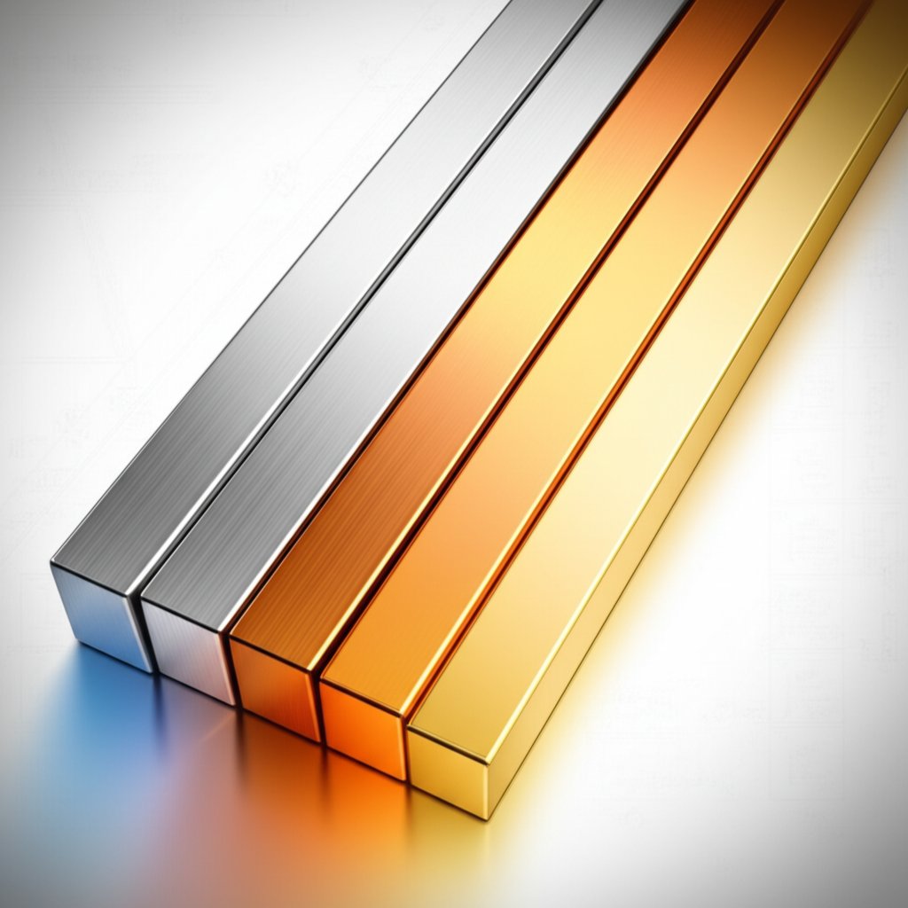
Lineaire uitzettingscoëfficiënt van aluminium vergeleken met staal, koper en messing
Begrijpen van de coëfficiënt van thermische uitzetting in aluminiumtechniek
Wat de coëfficiënt van thermische uitzetting werkelijk betekent
Heb je je ooit afgevraagd waarom aluminiumverbindingen meer speling nodig hebben dan stalen verbindingen? Of waarom een aluminium spoorbaan zich op een hete dag meer uitbreidt dan een stalen baan van dezelfde lengte? Het antwoord ligt in een fundamentele materiaaleigenschap: de coëfficiënt van thermische uitzetting (CTE). Binnen het ontwerp en de fabricage van aluminium is het begrijpen van deze eigenschap essentieel om dimensionale stabiliteit te garanderen, spanningen te minimaliseren en kostbare montageproblemen te voorkomen.
De coëfficiënt van thermische uitzetting beschrijft hoeveel de afmetingen van een materiaal veranderen met temperatuur. Voor de meeste engineeringtoepassingen zijn we geïnteresseerd in de coëfficiënt van lineaire uitzetting —de proportionele lengteverandering per graad temperatuurverandering. In eenvoudige termen: als je een aluminium staaf verwarmt, wordt deze langer; als je het koelt, krimpt het. Maar let op: CTE is geen enkel vast getal. Het kan variëren afhankelijk van het specifieke aluminiumlegeringstype, de hardheid (temper) en het beschouwde temperatuurbereik. Dit betekent dat de aluminum coefficient of thermal expansion die je op een datasheet ziet, vaak een gemiddelde is en mogelijk niet alle nuances bevat die nodig zijn voor precisieontwerp.
Eenheden en dimensionale controles
Klinkt complex? Dat hoeft niet. Om je berekeningen accuraat te houden, let goed op cte units . De meest voorkomende units of thermal coefficient of linear expansion zijn:
- 1/K (per Kelvin)
- µm/m·K (micrometer per meter per Kelvin)
- 10–6/K(vaak gebruikt in engineeringtabellen)
Controleer altijd of je invoer- en uitvoereenheden overeenkomen, vooral wanneer je met metrische en imperiale maten werkt. Deze aandacht voor detail helpt om fouten te voorkomen in tolerantieopstapeling en berekeningen van thermische beweging.
Lineaire versus volumetrische uitzetting: wanneer je elke moet gebruiken
Wanneer gebruik je lineaire uitzetting versus volumetrische uitzetting? Voor de meeste staven, balken en profielen is de lineaire CTE de relevante eigenschap—denk hierbij aan de verandering in lengte langs een enkele as. Volumetrische uitzetting daarentegen beschrijft de verandering in totaal volume (belangrijk voor vloeistoffen of isotrope vaste stoffen). Voor isotrope materialen (die gelijk uitzetten in alle richtingen) is de volumetrische CTE ongeveer drie keer zo groot als de lineaire CTE. Maar in praktische aluminium engineering is lineaire uitzetting meestal de voorkeur gegeven parameter voor passvorm en functionele toepassingen.
- Lineaire CTE : Fractieverandering in lengte per graad temperatuurverandering (primair voor de meeste aluminium onderdelen)
- Gemiddelde versus directe uitzettingscoëfficiënt : De gemiddelde uitzettingscoëfficiënt wordt gemeten over een temperatuurbereik; de directe uitzettingscoëfficiënt is de helling bij een specifieke temperatuur
- Temperatuurinterval-afhankelijkheid : Uitzettingscoëfficiënten kunnen veranderen met temperatuur, geef daarom altijd het bereik op
Belangrijkste conclusie: De coëfficiënt van thermische uitzetting voor aluminium is aanzienlijk hoger dan die van de meeste stalen. Dit verschil bepaalt cruciale ontwerpkeuzes voor openingen, naden en assemblagetoleranties in multimateriaalsystemen.
Terwijl u dit artikel leest, ontdekt u hoe u:
- Thermische uitzetting in realistische aluminium componenten kunt berekenen
- Uitzettingscoëfficiënten en meetnormen kunt interpreteren
- Vergelijk aluminium uitzettingscoëfficiënt met staal, koper en messing
- Pas deze inzichten toe om het risico in uw eigen ontwerpen te minimaliseren
Klaar om verder te gaan? Vervolgens zullen we onderzoeken hoe CTE-waarden veranderen met temperatuur en wat dat betekent voor uw berekeningen en materialenkeuze.
Hoe temperatuur de coëfficiënt van thermische uitzetting in aluminium beïnvloedt
CTE als functie van temperatuur voor aluminium
Wanneer u ontwerpt met aluminium, is het verleidelijk om één getal te nemen voor de coëfficiënt van thermische uitzetting en verder te gaan. Maar is het echt zo simpel? Niet helemaal. De thermische uitzettingscoëfficiënt van aluminium —vaak aangeduid als de ETE—verandert met temperatuur, legeringschemie en zelfs met de manier waarop het materiaal is bewerkt. Als u ooit een aluminium onderdeel hebt opgemerkt dat perfect past bij kamertemperatuur, maar vervolgens vastloopt of loskomt bij verhoogde of onder nul liggende temperaturen, dan heeft u dit uit eerste hand ervaren. Daarom is het begrijpen van de temperatuurafhankelijkheid van de ETE essentieel voor nauwkeurige engineering en betrouwbare prestaties.
Laten we kijken hoe de ETE varieert met temperatuur en legeringen. De volgende tabel vat geautoriseerde gegevens samen voor gangbare aluminiumkwaliteiten en temperatuurbereiken, afkomstig uit peer-reviewed handboeken en overheidsresearch:
| Legering of Serie | Temperatuurbereik (°C) | Gemiddelde ETE (10 –6⁄K) | Directe ETE Opmerkingen | Bron |
|---|---|---|---|---|
| Aluminium 99,99% (Hoogwaardig) | 20–100 | 23.9 | Neemt geleidelijk toe met temperatuur | NIST |
| 1100 (Commerciël zuiver) | 20–100 | 23.6 | Stabiel over dit bereik | Agilent/ASM |
| 6061 (Gesmedeerd legering) | 20–100 | 23.4 | Kleine stijging boven 100°C | ASM/Agilent |
| Gietaluminiumlegeringen (bijv. 4032, A132) | 20–100 | 19.0–20.7 | Lager door hoog Si/Cu gehalte | Agilent/ASM |
| Al-Cu-Mg (bijv. 2024) | 20–100 | 22.8 | CTE neemt af met meer Cu/Mg | Agilent/ASM |
Bron en betrouwbaarheid: Bovenstaande gegevens samengesteld uit NIST en Agilent/ASM gebruikershandleiding . Typische variabiliteit voor gesmeed legeringen is ±0,5 × 10 –6/K over 20–100°C. Het momentane uitzettingscoëfficiënt kan met 5–10% stijgen over een bereik van 300°C voor sommige legeringen.
- Legeringselementen: Het toevoegen van koper, silicium of magnesium kan de cte aluminium verlagen in vergelijking met puur aluminium. Bijvoorbeeld hebben gietlegeringen met een hoog siliciumgehalte merkbaar minder uitzetting.
- Neerslagtoestand: Oplossingstherapie en veroudering kunnen de uitzettingscoëfficiënt omhoog of omlaag veranderen door de microstructuur te veranderen.
- Residu spanningen: Koude werking of ongelijkmatige koeling kan lokale variaties veroorzaken in aluminium temperatuuruitzetting .
- Meetmethode: Verschillende testopstellingen (dilatometrie, interferometrie) en opwarmtempo's kunnen licht verschillende resultaten opleveren, dus controleer altijd de gegevensbron.
Gemiddelde versus directe uitzettingscoëfficiënt
Stel u voor dat u werkt aan een precisieassemblage waarbij enkele micrometers van belang zijn. Moet u de gemiddelde uitzettingscoëfficiënt uit een handboek gebruiken, of iets nauwkeurigers? Dit moet u weten:
- Gemiddelde uitzettingscoëfficiënt wordt berekend over een temperatuurinterval (bijvoorbeeld 20–100°C). Het is geschikt voor grove schattingen of wanneer temperatuurschommelingen matig zijn.
- Directe uitzettingscoëfficiënt is de helling op een specifieke temperatuur, en is cruciaal voor werk met strakke toleranties of waarbij de temperatuur snel varieert. Voor aluminium kan de directe uitzettingscoëfficiënt enkele procenten hoger zijn bij verhoogde temperaturen dan de gemiddelde waarde.
Bijvoorbeeld toont NIST-data aan dat geanodiseerd puur aluminium een gemiddelde uitzettingscoëfficiënt heeft van 23,4 × 10 –6/K van 20–100 °C, maar dit stijgt tot ongeveer 25,5 × 10 –6/K van 20–300 °C. Dat is een aanzienlijk verschil als je ontwerpt voor thermische cycli of extreme omstandigheden ( NIST ).
Dus, val niet in de valkuil om één enkele 'thermische uitzettingscoëfficiënt van aluminium' op te geven voor alle situaties. Geef altijd het temperatuurtrajekt aan en vraag bij hoogwaardig werk of bereken de directe CTE.
Afhaalmaaltijd: De thermische uitzettingscoëfficiënt aluminium is geen waarde die voor alles geschikt is. Het varieert per legering, warmtebehandeling en temperatuur. Voor betrouwbaar technisch ontwerp, bevestig altijd het relevante temperatuurinterval en de gegevensbron.
Vervolgens zullen we zien hoe je dit inzicht toepast op echte berekeningen - zodat je met vertrouwen voorspelt thermische uitzetting van aluminium in je ontwerpen en kostbare verrassingen voorkomt.
Meet CTE op de juiste manier
Standaarden en methoden waarop je kunt vertrouwen
Heb je je ooit afgevraagd hoe ingenieurs die nauwkeurige getallen verkrijgen voor de coëfficiënt van thermische uitbreiding van aluminium of staal? Het begint allemaal met gestandaardiseerde laboratoriummethoden die nauwkeurigheid en reproduceerbaarheid garanderen. Als je termen hebt gezien zoals lineaire uitzettingscoëfficiënt of uitzettingscoëfficiënt in technische rapporten, dan zie je daar het resultaat van zorgvuldig gecontroleerde metingen—vaak uitgevoerd met een apparaat dat een dilatometer .
De meest erkende normen voor het meten van de lineaire uitzettingscoëfficiënt van vaste stoffen zijn:
- ASTM E228 : Lineaire thermische uitzetting met behulp van stangdilatometrie ( referentie )
- ASTM E831 : Thermomechanische analyse (TMA) voor polymeren en composieten
- ISO 11359 serie : Internationale normen voor lineaire en volumetrische thermische uitzetting
Hoe wordt de thermische uitzettingscoëfficiënt gemeten?
Laten we de typische stappen uitleggen, zodat u weet waar u op moet letten in een betrouwbaar laboratoriumrapport:
- Voorbereiding van het monster : Monsters worden tot gestandaardiseerde afmetingen gesneden, vaak cilinders of staven. Voor ASTM E228 zijn diameters tot 12,7 mm en lengtes tot 50,8 mm gebruikelijk.
- Calibratie met referentiematerialen : Voordat de test wordt uitgevoerd, wordt het instrument gekalibreerd met een materiaal met een goed bekende thermische uitzettingscoëfficiënt (zoals vitreus silica).
- Temperatuurverloop : Het monster wordt op een gecontroleerde manier verwarmd of gekoeld. De duwstang of optische sensor registreert lengteveranderingen (voor lineaire uitzetting) of volumeveranderingen.
- Resultatenrapportage : De resultaten omvatten de gemeten coëfficiënt van thermische uitbreiding , het temperatuurinterval, geschatte onzekerheid en reproduceerbaarheid.
| Standaard | Methode Type | Typisch Temperatuurbereik | Gerapporteerde Resultaten | Opmerkingen over Onzekerheid |
|---|---|---|---|---|
| ASTM E228 | Stootstangdilatometrie | -180°C tot 900°C (tot 2500°C met speciale stangen) | Lineaire uitzettingscoëfficiënt, temperatuurinterval | ±0,5–1 × 10 –6/K (afhankelijk van materiaal en methode) |
| ASTM E831 | Thermomechanische analyse | –120°C tot 900°C | Lineair/volume-CTE, TMA-curves | ±1–2 × 10 –6/K typisch |
| ISO 11359-2 | Dilatometrie (algemeen) | -150°C tot 1000°C | Lineaire/volumetrische CTE, onzekerheidsbepaling | Lab-specifiek; vermeld in het testcertificaat |
Bron en betrouwbaarheid: Standaardgegevens en bereiken zijn samengevat uit ASTM E228 en de vermelde ISO/ASTM-documentatie. Vraag altijd het officiële testrapport op voor volledige details over onzekerheid en methode.
Tip: Controleer altijd of een vermelde coëfficiënt van thermische uitbreiding een gemiddelde is over een temperatuurinterval of een differentiële (oomblikkelijke) waarde bij een specifieke temperatuur. Geef nooit een enkelvoudige waarde weer zonder bijbehorend temperatuurbereik en testmethode.
Samenvattend, een betrouwbaar laboratoriumrapport voor de lineaire uitzettingscoëfficiënt of thermische uitzettingscoëfficiënten moet specificeren:
- Monstermeetkunde en voorbereidingsmethode
- Calibratiestandaard en instrumenttype
- Exact bereik van temperaturen dat is getest
- Meetonzekerheid en reproduceerbaarheid
- Of het resultaat een gemiddelde of directe CTE is
Door deze basisbeginselen te begrijpen, kunt u CTE-gegevens zeker interpreteren en mogelijke valkuilen herkennen voordat ze uw ontwerp beïnvloeden. Vervolgens gebruiken we deze meetprincipes om stapsgewijze berekeningsprocessen voor aluminium onderdelen door te nemen - zodat u CTE-waarden met vertrouwen kunt toepassen in uw eigen engineeringprojecten.
Stap-voor-stap berekeningen
Vrije thermische uitzetting in aluminium onderdelen
Heb je je ooit afgevraagd hoeveel langer een aluminium rail wordt op een hete dag? Het antwoord zit in de formule voor thermische uitzetting voor lineaire uitzetting, die voorspelt hoe de lengte van een materiaal verandert met temperatuur:
δL = α · L 0· ΔT
- δL = Lengteverandering (meter of inch)
- α = Coëfficiënt van lineaire uitzetting (typisch aluminium cte waarden liggen tussen 22–24 × 10 –6/K, maar controleer altijd uw legering en temperatuurbereik)
- L 0= Oorspronkelijke lengte van het onderdeel (meter of inch)
- δT = Temperatuurverandering (Kelvin of Celsius; 1 K = 1°C verschil)
Laten we het stap voor stap uitleggen aan de hand van een praktische werkwijze die u kunt toepassen of zelfs in een thermische uitzettingscalculator :
- Bepaal uw variabelen: Haal de oorspronkelijke lengte ( L 0), verwachte temperatuurschommeling ( δT ), en de correcte lineaire uitzettingscoëfficiënt aluminium voor uw specifieke legering en temperatuurbereik.
- Controleer eenheden: Zorg ervoor dat alle metingen in compatibele eenheden zijn — meters of inches voor lengte, Kelvin of Celsius voor temperatuur, en CTE in 1/K of µm/m·K. (Zie onderstaande conversietips.)
- Pas de formule toe: Vermenigvuldig α met L 0en ΔT om ΔL te verkrijgen, de totale verandering in lengte.
- Interpreteer het resultaat: Is de uitzetting significant vergeleken met de toleranties van uw onderdeel of de speling in verbindingen? Zo ja, overweeg dan aanpassingen in het ontwerp.
Bijvoorbeeld, als u een 2-meter aluminium staaf (L 0= 2 m), een temperatuurstijging van 50 °C (ΔT = 50 K), en α = 23 × 10 –6/K, dan:
δL = 23 × 10 –6/K × 2 m × 50 K = 0,0023 m = 2,3 mm
Deze lineaire uitzetting kan van invloed zijn op passvorm, voorbelasting en functie – met name in samenstellingen met nauwe toleranties ( Lumen Learning ).
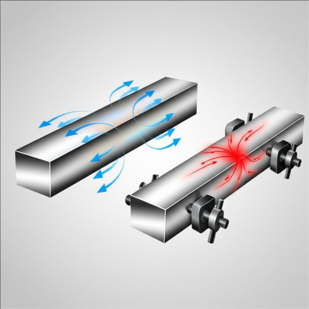
Beperkte uitzetting en thermische spanning
Maar wat als je aluminiumonderdeel zich niet vrij kan bewegen – bijvoorbeeld vastgeschroefd tussen twee stijve stalen platen? In dat geval wordt de thermische uitzetting tegengehouden en ontstaan er mechanische spanningen. De klassieke formule voor thermische groei voor thermische spanning is:
σ = E · α · ΔT
- σ = Thermische spanning (Pa of psi)
- E = Youngs modulus (stijfheid) van aluminium (Pa of psi)
- α = Coëfficiënt van thermische uitzetting (zoals hierboven)
- δT = Temperatuurverandering (K of °C)
Hier is een snelle rekenmethode voor beperkte uitzetting:
- Verzamel materiaaleigenschappen: Zoek E en α voor uw legering en temperatuurtraject.
- Bereken thermische rek: Gebruik dezelfde α en ΔT als hiervoor, maar richt u nu op de resulterende spanning.
- Pas de formule toe: Vermenigvuldig E met α en ΔT om σ te berekenen.
- Vergelijk met de toegestane spanning: Controleer of σ de vloeigrens of ontwerplimieten voor uw toepassing overschrijdt.
Bijvoorbeeld, met E = 70 GPa (typisch voor aluminium), α = 23 × 10 –6/K, en ΔT = 50 K:
σ = 70 × 10 9Pa × 23 × 10 –6/K × 50 K = 80,5 MPa
Deze spanning kan aanzienlijk zijn, vooral als de verbinding al vooraf belast is of als het onderdeel dun is ( Engineering Toolbox ).
Voorzichtigheid: In de praktijk zijn samenstellingen zelden perfect vrij of perfect vastgeklemd. Gedeeltelijke beperking, wrijving en temperatuurgradiënten vereisen geavanceerdere analyse. Gebruik altijd betrouwbare CTE-waarden en raadpleeg voor kritieke ontwerpen een professional of gebruik een gevalideerde thermische uitzettingscalculator.
Eenheidconversies en tips voor consistentie
- 1 mm = 0,03937 inch; 1 inch = 25,4 mm
- 1 K = 1°C verschil; zorg ervoor dat je je eenheden voor de lineaire uitzettingscoëfficiënt (CTE) afstemt op je lengte- en temperatuureenheden
- Voor CTE in µm/(m·K), vermenigvuldig met L 0(in meters) en ΔT (in K) om ΔL in micrometer (µm) te verkrijgen
Consistente eenheden voorkomen kostbare fouten, vooral bij het werken met metrische en imperiale tekeningen.
Daarna ontdek je hoe je deze berekeningen kunt toepassen op realistische constructies, met name wanneer aluminium op staal, koper of messing komt, zodat je constructies kunt ontwerpen die rekening houden met thermische uitzetting, spanningen kunt voorkomen en betrouwbare prestaties kunt waarborgen.
Ontwerp voor CTE-verschillen in realistische aluminiumconstructies
Ontwerp van verbindingen en grensvlakken met CTE-verschillen
Heb je ooit een kier zien ontstaan tussen een aluminium plaat en een stalen beugel na een paar warme dagen? Of merkte je dat een nauwkeurig passende constructie vast kwam te zitten of vervormde na wisseling tussen koude en warme omstandigheden? Dit zijn klassieke symptomen van uitbreiding en samentrekking mismatches, veroorzaakt door de verschillende coëfficiënt van thermische uitzetting waarden voor elk materiaal. Bij het ontwerpen van samenstellingen van verschillende materialen - met name waar aluminium op staal, koper of messing komt - is het begrijpen en plannen van deze verschillen essentieel voor duurzaamheid en functie.
Hieronder vindt u een checklist met best practices om u te helpen omgaan met CTE-mismatch in uw ontwerpen:
- Verlengde naden : Gebruik geneste gaten of verlengde uitsnijdingen in één component om thermische beweging toe zonder vast te lopen of de bevestigingsmiddelen overbelasten.
- Drijvende bevestigingsmiddelen : Kies bevestigingsmiddelen die enige zijdelingse beweging toelaten, zodat de samenstelling zich vrij kan uitbreiden of inkrimpen met temperatuurveranderingen.
- Compliërende interfaces : Neem pakkingen, flexibele lijm of elastomeren op om differentiële beweging op te nemen en spanningconcentraties te verminderen.
- Gereguleerde openingen : Ontwerp opzettelijke spelingen bij aansluitingen, met name waar de aluminium lineaire uitzettingscoëfficiënt veel hoger is dan het aansluitende materiaal.
- Compatibele Materialen : Kies indien mogelijk materialen met een vergelijkbare uitzettingscoëfficiënt of gebruik overgangslagen om het risico op mismatch te beperken.
| Materiaal | Typisch CTE-bereik (10 –6⁄K) | Kwalitatief risico op mismatch (t.o.v. aluminium) | Ontwerptactiek |
|---|---|---|---|
| Aluminium | 22–24 | — | Vergelijkingsreferentie |
| Staal (koolstof, legering) | 11–15 | Hoog (thermische uitzetting van staal is veel lager) | Spleten, zwevende bevestigingsmiddelen, veerkrachtige verbindingen |
| Roestvrij staal | 10–17 | Middelbaar-hoog (cte van roestvrij staal varieert per kwaliteit) | Vergroot de spelingen, gebruik flexibele lijm |
| Koper | 16–18 | Middelbaar (dichter bij aluminium, maar nog steeds aanzienlijk) | Matige afstand, flexibele interface |
| Messing | 18–19 | Medium (brons zit dichter bij aluminium) | Standaardpassend kan volstaan; controleer toleranties |
Bron en betrouwbaarheid: Typische CTE-bereiken samengesteld uit Master Bond en Engineering Toolbox . Bevestig altijd legeringspecifieke waarden voor kritieke toepassingen.
Stel je voor: een aluminium paneel dat met bouten is bevestigd aan een stalen frame. Bij stijgende temperaturen wil het aluminium bijna twee keer zo veel uitzetten als het staal. Zonder een ontwerpoplossing—zoals een verlengd gat of zwevende bevestiging—kan deze differentiële beweging leiden tot kromtrekken, vervorming of zelfs verbindingverlies. Daarom is het zo belangrijk om rekening te houden met de lineaire uitzettingscoëfficiënt van aluminium bij elke assemblage met gemengde materialen.
Thermische bewegingsbegroting op tekeningen
Hoe vertaal je al deze theorie naar praktische, realiseerbare ontwerpen? Het begint met duidelijke documentatie en een proactieve aanpak van toleranties:
- Wijs toleranties toe voor thermische beweging: Bereken de verwachte uitzetting of samentrekking voor elk onderdeel binnen het werktemperatuurbereik (ΔT). Gebruik de aluminium-uitzettingscoëfficiënt en de bijbehorende waarde voor elk passend materiaal.
- Kies zorgvuldig tussen gemiddelde en directe uitzetcoëfficiënt (CTE): Voor grote temperatuurschommelingen is een gemiddelde CTE meestal geschikt. Voor precisiepassingen of snelle temperatuurwisselingen, gebruik dan de directe CTE bij de relevante temperatuur.
- Documenteer aannames: Noteer altijd het aangenomen temperatuurbereik en de bron van je CTE-gegevens direct op de tekening of in een ontwerpnotitie. Dit voorkomt dubbelzijdigheid en ondersteunt toekomstig probleemoplossing of herontwerp.
- Valideer met testen: Voor kritieke of veiligheidsgerelateerde samenstellingen, prototypeer en test onder echte thermische wisselingen om te bevestigen dat beweging en spanning binnen veilige limieten blijven.
Belangrijkste conclusie: Een samenstelling overmatig beperken met niet-overeenkomstige CTE's kan verborgen spanningen en vroege storingen veroorzaken. Proactief ontwerp - met gebruik van sleuven, flexibele scharnieren en duidelijke documentatie - stelt u in staat de voordelen van gemengde materialen te benutten zonder de risico's.
Met deze praktische tools kunt u vertrouwd ontwerpen voor thermische beweging en zorgt u voor robuuste, duurzame samenstellingen. Vervolgens zullen we zien hoe aluminium's CTE zich verhoudt tot andere constructiemetalen - waardoor u slimme keuzes kunt maken voor uw volgende project.
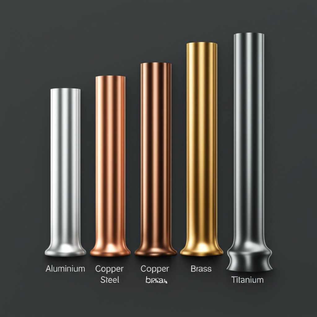
Vergelijking van de Coëfficiënt van Thermische Uitzetting
Hoe aluminium zich verhoudt tot gangbare constructiemetalen
Wanneer u materialen selecteert voor een samenstelling, heeft u zich ooit afgevraagd waarom sommige verbindingen openen of vastlopen na een temperatuurschommeling? Het antwoord komt vaak neer op hoeveel elk materiaal uitzet of krimpt bij warmte - en dat is waar de coëfficiënt van thermische uitzetting (CTE) wordt je beste ontwerpcollega. Laten we aluminium naast staal, koper, messing en titaan plaatsen, zodat je kunt zien hoe hun CTE's zich verhouden in de praktijk.
| Materiaal | Typisch CTE-bereik (10–6⁄K) |
Temperatuurtoepasbaarheid (°C) |
Practische uitzetting per meter per 100 K (mm) |
Opmerkingen over variabiliteit |
|---|---|---|---|---|
| Aluminium (1100, 6061, 2024, etc.) | 22.3–24.1 | –40 tot 300 | 2.2–2.4 | Legering en temperatuurafhankelijk; hoger dan de meeste metalen |
| Staal (koolstof, legering) | 10.8–13.0 | –40 tot 500 | 1.1–1.3 | Lager voor koolstofstaal; hoger voor sommige roestvrijstalen |
| Roestvrijstaal (bijv. 304, 316) | 16.0–17.3 | –40 tot 500 | 1.6–1.7 | Roestvrijstalen lineaire uitzettingscoëfficiënt stijgt met nikkelgehalte |
| Koper | 16.5–17.7 | –40 tot 300 | 1.65–1.77 | Koper lineaire uitzettingscoëfficiënt is stabiel over gangbare temperaturen |
| Messing (patroon, geel, maritiem) | 18.4–20.9 | –40 tot 300 | 1.84–2.09 | Lineaire uitzettingscoëfficiënt van messing afhankelijk van zink/koper verhouding |
| Titanium (zuiver, Ti-6Al-4V) | 8.4–9.4 | –40 tot 400 | 0.84–0.94 | Zeer stabiel, ideaal voor precisie-assenbleerwerken |
Bron en betrouwbaarheid: Gegevens samengesteld uit Agilent/ASM gebruikershandleiding en Engineering Toolbox. Bereiken geven gangbare vervormbare legeringen en commerciële kwaliteiten weer; controleer altijd voor uw specifieke toepassing.
- Thermische uitzetting van koellichaambasisplaat: Het hoge uitzettingscoëfficiënt van aluminium betekent dat het meer uitzet dan koper of staal, wat van invloed is op de montage en thermische interface.
- Bimetalenvervormingen: Aluminium aan staal of titaan bevestigen kan vervorming of kromtrekken veroorzaken bij temperatuurschommelingen door het verschil in uitzettingscoëfficiënt.
- Spooralijndrift: Lange aluminium profielen of extrusies bewegen meer per graad dan staal of koper, wat van invloed is op precisie-assen en -geleiders.
Materialen kiezen voor gemengd metaal-systemen
Stel je voor dat je een precisie-frame of een warmtewisselaar bouwt. Moet je altijd vermijden om materialen met verschillende CTE's te mengen? Niet noodzakelijk. Zo maak je slimme keuzes:
- Hogere CTE van aluminium kan een voordeel zijn in veerkrachtige of zwevende verbindingen, waar spanningsoptreeding gewenst is. Bijvoorbeeld in autowarmteschermen of flexibele beugels, waarbij de uitzetting wordt opgenomen zonder schade.
- Risico voor precisie: In toepassingen zoals optische montage of meetgeleiders, waarbij positioneringsnauwkeurigheid cruciaal is, kan de uitzetting van aluminium leiden tot onaanvaardbare drift. In dergelijke gevallen zijn titaan of staal met lage uitzetting voorkeursmaterialen.
- Thermische vermoeidheid: Herhaaldelijk schakelen tussen materialen met verschillende CTE's (zoals koper en aluminium in stroomrails) kan vermoeidheid veroorzaken, dus ontwerp voor flexibiliteit of gebruik compatibele legeringen.
- Documenteer CTE-gegevens: Geef altijd de daadwerkelijke coëfficiënt van thermische uitzetting staal , koper coëfficiënt van thermische uitzetting , of brons coëfficiënt van thermische uitzetting gebruikt in uw berekeningen aan, en vermeld het temperatuurbereik op uw tekeningen.
Zoals je kunt zien, de coëfficiënt van thermische uitzetting is veel meer dan alleen een tabelopzoeking – het is een fundamentele drijfveer voor passvorm, functie en betrouwbaarheid in elke samengestelde metaalconstructie. In de volgende sectie brengen we deze concepten in de wereld van het aluminiumprofiel inkopen, waarin wordt aangetoond hoe u de CTE kunt specificeren en valideren voor realistische productie.
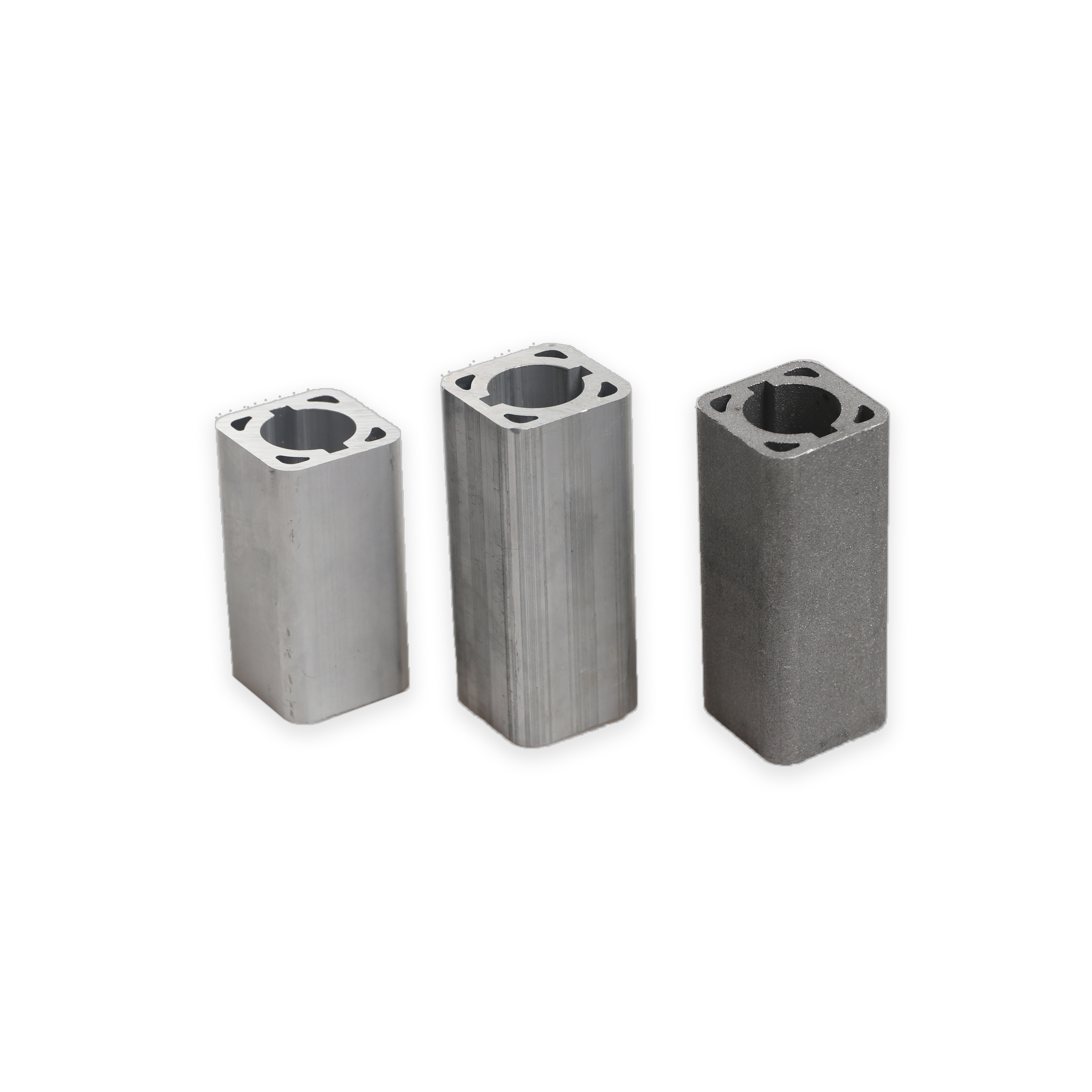
Inkopen en Specificeren van Aluminiumprofielen
Het specificeren van aluminiumprofielen met thermisch gedrag in gedachten
Wanneer u aluminiumprofielen inkoopt voor kritische constructies – met name in de automotive of constructieve toepassingen – is het niet voldoende om simpelweg een legering te kiezen en uw tekeningen naar een leverancier te sturen. Hebt u zich ooit afgevraagd waarom een onderdeel dat perfect past in de werkplaats, plotseling vastloopt of openingen vertoont na de afwerking of installatie ter plaatse? Het antwoord ligt vaak in de thermische uitzettingscoëfficiënt voor aluminium en hoe deze wordt meegenomen tijdens de specificatie en productie.
Om ervoor te zorgen dat uw geperste onderdelen zich gedragen zoals verwacht onder alle werkomstandigheden, volgt hier een praktische checklist voor ingenieurs en kopers:
- Kies het juiste legeringstype en de juiste hardheid: Verschillende aluminiumlegeringen (zoals 6061, 6082 of 7075) hebben verschillende aluminium thermische uitzettingscoëfficiënt waarden en mechanische eigenschappen. Zorg er altijd voor dat de legering geschikt is voor zowel de sterkte- als thermische eisen van uw ontwerp ( Aluminum Extrusion Manual ).
- Geef het temperatuurbereik voor toleranties aan: Geef voordat u een tekening goedkeurt het volledige temperatuurbereik op dat het onderdeel tijdens gebruik zal ondervinden. Dit zorgt ervoor dat toleranties worden ingesteld met warmte-uitzetting van aluminium in gedachten - niet alleen passingen bij kamertemperatuur.
- Geef de CTE-bron aan op tekeningen: Of u nu handboekgegevens, testresultaten van leveranciers of een specifieke norm gebruikt, verwijst u altijd naar de aluminium thermische coëfficiënt (en de bron ervan, inclusief het temperatuurinterval) direct op uw tekening. Dit vermindert dubbelzijdigheid en helpt downstream teams bij het interpreteren van uw intentie.
- Valideer passingen na afwerkprocessen: Oppervlaktebehandelingen zoals anodiseren of schilderen kunnen dikte toevoegen of afmetingen veranderen. Controleer en registreer altijd de uiteindelijke passform na alle afwerkstappen, omdat nabewerking invloed kan hebben op de lineaire uitzetting van aluminium lokaal.
Samenwerking met ervaren extrusieleveranciers
Voor automotive- en high-performance toepassingen is het essentieel om samen te werken met een leverancier die zowel materiaalkunde als procesbeheersing begrijpt. Waarom? Omdat de thermische uitzettingscoëfficiënt van aluminium is niet zomaar een getal, het is een variabele die samenwerkt met de chemie van legeringen, het extrusieproces en de afwerkingsbehandelingen. Samenwerken met een partner die deze variabelen kan documenteren, testen en controleren, kan het verschil maken tussen een probleemloze lancering en een kostbare herontwerp.
Bij het inwinnen met een diameter van niet meer dan 30 mm met gedocumenteerde CTE-gegevens en sterke procescapaciteit, kunt u de volgende leveranciers overwegen:
- Shaoyi Metal Parts Supplier – Een toonaangevende leverancier van geïntegreerde oplossingen voor precisie-autometalen onderdelen in China, die IATF 16949-gecertificeerde aluminium extrusieproducten, volledige traceerbaarheid en deskundig advies biedt bij de selectie van legeringen en CTE-beheer voor toepassingen in de automobielindustrie.
- Lokale of regionale extrusiefabrieken met interne test- en afwerkingsmogelijkheden
- Wereldwijde leveranciers gespecialiseerd in architectonische of transportkwaliteit extrusies
Voor auto-extrusieprogramma's helpt het samenwerken met ervaren leveranciers om materiaalkeuze, procesbeheersing en dimensionale stabiliteit over ΔT te laten samenvallen. Dit is met name belangrijk wanneer de aluminium thermische uitzettingscoëfficiënt moet worden strikt beheerst om de betrouwbaarheid van onderdelen in gebruik te garanderen.
Belangrijke punten: Documenteer altijd uw CTE-aannames en temperatuurbereiken op tekeningen. Na afwerkprocessen (zoals anodiseren), controleer eventuele dimensionale veranderingen en werk passende controlebijsteken bij. Plan proactief de spelingen bij assenblijving om warmte-uitzetting van aluminium en vermijd kostbare herwerking of defecten in het veld.
Waarom CTE-documentatie en validatie belangrijk zijn
Stel je voor dat je een batch extrusierails levert voor een EV-batterijbak. Als de thermische uitzettingscoëfficiënt voor aluminium niet duidelijk is gedefinieerd en gevalideerd, kunnen zelfs kleine temperatuurschommelingen leiden tot misalignement, spanningopbouw of lekken. Door de CTE-bron te specificeren, de postprocess-dimensies te valideren en ruimte in te plannen voor thermische uitzettingscoëfficiënt van aluminium in uw assemblage zorgt u voor robuuste, reproduceerbare prestaties, zelfs in veeleisende omgevingen.
Klaar om deze best practices in werking te zetten? In de volgende sectie vatten we de belangrijkste lessen samen en bieden we praktische vervolgstappen voor het integreren van CTE-beheer in uw engineering- en inkoopprocessen.
Kerninzichten samenvatten en overgaan tot verzekerd optreden
Belangrijkste conclusies over aluminium CTE
Hebt u zich ooit afgevraagd: 'Wat is de coëfficiënt van thermische uitzetting, en waarom is die zo belangrijk in de praktijk van engineering?' Na het verkennen van de wetenschap, normen en praktische werkwijzen in deze gids, is het duidelijk dat het begrijpen en beheren van de lineaire uitzettingscoëfficiënt van aluminium essentieel is voor betrouwbare, hoogwaardige assemblages, vooral wanneer temperatuurschommelingen deel uitmaken van uw werkomgeving.
- Temperatuurafhankelijkheid: De thermische uitzettingscoëfficiënt van aluminium is geen vaste waarde. Het varieert per legering, tempering en vooral per temperatuurbereik. Controleer altijd het relevante interval voor uw toepassing.
- Meetstandaarden: Betrouwbare CTE-waarden vereisen strenge laboratoriummethoden en verwijzing naar standaarden zoals ASTM E228 en ISO 11359. Vraag altijd de onzekerheid en testgegevens aan bij uw leverancier.
- Berekeningswerkstroom: Gebruik duidelijke formules voor vrije en beperkte expansie, en kies afhankelijk van de precisiebehoefte van uw ontwerp voor gemiddelde of ogenblikkelijke waarden. Vergeet niet de eenheden af te stemmen en aannames te documenteren.
- Afwegingen tussen materialen: Het hogere CTE van aluminium in vergelijking met staal, koper of messing betekent dat u moet ontwerpen voor thermische samentrekking en expansie – vooral bij verbindingen, grensvlakken en samenstellingen waar verschillende metalen op elkaar aansluiten.
Belangrijkste kenmerk: Elke geciteerde CTE – of het nu voor de coëfficiënt van uitzetting van aluminium of een ander materiaal—moet het temperatuurbereik, de meetmethode en de onzekerheid worden gespecificeerd. Beperkte omstandigheden kunnen aanzienlijke thermische spanningen veroorzaken, ontwerp daarom altijd met zowel uitzetting als krimp in gedachten.
Praktische volgende stappen voor ingenieurs en kopers
Klaar om deze kennis in actie te brengen? Als u werkt aan auto-extrusies of precisie-assen waarbij dimensionale stabiliteit over grote temperatuurschommelingen kritiek is, overweeg dan samenwerking met een leverancier die zowel technische expertise als sterke kwaliteitssystemen biedt. Bijvoorbeeld: Shaoyi Metal Parts Supplier biedt geïntegreerde oplossingen voor met een diameter van niet meer dan 30 mm , inclusief gedocumenteerde CTE-gegevens, IATF 16949-certificering en uitgebreide ondersteuning voor legeringkeuze en procesvalidatie. Hun aanpak zorgt ervoor dat uw definitieve ontwerp correct rekening houdt met zowel thermische uitzetting als thermische samentrekking , waardoor het risico op uitval of onjuiste pasvorm in de praktijk wordt geminimaliseerd.
Als u leveranciers vergelijkt, zoek dan naar leveranciers die:
- CTE-gegevens leveren met gedocumenteerde testmethoden en temperatuurintervallen
- Verwijs in technische documentatie naar erkende normen (ASTM, ISO)
- Ondersteun postprocessingvalidatie (bijvoorbeeld na anodiseren of bewerken)
- Biedt engineeringondersteuning voor tolerantie- en pasanalyse over het volledige werktemperatuurbereik
En vergeet niet—vermeld op elke tekening of specificatie duidelijk de aangenomen CTE-waarde, de bron en het toepasselijke temperatuurbereik. Deze eenvoudige praktijk helpt om uw ontwerpen toekomstbestendig te maken en verwarring te voorkomen tijdens de productie of bij het oplossen van problemen.
Laatste gedachte: Het beheersen van de cTE van aluminium gaat niet alleen om getallen—het gaat om het nemen van verstandige, goed onderbouwde beslissingen die standhouden in de praktijk. Documenteer uw aannames, valideer met vertrouwde partners, en u zult samenstellingen bouwen die betrouwbaar presteren, ongeacht de temperatuurveranderingen.
Veelgestelde vragen over de coëfficiënt van thermische uitzetting
1. Wat is de coëfficiënt van thermische uitzetting en waarom is deze belangrijk in de techniek?
De lineaire uitzettingscoëfficiënt (CTE) meet hoeveel een materiaal van afmeting verandert bij temperatuurveranderingen. In de techniek helpt het kennen van de CTE om problemen te voorkomen zoals voegopeningen, vervorming of spanningopbouw, vooral wanneer materialen zoals aluminium en staal worden gecombineerd. Het opgeven van de juiste CTE zorgt voor betrouwbare passingen en duurzaamheid op lange termijn in constructies.
2. Hoe verhoudt de uitzettingscoëfficiënt van aluminium zich tot die van staal, koper en messing?
Aluminium heeft over het algemeen een hogere CTE dan staal, wat betekent dat het meer uitzet en krimpt bij temperatuurveranderingen. Koper en messing hebben CTE-waarden die dichter bij aluminium liggen, maar nog steeds iets lager zijn. Dit verschil maakt CTE-onderlinge afstemming een belangrijke overweging bij het ontwerpen van constructies met gemengde metalen om vervorming of verbindingverval te voorkomen.
3. Hoe wordt de lineaire uitzettingscoëfficiënt gemeten voor metalen zoals aluminium?
CTE wordt gemeten met gestandaardiseerde methoden zoals ASTM E228 of ISO 11359, waarbij een zorgvuldig voorbereid monster wordt verwarmd en de dimensionale verandering wordt geregistreerd. Betrouwbare laboratoria rapporteren het temperatuurbereik, de onzekerheid en of de waarde gemiddeld of ogenblikkelijk is, zodat ingenieurs beschikken over de benodigde gegevens voor nauwkeurige berekeningen.
4. Waarom moet het temperatuurbereik worden gespecificeerd bij het vermelden van een CTE-waarde?
CTE-waarden kunnen variëren met temperatuur, legering en verwerking. Het opgeven van het temperatuurbereik zorgt ervoor dat de gebruikte CTE overeenkomt met de realistische omstandigheden, wat leidt tot nauwkeurigere voorspellingen van uitzetting of krimp en het risico op passproblemen of spanningen in de eindmontage vermindert.
5. Hoe kunnen automobielingenieurs omgaan met CTE bij het inkopen van aluminiumprofielonderdelen?
Automobiel ingenieurs moeten het juiste legering en tempering selecteren, het opgegeven temperatuurbereik vastleggen en de CTE-waarden documenteren in tekeningen. Samenwerken met ervaren leveranciers zoals Shaoyi Metal Parts Supplier zorgt voor toegang tot gedocumenteerde CTE-waarden, kwalitatief hoogwaardige productie en ontwerpondersteuning om rekening te houden met thermische uitzetting en krimp in kritieke auto-onderdelen.