 Mažas partijas, augsti standarti. Mūsu ātra prototipēšanas pakalpojums padara validāciju ātrāku un vieglāku —

Matricas un spiediena izgatavošanas noslēpumi: kāpēc 80 % defekti ir novēršami
Matricu un stempelēšanu ražošanā — izpratne
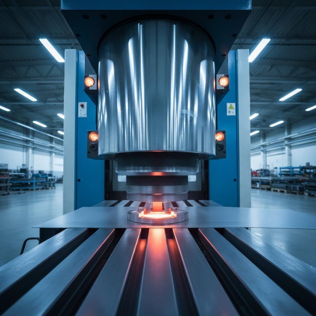
Kad jūs dzirdat ražotājus runājam par miljoniem identisku metāla detaļu ražošanu ar izcilu precizitāti, viņi gandrīz noteikti runā par matricu un stempelēšanas procesiem. Bet kas ir metāla stempelēšana un kāpēc tā joprojām paliek augstas apjoma ražošanas pasaules pamats ?
Matricu un stempelēšana ir aukstās deformācijas ražošanas process, kurā specializēta rīku aprīkojuma (matricu) sadarbībā ar stempelēšanas presēm plakanu loksnes metālu pārveido precīzās, iepriekš noteiktās formās, veicot darbības, piemēram, griešanu, liekšanu un veidošanu.
Šī stempelēšanas definīcija atspoguļo būtību procesam, kas nodrošina darbību no automobiļu līdz kosmosa rūpniecībai. Izpratne par to, kā matricas un stempelēšana darbojas kopā, ir jūsu pirmais solis, lai novērstu defektus, kas skar 80 % nepietiekami labi pārvaldītu operāciju.
Matricu un stempelēšanas attiecību skaidrojums
Iedomājieties matricas kā pielāgotus veidņu rīkus, kas nosaka, kā izskatīsies jūsu gatavais produkts. Tātad, kas ir matrica ražošanā? Tā ir specializēta rīku sistēma, kas izstrādāta, lai ar ārkārtīgu precizitāti grieztu, veidotu vai deformētu metālu. Stempļu preses uzdevums ir nodrošināt spēku, bet matricas uzdevums — precizitāti.
Šī rīku un matricu definīcija palīdz skaidri atšķirt svarīgu jēdzienu: stempļošana attiecas uz vispārējo procesu, bet matricas ir kritiskie rīku komponenti, kas to padara iespējamu. Kad plakanā metāla loksne tiek ievadīta stempļu presē, matrica to pārveido, izmantojot spiedienu un precīzi izstrādātas kontaktvirsmas. Rezultāts? Iegūst vienveidīgus, atkārtojamus produktus, ko ražot ātrumā, kādu citi metodi vienkārši nevar sasniegt.
Kāpēc matricas ir būtiskas modernajā ražošanā
Jūs varētu brīnīties, kāpēc šī desmitgadēm vecā tehnoloģija joprojām ir būtiska, kad pastāv jaunākas ražošanas metodes. Atbilde slēpjas efektivitātē un ekonomikā. Saskaņā ar Schaumburg Specialties — pieaugošais globālais pieprasījums pēc masveida ražotiem sarežģītiem detaļām padara metāla stempelēšanu izdevīgu risinājumu bezskaita pielietojumos.
Ko var ražot stempelēšanas operācija? Uzskaitījumā ietilpst automobiļu komponenti, aviācijas daļas, medicīniskās ierīces, elektronisko ierīču korpusi un ikdienas mājsaimniecības piederumi. Šī universālā lietojuma iespēja izskaidro, kāpēc jebkuram personas, kas iesaistīta iepirkumu vai ražošanas lēmumu pieņemšanā, ir svarīgi saprast, kas ir matricas ražošanā.
Šajā rakstā jūs atklāsiet noslēpumus, kā novērst biežāk sastopamos stempelēšanas defektus, iemācīsieties izvēlēties piemērotākās matricu tipus savām lietojumprogrammām un iegūsiet praktiskus ieskatus materiālu izvēlē, kvalitātes kontrolē un apkopes labākajās praksēs. Vai nu jūs esat jauns šajā ražošanas metodē, vai arī meklējat veidus, kā optimizēt esošās operācijas, šie ieskati palīdzēs jums sasniegt labākus rezultātus.
Stempelēšanas matricu tipi un to lietojuma gadījumi
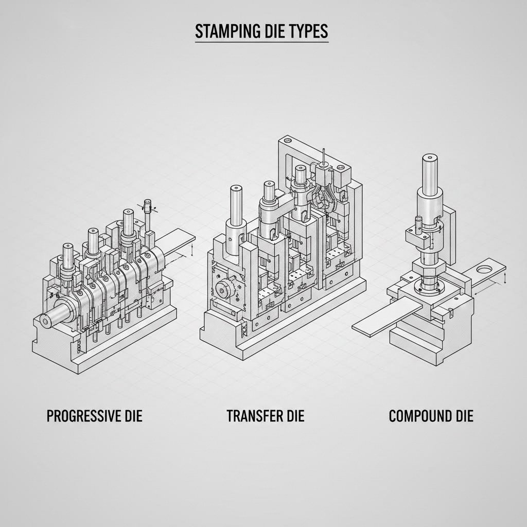
Pareizās stempļu matricas izvēle nav tikai tehnisks lēmums — tā ir pamats defektiem novēršanai jau to rašanās sākumā. Ar trīs galveno matricu veidu dominēšanu rūpniecībā, to stipro un vājo pušu izpratne palīdz jums savienot ražošanas prasības ar optimālo rīku risinājumu. Apskatīsim progresīvās stempļu matricas, pārvades matricas un salikto matricu, lai jūs varētu pieņemt apsvērtus lēmumus.
Progresīvās matricas augstas ātruma ražošanai
Iedomājieties montāžas līniju, kur vairākas operācijas notiek vienlaicīgi, kamēr metāls pārvietojas caur dažādām stacijām — tieši tā darbojas progresīvā stempļu procesa metode. Šīs sofistikātās matricas veic secīgas operācijas piemēram, griešanu, urbšanu un liekšanu, kamēr metāla lenta pārvietojas no stacijas uz staciju katrā preses kustībā.
Kāpēc ražotāji mīl progresīvās matricas? Saskaņā ar JV Manufacturing, tās ir darba zirgi augstas apjoma ražošanas līnijās, īpaši sarežģītiem komponentiem, kuriem nepieciešami daudzi veidošanas soļi. Progresīvās matricas stempelēšanas process ir īpaši efektīvs, ja nepieciešams:
- Stabils sarežģītu komponentu ražošanas process ar vairākām funkcijām
- Augsta ātruma izstrādājumu ražošana lieliem apjomiem
- Mazāka manipulācija starp operācijām
- Zemākas vienības izmaksas lielos apjomos
Tomēr progresīvām matricām nepieciešama ievērojama sākotnēja investīcija. Tās prasa modernas preses sistēmas un kvalificētus operatorus, lai nodrošinātu bezšuvju darbību. Ražotājiem, kas lielos apjomos ražo automobiļu komponentus, elektronikas korpusus vai sarežģītus mehāniskus komponentus, šī investīcija parasti atmaksājas, ievērojami samazinot izmaksas par vienu komponentu.
Šeit ir svarīga materiāla biezums. Progresīvie matricu veidi vislabāk darbojas ar plānākiem materiāliem, kuru biežums parasti ir no 0,005" līdz 0,250". Biezāki materiāli rada pārmērīgu slodzi matricu stacijās un var samazināt precizitāti secīgajās operācijās.
Pārvades matricas pretī kombinētajām matricām
Kad progresīvās matricas neatbilst jūsu pielietojumam, pārvades stempelēšana un kombinētās matricas piedāvā spēcīgas alternatīvas — katra no tām apkalpo atsevišķas ražošanas vajadzības.
Pārnešanas veidnes mekhāniski pārvieto atsevišķas detaļas no vienas stempelēšanas stacijas uz nākamo, līdzīgi kā prasmīgs amatnieks pārdod darbu starp specializētām darba vietām. Šī metode ir īpaši efektīva lielāku un sarežģītāku detaļu ražošanā, kurām nepieciešamas vairākas secīgas operācijas. Kā norāda Worthy Hardware, pārvades matricu stempelēšana nodrošina lielāku elastību detaļu apstrādē un orientācijā, tādējādi padarot to piemērotu sarežģītiem dizainiem un formām.
Pārvades matricas efektīvāk apstrādā biezākus materiālus nekā progresīvās matricas, pieļaujot biezumus no 0,020" līdz 0,500" vai vairāk, atkarībā no konkrētās konstrukcijas. Tāpēc tās ir ideālas strukturālo komponentu un biezmateriālu lietojumiem.
Saliktās matricas savukārt kombinētās matricas vienlaikus veic vairākas operācijas vienā darba ciklā. Iedomājieties, ka griešana un urbšana notiek tieši vienlaikus. Tās bieži izmanto uzdevumiem, kuriem nepieciešama augsta ātruma precizitāte, piemēram, elektronikas vai medicīnas aprīkojuma daļu ražošanai. Kaut arī tās ir lēnākas nekā progresīvās matricas, kombinētās matricas nodrošina izcilu precizitāti vienkāršām, plakanām daļām.
Kombinētās matricas parasti strādā ar materiāla biezumiem no 0,010" līdz 0,375", atkarībā no materiāla cietības un vienlaikus veicamo operāciju sarežģītības.
| Iemesls | Progressīvajām matricām | Pārnešanas veidnes | Saliktās matricas |
|---|---|---|---|
| Daļas sarežģītība | Augsts — vairākas funkcijas, sarežģīti dizaini | Ļoti augsts — lielas, sarežģītas ģeometrijas | Zems līdz vidējs — plakanas daļas, vienkāršas formas |
| Ražošanas ātrums | Visātrākais — nepārtraukta sloksnes padeve | Vidējs — atsevišķu daļu pārvadāšana | Vidējs — vienkāršas darbības ar vienu vilcienu |
| Materiāla biezuma diapazons | 0,005" - 0,250" | 0,020"–0,500"+ | 0,010"–0,375" |
| Uzstādīšanas izmaksas | Augsts — nepieciešama sarežģīta rīku izgatavošana | Augsts — nepieciešami sarežģīti pārvadāšanas mehānismi | Vidējs — vienkāršāka matricu konstrukcija |
| Ideālās lietojumvieetas | Automobiļu komponenti, elektronika, lielapjoma sērijas ražošana | Lielas strukturālas detaļas, aviācijas komponenti, individuālā ražošana | Elektronika, medicīnas ierīces, precīzas plakanas detaļas |
| Labākais apjoma diapazons | vairāk nekā 100 000 daļas gadā | 10 000–500 000 daļas gadā | 5000–100 000 detaļas gadā |
Tātad kā jūs izlemjat, kurš matrica veids piemērots jūsu projektam? Ņemiet vērā šos galvenos lēmumu pieņemšanas faktorus:
- Ražošanas apjoms: Lielām sērijām ir izdevīgākas progresīvās matricas; īsākām sērijām var būt izdevīgākas kombinētās vai pārvades matricas
- Detaļas izmērs: Lielākas detaļas parasti prasa pārvades matricas; mazākas, sarežģītākas detaļas labāk piemērotas progresīvajai stempelēšanai
- Materiāla biezums: Biezāki materiāli liek izvēlēties pārvades matricas; plānāki materiāli labi darbojas ar progresīvajām matricām
- Ģeometriskā sarežģītība: Daudzdimensiju detaļām, kurām katrā posmā nepieciešamas atsevišķas operācijas, piemērotākās ir pārvades matricas
- Budžeta ierobežojumi: Kombinētās matricas piedāvā zemāku sākotnējo investīciju vienkāršākiem pielietojumiem
Šo stempelēšanas matricu veidu izpratne jums palīdz novērst defektus to avotā — izvēloties rīkus, kas precīzi atbilst jūsu ražošanas prasībām. Kad pareizā matrica ir izvēlēta, nākamais būtiskais faktors ir piemērotu stempelēšanas operāciju izvēle jūsu detaļām.
Būtiskās stempelēšanas operācijas un to pielietojumi
Tagad, kad esat izvēlējušies piemēroto matricas tipu, ir ļoti svarīgi saprast konkrētās operācijas, kuras veiks jūsu rīki, lai novērstu defektus. Katrs metāla spieduma izstrādājums rodas vienas vai vairāku pamatoperāciju rezultātā — un zinot, kad katru tehniku izmantot, jūs varat paredzēt kvalitātes problēmas pirms tām radoties.
Metāla spieduma process balstās uz divām galvenajām operāciju kategorijām: griešanu un veidošanu. Griešanas operācijas atdala vai noņem materiālu, kamēr veidošanas operācijas pārveido tā formu, neizgriežot cauri. Apskatīsim, kā darbojas katra tehnika un kad jums tās būs nepieciešamas.
Griešanas operācijas metāla spiedumā
Griešanas operācijas izmanto asus malas rīkus presē un matricas iestatījumā, lai precīzi sagrieztu metālu gar noteiktiem kontūriem. Šīs operācijas definē jūsu izstrādājuma kontūru un izveido atveres. Saskaņā ar Fictiv ražošanas norādījumiem šīs operācijas darbojas, pieliekot lielu spiedienu, lai materiāls tīri sagrieztos vai atdalītos.
- Blanking: Šī operācija vienā gāzienā izgriež detaļas visu ārējo kontūru no loksnes metāla. Atdalītā daļa kļūst par jūsu darba gabalu, kamēr atlikusī loksne kļūst par atkritumiem. Izgriešana veido pamata formu komponentiem, piemēram, automobiļu stiprinājumiem, sadzīves tehnikas paneliem un elektroniskajiem korpusiem.
- Punching: Līdzīgi izgriešanai, taču šajā gadījumā izgrieztais materiāls ir atkritums, un darba gabalā paliek caurums. Kad dzīslotās detaļās redzat montāžas caurumus, ventilācijas slotus vai kabeļu caurules, tos radījis dzīslošanas process. Matrica ar dzīslošanas puncu pieliek koncentrētu spēku caur griešanas matricu, lai precīzi noņemtu materiālu.
- Perforēšana: Bieži sajauc ar dzīslošanu, bet caurumu veidošana (piercing) rada mazākus caurumus vai slotus, kur materiāls nav pilnībā atdalīts no pamatmetāla. Šī tehnika ir būtiska, lai izveidotu novietošanas elementus vai daļējus griezumus, kas vadītu turpmākās formēšanas operācijas.
- Precīzā izgriešana: Specializēta augstas precizitātes griešanas tehnika, izmantojot stingrus atstarpa starp puncu un matricu. Šī metode rada gludas, bezlūzuma malas visā materiāla biezumā — novēršot sekundārās apstrādes operācijas kritiskiem komponentiem automašīnu drošības sistēmās un medicīnas ierīcēs.
Izvēloties griešanas operācijas, ņemiet vērā prasības attiecībā uz malu kvalitāti. Standarta izgriešana un urbšana rada pietiekami labas malas lielākajai daļai pielietojumu, taču komponentiem, kam nepieciešamas gludas, bezskrapju malas, var būt nepieciešama precīzā izgriešana vai pēcapstrāde.
Formēšanas operācijas, kas veido jūsu detaļas
Kad griešana ir noteikusi jūsu detaļas kontūru, formēšanas operācijas veido trīsdimensiju ģeometriju, neizņemot materiālu. Šīs metāla stempelēšanas tehniskās metodes pieliek spiedienu, lai deformētu loksnes metālu vēlamajās formās, pievienojot dziļumu, kontūras un funkcionālas īpašības.
- Saliekšana: Deformē materiālu pa taisnu līniju, lai izveidotu slīpas iezīmes, piemēram, malas, atlokus un skavas. Inženieriem jāņem vērā atgriešanās parādība — materiāla tendence daļēji atgriezties sava sākotnējā formā. Jūsu matrica ir projektēta tā, ka nedaudz pārlieku noliec materiālu, lai kompensētu šo efektu.
- Zīmējums: Izveido bezšuvju, kausveida vai dobas detaļas, vilkot materiālu iekšā matricas dobumā. Dūres velkšana pārvērš plakanus заготовки trīsdimensiju konteineros, korpusos un apvalkos. Dziļām detaļām bieži nepieciešamas vairākas velkšanas operācijas, lai novērstu plaisāšanu vai rievu veidošanos.
- Ilgais izcilnis: Pacel vai nospiež loksnes daļas, lai izveidotu lokālas iezīmes, logotipus vai strukturālas ribas. Šī operācija palielina panelu stingrību un veido estētiskas detaļas bez papildu komponentiem.
- Kalšana: Precīza formēšanas operācija, kas izmanto ļoti lielu spiedienu, lai ievirzītu metālu smalkās matricas detaļās. Iespiešanas process nodrošina ārkārtīgi stingrus izmēru noviržu robežas un gludas virsmas — ideāli elektriskajiem kontaktiem, dekoratīvajai armatūrai un precīzajām mehāniskajām detaļām.
- Malu veidošana: Liek detaļas malu leņķī, bieži vien, lai izveidotu savienošanai paredzētus uzgriežņus, nostiprinātu malas vai sagatavotu virsmas metināšanai. HVAC ventilācijas caurulēm un automobiļu paneļiem bieži nepieciešamas uzgriežņotas malas.
Daudzstāviju matricu secībās lietotais stempelēšanas process apvieno vairākas operācijas rūpīgi plānotā secībā. Tipisks automobiļu balsts var sākties ar izgriešanu, turpināties ar caurumu izveidošanu montāžas caurumiem, pāriet uz veidošanas stacijām liekšanai un beigties ar iepresēšanas operāciju kritiskajām kontaktvirsmām.
Kā izvēlēties piemērotākās operācijas jūsu detaļas ģeometrijai? Ievērojiet šos praktiskos norādījumus:
- Detaļām ar vienkāršu kontūru un caurumiem: izgriešana un urbšana kombinētās vai vienvirziena matricās
- Detaļām, kurām nepieciešama liekšana bez dziļuma: liekšanas operācijas daudzstāviju vai pārvades matricās
- Kausveida vai dobas komponentes: velkšanas operācijas, bieži vien vairākos posmos
- Detaļām, kurām nepieciešami ārkārtīgi precīzi elementi: iepresēšana vai augstas precizitātes izgriešana kritiskajām izmēru vērtībām
- Sarežģīti daudzfunkcionāli komponenti: progresīvās matricas secības, kas apvieno griešanas un veidošanas stacijas
Šo operāciju mijiedarbības izpratne jūsu ražošanas metāla spiešanas procesā tieši ietekmē defektu biežumu. Katra operācija rada specifiskus spriegumus un materiāla plūsmas modeļus — un neatbilstošu secību izvēle noved pie kvalitātes problēmām, kuras vēlāk apskatīsim. Tomēr vispirms jums ir jāsaprot, kā materiāla izvēle ietekmē to, vai noteiktas operācijas būs veiksmīgas.
Materiāla izvēle metāla spiešanas matricām
Jūs esat izvēlējies piemērotāko matricas tipu un izstrādājis savas metāla spiešanas operācijas — taču nekas no tā nav svarīgs, ja strādājat ar nepiemērotu materiālu. Piemērota loksnes metāla spiešanas materiāla izvēle ir tas posms, kurā rodas daudzas novēršamas kļūdas, tomēr bieži to uzskata par sekundāru jautājumu.
Šeit ir realitāte: jūsu izvēlētā materiāla veida izvēle ietekmē visu turpmāko procesu. Saskaņā ar PANS CNC materiāla izvēle ir būtiska ne tikai, lai izpildītu gala lietojuma prasības, bet arī, lai kontrolētu pašu stempelēšanas procesu. Mainīgie lielumi, piemēram, loksnes biezums, liekšanas spriegums un stempelēšanas spēks, visi ir atkarīgi no materiāla veida. Ja šajā jautājumā kļūdīsieties, tad visā ražošanas procesā jums būs jācīnās ar kvalitātes problēmām.
Materiālu pielāgošana ražošanas prasībām
Novērtējot materiālus lokšņu metāla stempelēšanas matricām, jums vienlaikus jāizvērš vairāki faktori. Iedomājieties to kā vienādojuma risināšanu, kurā formējamībai, izturībai, izmaksām un vides izturībai visiem vienlaicīgi jāsasniedz pieņemami rādītāji.
Tirgū. Niķeļa-miedza sakausējums pārvalda metāla stempelēšanas un veidošanas lietojumus labi pamatoti. Zema oglekļa tērauda šķirnes, piemēram, 1008, 1010 un 1018, piedāvā lielisku veidojamību kombinācijā ar labu stiepes izturību un izmaksu efektivitāti. Kā norāda nozares eksperti, šīs šķirnes satur aptuveni 0,05 % līdz 0,3 % oglekļa, kas uzlabo izturību, vienlaikus saglabājot izstiepamību, kas nepieciešama sarežģītām veidošanas operācijām. Tērauda stempelēšanas matricas apstrādā visu — no automobiļu balstiem līdz sadzīves tehnikas paneliem.
Nerūsējošā tērauda šķirnes, tostarp 301, 302, 316 un 400 sērija, nodrošina augstu korozijas izturību prasīgās vides apstākļos. Tomēr 300 sērijas austēniskie tēraudi rada augstāku darba sacietēšanās ātrumu, tāpēc jāveic pielāgojumi jūsu matricu konstrukcijai un preses parametriem.
Alumīniju nodrošina pilnīgi citu profilu presētām loksnes metāla lietojumprogrammām. Saskaņā ar Metal Craft Spinning & Stamping, alumīnijs ir elastīgāks un izstiepjams, tāpēc to var liekt, izspiest vai izstiept, nesaplīstot. Alumīnija presēšanas process nepieprasa sarežģītus iestatījumus — pat vienkāršs progresīvā matrica spiedpresse var ražot sarežģītas detaļas. Bieži lietotās sakausējumu šķirnes ir 1100 (lieliska izstiepjamība dziļiem vilkumiem), 5052 (līdzsvarota stiprība un presējamība) un 6061 (termiski apstrādājama strukturāliem pielietojumiem).
Varš un vara sakausējumi izceļas elektriskajās lietojumprogrammās pateicoties savai vadītspējai un korozijas izturībai. Tīra vara šķirnes, piemēram, C101 un C110, labi darbojas jaudas barierēs un zemu zudumu vadītājos. Vara cinka sakausējumi (C26000, C27000) nodrošina lielisku izstiepjamību sarežģītiem liekumiem un stingriem liekuma rādiusiem, kamēr fosfora bronzas sakausējums nodrošina augstāku izturību pret atkārtotu slodzi (izturību pret izturības samazināšanos).
Specializētas alejas kalpo ārkārtīgi prasīgiem pielietojumiem. Titanija sakausējumu šķirnes nodrošina izcilus stipruma attiecības pret svaru aerospacē un jūras vides apstākļos, tomēr tiem nepieciešami rīku tērauda vai karbīda matricas ar augstākiem deformācijas spiedieniem. Inconel super sakausējumi saglabā stabilitāti ārkārtīgi augstās temperatūrās, bet prasa specializētu rīkojumu un bieži vien karstās deformācijas tehnoloģijas.
Biezuma un deformējamības apsvērumi
Materiāla biezums tieši ietekmē jūsu loksnes metāla matricas dizainu un procesa parametrus. Biezākiem materiāliem nepieciešams lielāks spēks (tonnāžs), citi atstarpi un modificētas deformācijas secības. Šeit ir, kā šos lēmumus var apsvērt:
| Materiāls | Parastais biežuma diapazons | Formējamības reitings | Relatīvās izmaksas | Labākās pielietošanas iespējas |
|---|---|---|---|---|
| Lētā oglekļa dzelzs | 0,010" – 0,500" | Izcilu | Zemi | Automobiļu balsti, sadzīves tehnikas paneļi, vispārējā izgatavošana |
| Nerūsējošais tērauds (300. sērija) | 0,010" - 0,250" | Laba (notver stingrību) | Vidējs-Augsts | Pārtikas apstrāde, medicīnas ierīces, jūras komponenti |
| Alumīnijs (1100, 3003) | 0,008" – 0,250" | Izcilu | VIDĒJS | Dziļi velmēti izstrādājumi, elektronikas korpusi, siltuma izvadītāji |
| Alumīnijs (5052, 6061) | 0,020" - 0,190" | Laba | VIDĒJS | Konstrukcijas komponenti, automobiļu paneļi |
| Varš (C110) | 0,005" - 0,125" | Izcilu | Augsta | Elektriskās barošanas plāksnes, vadītāji, RF ekrāni |
| Brūns (C26000) | 0,005" - 0,125" | Izcilu | Vidējs-Augsts | Dekoratīvie metāla izstrādājumi, elektriskie termināļi, savienojumi |
| Titāns (2. klase) | 0,016" - 0,125" | Vāji–apmierinoši | Ļoti augsts | Aviācijas stiprinājumi, medicīniskie implanti, jūras aprīkojums |
Jūsu gala lietojuma vide spēlē lēmumu pieņemšanā par materiālu izvēli. Saskaņā ar Kenmode Precision Metal Stamping, nederīga materiāla izvēle var tieši kaitēt funkcionalitātei un veiktspējai, kā arī palielināt risku materiāla plaisāšanai formēšanas laikā.
Izvēloties materiālus, ņemiet vērā šos vides faktorus:
- Mitruma iedarbība: Alumīnija dabīgā oksīda plēve nodrošina iebūvētu aizsardzību pret rūsu; tēraudam nepieciešamas pārklājuma vai pārklāšanas kārtas
- Ekstrēmas temperatūras: Alumīnijs palielina izturību aukstā vidē; titāns un Inconel ir piemēroti augstas temperatūras lietojumiem
- Elektriskās prasības: Varš un misiņš nodrošina augstāku vadītspēju; alumīnijs piedāvā vieglāku un ekonomiskāku alternatīvu
- Svara ierobežojumi: Alumīnija svars ir aptuveni viena trešdaļa no tērauda svara vienādos apjomos — tas ir būtiski automobiļu un aviācijas pielietojumiem
Jūsu materiāla izvēle arī ietekmē matricu nodiluma raksturu un apkopes grafikus. Cietāki materiāli, piemēram, nerūsējošais tērauds un titāns, paātrina rīku nodilumu, tādēļ biežāk nepieciešama asināšana un iespējams, ka jāizmanto cietā metāla vai pārklāti rīki. Mīkstāki materiāli, piemēram, alumīnijs un varš, ir mazāk slodze uz matricām, taču tiem var būt nepieciešami citi smērvielas veidi, lai novērstu virsmu pielipšanu.
Šo materiālu un procesu mijiedarbību saprotot, jūs esat labāk sagatavots defektu novēršanai to avotā. Tagad aplūkosim, kā pareiza matricas konstruēšana pārvērš jūsu materiāla un operāciju izvēles precīzos rezultātos.
Matricas konstruēšanas pamati un komponentu funkcijas
Jūs esat izvēlējušies materiālus un izstrādājuši operāciju plānu — taču patiesais noslēpums, kā novērst defektus, slēpjas diegu veidgabala projektēšanā un izgatavošanā. Katrs komponents jūsu stempļu veidgabala projektā ir paredzēts noteiktai funkcijai, un šo funkciju izpratne palīdz jums atpazīt potenciālas kvalitātes problēmas, pirms tās nonāk ražošanas līmenī.
Iedomājieties precīzās stempļu veidgabala kā perfekti nokonfigurētu mašīnu, kurā katram komponentam jādarbojas sinhroni. Kad viens komponents iznāk no darba vai nodilst pāragri, visa sistēma cieš. Saskaņā ar nozares eksperti , katras sastāvdaļas funkcijas izpratne ir būtiska stempļu veidgabalu projektēšanā un ražošanā. Apskatīsim, kas īstenībā padara šos rīkus darbībā.
Būtiskie veidgabala komponenti un to funkcijas
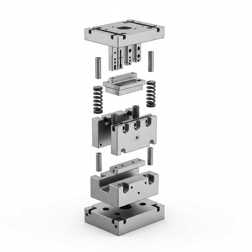
Katrs metāla stempļu veidgabala projekts balstās uz pamata komponentiem, kas darbojas kopā ar precīziem pieļaujamajiem noviržu lielumiem. Kad tu uzmanīgi aplūko stempļu veidgabalu, tu redzēsi šos būtiskos elementus:
Veidgabala komplekts (veidgabala pamatne): Šis ir jūsu visu stempļu matricu komponentu sistēmas pamats. Matrica sastāv no augšējās un apakšējās matricas zolītēm, kas nodrošina stingru montāžas platformu visiem pārējiem komponentiem. Bez pareizi izstrādātas matricas pat labākie urbja un matricas komponenti sniegs neatbilstošus rezultātus. Matrica absorbē un sadala milzīgās spēkas, kas rodas katrā preses gājienā.
Urbs un matricas bloks: Šie ir jūsu galvenie darba komponenti — daļas, kas faktiski griež, veido vai formas jūsu materiālu. Urbs ir vīrieša komponents, kas ar spēku nolaižas lejup, kamēr matricas bloks darbojas kā sievišķais pretparts. Kā norāda ražošanas speciālisti, urba un matricas starpība ir kritiska — tā nosaka gan griezuma kvalitāti, gan kopējo matricas veiktspēju. Nepareiza starpība ir viena no galvenajām iemeslu burvju veidošanās un pāragrā rīku nodilumā.
Noņemšanas plāksne: Vai jums kādreiz ir radies jautājums, kā detaļas pēc veidošanas viegli atdalās no urbja? To nodrošina atdalītājs. Šis ar atsperēm aprīkotais komponents stingri tur materiālu pret matricas presi griešanas vai veidošanas kustības laikā, pēc tam atbrīvo gatavo detaļu, kad urbis atgriežas atpakaļ. Pēc metālapstrādes ekspertu viedokļa, atdalītāji novērš detaļu pielipšanu pie urbja vai matricas, nodrošinot tīru izgrūšanu bez bojājumiem.
Vadpini un vadi: Precīza izlīdzināšana metālapstrādē ir nenovēršama prasība. Vadītājzīmuļi ir cilindriskas stieņveida daļas, kas nodrošina augšējās un apakšējās matricas zolītes ideālu paralēlumu visā darbības laikā. Vadiļas nodrošina gludu un kontrolētu kustību komponentiem matricā. Kopā tās saglabā precizitāti, kas novērš neatbilstības defektus.
Matricas atsperes: Šīs spirālveida atsperes nodrošina atgriezenisko spēku, kas nepieciešams kustīgu komponentu atiestatīšanai pēc katras gājiena. Pareiza atsperu izvēle ietekmē visu — no izstumtāja funkcijas līdz vadpina atgriešanai. Atsperes jākalibrē precīzi — pārāk vājas atsperes neļauj komponentiem pareizi atgriezties; pārāk stipras atsperes rada pārmērīgu slodzi un ātrāku nodilumu.
Dizaina principi precīziem rezultātiem
Izpratne par apvedceļa iespiedumiem loksnes metāla formēšanā atklāj vienu no mazāk zināmajiem dizaina principiem, kas atšķir labus matricu veidus no lieliskiem. Apvedceļa iespiedumi ir stratēģiski novietoti atvieglojuma griezumi, kas ļauj materiālam plūst gludi formēšanas operāciju laikā. Tie novērš materiāla pieķeršanos, samazina formēšanas spēkus un novērš rievu veidošanos sarežģītās ģeometrijās. Kad inženieri izlaiž šo dizaina elementu, bieži vien kvalitātes problēmas tiek konstatētas tikai pēc ražošanas uzsākšanas.
Kādi dizaina apsvērumi jāņem vērā, izstrādājot jūsu stempļu matricas? Koncentrējieties uz šiem būtiskajiem faktoriem:
- Atstatuma optimizācija: Atstarpe starp urbīšanu un matricu parasti ir 5–10 % no materiāla biezuma griešanas operācijām — pielāgojiet atkarībā no materiāla cietības un vēlamās malas kvalitātes
- Materiāla plūsmas plānošana: Veidojiet formēšanas stacijas tā, lai pakāpeniski vadītu materiālu, izvairoties no pēkšņām deformācijām, kas izraisa plaisas vai pārrāvumus
- Atspirgšanas kompensācija: Nelielā mērā pārlieku lieciet formēšanas elementus, lai kompensētu materiāla elastīgo atjaunošanos, īpaši augstas stiprības tēraudā un nerūsējošajos sakausējumos
- Vadpilota novietojums: Novietojiet vadpilotus, lai precīzi kontrolētu lentes progresiju un novērstu staciju nesakritību progresīvajās matricās
- Smērvielas kanāli: Iekļaujiet ceļus smērvielas sadalei uz augstas berzes zonām, lai pagarinātu matricas kalpošanas laiku un uzlabotu virsmas apdari
- Pieejamība apkopei: Projektējiet matricas komponentus tā, lai tos būtu viegli noņemt un nomainīt, samazinot darba pārtraukumus asināšanas un remontdarbu laikā
Mūsdienu CAE simulācija ir pārvērtusi to, kā inženieri pieejas metāla stempelēšanas matricu projektēšanai. Saskaņā ar pētījums, kas publicēts ScienceDirect , CAE simulācijas tehnoloģija palīdz speciālistiem izveidot, pārbaudīt, validēt un optimizēt dizaina risinājumus. Pašlaik ražošanā produktu izstrāde pāriet no tradicionālās mēģinājumu un kļūdu metodes uz pierādījumiem balstītu koncepciju, kas balstīta uz CAE atbalstītām simulācijām.
Ko tas praktiski nozīmē? Inženieri tagad var simulēt materiāla plūsmu, prognozēt defektu atrašanās vietas un optimizēt matricas ģeometriju, pirms tiek sagriezts jebkāds tērauds. Pētījums parāda, ka, salīdzinot simulācijas rezultātus vairākos dizaina variantos, var identificēt optimālos izkārtojumus — samazinot dārgos fiziskos prototipus un paātrinot laiku līdz ražošanas uzsākšanai.
Kā norāda uzņēmums Approved Sheet Metal, formas programmatūra var analizēt detaļu formas, lai nodrošinātu pareizās matricas konfigurācijas izvēli. Šī iespēja ir īpaši vērtīga sarežģītām ģeometrijām, kur tradicionālais pieredzes pamatā balstītais dizains var neievērot būtiskus jautājumus.
Ievērojiet pieļaujamās novirzes kumulāciju savā matricas projektēšanas procesā. Katra liekšana un formēšanas stacija ievada novirzi, un šīs novirzes kumulējas vairākos apstrādes posmos. Projektējot ar realistiskām pieļaujamām novirzēm — stingrākām tikai tur, kur tas ir funkcionāli būtiski — tiek novērstas ražošanas grūtības, vienlaikus kontrolējot izmaksas. Izmantojot vispārpieņemtus liekšanas rādiusus, kas atbilst pieejamajiem rīkiem, tālāk samazinās uzstādīšanas laiks un rīku izmaksas.
Ražotājiem, kuri meklē augstus pirmās pārbaudes apstiprinājuma rādītājus prasīgās automobiļu lietojumprogrammās, sadarbība ar matricu izgatavotājiem, kas izmanto modernas CAE simulācijas iespējas, nodrošina mērāmas priekšrocības. IATF 16949 sertificēti ražotāji apvieno simulācijām balstītu projektēšanu ar precīzu izgatavošanu, lai sasniegtu bezdefektu rezultātus — pārvēršot projektēšanas lēmumus par vienveidīgu ražošanas kvalitāti.
Jūsu matricas konstrukcijas izvēle tieši nosaka turpmākos rezultātus. Pareiza komponentu izvēle, rūpīga materiāla plūsmas plānošana un simulācijām apstiprināta ģeometrija veido pamatu 80 % defektiem, kurus patiešām var novērst. Kad stingri konstrukcijas pamatprincipi ir noteikti, jūs esat gatavs risināt problēmas, ja tās tomēr rodas, — kā arī to, kā tās atklāt pirms tās nonāk pie jūsu klientiem.
Defektu novēršana un kvalitātes kontroles metodes
Šeit ir neērīgā patiesība par ražošanas stempelēšanas procesu: lielākā daļa kvalitātes problēmu rodas pašiem sev. Kad jūs saprotat, kas izraisa defektus matricu stempelēšanas operācijās, jūs iegūstat spēku tos novērst. Labā ziņa? Industrijas dati liecina, ka aptuveni 80 % stempelēto detaļu defektu ir saistīti ar identificējamām, novēršamām pamatcēlonēm.
Vai nu jūs novēršat problēmas ar uzpūtām malām uz nupat stempļotām detaļām, vai arī pētāt izmēru nobīdi ražošanas procesā — šajā sadaļā sniegts diagnostikas rāmis un profilakses stratēģijas, kas atšķir augstas iznākuma darbības no tām, kurām pastāvīgi jācīnās ar kvalitātes problēmām.
Bieži sastopamo stempļošanas defektu identifikācija
Katrs defekts stāsta stāstu par to, kas ražošanas laikā nogājis greizi. Saskaņā ar DGMF Mold Clamps, lietošanā esošajiem stempļošanas matricu veidgabaliem ir raksturīga dažāda nodiluma pakāpe katrā urbuma kodola sānu pozīcijā, un dažas detaļas rāda lielākas skrāpējumu pēdas un nodilst ātrāk — īpaši izteikts tievos un šaurajos taisnstūrveida matricu veidgabalos. Šo modeli saprotot, var ieviest korektīvas darbības, pirms nelielas problēmas kļūst par nopietnām kvalitātes problēmām.
Apskatīsim biežāk sastopamos defektus, kas rodas stempļotām detaļām:
Uzpūtām malām: Tie uzraušanās rezultātā radušies, neapstrādātie malu izvirzījumi pa griezuma līnijām, kas var sagriezt pirkstus un ievainot savienojamo virsmu. Skalves veidojas, ja punch-die atstarpe ir nepareiza vai ja griezuma malas kļūst bluntas. Pārmērīgas skalves norāda, ka pienācis laiks pārbaudīt jūsu rīku.
Plaisas: Materiāls plīst deformācijas operāciju laikā, parasti redzams liekuma līnijās vai velkšanas locījuma rādiusos. Plaisas norāda, ka jūs pārsniedzat materiāla deformējamības robežas — vai nu pārmērīgas deformācijas dēļ, nepietiekami liela liekuma rādiusa dēļ vai tāpēc, ka materiāls ir kļuvis stingrāks un zaudējis savu izstiepjamību.
Ripas: Viļņveidīgas, izliektas virsmas, kas parādās velkšanas operāciju laikā, kad spiedes spriegumi pārsniedz materiāla stabilitāti. Vismazākās vilnas bieži redzamas malu apvītās (flanged) vietās vai dziļi velktās detaļās, kur materiāla plūsma nav pareizi kontrolēta.
Atsperošana: Elastīgā atjaunošanās, kas izraisa saliektu detaļu daļēju iztaisnošanos pēc formas veidošanas. Katrs materiāls parāda kādu līmeni elastīgās atjaunošanās, taču augstas izturības tēraudi un nerūsējošās sakausējumu sakausējumi ir īpaši problēmiski. Neizlabota elastīgā atjaunošanās noved pie detaļām, kas neatbilst norādītajām precizitātes robežām, un montāžas problēmām.
Izmēru neprecizitāte: Detaļas, kas neatbilst norādītajām precizitātes robežām, kaut arī vizuāli izskatās pieņemamas. Saskaņā ar Metal Infinity , izmēru precizitāte stempelētām detaļām parasti ir aptuveni ±0,05 mm — tas atbilst divu A4 formāta papīra lapu biezumam. Bez kontroles mehānisma šis niecīgais novirzes lielums var izraisīt montāžas problēmas, nevienmērīgi ievietotus skrūvju savienojumus vai pat aprīkojuma bloķēšanos.
| Defekta veids | Galvenie cēloņi | Korekcijas pasākumi | Novēršanas stratēģija |
|---|---|---|---|
| Malu apstrāde (burrs) | Noasinātas griezējmalas; nepareiza puncera un matricas attāluma starpība; nodiluši vadītājpini | Noasināt vai nomainīt rīkus; pielāgot attāluma starpību līdz 5–10 % no materiāla biezuma; nomainīt nodilušos vadītājpini | Plānotas asināšanas intervālu ievērošana; attāluma starpības pārbaude uzstādīšanas laikā; regulāras izlīdzināšanas pārbaudes |
| Sprādzieni | Pārāk mazs liekšanas rādiuss; pārmērīga deformācijas slodze; materiāla cietināšanās deformācijas rezultātā | Palielināt liekšanas rādiusus; pievienot veidošanas posmus; atkausēt materiālu starp operācijām | Dizaina validācija, izmantojot CAE simulāciju; materiāla formējamības testēšana; pareiza operāciju secība |
| Viegošana | Nepietiekams blanks turētāja spiediens; nepareiza materiāla plūsma; pārmērīgs atstarpe vilkšanas matricās | Palielināt blanks turētāja spēku; pievienot vilkšanas ripas; samazināt matricas atstarpi | Optimizēts blanks turētāja dizains; simulācijās validēti vilkšanas parametri |
| Atsperošana | Materiāla elastīgā atjaunošanās; nepietiekama pārliektas leņķa kompensācija; neatbilstošas materiāla īpašības | Palielināt pārliektas leņķa lielumu; pievienot monētu veidošanas vai atkārtotas veidošanas operācijas; pielāgot veidošanas spiedienu | Materiālam specifiski kompensācijas koeficienti; simulācijās balstīts matricu dizains |
| Neprecīzas dimensijas | Matricu nodilums; termiskā izplešanās; materiāla svārstības; vadītāju noregulēšanas kļūda | Izmērīt un pielāgot matricu komponentus; pārbaudīt vadītāju novietojumu; stingrāk noteikt materiāla specifikācijas | Statistikas procesa vadība; regulāra matricu pārbaude; ieejošo materiālu verifikācija |
| Virsmas svītras | Uz matricām esošs netīrumu nogulsnes; nepietiekama smērvielu pielietošana; raupji matricu virsmas | Rūpīgi notīrīt matricas; palielināt smērvielu pielietošanu; polirēt kontaktvirsmas | Regulārs matricu tīrīšanas grafiks; smērvielu uzraudzība; aizsargpārklājumi uz matricām |
Preventīvās stratēģijas kvalitatīvu detaļu ražošanai
Defektu novēršana sākas daudz agrāk nekā detaļas nonāk galīgajā pārbaudē. Kā uzsver Metal Infinity, kvalitātes pārbaude nav tikai defektīvu izstrādājumu izvēle — tā ir būtiska pamatne datu savākšanai, problēmu identificēšanai un ražošanas procesa uzlabošanai.
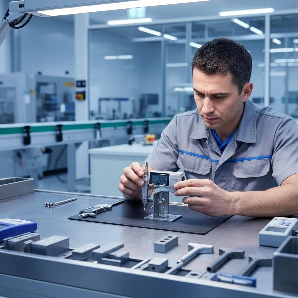
Efektīva kvalitātes kontrole precīzijas matricām un stempelēšanas operācijām balstās uz vairāku posmu pieeju:
Ienākošo materiālu inspekcija: Jūsu pirmā aizsardzības līnija. Pārbaudiet, vai loksnes biezums atbilst specifikācijām — saskaņā ar nozares standartiem atļautās novirzes var būt ±0,05 mm standarta lietojumiem vai ±0,03 mm augstas precizitātes prasībām. Pirms materiāla ievadīšanas ražošanā pārbaudiet rievas, oksidāciju un deformācijas.
Pirmā izstrādājuma pārbaude: Pirms katras ražošanas partijas izgatavojiet parauga detaļu un pārbaudiet tās izmērus, izskatu un funkcionalitāti. Masveida ražošana var sākties tikai pēc apstiprinājuma. Šī vienkāršā prakse ļauj noteikt uzstādīšanas kļūdas, pirms tās kļūst par visai partijai raksturīgām problēmām.
Ražošanas procesa laikā veicamās patrulēšanas pārbaudes: Regulāra paraugu ņemšana ražošanas laikā — piemēram, ik pēc 30 minūtēm pārbaudot piecas detaļas — nodrošina procesa stabilitāti. Kvalitātes eksperti norāda, ka patrulēšanas pārbaudes ļauj noteikt problēmas, piemēram, pakāpenisku izmēru nobīdi, ko izraisa matricas nodilums, pirms tās ietekmē lielu detaļu skaitu.
Uzspiedumu detaļām galvenās pārbaudes metodes:
- Vernjera kalibrētāji un biezuma mērītāji izmēru verifikācijai (precizitāte līdz ±0,01 mm)
- 2,5D mēraparāti precīziem caurumu novietojumiem un sarežģītām ģeometrijām
- Mikroskopi plaisu, uzpūtumu un virsmas defektu noteikšanai, kurus nevar redzēt ar neapbruņotu aci
- Taktilie mērījumu rīki plaknuma un izliekuma stāvokļa pārbaudei
- Specializēti stiprinājumi funkcionalitātes testēšanai — liektu detaļu, aizbīdņu un montāžas savienojuma piemērotībai
Matricu nodiluma raksti un to ietekme uz kvalitāti
Matricu nodiluma izpratne palīdz prognozēt brīdi, kad kvalitāte sāks pasliktināties. Saskaņā ar Keneng Hardware matricu nodilums rodas kā rezultāts atkārtotajam kontaktam starp matricas virsmu un metāla blīvējamo materiālu, pie kam vairāki faktori veicina galīgo atteici.
Biežāk novērojamie nodiluma raksti, kurus jāuzrauga:
- Adhezīvs nodilums: Materiāla pārnešana starp matricu un apstrādājamo detaļu, kas rada gallingu un raupju virsmu
- Abrazīvs nodilums: Griešanas malu pakāpeniska iznīcināšanās, kas izraisa uzpūtumu veidošanās palielināšanos
- Uzliesmošanas nodilums: Mikro krakšana no atkārtotiem stresa cikliem, kas galu galā rada izskalojumus vai lūzes
- Nevienlīdzīgs notekūdeņi: Nepareiza izredze, kas izraisa vienu punkcijas pusi ātrāk nekā otru
Kā konstatēja problēmu risināšanas eksperti, nevienlīdzīga izkārnījuma apģērbs bieži rodas, jo torņa izkārnījums ir slikts, izkārnījuma precizitāte nav pietiekama vai izkārnījuma izkārnījumu izvēle nav pareiza. Lai novērstu šo slimību, ir vajadzīgas regulāras izšķiršanas pārbaudes, savlaicīga vadlīniju apvalku nomaiņa un precīzu lietojumu nodrošināšanai pilnvērtīgi vadlīniju izstrādes.
Pareiza stūres apkope novērš kvalitātes problēmas
Jūsu metāla metāla metāla metāla metāla metāla metāla metāla metāla metāla metāla metāla metāla metāla metāla metāla metāla metāla metāla metāla metāla metāla metāla metāla metāla metāla metāla metāla metāla metāla metāla metāla metāla metāla metāla metāla metāla metāla met Saistība starp tehniskās apkopes un kvalitātes nodrošināšanu ir tieša. Izmantojiet šādas prakses:
- Lai noteiktu aizkavēšanas intervālus, pamatojoties uz materiāla veidu un ražošanas apjomu
- Pēc katra ražošanas posma pārbauda griezuma malas, lai palielinātu to
- Periodiski pārbauda caurulēm no perforācijas līdz izkārnījumiem, izmantojot izkārnījumu mērītājus vai mērīšanas instrumentus.
- Tīriet matricas rūpīgi starp katru darbības ciklu, lai noņemtu netīrumus un uzkrājušos materiālu
- Reģistrējiet nodiluma novērojumus, lai izveidotu prognozējošās apkopes pamatvērtības
Piemērs ilustrē riskus: viens ražotājs, kas ražo automašīnu TFT-LCD balstus, patrulēšanas pārbaudē atklāja, ka izmēri pakāpeniski palielinās. Izmeklēšana apstiprināja matricas vadītājstabu nodilumu. Bez procesa laikā veiktās kvalitātes kontroles varētu būt jāizmet visu 20 000 detaļu partija. Tomēr, tā kā pārbaude to atklāja laikā, tika zaudēti tikai 200 gabali — zaudējumi tika dramatiski samazināti.
Kvalitātes kontrole metāla stempelēšanas ražošanas procesā nav izmaksu centrs—tā ir jūsu apdrošināšanas polise pret daudz lielākām zaudējumiem. Apvienojot sistēmisku pārbaudi, nodiluma raksturlielumu izpratni un proaktīvu apkopi, jūs pārvēršat kvalitāti no reaģējošas krīzes novēršanas par konkurences priekšrocību. Kad defektu novēršana ir apgūta, nākamais solis ir saprast, kā pareizi izstrādātas apkopes grafiki maksimāli palielina jūsu matricu ieguldījumu laika gaitā.
Matricu apkope un ilgmūžības labākās prakses
Jūs esat ieguldījuši tūkstošus—reizēm desmitus tūkstošu—dolāru savās stempelēšanas matricās. Tomēr šo daudzi ražotāji ignorē: šis ieguldījums sāk deprecēties jau tad, kad jūsu matricas nonāk ražošanā bez pienācīgas apkopes stratēģijas. Saskaņā ar Phoenix Group ekspertiem , nepietiekami definēta matricu veikala pārvaldības sistēma var dramatiski samazināt preses līnijas ražīgumu un palielināt izmaksas.
Sakarība starp metāla stempļu veidņu apkopi un detaļu kvalitāti nav tikai teorētiska. Nepietiekama veidņu apkope rada kvalitātes defektus ražošanas laikā, palielina klasifikācijas izmaksas, palielina defektīvu detaļu nosūtīšanas varbūtību un rada risku saistībā ar dārgām piespiedu ierobežošanas pasākumiem. Apskatīsim, kā sistēmiska apkope pārvērš jūsu stempļu veidnes no riska faktora ilgtermiņa aktīvā parastās vērtībā.
Profilakses uzturēšanas grafiki
Uztveriet profilaktisko apkopi kā savu apdrošināšanas polisi pret negaidītu darbības pārtraukumu. Nevis gaidot, kad veidnes pilnībā atsakās, jūs risināt potenciālas problēmas kontrolētos intervālos. Saskaņā ar JV Manufacturing, profilaktiskās apkopes grafiki ļauj darbiniekiem novērst nelielas problēmas plānotajos darbības pārtraukumos, nevis ražošanas laikā — nodrošinot nepārtrauktu darba procesu.
Cik bieži jums vajadzētu apkopt savas stempļu veidnes? Tas ir atkarīgs no vairākiem faktoriem, kas darbojas kopā:
- Ražošanas apjoms: Augsta apjoma ražošanas cikli prasa biežāku veidgabalu pārbaudes ciklu — apsveriet iespēju pārbaudīt veidgabalus katrās 50 000–100 000 darbībās pie slodzes lietojumiem
- Materiāla cietība: Nestilīga tērauda vai augstas izturības sakausējumu stempelēšana paātrina nodilumu salīdzinājumā ar mīksto tēraudu vai alumīniju, tādēļ nepieciešami īsāki tehniskās apkopes intervāli
- Detaļas sarežģītība: Progresīvie veidgabali ar vairākām stacijām prasa lielāku uzmanību nekā vienkāršie izgriezuma veidgabali
- Vēsturiskie dati: Uzraudziet nodiluma raksturus laika gaitā, lai izveidotu prognozējamus pamatindeksus, kas specifiski attiecas uz katru veidgabalu
Jūsu tehniskās apkopes pārbaudes saraksts ir jāiekļauj šādas būtiskās darbības:
- Vizuālā inspekcija: Pārbaudiet griezuma malas, veidošanas virsmas un vadības komponentus redzamam nodilumam, plaisām vai bojājumiem
- Izmēru verifikācija: Izmēriet urbja un veidgabala atstarpi, izmantojot plākšņu mērītājus; pārliecinieties, ka tā paliek ietvaros 5–10 % no materiāla biezuma griešanas operācijām
- Asināšanas novērtējums: Apskatiet griezuma malas zem palielinājuma — bluntais griezums rada uzrauļus un prasa nekavējoties veikt korekcijas
- Veseru izmēģinājumi: Pārbaudiet, vai matricas veseri saglabā pareizo spēku; vājināti veseri izraisa izstumšanas kļūmes un detaļu bojājumus
- Izlīdzināšanas pārbaude: Apstipriniet, ka vadības stieņi un ieliktņi saglabā precīzu izlīdzinājumu bez pārmērīgas kustības
- Smērvielu pārbaude: Pārliecinieties, ka visiem kustīgajiem komponentiem tiek nodrošināta pietiekama smērviela, lai novērstu saķībēšanos un ātro nodilumu
- Dokumentācija: Ierakstiet visas novērojumus matricu apkopēs uz matricu apkopes kartītēm nākotnes atsauces un tendenču analīzei
Saskaņā ar Manor Tool, pēc pārbaudes pabeigšanas jāaizpilda matricu apkopes kartīte ar visu veikto darbu, jāmarķē pārbaudītā rīka vienība un jāpasūta visi nepieciešamie aizvietošanas komponenti. Šī dokumentācija kļūst neaizstājama nākotnes apkopju vajadzību prognozēšanai.
Matricu kalpošanas laika maksimālā palielināšana
Pietiekama smērvielu pieteikšana ir tikpat svarīga kā asināšana metāla stempļu rīku kalpošanas laika pagarināšanai. Kā norāda nozares eksperti, smērvielas samazina berzi starp virsmām, novēršot pārmērīgu siltuma veidošanos, kas var izraisīt materiāla izturības zudumu un atteici. Tās arī aizsargā pret koroziju un kaitīgu elementu iekļūšanu.
Izvēlieties smērvielu tipu atbilstoši jūsu lietojumam:
- Eļļas smēršana: Vispiemērotākā augsta ātruma darbībām un hidrauliskajām sistēmām
- Smērvielu maisījums (želeja): Ideāls gultņiem, savienojumiem un lietojumiem, kur šķidrās smērvielas nav praktiskas
- Sauss smērvielu veids: Izmantojams tur, kur ir bīstama eļļas piesārņošana, piemēram, elektrisko komponentu ražošanā
Arī uzglabāšanas apstākļi ietekmē matricu kalpošanas ilgumu. Kad matricas nav ekspluatācijā:
- Uz visām atklātajām tērauda virsmām uzklājiet pretkorozijas aizsardzības pārklājumu
- Uzglabājiet klimatizētās telpās, ja iespējams, lai novērstu mitruma bojājumus
- Pareizi atbalstiet matricas, lai novērstu izkropļošanos vai deformāciju
- Turiet matricas apsegtas, lai novērstu putekļu un netīrumu uzkrāšanos
Kad jāatjauno, nevis jānomaina stempļu matricas? Apdomājiet šos lēmumu pieņemšanas faktorus:
- Atjaunojiet, ja: Nolietojums ierobežots ar griezējmalām un veidojošajām virsmām; pamatmatricas konstrukcija paliek stabila; izmēru precizitāti var atjaunot, izmantojot slīpēšanu un starplikas; remonta izmaksas ir mazākas par 40–50 % no jaunas matricas iegādes izmaksām
- Nomainiet, ja: Konstrukcijas komponentos redzamas noguruma plaisas; vairākās stacijās vienlaikus nepieciešami lieli remonti; matricas dizains ir novecojis un izraisa atkārtotas kvalitātes problēmas; kopējās remonta izmaksas tuvojas jaunas matricas vērtībai
Saskaņā ar Phoenix Group datu no iepriekšējiem darba uzdevumiem var izmantot, lai uzlabotu preventīvās apkopes plānus un grafikus visām daļu grupām. Sekojot remonta biežumam un bojājumu veidiem, jūs attīstīsit prognozējošās spējas, kas novērš problēmas pirms tās traucē ražošanu.
Galvenais secinājums? Jūsu matricu ražošanas ieguldījumu regulārā apkope dod peļņu, samazinot atkritumu daudzumu, ārkārtas remontus un nodrošinot paredzamu ražošanas kvalitāti. Kad jūsu apkopes stratēģija ir noteikta, jūs esat gatavs novērtēt, kad stempelēšana joprojām ir jūsu labākā ražošanas izvēle — un kad alternatīvas metodes varētu kalpot jums labāk.
Matricu stempelēšana pret citām ražošanas metodēm
Jūs esat apguvuši matricu izvēli, materiālus, operācijas un apkopi—bet šeit ir jautājums, kas sagādā grūtības pat pieredzējušiem iepirkumu speciālistiem: kad jāizmanto metāla stempelēšana salīdzinājumā ar citām ražošanas metodēm? Nepareizas metodes izvēle var nozīmēt pārmaksu par 40 % vai vairāk, ilgāku gaidīšanu par nedēļām, nekā nepieciešams, vai arī spiesties apmierināties ar zemākas kvalitātes detaļām.
Patiesībā stempelēšana nav vienmēr pareizais risinājums. Izpratne par to, kur matricu griešana un stempelēšana ir efektīvākas—un kur alternatīvas metodes tās pārspēj,—palīdz jums pieņemt lēmumus, kas vienlaikus optimizē izmaksas, kvalitāti un termiņus.
Gadījumi, kad stempelēšana pārspēj alternatīvas
Metāla stempelēšana dominē lielapjoma ražošanā ar labu iemeslu. Saskaņā ar Hotean ražošanas analīzi , stempelēšanas priekšrocība uz vienu vienību kļūst būtiska, tiklīdz tiek pārsniegti noteikti apjomu sliekšņi—parasti aptuveni 3000–10 000 vienības, atkarībā no detaļas sarežģītības.
Kas padara metāla stempelēšanu neaizstājamu lielos apjomos? Vairāki faktori savstarpēji pastiprina jūsu priekšrocības:
- Ātrums: Preses izgatavo 600 līdz 2400 detaļas stundā, pārspējot citus ražošanas paņēmienus
- Konsekvens: Matricās veidotās detaļas saglabā precīzus izmērus miljoniem ciklu laikā
- Materiālu efektivitāte: Progresīvās matricas minimizē atkritumus, optimizējot detaļu izvietojumu (nesting)
- Darba izmaksas: Automatizēta ievade un izvade dramatiski samazina darba izmaksas uz vienu detaļu
Apsveriet šo salīdzinājumu: preses operācija, kas darbojas ar 600 gāzieniem stundā, vienā stundā var izgatavot tik daudz detaļu, cik nepieciešams mēneša ražošanai daudzām lietojumprogrammām. Šādu ražīgumu vienkārši nevar sasniegt ar griešanai balstītām tehnoloģijām.
Tomēr presēšanai ir nepieciešama ievērojama sākotnējā investīcija. Saskaņā ar MIT pētījumu par automašīnu presēšanas izmaksām , rīku izmaksas presētajām komplektām veido būtiskas kapitāla izmaksas, kuras jāsadala pa ražošanas apjomu. Tieši šeit kritiski svarīgi ir saprast bezpeļņas punktus.
Pareizā ražošanas metodes izvēle
Tātad kā izvēlēties starp stemplošanu, lāzera griešanu, CNC apstrādi, ūdensstrūkas griešanu vai pievienojošo ražošanu? Katra metode atbilst atsevišķām vajadzībām, kas saistītas ar daudzumu, sarežģītību un materiālu spektru.
Lasera gaļas segšana: Ja jūs pārdomājat, kā griezt tērauda loksnes prototipu daudzumiem vai nelielām partijām, lāzera griešana piedāvā ievērojamus priekšrocības. Saskaņā ar ražošanas izmaksu analīzi, lāzera griešana nodrošina 40 % izmaksu samazinājumu salīdzinājumā ar stemplošanu partijām, kas ir mazākas par 3000 vienībām, jo tiek novērstas rīku izmaksas, kas pārsniedz 15 000 USD. Šī tehnoloģija sasniedz precizitāti ±0,1 mm salīdzinājumā ar stemplošanas tipisko precizitāti ±0,3 mm — un ražošana var sākties jau 24 stundu laikā pēc digitālo failu saņemšanas.
CNC apstrāde: Kad jūsu detaļām nepieciešamas trīsdimensiju funkcijas, stingras pieļaujamās novirzes vai cieti materiāli, CNC apstrāde aizpilda tukšumus, kurus stemplošana nevar novērst. Tā īpaši piemērota prototipiem, nelielām partijām un detaļām, kurām nepieciešamas funkcijas vairākos virsmas pusēs. Tomēr katras detaļas izmaksas paliek augstas neatkarīgi no ražošanas apjoma.
Ūdensstrūklas griešana: Šis aukstā griešanas process apstrādā gandrīz jebkuru materiālu bez siltuma ietekmētām zonām — ideāli piemērots siltumjūtīgiem sakausējumiem vai kompozītmateriāliem. Ūdensstrūkas griešana labi darbojas vidēja biezuma materiāliem, kur termiskās deformācijas nav pieļaujamas, taču lēnāks griešanas ātrums ierobežo ražošanas jaudu.
Pievienojošā ražošana: Metāla 3D drukāšana ļauj izgatavot ģeometrijas, kas ir neiespējamas ar jebkuru atņemošo vai formēšanas procesu. Saskaņā ar Protolabs ražošanas norādījumiem tiešā metāla lāzera sintēze (DMLS) veido detaļas slānis pēc slāņa, sasniedzot precizitāti ±0,003 collas un elementus, kas mazāki par punktu. Tomēr ražošanas ātrums un izmaksas šo tehnoloģiju ierobežo līdz prototipiem, nelielām partijām un ļoti sarežģītām detaļām.
Rūpnieciska matricu griešanas mašīna vai matricu griezējs metāla lietojumiem daļēji aizpilda šo spraugu — nodrošinot ātrāku uzstādīšanu nekā tradicionālās stempļu matricas, vienlaikus apstrādājot vidējas partijas ekonomiskāk nekā lāzera griešana. Matricu griešanas mašīna īpaši labi darbojas ar mīkstākiem materiāliem un vienkāršākām ģeometrijām.
| Iemesls | Iestampēšanas veidņos | Lāzera griešana | CNC apstrāde | Ūdens strūklas | Pievienojošais (DMLS) |
|---|---|---|---|---|---|
| Ideālais apjoma diapazons | 10 000+ vienības | 1–3000 vienības | 1 - 500 vienības | 1–1000 vienības | 1 - 100 vienības |
| Daļas sarežģītība | Augsts (2D ar veidošanu) | Vidējs (2D profili) | Ļoti augsts (3D elementi) | Vidējs (2D profili) | Ekstremāls (organiskas formas) |
| Materiāla varianti | Loksnes metāli līdz 0,5 collām | Metāli līdz 1 collai; plastmasas | Gandrīz visi metāli/plastmasas | Jebkura materiāla izstrādājumi līdz 6 collām | Izvēlēti metāli/sakausējumi |
| Vienības izmaksas pie 100 gabaliem | Ļoti augsts (rīku izmaksas) | Zema-Vidēja | Augsta | VIDĒJS | Ļoti augsts |
| Vienības izmaksas pie 10 000 gabaliem | Ļoti zems | VIDĒJS | Augsta | Vidējs-Augsts | Nepiemērots |
| Parastā atļauja | ±0,1 - 0,3 mm | ±0,1 mm | ±0.025mm | ±0,1–0,2 mm | ±0,08 mm |
| Izpildes laiks (pirmās detaļas) | 4–8 nedēļas (rīku izgatavošana) | 24-48 stundas | 1-5 dienas | 1-3 dienas | 3-7 dienas |
| Izveidošanas/apstrādes izmaksas | 10 000–50 000+ USD | Nav (digitāli) | Minimāls (fiksēšanas ierīces) | Nav (digitāli) | Nav (digitāli) |
Izprast bezpeļņas punktus
Būtiskais jautājums nav tas, kura metode ir «labākā», bet gan kur krustojas izmaksu līknes. Saskaņā ar ražošanas izmaksu pētījumiem, presēšana parasti kļūst izdevīga, kad:
- Vienkāršas detaļas: Bezpeļņas apjoms aptuveni 3000–5000 vienības
- Vidējas sarežģītības detaļas: Bezpeļņas apjoms aptuveni 5000–10 000 vienības
- Sarežģītas progresīvās matricas detaļas: Bezpeļņas apjoms aptuveni 10 000–25 000 vienības
Šie sliekšņi mainās atkarībā no veidošanas rīku izmaksām, materiāla veida un detaļas izmēriem. Detalizēta izmaksu analīze no ražošanas ekspertiem parāda, ka lāzeru griešanas vidējās izmaksas ir 8,50 USD par vienību, salīdzinot ar stempelēšanu — 14,20 USD par vienību mazām partijām; tomēr šie skaitļi diametrāli mainās lielos apjomos, kad stempelēšanas veidošanas rīku ieguldījuma izmaksas tiek sadalītas pa daudzām detaļām.
Novērtējot savas iespējas, ņemiet vērā šo lēmumu pieņemšanas shēmu:
- Izvēlieties spiešanu, kad: Ražošanas apjomi pārsniedz 10 000 vienības; detaļas ģeometrija piemērota veidošanas operācijām; materiāla biezums ir zem 6 mm; jums ir prognozējams ilgtermiņa pieprasījums; detaļas izmaksas par vienu vienību ir galvenais faktors
- Izvēlieties lāzera griešanu, kad: Apjomi paliek zem 3000 vienībām; jums nepieciešama ātra prototipēšanas spēja; dizaini bieži mainās; precizitātes prasības ir stingras (±0,1 mm); termiņš ir steidzams
- Izvēlieties CNC apstrādi, kad: Detaļām nepieciešamas 3D funkcijas; pieļaujamās novirzes ir ļoti stingras; materiāls ir grūti apstrādāms; daudzumi ir ļoti mazi
- Izvēlieties ūdensstrūklas griešanu, kad: Siltuma izkropļojums nav pieļaujams; materiāli ir eksotiski vai kompozītmateriāli; vidēja precizitāte ir pietiekama
- Izvēlieties pievienojošo ražošanu, ja: Ģeometrija ir neiespējama izveidot vai apstrādāt ar mašīnām; svara optimizācijai nepieciešami iekšēji režģi; daudzumi ir minimāli
Ražošanas ainava turpina mainīties uz mazāku partiju lielumu un ātrākām iterācijas ciklu ilgumā. Dažādām lietojumprogrammām vislabāk der hibrīdpieeja — lāzeru griešana prototipiem un sākotnējai ražošanai, pārejot uz presēšanu, kad ražošanas apjomi attaisno rīku ieguldījumu. Šo kompromisu izpratne ļauj jums optimizēt gan izmaksas, gan termiņus visā jūsu produkta dzīvesciklā.
Kad ražošanas metodes izvēle ir skaidri noteikta, pēdējais uzdevuma gabaliņš ir saprast, kā šīs procesu metodes tiek piemērotas vienai no visprasašākajām nozarēm — automašīnu ražošanai, kur augstās kvalitātes prasības un lielie apjomi stumda matricu un stempļu iespējas līdz to robežai.
Automobiļu matricu un stempļu pielietojums
Automobiļu rūpniecība ir galīgā pārbaudes vieta matricu un stempļu izcilībai. Kad jūs ražojat metāla stempļu detaļas, kas paredzētas transportlīdzekļiem, kuri brauc ātrumā pa autoceļu, pārvadā pasažierus un darbojas ekstrēmos apstākļos, kvalitāte nav neobligāta — tā ir dzīvībai būtiska. Tāpēc automobiļu stempļu matricām ir visprasašākās specifikācijas visā ražošanas pasaulē.
Ievērojiet mērogu: saskaņā ar LMC Industries vidējais automobilis sastāv no aptuveni 30 000 komponentiem. No šīm detaļām ievērojama daļa — sākot no strukturālajām skavām līdz redzamajām ķermeņa panelēm — balstās uz stempelēšanas ražošanas procesiem. Saprotot, kā šī nozare pielieto matricu un stempelēšanas principus, atklājas labākās prakses, kas piemērojamas visās nozarēs.
Atbilstība automobiļu kvalitātes standartiem
Ja jums reiz ir radusies doma, kāpēc automobiļu metāla detaļu stempelēšanai tiek pievērsta tik stingra uzmanība, to izskaidro IATF 16949 sertifikācija. Šis starptautiski atzītais standarts iet daudz tālāk par pamata kvalitātes pārvaldību — tas izveido rāmi defektu novēršanai pirms to rašanās.
Saskaņā ar OGS Industries, kamēr ISO 9001 koncentrējas uz klientu apmierinātību, IATF 16949 iet vēl tālāk, nodrošinot atbilstību resursu taupīšanas ražošanai, defektu novēršanai, noviržu novēršanai, atkritumu samazināšanai un uzņēmuma specifiskajām prasībām. Metāla detaļām, kas paredzētas stempelēšanai automobiļiem, tas nozīmē:
- Stabila kvalitāte: Ražošanas procesi tiek uzraudzīti un mērīti, lai maksimāli palielinātu ražīgumu un nodrošinātu vienotus rezultātus miljoniem detaļu gadījumā
- Samazināta produkta variācija: Pārskatīti un uzlaboti ražošanas procesi nodrošina, ka metāla komponenti vienmēr atbilst augstas veiktspējas transportlīdzekļu prasībām, neatkarīgi no to pielietojuma
- Defektu novēršana: Metāla apstrādes, ražošanas un saistīto pakalpojumu procesi ir pārbaudīti un pierādīti kā atbilstoši produktu drošības prasībām, samazinot neefektivitāti un minimizējot defektus
- Uzticama piegādes ķēde: Šis sertifikāts noteic standartu piegādātāju izvēlei, veidojot stiprākas un uzticamākas partnerattiecības
- Samazināti atkritumi: Optimizēti ražošanas procesi un uzlabotas pārvaldības sistēmas nodrošina infrastruktūru, lai minimizētu atkritumus un īstenotu vides iniciatīvas
OEM specifikācijas prasības pievieno vēl vienu sarežģītības līmeni. Katrs automašīnu ražotājs uztur savus patentētos standartus materiālu īpašībām, izmēru novirzēm, virsmas apdarei un funkcionālajai veiktspējai. Jūsu automašīnu stempļu matrica ir jāizgatavo detaļas, kas atbilst gan vispārējiem nozaru standartiem IATF 16949, gan konkrētajām OEM prasībām — vienlaikus un nepārtraukti.
Kādi komponenti balstās uz progresīvo automašīnu komponentu stempļu izgatavošanu? Saraksts aptver gandrīz katru transportlīdzekļa sistēmu:
- Korpusa paneļi: Durvis, kapuci, spārni un jumta sekcijas, kurām nepieciešama precīza piegulde un A klases virsmas apdare
- Struktūras komponenti: Grīdas plāksnes, šķērssavienojumi un pastiprinājumi, kas nodrošina sadurmes aizsardzību un riteņu balsta stingrību
- Izstrādājumu turētāji un balsti: Dzinēja balsti, suspensijas kronšteini un piedziņas ierīču balsti, kuriem nepieciešamas stingras izmēru novirzes un izturība pret izturības samazināšanos
- Šasijas komponenti: Vadības rokturi, rāmja sijas un apakšriteņu balsta komplekti, kuriem nepieciešama augsta izturība un izmēru stabilitāte
- Iekšējās stempļu detaļas: Sēdekļu rāmji, instrumentu panelu balsti un apdarei paredzētie kronšteini, kas līdzsvaro svara samazināšanu un izturību
- Degvielas sistēmas daļas: Tvertnes, pildīšanas kakli un balsti, kuriem nepieciešama cieša konstrukcija un korozijas izturība
No prototipēšanas līdz ražošanas apjomam
Automobiļu projektus nevar uzreiz pārvērst no idejas līdz miljona vienību ražošanai. Ceļš no sākotnējā dizaina līdz pilnmēroga stempelēšanas ražošanai ietver vairākas validācijas fāzes — katrā no tām ir iespēja novērst defektus, kas skar 80 % slikti pārvaldīto programmu.
Saskaņā ar Neway Precision inženieri izmanto modernas CAD programmatūras sistēmas detaļu modelēšanai un stempelēšanas procesa simulācijai, kas palīdz identificēt potenciālas problēmas jau pirms ražošanas uzsākšanas. Šis simulāciju pirmajā vietā pieeja ir pārvērtusi automobiļu matricu izstrādi no mēģinājumu un kļūdu metodes par paredzamu inženierzinātni.
Ātrās prototipēšanas fāze nosaka dizaina izpildāmību. Mūsdienu ražotāji var piegādāt sākotnējos prototipu komponentus dažu dienu laikā — nevis nedēļu — izmantojot mīksto rīku izgatavošanu vai citus alternatīvus procesus. Šis ātrums ļauj dizaina komandām pārbaudīt formas, piemērotības un funkcionalitātes atbilstību, pirms tiek veikti ieguldījumi ražošanas rīkos.
Rīku izstrādes fāze pārvērš apstiprinātos dizainus par ražošanai gataviem automašīnu stempļu matricām. Tieši šajā posmā inženieru sadarbības pierāda savu vērtību. Pēc nozares ekspertu viedokļa, sadarbība un skaidra komunikācija starp automašīnu ražotājiem un stempļu ražotājiem ir būtiska, lai pārvarētu grūtības un projektus turētu grafikā.
Šīs fāzes laikā bieži sastopamās problēmas ir:
- Sarežģītu komponentu ģeometriju vadība, kas prasa daudzposmu deformāciju
- Materiāla stipruma prasību līdzsvarošana pret formējamības robežām
- Virsmas apdarēs nepieciešamo standartu sasniegšana, saglabājot cikla laika mērķus
- Rīku izgatavošanas termiņu koordinācija ar transportlīdzekļa izlaišanas grafikiem
Ražošanas validācijas fāze pierāda, ka presēšanas matricas darbojas vienmērīgi ražošanas ātrumos un apjomos. Saskaņā ar ražošanas pētījumiem automašīnu presēšanā izmēru precizitāte bieži sasniedz ±0,01 mm kritiskajiem izmēriem — šis precizitātes līmenis prasa stingru procesa kontroli.
Šeit tiek nodrošinātas mērāmas priekšrocības, ko sniedz modernās CAE simulācijas iespējas. Kā skaidro Neway Precision, rīku izstrādes process var sasniegt efektivitāti, ražojot vairāk nekā 150 detaļas stundā, saglabājot ±0,01 mm izmēru precizitāti — to panāk, izmantojot modernu rīku konstrukciju, optimizētu materiālu izvēli un precīzu presēšanas parametru kontroli.
Pilna mēroga ražošana prasa ilgstošu veiktspēju simtiem tūkstošu vai pat miljoniem ciklu laikā. Automašīnu presēšanas matricai ir jāsaglabā izmēru precizitāte, virsmas kvalitāte un cikla ilguma vienmērīgums visā tās ekspluatācijas laikā. Tieši šeit preventīvās apkopes programmas un kvalitātes uzraudzības sistēmas pierāda savu vērtību.
Ražotājiem, kuri vēlas paātrināt automašīnu ražošanas termiņus, vienlaikus sasniedzot bezkļūdu rezultātus, sadarbība ar IATF 16949 sertificētiem piegādātājiem ar modernām CAE simulācijas iespējām ir pierādīts ceļš. No ātras prototipēšanas jau pēc 5 dienām līdz lielapjoma ražošanai ar 93 % pirmās apstiprināšanas likmi inženieru sadarbība, kas apvieno simulāciju vadītu projektēšanu un precīzu izgatavošanu, nodrošina kvalitātes standartus, kādus prasa automašīnu OEM ražotāji.
Automobiļu nozares nekompromisiskie standarti ir veicinājuši nepārtrauktu progresu matricu un stempļošanas tehnoloģijās. Šeit gūtās pieredzes vērtības — stingra procesu kontrole, simulācijām apstiprināta projektēšana, profilaktiska apkope un inženieru sadarbība — piemērojamas visās nozarēs, kurās stempļotiem komponentiem jāfunkcionē uzticami. Ieviešot šīs automobiļu nozares standarta prakses, jebkurš ražotājs var pievienoties tiem uzņēmumiem, kuros patiešām 80 % defekti ir novēršami.
Bieži uzdotie jautājumi par matricām un spiedformēm
1. Kāda ir atšķirība starp die cut un spiešanu?
Die cuttīngs un metāla stempelēšana ir atšķirīgi procesi ar dažādām lietojumprogrammām. Die cuttīngs parasti attiecas uz griešanas vai urbšanas operācijām, kurās materiāls tiek atdalīts, izmantojot asmalainus rīkus, radot plakanus profili vai formas. Metāla stempelēšana ietver plašāku aukstās formošanas operāciju klāstu, tostarp griešanu, liekšanu, velkšanu un monētu veidošanu, kas pārvērš plakanu loksnes metālu trīsdimensiju detaļās. Kamēr die cuttīngs koncentrējas uz 2D profila izveidi, stempelēšana apvieno vairākas operācijas, lai ražotu sarežģītas veidotās komponentes. Stempelēšanai izmanto progresīvus, pārneses vai saliktos matricas veidus kopā ar presēm, kas pieliek milzīgu spiedienu, lai precīzi veidotu metālu.
2. Kāda ir atšķirība starp die liešanu un stempelēšanu?
Spiedliešana un metāla stempelēšana pamatā atšķiras pēc procesa un pielietojuma. Spiedliešanā metāls tiek uzkarsēts līdz tā kausēšanās temperatūrai, un kausētais materiāls tiek iepildīts veidņos, lai izveidotu sarežģītas trīsdimensiju detaļas — ideāli piemērots sarežģītām ģeometrijām, taču prasa dārgas un ilgstošas veidnes. Metāla stempelēšana ir aukstā veidošanas metode, kurā izmanto loksnes metāla заготовки vai tinumus, kas tiek veidoti ar spiedienu bez uzkarsēšanas. Stempelēšana ir īpaši efektīva liela apjoma loksnes metāla komponentu ražošanai, nodrošinot ātrākus ciklus un zemākas vienības izmaksas masveida ražošanā. Spiedliešana piemērota sarežģītām liešanas ģeometrijām, bet stempelēšana ražo veidotās loksnes metāla detaļas, piemēram, skavas, paneļus un korpusus.
3. Kādi ir galvenie stempelēšanas veidņu tipi un kad katru no tiem vajadzētu izmantot?
Trīs galvenie matricu veidi apkalpo dažādas ražošanas vajadzības. Progresīvās matricas veic secīgas operācijas, kamēr metāls pārvietojas caur stacijām, un tās ir ideālas lielapjoma ražošanai — vairāk nekā 100 000 daļu gadā — ar materiāla biezumu no 0,005 līdz 0,250 collām. Pārvades matricas mehāniski pārvieto atsevišķas daļas starp stacijām, apstrādājot lielākas, sarežģītākas daļas un biezākus materiālus līdz 0,500 collām — tās piemērotas gadā ražotajam apjomam no 10 000 līdz 500 000 vienībām. Salikto matricu darbības tiek veiktas vienlaicīgi vienā kustībā, un tās ir vispiemērotākās vienkāršāku plakano daļu ražošanai ar augstu precizitāti — gadā ražojot no 5000 līdz 100 000 vienībām. Matricas izvēle ir atkarīga no daļas sarežģītības, ražošanas apjoma, materiāla biezuma un budžeta ierobežojumiem.
4. Kā novērst tipiskus defektus matricu stempelēšanas operācijās?
Izpilda defektu novēršana prasa sistēmisku pieeju visās projektēšanas, materiālu un procesa kontroles jomās. Novērsiet malu izvirzījumus (burring), uzturot pareizo atstarpi starp urbni un matricu — 5–10 % no materiāla biezuma — un noteiktu regulāras asināšanas grafiku. Novērsiet plaisas, izmantojot pietiekami lielus liekšanas rādiusus un validējot risinājumu ar CAE simulācijām. Kontrolējiet rievu veidošanos, optimizējot blanks turētāja spiedienu un izmantojot vilkšanas ribiņas. Kompensējiet atgriezenisko izliekumu (springback), pārliekot detaļas, ņemot vērā materiālam raksturīgos faktorus. Pirms ražošanas sērijas veiciet pirmā parauga inspekciju, laika gaitā ražošanas procesā — katru 30 minūti — veiciet patrulēšanas inspekcijas un uzturiet matricas saskaņā ar apjomam balstītu grafiku. IATF 16949 sertificētie ražotāji, ieviešot šīs prakses, sasniedz 93 % pirmās caurlaides apstiprināšanas likmi.
5. Kad matricu izstiepšana kļūst rentablāka par lāzeru griešanu?
Detaļu izgatavošana ar matricām kļūst rentabla dažādos apjomu sliekšņos atkarībā no detaļas sarežģītības. Vienkāršām detaļām bezpeļņas punkts rodas aptuveni pie 3000–5000 vienībām; vidējas sarežģītības detaļām bezpeļņas punkts ir pie 5000–10 000 vienībām; sarežģītām progresīvās matricas detaļām, lai attaisnotu rīku ieguldījumu, nepieciešami 10 000–25 000 vienību apjomi. Zem šiem sliekšņiem lāzeru griešana nodrošina 40 % izmaksu ietaupījumu, novēršot rīku izmaksas, kas pārsniedz 15 000 USD, un ļaujot 24 stundu piegādes laiku. Tomēr matricu izgatavošana ražo 600–2400 detaļas stundā, salīdzinot ar lāzeru griešanas lēnākajām ātrumām, tādējādi augstos apjomos dramatiski samazinot izmaksas par vienu detaļu. Ieteicams izvēlēties hibrīda pieeju — prototipiem izmantot lāzeru griešanu un pēc tam pāriet uz matricu izgatavošanu, kad apjomi attaisno rīku ieguldījumu.