 Mažas partijas, augsti standarti. Mūsu ātra prototipēšanas pakalpojums padara validāciju ātrāku un vieglāku —

CNC metāla izstrādājumu ražošanai: Būtiskie lēmumi, kas nosaka jūsu detaļu kvalitāti
Ko CNC metāla izgatavošana patiesībā nozīmē mūsdienu ražošanai
Vai jums reiz kādreiz radusies doma, kā ražotāji izgatavo tūkstošiem identisku metāla detaļu bez vienas novirzes? Atbilde slēpjas tehnoloģijā, kas pamatīgi ir pārveidojusi to, kā mēs veidojam, griežam un formējam metāla komponentus.
CNC metāla izgatavošana ir ražošanas process, kurā datorprogrammētas instrukcijas vadības mašīnu rīkus, lai grieztu, veidotu un formētu neapstrādāto metāla izejvielu precīzos komponentos ar izcilu precizitāti un atkārtojamību.
Tā pamatā, tas ir CNC mašīna izmanto kodētus programmu tekstus —kas sastādīti valodās, piemēram, G-kods un M-kods,—lai kontrolētu griešanas rīku, vārpstu un darba virsmu visus kustības. Šīs instrukcijas precīzi nosaka, kurā vietā rīks pārvietojas, cik ātri tas pārvietojas un cik dziļi tas griež. Rezultāts? Detaļas, kas atbilst jūsu specifikācijām līdz pat mikronu līmenim.
No svaigā metāla līdz precīziem komponentiem
Iedomājieties, ka sākotnēji ir cietas alumīnija bloks vai tērauda loksne. Automatizētām, programmējamām operācijām izmantojot metāla CNC mašīnu, šis neapstrādātais materiāls tiek pārvērsts sarežģītos komponentos ar sarežģītām iezīmēm. Process sākas, kad inženieri ielādē CAD failu CAM programmatūrā, kas pēc tam ģenerē precīzu kustību secību, kas nepieciešama katras iezīmes izveidošanai.
Šo pārveidošanu padara izcilu tas, ka motoriem, kas aprīkoti ar enkoderiem, nepārtraukti tiek nosūtīta pozīcijas atsauksme datoram. Izmantojot šos reāllaika datus, sistēma vadības katru asi precīzās pozīcijās — veidojot griezumus, caurumus un kontūras, ko manuāli būtu gandrīz neiespējami sasniegt vienmērīgi.
Cifrālā revolūcija metālapstrādē
Starp CNC un manuālo metālapstrādi ir trīs būtiski atšķirības faktori:
- Atkārtojamība: Datora numeriski vadīts CNC apstrādātājs var izgatavot tūkstošo detaļu ar tādu pašu precizitāti kā pirmo. Manuālās operācijas, neatkarīgi no operatora kvalifikācijas līmeņa, ievieš cilvēka mainīgumu.
- Precizitāte: Augstas klases CNC mašīnas sasniedz mikronu līmeņa precizitāti. Pēc nozares analīzes šī augstākā precizitāte ļauj izgatavot sarežģītus komponentus, kas iepriekš vienkārši nebija iespējami.
- Efektivitāte: CNC mašīnas darbojas 24 stundas dienā, nepārtraukti un bez noguruma. Tās automātiski optimizē rīku ceļus, samazinot materiālu zudumus un ražošanas laiku.
Kāpēc automatizācija pārvērš metāla ražošanu
Kad jūs izlemjat, kā ražot metāla detaļas, ir būtiski saprast automatizācijas ietekmi. Datorprogrammām vadīta metāla apstrādes mašīna novērš cilvēka kļūdas, kas raksturīgas manuālajām operācijām. globālais CNC mašīnu tirgus atspoguļo šo pāreju — prognozēts, ka tas pieaug no 86,83 miljardiem USD 2022. gadā līdz 140,78 miljardiem USD līdz 2029. gadam.
Kas stimulē šo izaugsmi? CNC metāla apstrāde nodrošina:
- Precīzākus izmērus nekā manuāli darbināmas iekārtas var sasniegt
- Saīsinātu piegādes laiku, optimizējot barošanas ātrumus un griešanas ātrumus
- Uzlabotu drošību, minimizējot operatora tiešo kontaktu ar griešanas operācijām
- Sarežģītas ģeometriskas iespējas, kuras manuālā apstrāde nevar atkārtot
- Zemākas izmaksas par vienu detaļu masveida ražošanā, samazinot darbaspēka izmaksas un atkritumu daudzumu
Vai jums nepieciešams viens prototips vai tūkstoši identisku komponentu — CNC tehnoloģija nodrošina pamatu vienmērīgām un augstas kvalitātes CNC metāla detaļām. Turpmāk minētās deviņas lēmumu pieņemšanas situācijas palīdzēs jums efektīvi izmantot šo tehnoloģiju — sākot ar pareizā procesa izvēli un beidzot ar garantiju, ka pabeigtās detaļas atbilst precīzi noteiktajām specifikācijām.
Piecas CNC tehnoloģijas, kas metālu apstrādā citādi
Tagad, kad jūs saprotat kas ir CNC metāla izgatavošana , šeit ir būtisks jautājums: kuru tehnoloģiju jums patiesībā vajadzētu izmantot? Nepareizas CNC griešanas vai apstrādes procesa izvēle var izmaksāt tūkstošus dolāru materiālu izšķiešanā, pagarinātās piegādes laikā un zemas kvalitātes detaļu ražošanā.
Katrs CNC tehnoloģijas veids izceļas noteiktos scenārijos. CNC frēzmašīna lieliski tīra sarežģītas 3D ģeometrijas, kamēr metāla lāzeru griezuma mašīna nodrošina nevienlīdzīgu precizitāti plānās loksnes materiālos. Šo atšķirību izpratne palīdz jums izvēlēties piemērotāko procesu tieši jūsu prasībām.
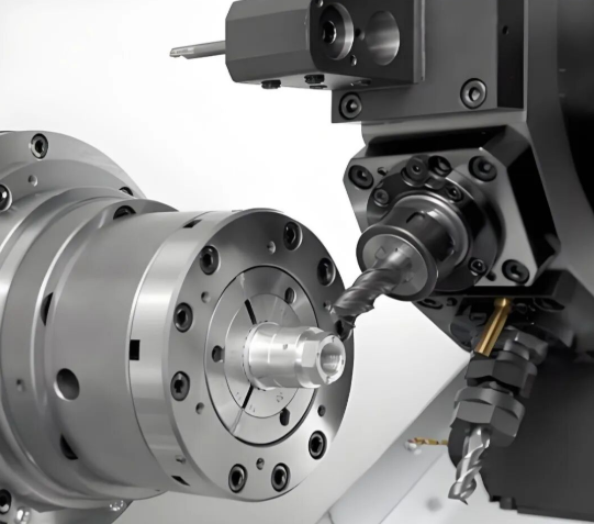
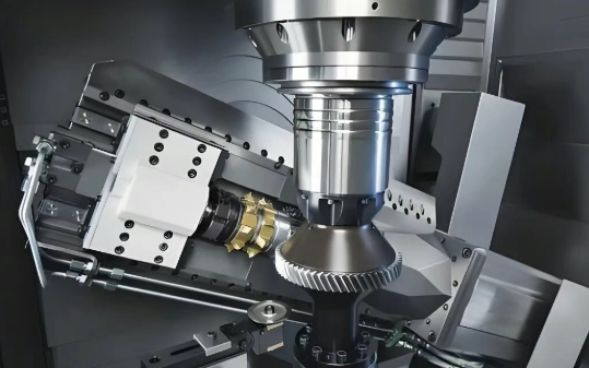
CNC frēzēšana un apstrāde uz pagrieziena mašīnas sarežģītām ģeometrijām
Kad jūsu detaļām nepieciešamas sarežģītas 3D funkcijas, dobumi vai daudzas ass apstrādes operācijas, CNC frēzmašīnas kļūst par jūsu galveno risinājumu. CNC vadības frēzmašīna noņem materiālu, izmantojot rotējošus griezējinstrumentus, kas pārvietojas pa vairākām asīm — parasti trīs līdz piecām. Tas padara to ideālu sarežģītu korpusu, skavu un komponentu ražošanai ar stingriem precizitātes prasībām.
Galvenās CNC frēzēšanas priekšrocības:
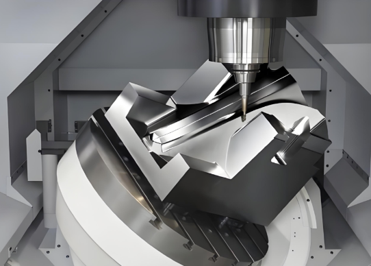
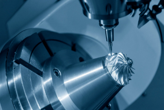
- Daudzassu darbības spēja: 3 ass, 4 ass un 5 ass konfigurācijas apstrādā arvien sarežģītākas ģeometrijas
- Materiālu daudzveidība: Efektīvi apstrādā alumīniju, tēraudu, titānu un eksotiskās sakausējumus
- Tiešās izmēru tolerances: Sasniedz ±0,001" līdz ±0,005", atkarībā no mašīnas kvalitātes un iestatījuma
- Virsmas apstrādes iespējas: Ražo virsmas apstrādi no rupjas materiāla noņemšanas līdz spoguļveidīgām virsmām
CNC latīšanas mašīna, pretēji, ir īpaši piemērota cilindriskiem detaļu veidojumiem. Apstrādājamais priekšmets rotē, kamēr griezējinstrumenti noņem materiālu — ideāli piemērota vārpstām, vārtiem, adatām un vītņotām sastāvdaļām. Ja jūsu detaļai ir rotācijas simetrija, tās apstrāde parasti ir lētāka un ātrāka nekā tās pašas ģeometrijas frēzēšana.
Lāzeru un plazmas griešana loksnes metālam
Loksnes metāla lietojumiem nepieciešams citāds pieejas veids. CNC griešanas mašīna, kas izmanto lāzera vai plazmas tehnoloģiju, ar izcilu ātrumu un efektivitāti griež plakanus kontūras veidojumus no loksnes materiāla.
Lāzera griešana koncentrē intensīvu gaismu, lai grieztu ar ķirurģisku precizitāti. Saskaņā ar industrijas testēšana , lāzera griešana ir līderpozīcijā tievo loksņu apstrādē, īpaši tad, ja nepieciešami smalki detāli vai precīzi caurumi. Koncentrētā staru kūle veido asus stūrus un gludas malas, kas bieži vien nepieprasa papildu apstrādi.
Lāzera griešana darbojas vislabāk, ja:
- Materiāla biezums paliek zem ½ collas
- Detaļām nepieciešami sarežģīti dizaini ar maziem elementiem
- Tīri malas bez sekundārās apstrādes ir būtiskas
- Lielapjoma ražošana prasa ātrumu un vienveidību
Plazmas griešanas izmanto elektrisko loku un saspiestu gāzi, lai izkausētu vadītspējīgos metālus. Ja jūs griežat tērauda plāksni ar biezumu ½" vai biezāku, plazmas griešana nodrošina vislabāko ātrumu un izmaksu efektivitāti. To izmanto metāla griešanas mašīnu metālapstrādes uzņēmumi strukturālā tēraudā, smago aprīkojumu daļās un kuģubūves komponentos.
Plazmas griešana dominē tad, kad:
- Strādājat ar bieziem vadītspējīgiem metāliem (tērauda plāksne 1" vai biezāka)
- Ātrums ir svarīgāks nekā precizitāte malās
- Budžeta ierobežojumi ierobežo tehnoloģiju izvēli — plazmas sistēmu cena ir aptuveni puse no salīdzināmām ūdensstrūkas iekārtām
Ūdensstraumes tehnoloģija siltumjutīgiem metāliem
Ko darīt, ja nevarat atļauties siltuma ietekmētās zonas? Metāla griešanas mašīna, kas izmanto ūdensstrūkas tehnoloģiju, eleganti risina šo problēmu. Augsspiediena ūdens, kas sajaukts ar abrazīvu, griež cauri gandrīz jebkuram materiālam — tēraudam, titānam, varam, pat kompozītiem — bez siltuma veidošanā.
Šis aukstā griešanas process kļūst būtisks:
- Aeronautikas komponentiem, kur metallurgiskā integritāte nedrīkst tikt kompromitēta
- Siltumjūtīgas sakausējums, kas deformētos termiskās slodzes ietekmē
- Biezas materiālu kārtas (dažos pielietojumos līdz 12"+)
- Dažādu materiālu kombinācijas, kurām nepieciešams viens griešanas risinājums
Ūdensstrūkas tirgus, pēc prognozēm, 2034. gadā sasniegs vairāk nekā 2,39 miljardus USD, atspoguļojot pieaugošo pieprasījumu pēc šīs bezsiltuma griešanas iespējas.
| Procesa tips | Labākie metāla pielietojumi | Tipiskās atļautās novirzes | Ātrums | Ideālas detaļu veidi |
|---|---|---|---|---|
| CNC frēzēšana | Alumīnijs, tērauds, titāns, vara sakausējums | ±0,001" līdz ±0,005" | Mērens | Sarežģīti 3D komponenti, korpusi, balstiekārtas, veidne |
| CNC virpošana | Visi apstrādājamie metāli | ±0,001" līdz ±0,005" | Ātrs cilindrisku detaļu griešanai | Vārpsti, adatas, vārpstu ieliktni, vītne veidotas sastāvdaļas |
| Lāzera griešana | Tievas tērauda, nerūsējošā tērauda un alumīnija loksnes | ±0,005" līdz ±0,010" | Ļoti ātrs uz plāniem materiāliem | Sarežģīti plakani profili, elektronikas korpusi |
| Plazmas griešanas | Biezs tērauds, alumīnijs, varš (vadītspējīgi materiāli) | ±0,020" līdz ±0,030" | Visātrākais bieziem metāliem | Konstrukcijas komponenti, smago aprīkojuma daļas |
| Ūdensstrūklas griešana | Jebkura metāla veids, tostarp siltumjūtīgas sakausējumi | ±0,005" līdz ±0,010" | Lēnāk nekā termālās metodes | Aerokosmiskas daļas, biezas materiālu plāksnes, precīzi profili |
Daudzas veiksmīgas izgatavošanas darbnīcas izmanto vairākas tehnoloģijas. CNC frēzmašīnas apstrādā sarežģītas mehāniski apstrādātas komponentes, kamēr lāzera vai plazmas sistēmas apstrādā loksnes metāla profilus. Galvenais ir pielāgot konkrēto materiāla veidu, detaļas ģeometriju un ražošanas apjomu tai tehnoloģijai, kas nodrošina optimālus rezultātus.
Kad jūsu CNC procesa iespējas ir skaidras, nākamais būtiskais lēmums ir šo tehnoloģiju pielāgošana konkrētiem metāliem — jo alumīnijs rīkojas ļoti atšķirīgi nekā titāns vienādos griešanas apstākļos.
Metālu pielāgošana piemērotajam CNC procesam
Jūs esat izvēlējušies savu CNC tehnoloģiju — bet tieši šeit daudzi projekti nonāk grūtībās. Tie paši frēzēšanas parametri, kas lieliski darbojas ar alumīniju, iznīcinās jūsu instrumentus, ja tos izmanto titāna apstrādei. Kāpēc? Jo katrs metāls ir ar savām unikālajām īpašībām, kas prasa specifiskas apstrādes pieejas.
Izpratne par to, kā cietība, apstrādājamības rādītāji un siltumvadītspēja ietekmē CNC procesu izvēli, atdala veiksmīgus projektus no dārgiem neveiksmīgiem rezultātiem. Apskatīsim precīzi, kuri CNC metāli vislabāk kombinējas ar kuriem procesiem.
Alumīnija un mīksto metālu apstrāde
Jautājiet jebkuram apstrādātājam par viņa vēlamāko materiālu, un alumīnijs bieži vien ieņem pirmo vietu. Šai preferenci ir labas iemesls. Alumīnija CNC mašīna var darboties ievērojami augstākās ātrumās nekā tērauda iestatījumi, jo alumīnija lieliskā apstrādājamība samazina griešanas spēkus un rada mazāk siltuma.
Pēc nozares speciālistu viedokļa, alumīnijs ir vēlamākais materiāls CNC apstrādei tāpēc, ka tam piemīt lieliska apstrādājamība, tas ir viegls, korozijai izturīgs un to var anodizēt, lai uzlabotu virsmas īpašības.
- Alumīnijs (6061, 7075): Ideāli CNC frezēšana un vēršana cNC mašīna alumīnijam apstrādā sarežģītas ģeometrijas augstā ātrumā. Ieteicams izmantot aerosaimniecības stiprinājumiem, automašīnu komponentiem un elektronisko ierīču korpusiem. Biezuma ierobežojumi ir minimāli — ūdensstrūkas griezējs var griezt alumīniju līdz 12 collu (30,48 cm) biezumam.
- Misīns: Izcilā apstrādājamība padara to ideālu precīzai pagriešanas apstrādei. CNC pagriezējmašīnas ražo precīzus savienojumus, vārstus un dekoratīvus komponentus. Materiāla zemās berzes īpašības ievērojami samazina rīku nodilumu.
Strādājot ar mīkstiem metāliem, galvenais jūsu uzmanības objekts pārslīd no griešanas grūtībām uz izmēru precizitātes uzturēšanu. Mīkstāki materiāli var novirzīties zem griešanas spiediena, tāpēc CNC alumīnija mašīnas iestatīšanai ir būtiski pareizi nostiprināt detaļu un izmantot piesardzīgas griešanas dziļuma stratēģijas.
Tērauda un nerūsējošā tērauda apstrādes apsvērumi
Pārejot no alumīnija uz CNC tēraudu, rodas citu veidu izaicinājumi. Tērauda augstāka cietība nozīmē lēnākus griešanas ātrumus, palielinātu rīku nodilumu un lielāku siltuma izdalīšanos. Tomēr šie kompromisi nodrošina detaļas ar augstāku izturību un ilgmūžību.
Tērauda CNC mašīnai ir nepieciešama izturīga konstrukcija un pietiekama stingrība, lai izturētu palielinātās griešanas spēles. Šeit ir svarīgākā informācija par bieži izmantotajām tērauda kvalitātēm:
- Mīkstais tērauds (1018, 1045): Labi apstrādājams ar vidēju cietību. CNC frēzēšana un pagriešana veicas labi, bet plazmas griešana ir īpaši efektīva biezām loksnes lietojumprogrammām. Ideāls strukturālo komponentu, stiprinājumu un vispārējam lietojumam paredzēto detaļu izgatavošanai.
- Nerūsējošais tērauds (304, 316): Piedāvā augstu izturību, lielisku korozijas izturību un labu karstumizturību — tādēļ tas ir ideāls aviācijas, medicīnas un jūras rūpniecības nozarēm. Tomēr apstrādes laikā notiekošā materiāla sacietēšana prasa asus instrumentus un vienmērīgu padosi, lai novērstu virsmas sacietēšanu.
- Rīku tērauds (D2, A2): Ārkārtīgi cietš pēc termoapstrādes. Ieteicams veikt CNC frēzēšanu pirms sacietēšanas, bet galīgās izmēru iegūšanai pēc termoapstrādes izmanto šlīfēšanas operācijas.
Loksnes metāla lietojumiem vai varat izmantot CNC frēzmašīnu tērauda apstrādei? Lai arī tas ir iespējams ar atbilstošiem rīkiem, lāzera vai plazmas griešana parasti nodrošina labākus rezultātus plakanām profilēm. CNC frēzmašīnas tērauda apstrāde labāk darbojas ar mīkstāku alumīnija loksni nekā ar cietinātu tēraudu.
Grūti apstrādāmi metāli, piemēram, titāns un varš
Daži metāli pārslodz CNC iespējas līdz to robežām. Titāns un varš katrs rada unikālus izaicinājumus, kuri prasa specializētus pieejas veidus.
Tītanis apvieno ārkārtīgi augstu stiprības attiecību pret svaru ar grūti panākamu apstrādājamību. Saskaņā ar apstrādes pētījumiem titāns rada izaicinājumus, tostarp augstu rīku nodilumu un zemu siltumvadītspēju. Šie faktori prasa specializētus rīkus, dzesēšanas tehniskas metodes un rūpīgu apstrādes parametru kontroli.
- Titāns (5. klase, 23. klase): Izmantot CNC frēzēšanu ar karbīda vai keramikas rīkiem. Ūdens dzesēšanas šķidruma lietošana ir obligāta — titāna zemā siltumvadītspēja liek siltumam koncentrēties griešanas malā. Ūdensstrūkas griešana pilnībā novērš siltuma ietekmēto zonu kritiskiem aviācijas komponentiem.
- Varš: Izcilās siltumvadītspējas un elektriskās vadītspējas dēļ varš ir būtisks siltummainiem un elektriskajiem komponentiem. Tomēr tā mīkstums rada lipīgus skapušus, kas var pielīpt griešanas rīkiem. Asu rīku izmantošana un piemērotas skapušu noņemšanas stratēģijas ir būtiskas.
- Bronza: Bronza ir vieglāk apstrādājama nekā tīrs varš un labi darbojas CNC pagriežamās apstrādēs bumbierveida lodziņiem, uzvalciņiem un jūras aprīkojumam. Tās dabiskās smērības īpašības samazina berzi griešanas laikā.
Metāla CNC lietojumi grūti apstrādājamām materiālu grupām iegūst priekšrocības no modernām rīku ceļa stratēģijām. Augsts ātrums ar vieglu radiālo iedarbību ļauj kontrolēt siltumu, saglabājot produktivitāti grūtajos sakausējumos.
Materiāla biezums arī ietekmē procesa izvēli. Laseru griešanai parasti tiek apstrādāts tērauds līdz ½ collai, kamēr plazmas griešana efektīvi sagriež līdz 1"+ biezus plāksnes. Ūdensstrūkas griešana apstrādā visbiezākos materiālus — dažos pielietojumos līdz pat 12" — bez siltuma izkropļojumu riska.
Šo materiālu un apstrādes procesu attiecību izpratne sagatavo jūs nākamajam kritiskajam lēmumam: detaļu projektēšanai tā, lai tās faktiski būtu ražojamas. Pat ideālais metāla un apstrādes procesa savienojums neizdosies, ja jūsu dizains pārkāpj pamata mašīntehniskās ierobežojumu prasības.
Dizaina principi, kas padara CNC metāla detaļas ražojamas
Jūs esat izvēlējies piemērotu CNC procesu un to pielāgojis izvēlētajam metālam. Tagad pienāk lēmuma brīdis, kas sagādā grūtības pat pieredzējušiem inženieriem: detaļu projektēšana tā, lai tās faktiski varētu efektīvi ražot. Pat šķietami nenozīmīgs dizaina lēmums — piemēram, lieku asu stūri vai pārmērīgi stingru precizitātes prasību norādīšana — var pārvērst vienkāršu CNC frēzēšanas operāciju sarežģītā, laikietilpīgā un grūti realizējamā procesā.
Pēc ražošanas pētījumi efektīva ražošanai piemērotas konstruēšanas īstenošana var samazināt ražošanas izmaksas par 15–40 % un saīsināt piegādes laikus par 25–60 % salīdzinājumā ar neoptimalizētām konstrukcijām. Tas ir starpība starp termiņa ievērošanu un projektā iestājušos vairāku nedēļu kavējumu.
Jūsu CAD failu sagatavošana CNC veiksmīgai apstrādei
Pirms jūsu konstrukcija nonāk CNC frezēšanas mašīnā, tai jāspēj skaidri komunicēt ar programmēšanas programmatūru. Jūsu izvēlētais faila formāts un tā sagatavošanas veids tieši ietekmē to, vai jūsu detaļas pirmajā reizē tiks izgatavotas pareizi.
Visplašāk izmantotie failu formāti CNC metāla apstrādei ir:
- STEP (.step/.stp): Nozaru standarts 3D modeļiem. STEP faili saglabā līkņu un virsmu matemātiskās definīcijas, tādēļ tie ir ideāli piemēroti CNC frezēšanas mašīnu programmēšanai.
- IGES (.iges/.igs): Vēl viens universāls 3D formāts, kas uzticami pārnes ģeometriju starp dažādām CAD sistēmām.
- DXF/DWG: Būtisks 2D profilēšanai un griešanas operācijām lāzer-, plazmas vai ūdensstrūkas sistēmās.
- Iebūvētie CAD formāti: SolidWorks, Fusion 360 vai citi platformai specifiski faili darbojas, ja jūsu ražotājs izmanto savietojamu programmatūru.
Šeit ir būtisks padoms, ko daudzi inženieri izlaiž: vienmēr pievienojiet savam 3D CAD failam 2D tehnisko zīmējumu PDF formātā. Šajā zīmējumā jānorāda kritiskās novirzes, virsmas apstrādes prasības un jebkādas montāžas piezīmes. Kā norāda ražošanas speciālisti, tas palīdz novērst nezināšanu un nodrošina, ka jūsu dizaina nolūki precīzi tiek pārnesti uz ražošanas telpu.
Pirms iesniegšanas pārbaudiet šos būtiskos datus:
- Mērvienības ir skaidri definētas (collas vai milimetri)
- Modeļa izcelsme ir pareizi iestatīta fiksācijai
- Visa ģeometrija ir noslēgta un ūdensnecaurlaidīga — bez spraugām vai pārklājošām virsmām
- Teksts un logotipi ir pārveidoti par ģeometriju, nevis palikuši kā aktīvi fonti
Kritiskie konstrukcijas elementi, kas ietekmē apstrādājamību
Pat ideāli CAD faili neizdodas, ja to pamatā esošā ģeometrija pārkāpj pamatās mašīnāšanas ierobežojumus. Maza CNC mašīna vai liela 3 ass CNC mašīna — metāla griešanas fizikālie principi paliek tie paši. Šie ir svarīgākie elementi:
Sieniņu minimālais biezums: Tievas sienas rada vibrācijas griešanas laikā, kas izraisa trīcēšanas pēdas un izmēru neprecizitāti. Saskaņā ar DFM norādījumiem minimālā sienu biezuma vērtība ir atkarīga no materiāla — alumīnija detaļām jāsaglabā vismaz 0,8 mm biezas sienas, tērauda detaļām nepieciešams vismaz 1,0 mm biezas sienas, bet nerūsējošā tērauda detaļām nepieciešamas vismaz 1,2 mm vai biezākas sienas.
Iekšējo stūru rādiusi: Šeit daudzas dizaina risinājumi kļūst nepareizi. Galvgrieži ir apaļi — tie fiziski nevar izveidot asus 90 grādu iekšējos stūrus. Norādiet minimālo radiusu 0,030" (0,76 mm) standarta instrumentu savietojamībai. Dziļiem dobumiem šo radiusu palieliniet līdz 0,060" (1,52 mm) vai vairāk, lai samazinātu instrumenta noliekšanos.
Caurumu dziļuma attiecības: Standarta urbji darbojas efektīvi līdz pat četrkāršai to diametra dziļumam. Tālāk nepieciešami specializēti instrumenti, kas palielina izmaksas un ražošanas laiku. 6 mm caurumam ideālais dziļums ir mazāks par 24 mm. Dziļākiem caurumiem apsveriet pakāpju veida diametrus vai citus apstrādes risinājumus.
Iekšējo atpakaļgriezumu ierobežojumi: Funkcijas, kas paslēptas zem izvirzītās ģeometrijas, prasa speciālus rīkus vai vairākas uzstādīšanas operācijas. Ja iespējams, projektējiet funkcijas, kas ir pieejamas no standarta rīku pieejas leņķiem — ģeometrijas orientācija pa X, Y un Z asīm samazina nepieciešamību pēc dārgām 5 ass apstrādes operācijām.
Kā izvairīties no parastajiem dizaina kļūdām
Dārgākās projektēšanas kļūdas nav acīmredzamas, līdz sākas ražošana. Izmantojiet šo pārbaudes sarakstu, lai problēmas identificētu pirms tās jums izmaksā laiku un naudu:
- Pievienojiet iekšējos stūru radiusus visām kabatām: Norādiet vismaz 1/3 no dobuma dziļuma kā stūra radiusu. Standarta rīku radiusu (3 mm, 6 mm) izmantošana samazina izmaksas, jo to dēļ mašīnists var izmantot parastus, stingrus rīkus.
- Novērsiet nazveida malas: Tur, kur divas virsmas krustojas asos leņķos, pievienojiet ārējus filletus 0,005–0,015 collu lielumā. Šīs malas tiek apstrādātas tīri un iztur apstrādi un manipulāciju, nesabojājoties.
- Saglabājiet pietiekamu sienas pret ribu attiecību: Ja izmantojat ribas stingrībai, turiet ribu biezumu 50–60 % no blakus esošās sienas biezuma, lai novērstu iedobumus un sprieguma koncentrācijas.
- Pārliecinieties, ka urbšanas dziļums atbilst vītņu griešanai: Uzurbēšanas dziļumiem jāpārsniedz uzurbēšanas dziļumi par urbjmašīnas ievadgaruma garumu — parasti 2–3 vītnes grieztajām urbjmašīnām.
- Turiet uzurbētās caurumus tālu no sienām: Vītņotās funkcijas novietojiet ar pietiekamu brīvumu no blakusesošajām virsmām, lai novērstu caururbšanu.
- Norādiet tikai nepieciešamās novirzes: Šauras pieļaujamās novirzes (±0,001 collas) izmaksas dramatiski palielina. Nekritiskām dimensijām izmantojiet standarta pieļaujamās novirzes (±0,005 collas).
- Sakārtojiet funkcijas ar galvenajām asīm: Detaļām, kurām nepieciešama 5 ass apstrāde, izmaksas ir par 300–600 % augstākas nekā 3 ass apstrādei. Dizainējiet funkcijas tā, lai tās būtu pieejamas no standarta orientācijām, kad to ļauj funkcionalitāte.
- Ņemiet vērā fiksēšanas prasības: Iekļaujiet pietiekamus piespieguma virsmas. CNC ierīcei jātur jūsu detaļa droši — plānas, elastīgas daļas bez atbilstošas atbalsta konstrukcijas deformēsies apstrādes laikā.
Atcerieties, ka katram pieļaujamajam noviržu apzīmējumam jābūt funkcionalitātes mērķim. Saskaņā ar ražošanas datiem, norādot ±0,002" pieļaujamās novirzes vietā par standarta ±0,005" pieaug piegādes laiks par 25–50 % un izmaksas attiecīgi palielinās. Uzdoties sev jautājumu: vai šai funkcijai patiešām nepieciešama šāda precizitāte, lai tā pareizi darbotos?
Kad jūsu dizains ir optimizēts ražošanai, nākamais solis ir pilnīgi saprast, ko tieši nozīmē jūsu lietojumprogrammai piemērotās pieļaujamās novirzes un virsmas apstrādes specifikācijas — un kā tās ietekmē gan kvalitāti, gan izmaksas.
Tolerances un virsmas apstrādes kvalitāte, kas nosaka detaļu kvalitāti
Šeit ir viena ražošanas realitāte, kas pārsteidz daudzus inženierus: tieši jūsu norādītās ±0,001" pieļaujamās novirzes varētu divkāršot jūsu detaļas izmaksas un trīskāršot piegādes laiku. Saskaņā ar ražošanas pētījumiem attiecība starp pieļaujamajām novirzēm un ražošanas sarežģītību nav lineāra — tā ir eksponenciāla.
Izpratne par to, kad precizitāte patiešām ir būtiska un kad tā ir inženierijas pārspīlējums, var pārvērst jūsu pieeju metāla apstrādei. Galvenais ir izvēlēties piemērotas precizitātes klases atbilstoši faktiskajai detaļas funkcijai, nevis pēc noklusējuma izvēlēties stingrākās specifikācijas, kuras jūsu CNC griezējs teorētiski spēj sasniegt.
Precizitātes klases metāla detaļām
CNC apstrādes precizitātes nosaka, cik daudz detaļa var novirzīties no savām ideālajām mērījumu vērtībām, tomēr joprojām pareizi darbojoties. Saskaņā ar precizitātes apstrādes speciālistiem, precizitātes ir būtiskas, jo neviena ražošanas metode nevar ražot detaļas ar absolūtu perfekcionismu — tās nodrošina, ka detaļas pareizi savienojas, darbojas paredzētajā veidā un atbilst kvalitātes standartiem.
Iedomājieties, ka precizitātes iedalās trīs praktiskās kategorijās:
Stingrās precizitātes (±0,001″ līdz ±0,005″): Saglabājiet šos izmērus kritiskajām saskarnēm, kur precizitāte tieši ietekmē funkciju. Bultskrūvju savienojumi, vārpstas balsta virsmas un blīvēšanas virsmas bieži prasa šādu kontroles līmeni. CNC metāla frēzēšanas mašīna var sasniegt šādus noviržu lielumus, taču process prasa temperatūras kontrolētu vidi, mašīnu rīku termisko stabilizāciju un specializētus pārbaudes procesus.
Standarta novirzes (±0,005″ līdz ±0,015″): Šis diapazons aptver lielāko daļu vispārējo apstrādes pielietojumu. Montāžas kronšteinu caurumi, piestiprināšanas virsmas un brīvās vietas parasti ideāli darbojas ar šādām specifikācijām. Standarta noviržu lielumi ļauj efektīvi ražot bez liekas kvalitātes kontroles sloga.
Brīvās novirzes (±0,015″ līdz ±0,030″+): Piemērotas rupjai apstrādei, nekritiskām funkcijām un virsmām, kurām paredzētas papildu apstrādes operācijas. Tur, kur funkcija to atļauj, brīvāku noviržu lielumu norādīšana var ievērojami samazināt CNC apstrādes izmaksas, nekaitot detaļas ekspluatācijas raksturlielumiem.
ISO 2768 standarts nodrošina noderīgu rāmi, sadalot pieļaujamās novirzes četrās klasēs: Precīza (f) — augstas precizitātes detaļām, Vidēja (m) — vispārējām lietojumprogrammām, Rupja (c) — mazāk kritiskām komponentēm un Ļoti rupja (v) — rupjam apstrādes procesam.
Virsmas apdarēšanas standarti un Ra vērtības
Virsmas raupjums mēra nelielos pacēlumus un depresijas, kas palikuši uz jūsu detaļas pēc apstrādes — mikroskopisko virsmas struktūru, kas ietekmē berzi, nodilumu, blīvēšanu un izskatu. Pēc virsmas apstrādes speciālistu teiktā, pat pēc tādiem procesiem kā smilšstrādāšana, polīrēšana vai citi pielietotie virsmas apstrādes veidi daļējs raupjums var palikt kā neizbēgams rezultāts no metālapstrādes mašīnu griezējdarbībām.
Ra (Vidējā raupjuma vērtība) ir visbiežāk lietotais mērījums — tas vidējo virsmas pacēlumu un depresiju augstumu atšķirības. Šeit ir praktiskā nozīme dažādām Ra vērtībām:
- Ra 6,3 µm (250 µin): Standarta apstrādātā virsma. Piemērota skavām, vākiem un nekritiskām virsmām. Sasniedzama ar pamata frēzēšanas operācijām.
- Ra 3,2 µm (125 µin): Labs labotā virsmas apstrāde, kas prasa kontrolētus griešanas parametrus. Bieži izmanto redzamām detaļām un vispārīgām mehāniskām savienojuma vietām.
- Ra 1,6 µm (63 µin): Ļoti gluda virsma, kas prasa asus rīkus un optimizētus ātrumus. Izmanto bultiņu virsmām, blīvējuma virsmām un precīziem savienojumiem.
- Ra 0,8 µm (32 µin): Ārkārtīgi gluda virsma, kas bieži prasa papildu apstrādes operācijas, piemēram, slīpēšanu. Kritiska hidrauliskajām sastāvdaļām un augstas precizitātes montāžām.
- Ra 0,4 µm (16 µin) un gludāka: Spoguļveidīgas virsmas, kas prasa līmēšanu, polēšanu vai specializētas procesus. Atrezervēta optiskajām sastāvdaļām un ārkārtīgi precīzām lietojumprogrammām.
Dažādi CNC procesi dabiski nodrošina dažādu virsmas kvalitāti. Mazs CNC frēzēšanas stends ar pareiliem parametriem rada Ra 1,6–3,2 µm, kamēr pagriešanas operācijas parasti sasniedz Ra 0,8–1,6 µm cilindriskās virsmās. Slīpēšana ļauj sasniegt Ra 0,4 µm un gludāku.
Kad precizitāte ir visvairāk svarīga
Dārgākā pieļaujamā novirze bieži vien ir tā, kas nepiedāvā nekādu funkcionālu priekšrocību. Saskaņā ar ražošanas izmaksu analīzi, pāreja no rupjas apstrādes pieļaujamajām novirzēm (±0,030 collas) uz precīzām pieļaujamajām novirzēm (±0,001 collas) izmaksas palielina aptuveni 4 reizes, kamēr ultra-precīzās pieļaujamās novirzes (±0,0001 collas) var izmaksāt 24 reizes vairāk nekā standarta apstrāde.
Griešanas ātrumi un padziņas ātrumi tieši ietekmē gan pieļaujamās novirzes, gan virsmas apdarei rezultātus. Ātrākas padziņas uzlabo ražību, bet var pasliktināt virsmas kvalitāti. Lēnāki ātrumi ar vieglākiem griezumiem nodrošina smalkāku virsmas apdari, tačau pagarinās cikla ilgumu. Jūsu apstrādātājs šos parametrus pielāgo atbilstoši jūsu specifikācijām — tāpēc norādiet tikai to, kas jums patiešām nepieciešams.
| Tolerances klase | Tipisks diapazons | Tipiskās Ra vērtības | Lietojuma jomas | Relatīvais izmaksu ietekmes līmenis |
|---|---|---|---|---|
| Ultraponnā precizitāte | ±0,0001" līdz ±0,0005" | Ra 0,2–0,4 µm | Optiskās sastāvdaļas, aviācijas un kosmonautikas gultņi, medicīniskās implanti | 20–24 reizes pamatvērtība |
| Cieša/precīza | ±0,001" līdz ±0,005" | Ra 0,8–1,6 µm | Gultņu presēšana, vārpstu balsta virsmas, blīvēšanas virsmas, precīzas montāžas | 3–4 reizes pamatvērtība |
| Standarta | ±0,005 collas līdz ±0,015 collas | Ra 1,6–3,2 µm | Vispārīgi mehāniskie komponenti, stiprinājumi, korpusi, lielākā daļa ražošanas komponentu | 1× pamatlīmenis |
| Brīvs/vaļīgs | ±0,015" līdz ±0,030" | Ra 3,2–6,3 µm | Nekritiskas īpašības, rupja apstrāde, virsmas, kurām paredzētas papildu apstrādes operācijas | 0,7–0,8× pamatlīmenis |
Pirms norādāt stingrus izmēru noviržu noteikumus, uzdoties sev jautājumus: Vai šis izmērs tieši ietekmē montāžas pieguldi? Vai šeit notiekošās novirzes izraisīs funkcionālu atteici? Ja atbilde ir nē, standarta izmēru noviržu noteikumi, visticamāk, atbilst jūsu vajadzībām un vienlaikus ļauj saglabāt pieņemamas ražošanas izmaksas.
Kad izmēru noviržu un virsmas apstrādes prasības ir noteiktas, nākamais būtiskais lēmums ir pārliecināties, ka jūsu gatavie komponenti patiešām atbilst šīm specifikācijām — kvalitātes kontroles uzdevums, ko daudzi ražotāji risina nevienmērīgi.
Kvalitātes kontroles metodes CNC metāla komponentiem
Jūs esat norādījuši stingrus pieļaujamās novirzes robežas un precīzus virsmas apstrādes parametrus—bet kā jūs faktiski pārbaudāt, vai jūsu detaļas atbilst šiem prasījumiem? Tieši šeit daudzas metāla izgatavošanas projektu problēmas kļūst acīmredzamas. Bez rūpīgas kvalitātes kontroles jūsu norādītās ±0,001 collu pieļaujamās novirzes pastāv tikai uz papīra.
Pēc kvalitātes kontroles speciālisti cNC apstrādes kvalitātes kontroles galvenais mērķis ir minimizēt kļūdas, precīzi identificējot un novēršot potenciālas problēmas. Bez pienācīgas pārbaudes defektīvas detaļas var izraisīt ievērojamus finansiālus zaudējumus un negatīvu reputāciju nozarē.
Pārbaudes metodes, kas apstiprina detaļu kvalitāti
Mūsdienu CNC apstrādes aprīkojums ražo detaļas ar izcilu precizitāti—taču precizitāte neko nenozīmē bez verifikācijas. Šeit ir aprakstīts, kā ražotāji apstiprina, ka jūsu metāla CNC apstrādes rezultāti patiešām atbilst norādītajām specifikācijām.
Koordinātu mērīšanas mašīnas (CMM): Šīs sarežģītās sistēmas izmanto taktilos zondes vai lāzera sensorus, lai iegūtu precīzus izmēru datus no sarežģītām ģeometrijām. Koordinātu mērīšanas mašīna (CMM) pārvietojas pa X, Y un Z asīm, pieskaroties vai skenējot jūsu detaļu programmētajos punktos, pēc tam salīdzinot mērījumus ar jūsu CAD modeli. CNC aprīkojumam, kas ražo augstas precizitātes aerokosmosa vai medicīniskās detaļas, CMM pārbaude bieži vien ir obligāta.
CMM iespējas ietver:
- Mērījumu precizitāte līdz 0,02 mm (20 mikroniem) uz modernām sistēmām
- Razolūcija 0,01 mm, lai fiksētu smalkas ģeometriskās detaļas
- Automatizētas pārbaudes procedūras, kas nodrošina atkārtojamību visā ražošanas ciklā
- 3D metroloģijas ziņojumi, kuros dokumentēts katrs kritiskais izmērs
Virsmas raupjuma pārbaude: Vai atceraties Ra vērtības no jūsu specifikācijām? Profilometri noskano jūsu detaļas virsmu, mērot mikroskopiskās virsotnes un iedobes, kas nosaka virsmas kvalitāti. Šī verifikācija nodrošina, ka jūsu CNC apstrādē metāla operācijas ir sasniegušas prasīto virsmas apstrādes kvalitāti — vai nu Ra 0,8 µm blīvējuma virsmām, vai arī Ra 3,2 µm vispārējām lietojumprogrammām.
Nenodarbojošās pārbaudes (NDT): Daži defekti slēpjas zem virsmas. Ultraskaņas izmēģinājumi nosūta skaņas viļņus caur jūsu metāla daļām, atklājot iekšējus tukšumus, iekļaušanas vai plaisas, kas nav redzamas ar aci. Magnētisko daļiņu pārbaude atklāj virsmas un tuvu virsmai esošas nepilnības feromagnētiskos materiālos. Šīs metodes verificē strukturālo integritāti, nebojājot komponentu.
Galvenie kvalitātes kontroles punkti metāla CNC apstrādē ir:
- Pirmā izstrādājuma pārbaude: Pilnīga sākotnējo detaļu izmēru noteikšana pirms pilnas ražošanas uzsākšanas
- Procesa monitorings: Regulāras izmēru pārbaudes ražošanas laikā, lai agrīnā stadijā konstatētu novirzes
- Beigās pārbaude: Pilnīga verifikācija pret visām rasējumu specifikācijām pirms nosūtīšanas
- Statistikas procesa kontrole: Nepārtraukta datu vākšana, kas laika gaitā seko ražošanas vienveidībai
- Rīku nodiluma uzraudzība: Regulāras pārbaudes, kas novērš izmēru novirzes, ko izraisa griešanas rīku degradācija
Nozares sertifikācijas, kas garantē standartus
Kā jūs varat zināt, ka rūpnieciskā CNC mašīnu darbnīca patiešām ievēro stingrus kvalitātes procedūru prasības? Nozaru sertifikāti nodrošina neatkarīgu trešās puses verifikāciju, ka kvalitātes sistēmas atbilst stingrām prasībām.
IATF 16949 automašīnu rūpniecībai: Pēc sertifikācijas ekspertiem iATF 16949 standarts pievieno daudz prasību procesu projektēšanai un kontrolei, konkrētu personu kompetencei, statistiskajām metodēm un mērīšanas sistēmu analīzei. Šis automobiļu nozares specifiskais standarts arī obligāti paredz kontroli pār ārējiem piegādātājiem, ražošanas grafiku un kopējo produktīvo apkopi. Šasijām, suspensijām un strukturālajām sastāvdaļām IATF 16949 sertifikācija norāda ražotāja apņemšanos nodrošināt automobiļu nozares kvalitāti.
AS9100 aviācijas nozarē: Aizsardzības un kosmosa rūpniecība prasa vēl stingrākas kontroles. AS9100 standarts koncentrējas uz produkta drošību, konfigurācijas pārvaldību un viltošanas novēršanu. Metālapstrādes mašīnām, kas ražo lidojumam kritiskas sastāvdaļas, jādarbojas šo standartu ietvaros, turklāt tiek izvirzītas papildu prasības laikā notiekošai piegādei un cilvēkfaktoru pārvaldībai.
Abi sertifikāti balstās uz ISO 9001:2015 pamatprincipiem, pievienojot nozares specifiskas prasības, kas risina unikālos kvalitātes izaicinājumus.
Dokumentācijas un izsekojamības prasības
Kvalitātes kontrole ir plašāka par fizisko pārbaudi — pareiza dokumentācija veido dokumentu ceļu, kas pierāda atbilstību. Saskaņā ar materiālu sertifikācijas speciālistiem šie dokumenti pierāda materiāla sastāvu, īpašības un atbilstību nozaru standartiem. Bez tiem kvalitātes verifikācija vai izsekojamības nodrošināšana kļūst neiespējama.
Materiāla testa ziņojumi (MTR): To sauc arī par rūpnīcas testa ziņojumiem; šie dokumenti apstiprina jūsu izejmateriāla ķīmisko sastāvu un mehāniskās īpašības. Kritiskām lietojumprogrammām MTRs ļauj izsekot jūsu detaļai līdz konkrētajam metāla kausējuma numuram, no kura tā izgatavota.
Atbilstības sertifikāti (CoC): Šie vispārējie dokumenti apliecina, ka pabeigtās detaļas atbilst visām norādītajām prasībām — tostarp izmēriem, novirzēm, virsmas apstrādei un materiāla īpašībām.
Pirmā izstrādājuma pārbaudes ziņojumi (FAIR): Detalizēta dokumentācija par katru izmēru, ko mēra sākotnējo ražošanas detaļu, bieži vien nepieciešama pirms automobiļu vai aeronautikas klienti apstiprina pilnu ražošanu.
Iedomajieties, ka kritiska sastāvdaļa nolūst ekspluatācijā. Ar uzticamu izsekojamību var izsekot katru soli — no izejvielu avota līdz apstrādes parametriem un beigām līdz gala pārbaudes rezultātiem. Šāda dokumentācija nodrošina neaizstājamus datus saknes cēloņu analīzei un nepārtrauktai uzlabošanai.
Šo kvalitātes kontroles metodžu izpratne palīdz efektīvi novērtēt ražošanas partnerus — taču kā noteikt, vai šīs spējas vajadzētu attīstīt iekšēji vai sadarboties ar specializētiem izgatavotājiem? Šis lēmums būtiski ietekmē gan jūsu izmaksas, gan jūsu kontroli pār kvalitātes rezultātiem.
Spēju izveidošana pretī sadarbībai ar CNC speciālistiem
Šis ir 250 000 USD jautājums, ar kuru katrs inženieru kolēktīvs galu galā saskaras: vai jāinvestē savā CNC aprīkojumā vai jāsadarojas ar specializētiem izgatavotājiem? Saskaņā ar ražošanas izmaksu analīzi, lielākā daļa komandu šī lēmuma patiesās izmaksas novērtē nepareizi par 60 % vai vairāk — bieži atklājot slēptās izmaksas tikai pēc tam, kad jau ir ieguldīts ievērojams kapitāls.
Atbilde ir atkarīga no jūsu ražošanas apjoma, kvalitātes prasībām un no tā, kā jūs vērtējat kapitāla elastību salīdzinājumā ar operacionālo kontroli. Apskatīsim, ko katrs ceļš patiesībā izmaksā.
Iekšējās CNC iekārtu iegādes apsvērumi
Novērtējot pārdošanai piedāvātu CNC mašīnu, cena uz etiķetes atklāj tikai daļu no stāstījuma. Cik daudz patiesībā izmaksā CNC mašīnas iegāde un ekspluatācija? Saskaņā ar kopējās īpašumtiesību izmaksu pētījumu , aprīkojuma izmaksas parasti veido tikai 40 % no jūsu kopējās investīcijas — operatoru algas, telpu prasības un rīku komplekts veido pārējos 60 %.
Šeit ir reālistisks pirmā gada investīciju apjoms:
Ieejas līmeņa 3 ass iestatījums:
- Aprīkojums (CNC mašīnas cena): 50 000–120 000 USD
- CAM programmatūra (gadā): 5000–15 000 USD
- Sākotnējie rīki: 10 000–20 000 USD
- Operatora alga: 60 000–75 000 USD
- Apmācība un iekšējās darbības uzraudzība: 5000–10 000 USD
- Telpu prasības (gaisa kondicionēšana, platība): 24 000–36 000 USD
- Uzturēšana un remonts: 5000–10 000 USD
- Pirmā gada kopējā summa: 159 000–286 000 USD
Profesionāla 5 ass iestatīšana:
- Iekārtas (CNC mašīnas cena): 300 000–800 000 USD
- Uzlabota CAM programmatūra: 15 000–25 000 USD
- Sākotnējā rīku izgatavošana: 20 000–30 000 USD
- Pieredzes bagāts operators: 75 000–90 000 USD
- Apmācība un sertifikācija: 10 000–20 000 USD
- Telpu prasības: 36 000–60 000 USD
- Uzturēšana (8–12 % no aprīkojuma vērtības): 24 000–96 000 USD
- Pirmā gada kopējās izmaksas: 480 000–1 120 000 USD
Vai meklējat CNC frezni pārdošanai vai lētu CNC mašīnu? Būt uzmanīgam. Lēta CNC mašīna varētu ietaupīt sākotnējās izmaksas, taču bieži vien tai trūkst stingrības un precizitātes, kas nepieciešama regulārai metāla apstrādei. Tikai apguves process — parasti 12–18 mēneši — rada 40–60 % augstākas materiālu zudumu un 2–3 reizes garākas cikla laikus salīdzinājumā ar pieredzējušiem operatoriem.
Kad metāla izstrādājumu apstrādes pasūtīšana ārpus uzņēmuma ir lietderīga
Cik daudz vērtības ir CNC mašīnai, ja tā stāv neizmantota 80 % laika? Ikgadējam apjomam zem 300 detaļu nozares analīze rāda, ka pasūtot metāla izstrādājumu apstrādi ārpus uzņēmuma, ņemot vērā visas slēptās izmaksas, kopējās izmaksas parasti ir par 40–60 % zemākas.
Pasūtot metāla izstrādājumu apstrādi ārpus uzņēmuma, izmaksas atkarīgas no detaļas sarežģītības:
- Vienkāršas detaļas: 200–800 USD par detaļu (1–5 gabali), pie 25+ detaļām – 50 % atlaidne
- Vidējas sarežģītības detaļas: 800–2500 USD par detaļu, lielākiem apjomiem – 45 % atlaidne
- Augsta sarežģītība (5 ass darbs): 2500–10 000 USD par daļu, ar 40 % atlaidi lielākos apjomos
Papildus cenu noteikšanai par katru daļu, ārējās piegādes izmantošana nodrošina priekšrocības, kas vienkāršos izmaksu salīdzinājumos nav redzamas:
- Laiks līdz pirmajam izstrādājumam: Profesionālas darbnīcas piegādā produkts 1–3 dienās, savukārt iekšējai uzstādīšanai nepieciešamas nedēļas vai pat mēneši
- Nulle kapitāla risks: Nav nolietojuma, nav uzturēšanas problēmu, nav bažu par operatoru maiņu
- Uzreiz pieejama ekspertīze: Pieeja desmitiem gadu ilgai ražošanas pieredzei, neveidojot to iekšēji
- DFM atbalsts: Pieredzes bagātie izgatavotāji atklāj konstruktīvās problēmas, pirms tās kļūst dārgas
- Mēroga maināmība: No 1 prototipa līdz 1000 ražošanas daļām bez infrastruktūras izmaiņām
Kopējās īpašniecības izmaksu novērtēšana
Bezpeļņas punkts, kur iekšējās investīcijas sāk būt finansiāli izdevīgas, atrodas aptuveni 500–800 vidējas sarežģītības detaļu gadā, ko uztur 3–4 gadus. Zem šī sliekšņa ārējā pasūtījuma izmantošana gandrīz vienmēr ir izdevīgāka kopējās izmaksas ziņā.
| Faktors | Iekšējā CNC apstrāde | Āroutsorcinga pakalpojumi |
|---|---|---|
| Sākotnējā investīcija | 150 000–450 000+ USD pirmajā gadā | nav nepieciešams kapitāls |
| Izstrādājuma vienības cena (mazs apjoms) | Augsts — fiksētās izmaksas sadalītas pa nelielu detaļu skaitu | 200–2500 USD atkarībā no sarežģītības |
| Izstrādājuma vienības cena (liels apjoms) | Zemāks — amortizācijas priekšrocības kļūst redzamas | pieejami 40–50 % apjomu atlaidi |
| Ražošanas laika kontrole | Pilnīga kontrole pēc darbības uzsākšanas | standarta termiņš — 1–3 dienas; iespējams arī tās pašas dienas izpildes variants |
| Kvalitātes kontrole | Tieša uzraudzība, bet nepieciešama ekspertīze | Sertificētās darbnīcas nodrošina dokumentētus kvalitātes sistēmu |
| Uzplaukuma laiks | 12–18 mēneši līdz pilnīgai efektivitātei | Neuzvilkta pieeja pierādītajām spējām |
| Riska profils | Kapitāls saistīts; tehnoloģiju novecošana | Operacionālie izdevumi; elastība saglabāta |
Daudzas veiksmīgas komandas izmanto hibrīda pieeju: prototipus un sarežģītus komponentus, kuriem nepieciešama specializēta ekspertīze, ārēji pasūta, bet augstas apjoma vienkāršu ražošanu pārnes iekšēji, kad apjomi attaisno investīciju. Šī stratēģija saglabā kapitālu produktu izstrādes laikā, vienlaikus optimizējot izmaksu efektivitāti masveida ražošanā.
Apsveriet iespēju sākt ar ārējo pasūtīšanu, lai pārbaudītu produkta un tirgus atbilstību. Pārnesiet augstas apjoma komponentus iekšējā ražošanā tikai tad, kad esat pierādījuši stabili pieprasījumu un patiešām varat attaisnot pilnas īpašumtiesību izmaksas. Kapitāls, ko saglabājat, atlikdami aprīkojuma iegādi, var finansēt papildu inženierzinātniskās izstrādes vai tirgus izplešanos.
Vai nu jūs veidojat iekšējās spējas, vai arī sadarbojaties ar speciālistiem — viena problēma paliek nemainīga: kļūdu novēršana CNC metāla apstrādē, kas neizbēgami rodas. Kopīgo problēmu un to risinājumu izpratne palīdz jums nodrošināt kvalitāti neatkarīgi no jūsu ražošanas stratēģijas.
Kopīgo CNC metāla apstrādes problēmu novēršana
Pat vismodernākā CNC metāla mašīna saskaras ar problēmām. Kas atšķir uzņēmumus, kas nodrošina vienmērīgu kvalitāti, no tiem, kas cieš? Tas ir sapratne par to, kas izraisa problēmas pirms tām sabojāt jūsu detaļas. Pēc nozares pētījumiem ražošanas uzņēmumi katru gadu zaudē 5–20 % no savas ražošanas jaudas neparedzētai darbības pārtraukšanai — liela daļa šīs zaudējumu ir novēršama, ja ir pienācīga kļūdu novēršanas zināšanas.
Vai nu jūs paši pārvaldāt CNC metāla mašīnas iekšēji, vai arī vērtējat detaļas no ārēja piegādātāja — šo kopīgo problēmu atpazīšana palīdz jums nodrošināt kvalitāti un izvairīties no dārgām kavēšanām.
Rīku nodiluma atpazīšana pirms tas ietekmē kvalitāti
Rīku nodilums var būt visbiežākais CNC uzturēšanas jautājums — un arī visbiežāk ignorētais, līdz ir par vēlu. CNC metāla griezējs neizdodas dramatiski; tas pakāpeniski degradējas, katrā ciklā radot nedaudz sliktākus rezultātus, līdz kāds beidzot pamanā, ka detaļas izskatās šausmīgi.
Saskaņā ar apstrādes speciālistiem rīku nodilums tieši ietekmē virsmas kvalitāti, ražošanas pārtraukumus un kopējo procesa stabilitāti. Nodiluma veidu izpratne palīdz problēmas noteikt agrīnā stadijā.
- Malas nodilums (simptomi): Noasināto griezējmalu bluntība, palielināta griešanas spēka vajadzība, sliktāka virsmas apdare un redzami čipsi apstrādātajās virsmās
- Cēloņi: Normāls berzes process CNC metāla griešanas operācijās, rīku ekspluatācija ilgāk nekā ieteiktajā laika periodā, nepareizi griešanas parametri
- Risinājumi: Ieviest rīku kalpošanas laika uzraudzības sistēmas, regulāri pārbaudīt griezējmala zem palielinājuma, pārbaudīt, vai rīka ģeometrija atbilst apstrādāmajam materiālam
- Čipšana (simptomi): Pēkšņa kvalitātes pasliktināšanās, nopietni apstrādes defekti un negaidīta rīka sabrukšana
- Cēloņi: Pārmērīgas griešanas spēki, pārtraukti griezumi, materiāla iekļaujumi, nepiemēroti padziņas ātrumi
- Risinājumi: Samazināt griezuma dziļumu, optimizēt padziņas ātrumus un griešanas ātrumus atkarībā no materiāla veida, izmantot piemērotas rīku kvalitātes pārtrauktiem griezumiem
- Pasivizācijas nodilums (simptomi): Augošas griešanas temperatūras, oksīdu veidošanās uz rīku virsmām, samazināta griešanas efektivitāte
- Cēloņi: Ilgstoša izmantošana bez piemērota dzesēšanas šķidruma, ķīmiskās reakcijas starp rīku un apstrādājamā materiāla
- Risinājumi: Uzturēt piemērotu dzesēšanas šķidruma koncentrāciju, regulāri tīrīt rīku virsmas, izmantot pārklātus rīkus, kas paredzēti jūsu konkrētajam materiālam
Pētījumi, ko veikusi MachineMetrics, parāda, ka sistēmiska rīku nodiluma uzraudzība katram aprīkojumam var ietaupīt 72 000 USD gadā. Tas ir reāls naudas zaudējums, kad uzņēmumi rīkus ekspluatē līdz pilnīgai attecei, nevis proaktīvi pārvalda rīku kalpošanas laiku.
Novēršot drebēšanas un vibrācijas problēmas
Šis raksturīgais čakstēšanas troksnis griešanas laikā nav vienkārši nepatīkams — tas sabojā virsmas apdari, pārāk ātri nodilst rīkus un var bojāt jūsu CNC metāla griešanas mašīnas vārpstas bultskrūves.
Čakstēšana parādās divās formās:
- Nerezonans vibrācijas: Pastāv visu apstrādes ciklu, parasti izraisītas mehāniskām problēmām, piemēram, nevienmērīgi nodilušiem rīkiem vai vaļīgiem komponentiem
- Rezonans vibrācijas: Rodas tad, kad griešanas apstākļi sasniedz mašīnas naturālo frekvenci — bieži vien parādoties tikai noteiktās vietās, piemēram, kabatas stūros
Biežāk sastopamās cēlonis un to risinājumi:
-
Rīku saistītās cēlonis: Pārmērīgs rīka izvirzījums, nodilušas griešanas malas, vienlaicīgi iesaistīts pārāk daudz šķautņu
- Risinājums: Izmantojiet iespējami īsāko rīka izvirzījumu, izvēlieties lielāko piemēroto diametru, apsveriet mainīgā solma piegalu, kas traucē harmonisko modeļu veidošanos
-
Darba turēšanas problēmas: Nepietiekams skavu spiediens, nepietiekami laba fiksētāja konstrukcija, nenofiksētas plānās sienas daļas
- Risinājums: Lietot vienmērīgu skavu spiedienu, izmantot atbilstoša izmēra darba turētājus, apsvērt iespēju aizpildīt plānsienīgās detaļas ar vasku vai plastmasu, lai palielinātu stingrību
-
Griešanas parametru problēmas: Nepareizas skriežmašīnas rotācijas ātrums, pārāk liels griešanas dziļums, mainīga skrūvgrieža iekļaušanās
- Risinājums: Mēģināt pielāgot skriežmašīnas rotācijas ātrumu 5 % solī, samazināt griešanas dziļumu, CAM programmatūrā izmantot rīku ceļus ar pastāvīgu iekļaušanos
Hidrauliskie izplešanās rīku turētāji nodrošina amortizāciju, kas samazina vibrācijas (čatrēšanu) grūtās operācijās uz CNC metāla skriežmašīnas. Šiem turētājiem parasti ir laba ekscentriskuma precizitāte, un hidrauliskā darbība palīdz absorbēt vibrācijas, kuras citādi tiktų pārnests uz griezējmalu.
Dimensiju precizitātes uzturēšana visā ražošanas sērijā
Izmēru nobīde — situācija, kad detaļas lēnām izkļūst no pieļaujamajām robežām ražošanas cikla laikā, — ir iemesls kvalitātes komandām un bieži paliek neatpazīta, līdz to atklāj inspekcija. Šo insidiozo problēmu izraisa vairāki faktori.
-
Termiskā izplešanās (simptomi): Izmēri, kas pakāpeniski palielinās, kamēr mašīnas uzsilst, neatbilstoši rezultāti pirmajā un otrajā smēnā
- Cēloņi: Mašīnas struktūras izplešanās temperatūras ietekmē, spindelis izplešas ilgstošas darbības laikā
- Risinājumi: Pirms ražošanas nodrošināt 15–30 minūšu iesildīšanas ciklus, uzturēt stabilu darbnīcas temperatūru, izmantot termiskās kompensācijas funkcijas, ja tādas ir pieejamas
-
Rīka nodilums (simptomi): Pakāpeniska izmēru nobīde vienā virzienā, palielināta virsmas raupjums
- Cēloņi: Griešanas malas degradācija ilgstošas darbības laikā, nepietiekama rīku kalpošanas laika uzraudzība
- Risinājumi: Ieviest procesa laikā veicamo mērīšanu, noteikt rīku maiņas intervālus, pamatojoties uz materiālu un griešanas apstākļiem, pārbaudīt katras partijas pirmo un pēdējo detaļu
-
Mašīnas kalibrēšanas nobīde (simptomi): Funkcijas novietotas nepareizi attiecībā viena pret otru, zema atkārtojamība identiskos programmās
- Cēloņi: Bumbu vītņu nodilums, bultskrūvju spēles veidošanās, pamatnes nosēšanās
- Risinājumi: Ievērot ražotāja kalibrēšanas grafikus, pārbaudīt izlīdzinājumu pēc jebkuras sadursmes, veikt regulāras atpakaļgaitas kompensācijas pārbaudes
Virsmas apdarei raksturīgas problēmas bieži pavada izmēru problēmas. Deguma pēdas stūros norāda uz pārmērīgu gaidīšanu vai nepietiekamu strupu izvadīšanu. Redzamās rīka pēdas liecina par nodilušām griešanas malām vai nepareiziem padziļinājumiem. Viļņveidīgi raksti uz apstrādātām virsmām norāda uz vibrāciju (čatrēšanos), kuru nepieciešams novērst, izmantojot iepriekš minētās metodes.
Profilakse vienmēr ir labāka par korekciju. Saskaņā ar tehniskās apkopes pētījumiem , pareizi uzturēti CNC aparāti nodrošina 300 % garāku komponentu kalpošanas laiku un 90 % mazāk negaidītu apstāšanās reižu. Dažas minūtes ikdienas pārbaude novērš tūkstošus eiro remontos un neizmantojamu detaļu izmešanā.
Šo problēmu novēršanas pamatprincipu izpratne sagatavo jūs galīgajam lēmumam: izvēloties pareizo ražošanas pieeju jūsu konkrētajām projekta prasībām — vai nu veidojot iekšējās spējas, vai sadarbojoties ar sertificētiem speciālistiem, kuri šīs problēmas jau ir atrisinājuši.
Jūsu CNC metālapstrādes ceļa izvēle nākotnē
Jūs esat izpētījuši astoņus būtiskus lēmumus — sākot no CNC tehnoloģiju izpratnes līdz tipisku problēmu novēršanai. Tagad pienācis brīdis, kas nosaka, vai visa šī zināšanu bāze pārtulkojas par veiksmīgiem komponentiem: izvēloties pareizo CNC mašīnu metālapstrādei atkarībā no jūsu konkrētajām projekta prasībām.
Ražošanas speciālistu viedoklis ir tāds, ka neviens divi CNC apstrādes partneri neproducē vienādus rezultātus, pat ja to norādītās spējas un specifikācijas izskatās identiskas. Ražotāji specializējas dažādos apstrādes veidos, nozarēs, materiālos un komponentos — tāpēc jūsu izvēles process ir ārkārtīgi svarīgs.
Jūsu projekta prasību atbilstība CNC risinājumiem
Pirms novērtējat metālapstrādes mašīnas vai potenciālos ražošanas partnerus, jums ir nepieciešama pilnīga skaidrība par to, ko jūsu projekts patiesībā prasa. Izmantojiet šo lēmumu pieņemšanas shēmu, lai pārvērstu prasības par rīcības kritērijiem:
- Nosaki savas materiālu prasības: Kuru metālu jūs izmantosiet? Alumīnijs ļauj ātrāk apstrādāt un samazina izmaksas. Tērauds un nerūsējošais tērauds prasa stingrāku aprīkojumu. Titanam nepieciešama specializēta instrumentu aparatūra un pieredze. Jūsu materiāla izvēle nekavējoties ierobežo procesus un partnerus, kas ir piemēroti jūsu vajadzībām.
- Noteikt detaļu sarežģītības līmeņus: Vai jūsu dizains prasa 3 ass apstrādi vai arī dobumi un sarežģītas ģeometrijas prasa 5 ass spējas? Vienkārši profili var būt piemēroti lāzeru griešanai, kamēr sarežģītas 3D funkcijas prasa frēzēšanu. Savienojiet sarežģītību ar iespējām — pārmērīgas izmaksas par neizmantotām funkcijām izšķiež budžetu.
- Realistiski norādiet precizitātes klases: Pārbaudiet katru izmēru savā zīmējumā. Kuriem patiešām nepieciešama ±0,001" precizitāte? Kuriem var pieņemt standarta ±0,005" novirzes? Kā mēs jau iepriekš apspriedām, nevajadzīgi stingrie noviržu noteikumi var četrkāršot jūsu izmaksas, neuzlabojot funkcionalitāti.
- Precīzi aprēķiniet ražošanas apjomu: Viens prototips uzvedas citādi nekā 10 000 ražošanas detaļas. Zemi apjomi veicina ārējo pasūtījumu izpildi; augsti un ilgstoši apjomi var attaisnot kapitāla ieguldījumus. Būtībā jābūt godīgam par faktisko pieprasījumu — nevis optimistiskajiem prognozētajiem rādītājiem.
- Izanalizējiet savus laika ierobežojumus: Vai jums vajadzīgas detaļas 5 dienās vai 5 nedēļās? Ātrās prototipēšanas iespējas kļūst būtiskas izstrādes cikliem. Ražošanas laika grafiki var piedāvāt lielāku elastību, taču prasa regulārus piegāžu grafikus.
- Identificējiet kvalitātes sertifikācijas prasības: Automobiļu pielietojumiem parasti nepieciešama IATF 16949 sertifikācija. Aerokosmosa nozare prasa AS9100. Medicīniskām komponentēm nepieciešama ISO 13485. Šīs sertifikācijas nav neobligātas — tās ir nenovēršami obligātās prasības jūsu potenciālo partneru īsajai sarakstam.
- Novērtējiet DFM atbalsta vajadzības: Ja jūsu dizaina komandai trūkst CNC ražošanas pieredzes, visaptverošs dizaina optimizācijas ražošanai atbalsts kļūst neaizstājams. Partneri, kas problēmas atklāj pirms ražošanas sākuma, jums saglabā laiku un naudu.
- Novērtējiet dokumentācijas prasības: Vai jums nepieciešamas materiālu sertifikācijas, pirmā izstrādājuma pārbaudes ziņojumi vai pilna izsekojamība? Dažas nozarēs noteikti konkrēti dokumenti ir obligāti — pārliecinieties, ka jūsu pieeja atbilst šīm prasībām.
Darbs ar sertificētiem ražošanas partneriem
Kad esat skaidri noteikuši savas prasības, potenciālo partneru novērtēšana kļūst vienkārša. Pēc nozares ekspertu viedokļa, bieži vien uzņēmumi traktē darbgaldniecības uzņēmumus kā aizvietojamus — nosūtot vispārējus RFQ un izvēloties zemāko cenu. Tomēr projekti bieži nokļūst grūtībās, kad sadarbība ar nepietiekami novērtētiem uzņēmumiem noved pie pārmērīgi lielu apsolījumu, kas izraisa kavēšanos un pārstrādi.
Koncentrējiet savu novērtēšanu uz šiem būtiskajiem faktoriem:
- Spēju atbilstība: Vai veikala aprīkojums atbilst jūsu materiāla un sarežģītības prasībām? Jautājiet par konkrētajiem mašīnu tipiem, ass konfigurācijām un maksimālajiem detaļu izmēriem.
- Nozares pieredze: Vai viņi jau ir ražojuši līdzīgas detaļas iepriekš? Veikals ar desmitgadēm ilgu automašīnu metāla apstrādes CNC pieredzi piedāvā problēmu risināšanas zināšanas, kuru trūkst jaunpienācējiem.
- Kvalitātes sistēmas: Kas ir aiz sertifikācijām — kā viņi faktiski nodrošina kvalitāti? Pieprasiet informāciju par pārbaudes aprīkojumu, procesa kontroli un to, kā tie rīkojas ar neatbilstībām.
- Kommunikācijas reaģēšanas spēja: Cik ātri viņi atbild uz piedāvājumiem un jautājumiem? Ātra sakaru nodrošināšana parasti norāda uz operacionālo disciplīnu, kas attiecas arī uz ražošanu.
- Termiņu uzticamība: Pieprasiet atsauces un pārbaudiet termiņu ievērošanas rādītājus. Labākā CNC mašīna metāla apstrādei nav nekāda nozīmes, ja detaļas tiek piegādātas vēlu.
Ātrākai automašīnu lietojumprogrammām īpaši CNC loksnes metāla izgatavošanas partneri ar IATF 16949 sertifikātu demonstrē kvalitātes sistēmas, kas izstrādātas, lai atbilstu stingrajām prasībām attiecībā uz šasiju, suspensiju un strukturālajām sastāvdaļām. Šāda veida sertifikāti—kopā ar ātrās prototipēšanas iespējām un visaptverošu DFM atbalstu—ilustrē to kvalitātes un pakalpojumu standartu, kas atšķir izcilus partnerus no tikai pietiekamiem.
Nākamais solis jūsu metāla izgatavošanas projektā
Ceļš no idejas līdz gatavajām metāla daļām nav jābūt sarežģītam. Vai nu jūs izpētāt mazu CNC mašīnu metāla prototipēšanai vai novērtējat augstas apjomu ražošanas partnerus, pamatprincips paliek nemainīgs: sāciet ar prasībām, pielāgojiet tās pie pieejamajām iespējām, pārbaudiet kvalitātes sistēmas un apstipriniet ar atsauču datiem.
Ievērojiet šos pēdējos darbības soļus:
- Dokumentējiet savas prasības: Pirms piedāvājumu pieprasīšanas izveidojiet skaidru specifikāciju lapu, kurā norādīti materiāls, precizitātes prasības, daudzumi un termiņi.
- Pieprasiet DFM atsauksmes: Dalieties ar saviem dizainiem jau agrīnā stadijā un lūdziet potenciālajiem partneriem identificēt ražošanas iespējamības problēmas. To atbilžu kvalitāte atklāj viņu ekspertīzes līmeni.
- Novērtējiet kopējo vērtību: Zemākā cena reti nodrošina zemāko kopējo izmaksu. Salīdzinot variantus, ņemiet vērā kvalitāti, uzticamību, saziņu un atbalstu.
- Sāciet mazā apjomā: Pirms veicat lielus pasūtījumus, izgatavojiet parauga detaļas, lai pārbaudītu kvalitāti un apstiprinātu, ka sadarbība darbojas.
Komandām, kas meklē CNC metālapstrādes partnerus, kuri kombinē ātru reakciju ar sertificētu kvalitāti, ražotāji, kas piedāvā funkcijas, piemēram, 5 dienu prototipēšanu, 12 stundu piedāvājumu sagatavošanas laiku un visaptverošu DFM atbalstu, atspoguļo pakalpojumu standartus, kas paātrina produkta izstrādi. Kad ir svarīga automobiļu klases kvalitāte — šasijas komponentiem, suspensijas daļām vai strukturālām montāžām — IATF 16949 sertificēti speciālisti, piemēram, Shaoyi (Ningbo) Metal Technology nodrošina precizitāti un uzticamību, kāda jūsu projektiem nepieciešama.
Devītās lēmumu jomas, kas apskatītas šajā rokasgrāmatā — sākot no CNC tehnoloģiju izpratnes līdz ražošanas partneru izvēlei — veido pamatu veiksmīgiem metāla apstrādes projektiem. Piemērojiet šo rāmi vienmērīgi, un jūs pārvērtīsiet neapstrādāto metāla izejvielu precīzos komponentos, kas atbilst jūsu precīzajām prasībām, termiņiem un budžetam.
Bieži uzdotie jautājumi par CNC metāla apstrādi
1. Cik maksā labs CNC aparāts?
CNC aparātu cena ievērojami atšķiras atkarībā no to iespējām. Ieejas līmeņa 3 ass mašīnas maksā no 50 000 līdz 120 000 USD, kamēr profesionālas 5 ass sistēmas maksā no 300 000 līdz 800 000 USD. Tomēr aprīkojuma cena veido tikai 40 % no kopējās īpašumtiesību izmaksām — operatoru algas, instrumenti, programmatūra, telpu prasības un apkope veido pārējos 60 %. Zema apjomā ražošanai (mazāk par 500 daļām gadā) bieži vien izdevīgāk ir pasūtīt darbus pie IATF 16949 sertificētiem speciālistiem, jo kopējās izmaksas var būt par 40–60 % zemākas nekā iekšējās ieguldījumu izmaksas.
2. Kāda ir CNC mašīnas stundas likme?
CNC apstrādes stundas likmes parasti ir no 30 līdz 100 USD, atkarībā no mašīnas sarežģītības, materiāla veida un precizitātes prasībām. Vienkāršas 3 ass darbības izmaksas ir zemākas, kamēr 5 ass apstrāde un darbi ar stingrām tolerancēm prasa augstākas likmes. Ātrināti pasūtījumi arī rada papildu izmaksas. Cenas par vienu detaļu var būt no 200 līdz 800 USD vienkāršām komponentēm un no 2500 līdz 10 000 USD augsti sarežģītai 5 ass darbībai, lielākiem pasūtījumiem piedāvājot apjomu atlaidi 40–50% apmērā.
3. Vai CNC mašīnas ekspluatācijai nepieciešama licence?
CNC mašīnu ekspluatācijai nav nepieciešama federāla licence, tomēr dažas štatas vai pilsētas var prasīt operatora apmācību vai drošības sertifikātus. Darba devēji parasti vairāk vēlas sertificētus meistarus, īpaši augstas precizitātes aerokosmosa vai automobiļu nozarē. Industrijas sertifikāti, piemēram, IATF 16949 (automobiļu rūpniecība) un AS9100 (aerokosmosa rūpniecība), ir obligāti ražotājiem, kas ražo komponentes šajās nozarēs, nodrošinot, ka kvalitātes sistēmas atbilst stingrajām prasībām.
4. Kāda ir labākā CNC mašīna metāla apstrādei?
Labākā CNC mašīna ir atkarīga no jūsu konkrētās lietojumprogrammas. CNC frēzmašīnas ir īpaši piemērotas sarežģītu 3D ģeometriju apstrādei ar precizitāti ±0,001–0,005 collas. CNC latītes efektīvi apstrādā cilindriskas detaļas, piemēram, vārpstas un bušingus. Laseru griešana nodrošina precizitāti plānā loksnē līdz 1/2 collai biezumam, kamēr plazmas griešana ir dominējoša biezu tērauda plākšņu griešanai, kuru biezums pārsniedz 1 collu. Ūdensstrūkas tehnoloģija ir piemērota siltumjutīgiem metāliem un aerosaimniecības komponentiem, kuriem nepieciešama beztermiskā deformācija.
5. Kā izvēlēties starp iekšējo CNC apstrādi un ārējo metāla izgatavošanu?
Iekšējās CNC ieguldījumu uzņēmumā bezpeļņas punkts ir aptuveni 500–800 vidējas sarežģītības detaļas gadā, ko uztur 3–4 gadus. Zem šī sliekšņa parasti izdevīgāka kopējā izmaksu ziņā ir ārējā pasūtīšana. Ārējā pasūtīšana nodrošina nulles kapitāla risku, nekavējoties pieejamu ekspertīzi, ātru prototipēšanu 1–3 dienu laikā un mērogojamību bez infrastruktūras ieguldījumiem. Daudzas veiksmīgas komandas izmanto hibrīdpieeju — prototipus pasūta ārēji, bet lielapjoma ražošanu pārnes iekšējās darbnīcās, kad pieprasījums attaisno kapitāla ieguldījumu.