 Male količine, visoki standardi. Naša usluga brzog prototipiranja čini potvrdu bržom i lakošću —

Izloženost metalnog formiranja: 9 ključnih stvari koje inženjeri propuste
Što je to i zašto je važno
Jeste li se ikada zapitali kako proizvođači proizvode tisuće s druge strane, za proizvodnju električnih vozila od: - Što? Odgovor leži u procesu oblike metalnih ploča pomoću specijalnih alata pod kontrolisanim pritiskom. Ovom se tehnikom stvaraju precizne, ponovljive komponente koje bi bilo nemoguće učinkovito proizvoditi ručno.
Što je to matica u proizvodnji? Jednostavno rečeno, strijel je specijalizirani alat koji je dizajniran za rezanje, oblikovanje ili oblikovanje materijala u određenu geometriju. Za razliku od alata za opću upotrebu, matrice se koriste za proizvodnju istog dijela više puta s stalnom točkinjom tijekom milijuna proizvodnih ciklusa. Smatraj ga visoko konstruiranim kalupom koji pretvara ravne metalne ploče u složene trodimenzionalne komponente.
Što je onda stvaranje? To je složen proces dizajniranja i proizvodnje ovih preciznih alata - disciplina koja kombinuje znanost o materijalima, inženjersku stručnost i proizvodno znanje kako bi stvorili alat koji može izdržati ekstremne pritiske uz održavanje točnosti na razini mikrona.
Osnovna mehanička obrada oblikovanja
Ovo je ono što ovaj proces razlikuje od drugih metoda obrade metala: oblikovanje na formiranju se oslanja na odgovarajuće setove alata koji rade zajedno da bi obilježili, savijali ili crtali materijal u željene oblike. Za razliku od strojevskog obrade, koja uklanja materijal, ili zavarivanja, koje spaja dijelove, ovaj pristup preoblikuje metal kontroliranim deformacijom.
Osnovno načelo uključuje dvije ključne komponente:
- -Punch: S druge konstrukcije, osim onih iz tarifne kategorije 8402
- Blok od crteža: Siguran čvrstoće radnog dijela i pruža komplementarnu formiranje djelovanje
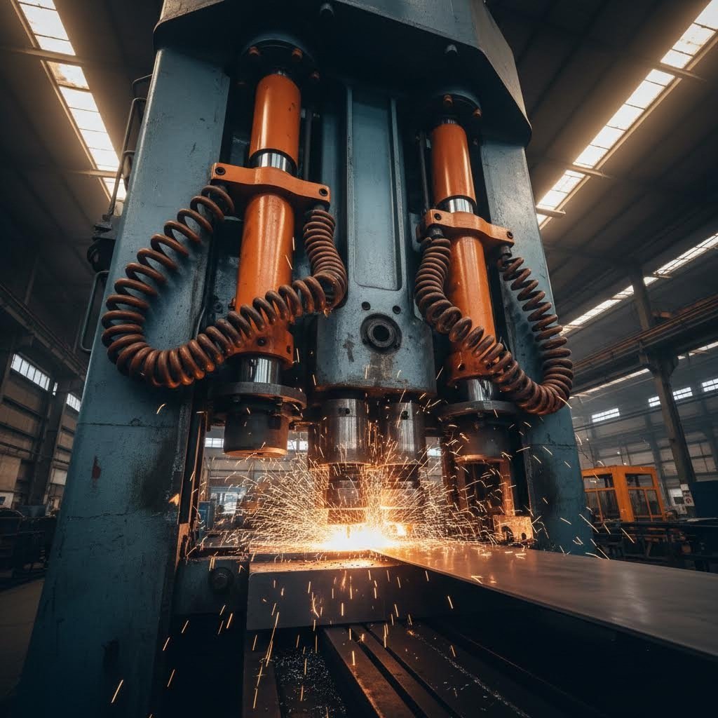
Kada se pritisak primijeni obično kroz hidraulične ili mehaničke prse, metal teče u šupljinu stvorenu između ovih usklađenih komponenti. Što je bilo s time? Dijelovi s preciznim dimenzijama, stalnom debljinom zida i izvrsnim kvalitetom površine.
Zašto je smrt bitna u suvremenoj proizvodnji
U proizvodnji, obloge služe kao ono što stručnjaci u industriji nazivaju "genetski kod kvalitete proizvoda". Izvanredni alat za izreziranje može pružiti preciznost na mikronovoj razini preko milijuna ciklusa, eliminirajući nedostatke poput krive stranice, dimenzionalnog pomicanja i površinskih nesavršenosti. Ova dosljednost izravno utječe na strukturalni integritet, životnost od umora i funkcionalnu pouzdanost gotovih komponenti.
Aplikacije obuhvaćaju gotovo svaku industriju koju možete zamisliti:
- Automobilska industrija: S druge konstrukcije, osim onih iz tarifne kategorije 8403
- Zrakoplovstvo: U skladu s člankom 6. stavkom 1.
- Potrošačke robe: S druge vrijednosti, osim onih iz tarifne oznake 8403
- Medicinski uređaji: Ostali proizvodi od metala
Što je to za ove industrije? Razmislite o ovome: ulaganje u precizne obloge u osnovi znači ulaganje u stabilnost kvalitete i reputaciju brenda. Dobro dizajnirana ploča se pretvara iz jednostavnog proizvodnog alata u strateško sredstvo koje određuje konkurentnu prednost na zahtjevnim tržištima.
Tijekom ovog članka, otkrićete devet kritičnih aspekata oblikovanja metala koje čak i iskusni inženjeri često zanemaruju, od izbora materijala i optimizacije procesa do novih tehnologija koje preoblikuju industriju.
S druge strane, u slučaju da se ne upotrebljava u proizvodnji, to znači da se ne upotrebljava u proizvodnji.
Izbor prave vrste matrice može pomoći ili uništiti vaš proizvodni projekt. S toliko mogućnosti, kako znate koje se stampiranje ili oblikovanje najprilagođenije uklapaju u vašu specifičnu primjenu? Odgovor ovisi o složenosti dijela, količini proizvodnje i potrebnim materijalima.
Razumijevanje različitih vrsta oblikovanja koje su dostupne pomaže inženjerima da donose informirane odluke koje poboljšavaju kvalitetu i troškovnu učinkovitost. Razdvojimo glavne kategorije obrada i istražimo kada svaka sjaji.
| Vrsta štampa | Glavno primjena | Raspon debljine materijala | Prilagodba obujmu proizvodnje | Razina složenosti |
|---|---|---|---|---|
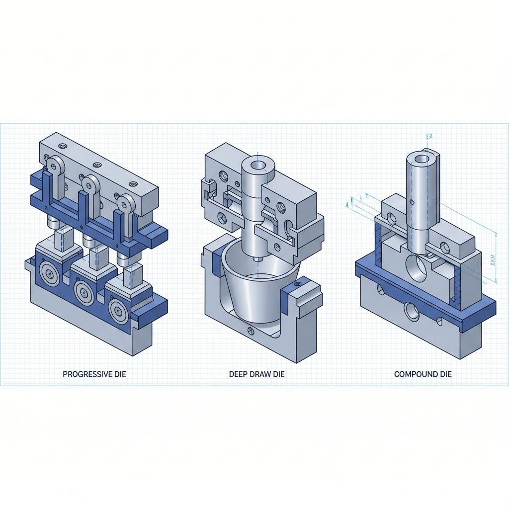
| Progresivne matrice | S druge strane, za proizvodnju električnih vozila s više karakteristika, ne smiju se upotrebljavati različiti uređaji. | S druge vrste | Veliki volumen (100.000+ dijelova) | Srednje do visoko |
| Prenos umre | S druge strane, za proizvodnju električnih vozila u kategoriji vozila iz točke 1.5.1. i 2.5.1. | Promenljiva na temelju dizajna | Kratke do duge vožnje | Visoko |
| Duboki vučeni alati | S druge površine, od plastičnih ili sintetičkih vlakana | Ovisi o omjeru povlačenja | Srednji do visoki volumen | Visoko |
| Složeni štampalići | S druge površine, od željeza ili čelika | S druge vrste | Srednji do visoki volumen | Niska do srednja |
| Matrice za oblikovanje | s druge strane, za proizvodnju električnih vozila, osim vozila iz točkova 85. i 85. | Varijabilno | Ukupna proizvodna količina | Srednji |
Sistemi progresivnog i transfernog izljevanja
Kada vi ste proizvodnja velikih količina malih i srednjih dijelova , progresivni umire postati vaš najbolji saveznik. Evo kako rade: metalna traka prolazi kroz niz stanica, s svakom stanicom koja dodaje drugačiju značajku - rez ovdje, savijanje tamo, rupu negdje drugdje. Do trenutka kada vaš dio dostigne konačnu postaju, on je potpuno formiran i spreman za razdvajanje.
Ljepota metalnog žigosanja u progresivnim konfiguracijama leži u njihovoj učinkovitosti. Prema Keats Manufacturing, ovaj pristup štedi vrijeme i novac obavljanjem više operacija istovremeno, a istovremeno smanjuje trošak otpada i troškove rada. Progresivni sustav štampača idealan je za dijelove poput zagrada, električnih kontakata i malih strukturnih dijelova koji zahtijevaju čvrste tolerancije.
Ali što se događa kada su vaši dijelovi preveliki ili složeni za napredne sustave? Tu se pojavljuju transferne ploče. Za razliku od progresivnih postavki u kojima radni dio ostaje pričvršćen na metalnu traku, prilikom prenošenja odjeljuje se pojedinačni dijelovi u ranom razdoblju procesa. Automatski mehanizmi zatim prenose svaki komad kroz više stanica, omogućujući operacije poput navojki, rebara i kvrga koji bi bili nemogući drugim metodama.
Transferne ploče su odlične za rukovanje:
- Sastavljeni proizvodi za proizvodnju električnih vozila
- Veliki dijelovi koji zahtijevaju fleksibilnost u rukovanju i usmjerenosti
- Kompleksni dizajn koji zahtijeva različite radnje u jednom proizvodnom ciklusu
- Proizvodnja cijevi i aplikacije koje zahtijevaju odvajanje radnog dijela
-Kakva je razmjena? Visoki operativni troškovi i dulja vremena postavljanja u usporedbi s progresivnim sustavima. Međutim, za složene geometrije i veće komponente, transferno stampiranje često predstavlja jedino održivo proizvodno rješenje.
Specijalistički oblikovanje kategorija
Osim progresivnih i prenosnih sustava, nekoliko specijaliziranih komponenti za obaranje obrađuje specifične izazove proizvodnje.
Složeni štampalići u slučaju da je proizvod u stanju da se koristi za proizvodnju, mora se upotrebljavati samo jedan proizvod. Zamislite da vam trebaju ravne perilice ili prazne dijelove kotača koji se proizvode na velikoj brzini s izvrsnom ponovljivom sposobnošću. Kompozicijski stamping daje upravo to, uz jeftinije alate od naprednih alternativa. Što je ograničeno? Oni su najprikladniji za jednostavnije, ravne dijelove umjesto složenih trodimenzionalnih geometrija.
Duboki vučeni alati u slučaju da se proizvod ne koristi za proizvodnju, proizvodnja se može provesti na temelju postupka: Motorske školjke, limenke za piće i kućišta za kućišta sve se oslanjaju na ovu tehniku. Proces zahtijeva pažljivo razmatranje svojstava materijala, posebno fleksibilnosti i smjera zrna, kako bi se spriječilo puktanje ili bore tijekom obrade.
Kuštarske matrice raditi pod još ekstremnijim uvjetima, preoblikujući metal kroz sile kompresije na povišenim temperaturama. Iako se tehnički razlikuje od metalnog štampiranja, razumijevanje kovanja pomaže inženjerima da cijene cijeli spektar opcija proizvodnje na bazi stampova.
Kovanje gume u slučaju da se ne primjenjuje primjenjivo visoki pritisak, za stvaranje finih, preciznih crteža s tolerancijama od ±0,01 mm. Kada su dimenzije, tekstura površine ili mali detalji u represiji važni, razmišljanje o preciznim konektorima ili detaljnim logotipovima postaje proces izbora.
Koju vrstu matrice biste trebali odabrati? Razmotrimo sljedeće čimbenike koji utječu na odluku:
- Obujam proizvodnje: U slučaju da se proizvodnja ne završi u skladu s ovim zahtjevima, potrebno je osigurati da se proizvodnja ne završi u skladu s ovim zahtjevima.
- Složenost dijela: Jednostavni ravni dijelovi odgovaraju složenim obradama; složeni dizajni zahtijevaju mogućnosti prijenosa
- Veličina dijela: Veće komponente obično zahtijevaju transferno stampiranje
- Ograničenja budžeta: Sastavljeni oblici pružaju niže troškove obrade alata; progresivni oblici pružaju bolju ekonomiju po dijelu u skali
Sa jasnim razumijevanjem ovih kategorija, sada ste spremni istražiti kako kompletan proces oblikovanja transformira koncepte u proizvodnu opremu.
Objasnjen kompletan proces oblikovanja matice
Izabrali ste pravu vrstu matrice za svoj projekt. Što sad? -Ne znam. Razumijevanje cijelog procesa izrade od početnog koncepta do validiranog proizvodnog alata odvaja uspješne projekte proizvodnje od skupih neuspjeha. Ipak, mnogi inženjeri potcjenjuju koliko sustavno ovo putovanje mora biti.
Smatrajte proizvodnju gume kao gradnju kuće: preskočite temeljne radove, i sve iznad toga postaje nestabilno. Svaka faza gradi na prethodnoj, a žurba kroz bilo koji korak stvara probleme koji se eksponencijalno povećavaju nizvodno. Prođimo kroz proces oblikovanja metala korak po korak.
- Sljedeći članak
Svaki uspješan projekt se započinje temeljnim pregledom Dizajn za proizvodnju (DFM). To nije samo provjeravanje da li vaš dio izgleda dobro na računaru, već određivanje da li se taj dizajn može pouzdano proizvesti u stvarnom svijetu.
Tijekom ove faze, inženjeri analiziraju vaše 3D modele i 2D crteže, ispitujući geometriju, specifikacije materijala, zahtjeve za debljinu i kritične tolerancije. Prema stručnjacima iz industrije GOHO Tech , provoditi dodatni tjedan u fazi DFM-a može uštedjeti šest tjedana kasnije modifikacija alata.
Što konkretno se procjenjuje?
- Kutovi izvlačenja: Vertikalni zidovi neće osloboditi od dieslight kutovi omogućiti čist dijelovi izbacivanje
- Uređaj za ispitivanje: Neudružljiva debljina uzrokuje deformaciju i koncentraciju napona
- Sastavljanje razdjelne linije: Strateško postavljanje smanjuje vidljive šavove na gotovim dijelovima
- Očekivani obujam proizvodnje: To utječe na strukturu, materijalni izbor i ukupne investicije
Nakon što je provedivost potvrđena, inženjeri za projektiranje kreiraju detaljne 3D modele koristeći specijalizirani CAD softver kao što su CATIA ili UG NX. Svaki dio je dizajniran - cipele, vodilice, udarci, šupljine, pritisak i podizanje. Ali evo što razlikuje moderne metode izrade alatnih ploča od tradicionalnih pristupa: virtualna provjera prije rezanja bilo kojeg čelika.
Računarski potpomognuti inženjerski (CAE) simulacijski softver kao što su AutoForm ili Dynaform djeluju kao kristalna kugla za proces proizvodnje oblikovanja. Inženjeri mogu točno predvidjeti kako će topljeni metal ili ploče teći, ispuniti šupljine i ohladiti. Moguće greške - zarobljavanje zraka, bore, prekomjerno tanjenje ili pukotine - postaju vidljive u digitalnom modelu.
Jedan automobilski projekt otkrio je simulacijom da bi zrak ostao zarobljen u kritičnom području zatvaranja, uzrokujući curenje. Testiranje tri različita dizajna vrata trajalo je gotovo jedan dan. Pronalaženje i popravak ovog problema nakon izgradnje fizičkog alata trajalo bi tjednima zavarivanja i ponovnog obrade.
- Izbor i obrađivanje čelika za alat
Sada digitalni dizajn postaje fizička stvarnost. Izbor materijala je ključan jer različite komponente izreznih materijala imaju različite razine napona i obrazace habanja. Jer što je proizvodnja gume ako ne umjetnost izbora pravog čelika za svaku primjenu?
Uobičajeni izbor od čelika za alat uključuje:
- H13 alatni čelik: Industrijski standard za odlijevanje na tjesnoću, pružajući odličnu otpornost na toplinski udarac
- D2, SKD11, Cr12MoV: S druge strane, za uređaje za proizvodnju električnih vozila, osim za uređaje za proizvodnju električnih vozila, ne smiju se upotrebljavati uređaji za proizvodnju električnih vozila.
- Tvrde pločice: Za područja s iznimno visokom opustošenjem koja zahtijevaju maksimalnu trajnost
Precizna obrada pretvara ove od čelika u funkcionalne komponente - Što? CNC freza se bavi urezanjem glavnih oblika, dok se elektromehaničkom strojnom obradom (EDM) bave finim detaljima, oštrim uglovima i dubokim rebrima do kojih se rotirajući rezači ne mogu doći. Tijekom procesa oblikovanja timovi za kontrolu kvalitete provjeravaju dimenzije pomoću koordiniranih mjernih strojeva (CMM) kako bi osigurali da svaka komponenta odgovara specifikacijama dizajna.
- Sastav i ispitivanje
Skupljenje je mjesto gdje vještini proizvođači gume sjaje. Smislite o tome kao o sastavljanju složene, teške, visoko precizne slagalice gdje svaki dio mora savršeno uklopiti. Bore, obaraju, zadržavaju, opruge, vodiče, sve se spaja pod iskusnim rukama koji provjeravaju poravnanost, razmak i glatko kretanje klizajućih komponenti.
Početna ispravka prati montažu. Tehnici nanose plave mrlje na površine koje se spajaju, pažljivo zatvaraju crtež i ispituju kako se površine uklapaju. Prilagođavanje ručnim brušenjem ili poliranjem osigurava ravnomjeran kontakt prije prvog stvarnog ispitivanja.
Onda dolazi T1 suđenje - trenutak istine. Sastavljeni obrtni materijal se instalira u testni tisk, metalni list prolazi kroz njega i prvi uzorci se pojavljuju. Inženjeri pažljivo promatraju proces, prilagođavajući postavke tiskanja poput tonaže, brzine i tlaka nad jastukom dok prave fine podešavanja da bi se uklonile bore, pukotine ili nedovoljna definicija.
- Uređenje i provjera proizvodnje
Proizvodnja dijelova je jedna stvar, dokazivanje da ispunjavaju specifikacije je druga. Strog pregled uključuje:
- Vizualna inspekcija: Provjeravajući da li postoje površni defekti, ogrebotine ili pukotine
- Svaka vrsta vozila mora biti opremljena s: Upotreba CMM-a, skenera i kontrolnih pribora za provjeru svih dimenzija koje se podudaraju s crtežima
- Analiza debljine materijala: U slučaju da se u području za uzgoj ne pojavi prekomjerno procijenjenje,
Ti se rezultati dokumentiraju u detaljnim izvješćima, često nazivanim izvješćima o inspekciji početnih uzoraka (ISIR), koji pružaju dokaze da proces oblikovanja metala dosljedno isporučuje dijelove koji su u skladu s specifikacijama.
- Kontrolna i prilagodba kvalitete
Validacija se ne završava prvim uspješnim dijelovima. Kontinuirana kontrola kvalitete osigurava da se proizvod održava tijekom cijelog životnog vijeka. To uključuje planirano održavanje, praćenje habanja i periodičnu provjeru dimenzija proizvedenih dijelova.
Od koncepta do proizvodnog uređaja
Svrha je da se osigura da se proizvodnja i proizvodnja proizvoda ne dovode u pitanje. Jednostavna složenost može trajati 8-12 tjedana, dok složena progresivna ili transferna može trajati 20-30 tjedana ili duže. Što je najvažnije? Jasna komunikacija u svakoj fazi i realna očekivanja postavljena tijekom početne faze planiranja.
Kritične kontrolne točke u razvoju
Gdje projekt obično krene po zlu? Iskustvo otkriva nekoliko kritičnih kontrolnih točaka kojima je potrebna posebna pozornost:
- Završena revizija DFM-a: Ne preskočite ovaj koraknepotpuni početni crteži uzrokuju tjedne prepravljanja nizvodno
- Svaka vrsta vozila Moderne CAE alatke otkrivaju 80-90% potencijalnih mana prije nego što se čelik reže
- Provjera materijala: Ulazne provjere kvalitete na čelik za alat sprečavaju prijevremeni neuspjeh obrade
- U slučaju da je to potrebno, provjera dimenzija mora se provjeriti. Uzimajući probleme ovdje košta mnogo manje nego otkrivanje ih nakon isporuke
Razumijevanje ovog sustavnog pristupa izrade obloge priprema vas za sljedeće kritično razmatranje: usklađivanje tehničkih specifikacija i kompatibilnosti materijala s vašim specifičnim zahtjevima za primjenu.
Tehničke specifikacije i kompatibilnost materijala
Dizajnirao si svoj dio i izabrao pravi tip matrice. Ali ovdje mnogi inženjeri zakasne: pretpostavljajući da će bilo koji materijal raditi u bilo kojoj operaciji oblikovanja. Stvarnost? Materijalna svojstva u osnovi diktiraju što je moguće postići u oblikovanju ploča, a ignoriranje tih ograničenja dovodi do puklih dijelova, prekomjerne stope otpada i frustriranih proizvodnih timova.
Razumijevanje odnosa između karakteristika materijala, dostižućih tolerancija i izbora čelika odvaja uspješne projekte od skupih neuspjeha. Razmotrićemo tehničke specifikacije koje određuju uspjehu ili neuspjeh vašeg obrta.
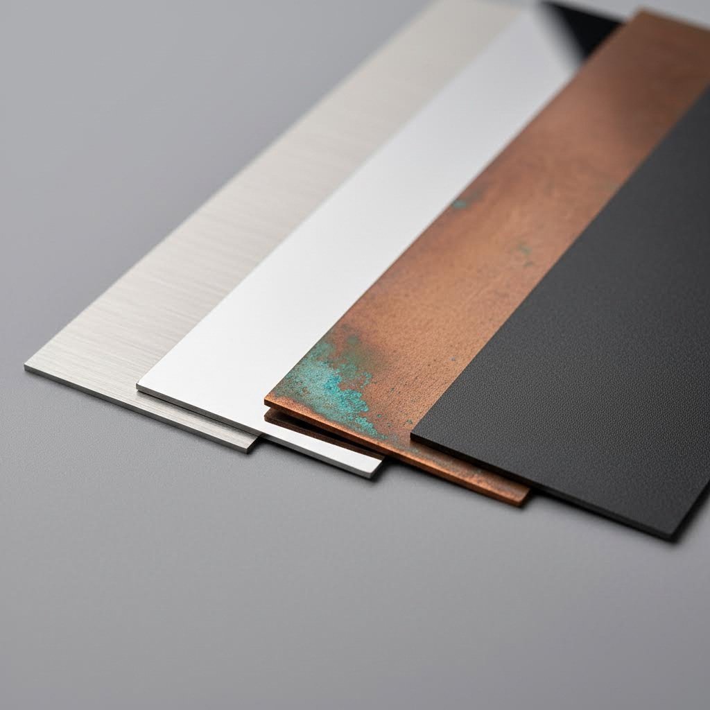
Kriteriji za odabir materijala za oblikovanje
Ne ponašaju se svi metali isto pod pritiskom. Proces oblikovanja ploče zahtijeva pažljivo razmatranje tri kritična svojstva materijala:
- Mehanizam otpora: Određuje snagu potrebnu za oblikovanje materijala i utječe na zahtjeve za kapacitet štampe
- Duktibilnost: Mjere koliko se metal može isteći prije puktanjakritično za operacije dubokog crtanja
- Smjer zrna: Utječe na kvalitetu savijanja i potencijal pukotina rubova tijekom oblikovanja
Prema stručnjacima za proizvodnju u Gunna inženjering , fleksibilnost, rastegljivost i oblikovitost metala značajno se razlikuju ovisno o njihovim svojstvima. Zbog toga su neki materijali manje-više pogodni za duboko oblikovanje. U skladu s člankom 3. stavkom 1. točkom (a) Uredbe (EU) br. 528/2012 Komisija je odlučila da se odluka o uvođenju mjera odredi u skladu s člankom 3. stavkom 1. točkom (a) Uredbe (EU) br. 528/2012.
Koji materijali najbolje odgovaraju različitim operacijama oblikovanja? Evo glavnih kandidata:
- Ugljikov nafta: Odlična oblikljivost s dobrim omjerom snage i troškova; idealna za automobilske nosile, strukturne komponente i opće metalne ploče
- Nerustingajući čelik: Veća čvrstoća, ali manja fleksibilnost; zahtijeva strože tolerancije i veću silu za oblikovanje
- Legure aluminija: Mekan i vrlo fleksibilan; dopušta umjerene tolerancije (± 0,1 mm tipično za savijanja) i dobro radi za zrakoplovnu industriju i potrošačku elektroniku
- Bakrene legure: Izvanredna električna i toplinska provodljivost; dopušta umjerene tolerancije i odgovara električnim spojevima i toplotnim razmjenjivačima
- Specijalni metali: Titanijev i alatni čelik zahtijevaju iznimno strogu kontrolu tolerancije zbog niske fleksibilnostititanij obično održava kutne tolerancije od ± 0,5° za savijanja
Evo praktičnog uvida: kada inženjeri pokušaju kovati metal na materijalima s nedovoljnom fleksibilnošću, rezultati uključuju pukotine površine i nedosljedne dimenzije. Za kovljenje ploča potrebno je materijala koji mogu izdržati iznimno visok pritisak bez frakture. Najbolje se ponašaju čelikovi s niskim udjelom ugljika ili mekane bakarne legure.
Sposobnosti i ograničenja tolerancije
Tolerancije u obradnji na listu nisu proizvoljni brojevi, one predstavljaju "precizni ugovor" koji određuje da li se dijelovi pravilno sastavljaju, pouzdano funkcioniraju i ispunjavaju standarde kvalitete. Prema specifikacijama tolerancija iz ADH Machine Tool-a, primjena nepotrebno uskih geometrijskih tolerancija značajno produžava vrijeme trajanja i povećava složenost i troškove proizvodnje.
Koje tolerancije možete realistično postići? Debljina materijala igra odlučujuću ulogu:
| Vrsta materijala | Tolerancija debljine | Izravno izravno | Izravno izravno izravno |
|---|---|---|---|
| Legura aluminija (6061-T6) | ±0,05 mm | svaka vrsta vozila | ±0.1 mm |
| Nerđajući čelik (304) | ±0,05 mm | ±0.5° | ±0.1 mm |
| Ugljikovodni čelik (1018) | ±0,05 mm | ±0.5° | ±0.1 mm |
| Sklonica bakra (C11000) | ±0,05 mm | svaka vrsta vozila | ±0.1 mm |
| Alatni čelik (D2) | ±0.02 mm | ±0.25° | ±0,05 mm |
Zašto je to važno za vaš dizajn metalnih matica? Uzmimo za primjer "springback" - sklonost materijala da se nakon savijanja djelomično vrati u svoj izvorni oblik. Visoko čvrsti materijali imaju izraženiji povrat, što zahtijeva namjerno pregijanje kako bi se postigli ciljani uglovi. Moderne pritisak kočnice nadoknaditi sagnuće na 88,5 ° kada cilja 90 °, na primjer.
Smjer zrna predstavlja još jedno često zanemareno razmatranje. Pozicioniranje linija savijanja pravougaono na smjer zrna materijala minimizira mikro pukotine na vanjskim površinama savijanja. Ignoriranje ove veze dovodi do prijevremenog kvaru dijela tijekom rada.
Izbor i proizvodnja čelika za izbijanje
Tvoj metalni materijal je samo dobar kao čelik od kojeg je napravljen. Prema proizvodnim podacima iz Protolabs , alatni čelik sadrži 0,51,5% ugljika plus legirajuće elemente kao što su hrom, vanadij, volfram i molibden koji formiraju karbide koji pružaju iznimnu tvrdoću i otpornost na habanje.
Koji čelik odgovara vašoj aplikaciji?
- S druge strane, u skladu s člankom 3. stavkom 1. Najveća otpornost na habanje za obaranje abrazivnih materijala kao što su nerđajući čelik ili čelik visoke čvrstoćeidealno za obaranje ploča koje zahtijeva produženo proizvodno razdoblje
- H13 toplotno obrađivani čelik (45-55 HRC): Održava čvrstoću na temperaturama do 540 °C; polira do ogledala za estetske dijelove
- S druge strane, u skladu s člankom 3. stavkom 1. U skladu s člankom 3. stavkom 2. točkom (a) ovog članka, za sve uređaje za opću uporabu, potrebno je upotrebljavati:
- S7 otporan na udare čelik (54-58 HRC): Uzima udarne opterećenja bez puktanjaod ključnog značaja za stampiranje i za teške primjene
Pri proizvodnji dijelova s abrazivnim materijalima, uključujući čelične materijale visoke čvrstoće, opruge i superlegure, potrebni su alati vrhunske kvalitete od čeličnog čelika ili čvrstog karbida. Troškovi obrade alatke rastu, ali i dugotrajnost proizvodnje često se povećava za 3-5 puta u usporedbi s standardnim čelikovima.
Površinski tretmani produžavaju životni vijek. Opcije uključuju premaze karbidnim titanom, specijalizirane dupleksne premaze i nitridne tretmane koje smanjuju trenje i štite od habanja. U slučaju proizvodnje velikih količina veće od 500.000 ciklusa, te se investicije obično isplaćuju smanjenim održavanjem i stalnom kvalitetom dijelova.
Sada kad su kompatibilnost i tolerancija materijala jasna, spremni ste istražiti specifične operacije oblikovanja - savijanje, flansiranje, kovljenje i graviranje - koje pretvaraju ravnu ploču u funkcionalne komponente.
Uređivanje operacija i tehnika u obradi
Razumijevanje različitih vrsta matrica i kompatibilnosti materijala vas dovodi na pola puta. Ali što je sa samom operacijom stvaranja? Svaka tehnika - savijanje, obrezivanje, obrezivanje, kovljenje i graviranje - zahtijeva svoj pristup, konfiguraciju alata i parametre procesa. Ako izaberete pogrešnu metodu za svoju primjenu, to stvara probleme od neskladnih uglova do puklih površina.
Razmotrićemo specifične operacije oblikovanja ploča koji pretvaraju ravnu materijal u funkcionalne trodimenzionalne komponente. Otkrit ćete koja tehnika odgovara svakoj primjeni i zašto neke operacije oblikovanja metala koštaju znatno više od drugih.
| Vrsta operacije | Tipične primjene | Složenost alata | Kvaliteta površinske obrade |
|---|---|---|---|
| Zrakovanje | Protiprovi, proizvodnja u malom obimu, dijelovi koji zahtijevaju više uglova | Niska | Dobar |
| Potpuno oblikovanje (Bottoming) | Srednja proizvodnja koja zahtijeva konzistentne kutove | Srednji | Vrlo dobro |
| Otpremanje | Precizni dijelovi, dijelovi s ograničenim tolerancijama, fini detaljni rad | Visoko | Izvrsno |
| Rubno oblikovanje | U skladu s člankom 3. stavkom 2. | Srednji | Dobar |
| Zavijanje rubova | S druge strane, proizvodi od metala ili od drugih materijala | Srednje do visoko | Izvrsno |
| Embosiranje | S druge strane, za proizvodnju proizvoda iz poglavlja 94. točka (a) ovog članka ne vrijede: | Srednji | Vrlo dobro |
| Sastavljanje gumenih podloga | Komponente za zrakoplovstvo, složene krivulje, proizvodnja prototipa | Niska do srednja | Izvrsno |
Proizvodnja i proizvodnja električne energije
Izgibanje predstavlja najprirodniji oblikovni postupak u obradi ploča. Princip zvuči jednostavno: "Pretaknite metal oko ravnoj osi dok ne dobije novi oblik". Ipak, izvršavanje uključuje kritične odluke koje određuju kvalitetu dijela, troškove proizvodnje i dugovječnost alata.
Tri različite metode savijanja dominiraju u industriji, od kojih svaka ima jedinstvene karakteristike:
Zrakovanje nudi maksimalnu fleksibilnost uz minimalnu ulaganje u alat. Prema tehničkoj dokumentaciji iz Inductaflex , u ovoj metodi udarac gura list na pola u V-tvornicu, dodirujući samo vrh udarca i gornje rubove tvornice. Dubina udarca, a ne ugao, određuje konačni ugao savijanja.
Zašto proizvođači za određene primjene preferiraju savijanje zraka?
- Za formiranje je potrebna manja sila od alternativnih metoda
- Jedna matica upravlja više uglova kroz prilagođavanje udarca
- Uređaji traju duže zbog smanjenog pritiska kontakta
- Vreme postavljanja ostaje kraće za različite serije proizvodnje
-Kakva je razmjena? Springback predstavlja najveći izazov. Ovisno o leguri i polumjeru, povratna sila u zračnom savijanju može biti veća od 5°, posebno u tvrđim materijalima kao što je aluminij 6061-T6. Za nadoknadu tog elastičnog oporavka potrebno je točno programiranje ili ručna korekcija.
Potpuno oblikovanje (Bottoming) pruža veću točnost kada je ponavljanje važnije od fleksibilnosti. Udarac pritiska materijal dok se čvrsto ne osloni na obje strane, što će se približiti uglu. Ovaj čvršći kontakt smanjuje povrat u otpornost na približno 1° do 2° u većini primjena.
Međutim, dno zahtijeva posebnu alatku za svaki kut za savijanje i zahtijeva znatno veću tonažu tiska. U skladu s člankom 3. stavkom 2. točkom (a) ovog članka, u slučaju da se proizvodnja ne završi u skladu s člankom 3. stavkom 1. točkom (a) ovog članka, proizvođač mora se obratiti na proizvodnju koja se završava u skladu s člankom 3. točkom (b) ovog članka.
Sljedeći članci s druge strane, u slučaju da se ne upotrebljava, to znači da se ne upotrebljava samo za proizvodnju proizvoda iz kategorije 9A001. Tri varijante flange odgovaraju različitim proizvodnim potrebama:
- Srednja visina: Sastavljanje i održavanje
- -Pretkavanje. Formira konveksne krivulje gdje se vanjski rub proteže tijekom formiranja
- Smanjenje: Stvara konkavne krivulje gdje se materijal komprimira na rubu
Hemming dalje vodi flanging tako što previja rub potpuno natrag na sebe - ili ravno na ploči ili s malim raskorakom. Automobilski vrata i rubovi uređaja obično imaju obručene rubove koji eliminišu izloženost oštrim metalima, a dodaju krutost.
Tehnike kovanja i preciznog oblikovanja
Kad se tolerancije zatvore i kada je površno izrađivanje kritično, tehnike oblikovanja i kovljenja metala pružaju rezultate koje standardno savijanje jednostavno ne može postići.
Kaljenje savijanjem - primjenjuje ekstremni pritisak, najviši među svim metodama savijanja, kako bi stisnuo materijal na dno šupljine. Prema istraživanju Inductaflex-a, deformacija je plastična, a ne elastična, što znači da oblik drži nakon oblikovanja bez skoro nikakve povratne oblike.
Što čini kovanje pravim izborom za zahtjevne primjene?
- Isporučuje tačne uglove s gotovo nula springback
- Odličan za teške temperamente ili male zavojnice.
- Proizvodi ponavljajuće rezultate čak i u dijelovima s ograničenom tolerancijom
- Stvara fine detalje površine nemoguće s drugim metodama
Točnost ima svoju cijenu. U slučaju da se u slučaju izbijanja upotrijebi metoda "izbijanja" ili "izbijanja" u skladu s člankom 3. stavkom 1. točkom (a) ovog članka, potrebno je utvrditi da je u slučaju izbijanja upotrijebljena metoda "izbijanja" ili "izbijanja" u skladu s člankom 2. točkom (b Ovo tanjenje može smanjiti otpornost na umor u nekim primjenama, što čini kovljenje nepraktičnim za deblje listove osim ako nisu dostupne velike tiskare.
Embosiranje ne može se koristiti za proizvodnju odjeće za proizvodnju odjeće. U oblikujućem materijalu se odrazima odlikuju detaljni oblici - logotipi, dekorativne teksture ili strukturna ojačana rebra - kroz kontroliranu deformaciju. Za razliku od kovanja, ugraviranje obično uključuje manje ekstremnih pritisaka i fokusira se na estetiku površine, a ne dimenzionalnu preciznost.
Sastavljanje gume za specijalne primjene
Ponekad čvrste čelične obloge nisu rješenje. U oblikuju gomila pad koristi fleksibilnu podloge tipično poliuretana ili guma kao polovicu oblikovanja matice. Lasta se pritisne između ove otporne podloge i čvrste obloge, omogućavajući složene krivulje i konture bez odgovarajućeg čelika.
Prema podacima o industrijskim primjenama iz PSI Urethanes u skladu s člankom 3. stavkom 1. Zbog većeg otpornosti na vladanje, veće otpornosti na abraziju i boljeg nosivosti, poliuretanske podloge postali su omiljeni proizvodi za industriju koja zahtijeva trajna rješenja. Ova tehnika posebno koristi zrakoplovstvu za oblikovanje lakih komponenti složenih geometrija.
Zašto razmisliti o oblikovanju gumenih podloga za vašu primjenu?
- Niži troškovi alata: Samo jedan čvrsti blok oblika potreban umjesto podudarnih setova crteža
- Odlično završetak površine: Fleksibilni podloga spriječava ogrebotine i marring
- Sposobnost složene geometrije: Formira složenom krivulje koje bi zahtijevale skupe progresivne umiru inače
- Smanjeno vrijeme podešavanja: Brza promjena između različitih konfiguracija dijelova
Poliuretan posebno nadmašuje tradicionalnu gumu zbog poboljšane apsorpcije energije i otpornosti. To poboljšava preciznost u procesu oblikovanja, a istovremeno smanjuje greške. Industrije od automobilske do građevinske koriste te materijale za primjene u kojima bi standardno oblikovanje matrica bilo nepraktično ili jeftino.
Izbor između ovih vrsta oblikovanja ovisi o vašim specifičnim zahtjevima: količini proizvodnje, zahtjevima tolerancije, očekivanjima završne površine i ograničenjima proračuna. Zračno savijanje odgovara prototipiranju i raznovrsnoj proizvodnji; dno se drži dosljednim srednjim količinama; i kovanje postaje nužno kada se preciznost ne može ugroziti.
S operacijama oblikovanja sada shvaćenih, sljedeća razmatranja postaju jednako kritična: kako suvremena tehnologija - CNC integracija, automatizacija i koncepti Industrije 4.0 - transformišu ono što je moguće u proizvodnji oblikovanja.
Moderna tehnologija u proizvodnji kalupnih obloga
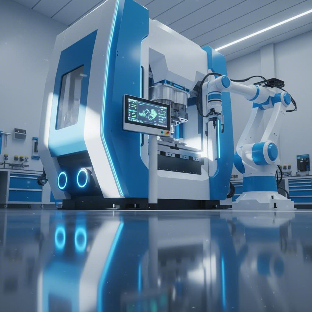
Ovladao si operacijama oblikovanja... savijanje, kovanje, obručenje. Ali evo što razlikuje dobre proizvođače od velikih: iskorištavanje tehnologije koju konkurenti nisu ni razmotrili. Dok tradicionalne štampe još uvijek dominiraju mnogim objektima, moderna proizvodnja oblikovanja prošla je kroz tihu revoluciju. Servo-pokretni sustavi, automatizirano rukovanje materijalom i detekcija u realnom vremenu sada pružaju mogućnosti koje su se činile nemogućim prije samo deset godina.
Što to znači za vaše operacije oblikovanja? Brži ciklusi, strože tolerancije i dramatično smanjene stope otpada. Razmotri kako te tehnologije preoblikuju ono što je moguće postići s strojevima i automatiziranim proizvodnim sustavima.
CNC integracija u moderne sisteme za obaranje
Tradicionalne mehaničke mase rade na fiksnim profilima pokreta - ovratnik se kreće na unaprijed određene brzine bez obzira na to što oblikujete. Servo-presovi mijenjaju sve. Prema proizvodnim stručnjacima u Šuntec Press , servo-presovi koriste programirane servomotore za pokretanje ovratnika, pružajući potpunu kontrolu kretanja tijekom cijelog poteza.
Što čini ovu tehnologiju transformativnu? Razmotrimo sljedeće mogućnosti:
- Profili promjenjivih udarca: Brzi pristup, sporo pritisak, kontrolirani boravak i brz povrataksve programirajuće za svaki specifičan dio
- Smanjena deformacija dijela: Nežno oblikovanje smanjuje povratak i površne defekte
- Produženi vijek trajanja kalupa: Glatko, kontrolirano kretanje s smanjenim udarom na donji mrtvi centar smanjuje udarac i stres na proizvodnom alatu
- Smanjenje potrošnje energije: Servomotori koriste energiju samo u pokretu, smanjujući troškove energije za 30-50% u usporedbi s sustavima s malim kotačem
Prednost preciznosti posebno je značajna za složene obrade. Za razliku od konvencionalnih sustava gdje prihvatate bilo koji profil pokreta koji pruža volan, mašinsko rezanje sa servom omogućuje inženjerima da optimiziraju svaku milisekundu ciklusa udara. Trebaš usporiti kroz kritičnu zonu stvaranja da bi spriječio pukotine? Programiraj ga. Želite brže povratne poteze za povećanje produktivnosti? I to je podešavajuće.
Regenerativno kočenje dodaje još jednu dimenzijuservo sustavi hvataju energiju tijekom usporavanja i vraćaju je u napajanje. U slučaju proizvodnje velikih količina koja se dnevno provodi tisućama ciklusa, te uštede se povezuju s znatnim smanjenjem operativnih troškova.
Automatizacija i pametno proizvodnje
Osim same tiskarske strojeve, moderno oblikovanje se integriše u šire automatizirane sustave koji minimiziraju ljudsku intervenciju uz maksimiziranje dosljednosti. Automatsko rukovanje materijalomhrane za zavojnice, mehanizmi za prijenos i robotizirano izvlačenje dijelovadrže proizvodnju u toku bez ručnog učitavanja između ciklusa.
Ali prava transformacija dolazi od integracije industrije 4.0. Današnji napredni strojevi za obaranje uključuju:
- Stvarno-vremenski nadzor: Senzori neprekidno prate tonažu, položaj udarca i vrijeme ciklusa, upozoravajući operatere na odstupanja prije nego se pojave nedostatci
- Prediktivno održavanje: AI algoritmi analiziraju uzorke vibracija i performanse kako bi se održavanje zakazalo prije nego što se dogode kvarovi
- Slijedeći postupci: U-die detekcija provjerava dimenzije dijela tijekom proizvodnje, automatski odbacuje izvan specifikacije dijelove
- Digitalna povezanost: Proizvodni podaci se prenose na sustav poduzeća za sveobuhvatnu analitiku i optimizaciju procesa
Koje opipljive koristi donosi ova automatizacija? Rezultati govore jasno:
- Smanjeno vrijeme ciklusa: Uklanjanje ručnog rukovanja između operacija smanjuje ukupno vrijeme proizvodnje za 25-40%
- Konzistentna kvaliteta: Automatizirani sustavi ne umiru, ne ometaju se, niti mijenjaju tehniku. Svaki ciklus ide identično.
- Niži troškovi rada: Jedan operater može nadzirati više automatiziranih stanica umjesto ručnog napajanja pojedinačnih tiskara
- Poboljšana sigurnost: Držajući ruke podalje od pokretnih strojeva, radno ozljede se znatno smanjuju
Sposobnosti brzog izrade prototipa slično su ubrzale razvojne cikluse. Ono što je ranije zahtijevalo tjedne ručnog prilagođavanja, sada se događa u nekoliko dana. Inženjeri virtuelno simuliraju obrade oblikovanja, potvrđuju dizajne kroz CAE analizu i proizvode prototipne dijelove na fleksibilnim servosustavima - sve prije nego što se odluče za tvrdo proizvodno oruđe.
Prema istraživanju Shuntec Press, servo-presure opremljene algoritmima za kontrolu pod utjecajem umjetne inteligencije automatski mogu prilagoditi profile pokreta na temelju povratne informacije o materijalu ili promjenljivih procesa. Ova prilagodljivost poboljšava točnost oblikovanja i smanjuje ljudske pogreške, čime se operacije čine učinkovitijim i dosljednijim u različitim proizvodnim uvjetima.
Trend minijaturizacije također nastavlja preoblikovati industriju. Kompaktni servo-presovi sada služe za čiste prostorije i specijalizirane primjene u medicinskoj i mikroelektronskoj proizvodnji, gdje bi tradicionalni hidraulički sustavi bili nepraktični zbog zabrinutosti zbog kontaminacije ili ograničenja podnog prostora.
S obzirom na to da su tehnološke mogućnosti sada jasne, pojavljuje se sljedeće kritično pitanje: koliko zapravo košta sva ova ulaganja i kada povrat opravdava troškove?
Analiza troškova i povrat ulaganja za alatke za oblikovanje na tjesnoću
Istraživali ste tipove crteža, savladali operacije oblikovanja i otkrili vrhunske tehnologije automatizacije. Ali evo pitanja koja će na kraju odrediti da li će vaš projekt napredovati: koliko će to zapravo koštati i kada se ulaganje isplati? Čudno je da mnogi inženjeri zanemaruju cjelokupnu financijsku sliku, usredotočavajući se na početne cijene alata, a ignoriraju faktore koji zaista pokreću dugoročnu profitabilnost.
Razumijevanje ekonomije proizvodnje alata i obrada štampara razdvaja uspješne projekte od budžetskih katastrofa. Razmotrićemo točno što pokreće troškove, kako izračunati značajan povrat, i kada je oblikovanje iz formiranja najisplativija opcija.
Razumijevanje ulaganja u strojeve za obaranje
Što je zapravo ulaganje u alat i obloge? Prva cijena koju dobijete predstavlja samo vidljivi dio ukupnih troškova. Sveobuhvatna analiza troškova mora obuhvatiti svaku fazu od koncepta do validacije proizvodnje.
Primarni troškovi uključuju:
- Inženjering i dizajn: CAD modeliranje, simulacija CAE, revizija projektiranja za proizvodnju i izmjene inženjerstva obično 10-15% ukupnih troškova alata
- S druge konstrukcije od čelika Uvođenje sirovina, CNC obrada, radovi EDM-a, brušenje i toplinska obrada često 50-60% ukupnih ulaganja
- Proba i validacija: Vreme tiskanja, proizvodnja uzoraka, inspekcija dimenzija, prilagodbe i odobrenja kupacapribližno 15-20% troškova projekta
- Uređivanje: Preventivno održavanje, zamjena elemenata koji su se pokvarili i periodična obnova često su zanemareni, ali ključni za točna izračunavanja ROI-a
U skladu s analizom troškova proizvodnje iz Mursixa, kreiranje prilagođenih matica obično predstavlja najznačajniji početni troškovi, ali nakon što je matica proizvedena, cijena po jedinici značajno se smanjuje s većim proizvodnim redovima. Zbog te ekonomske stvarnosti za točno planiranje neophodne su procjene količine.
Kompleksnost materijala dramatično utječe na zahtjeve za ulaganjem. Jednostavna slojena matrica za ravne perilice može koštati od 5.000 do 15.000 dolara, dok složena progresivna matrica s više od 20 stanica za automobilske nosile može biti veća od 150.000 dolara. Prenosni oblici za velike, složene komponente ponekad dostižu 300.000 dolara ili više. Svaki proizvođač matrice procjenjuje složenost na temelju broja operacija, zahtjeva za tolerancijom i očekivanih količina proizvodnje.
Izbor materijala također značajno utječe na troškove. Obični materijali poput aluminija ili čelika zahtijevaju standardne pristupe alatima, dok specijalne legure ili deblji materijali zahtijevaju vrhunske opskrbe maticama tvrđe alate od čelika, specijalizirane premaze i robusnija konstrukcija koja povećava početne ulaganje.
Izračunavanje povrata ulaganja u alat
Kada se vaša ulaganja u proizvodnju materijala zapravo isplate? Odgovor ovisi o količini proizvodnje, složenosti dijelova i alternativnim proizvodnim mogućnostima.
Prema istraživanju ROI-a iz Pivatic-a, tradicionalne formule ROI-a pružaju osnovni okvir, ali operacije s listom metala zahtijevaju nuanciraniju analizu. Dobici proizvodnje iz automatizacije mogu dramatično utjecati na izračune ROI-a, jer su moderna rješenja za proizvodnju utjecala na više aspekata proizvodnje istovremeno.
Uzmimo za primjer sljedeće usporedbe za grupu koja zahtijeva 100.000 jedinica godišnje:
| Faktor cijene | Sastavljanje i proizvodnja | Lasersko rezanje + savijanje |
|---|---|---|
| Ulaganje u opremu | $75,000 | $2.000 (samo za igre) |
| Proizvodnja | $0.35 | $2.50 |
| Godišnje troškove proizvodnje (100.000 jedinica) | $35,000 | $250,000 |
| Točka izravnati troškove | ~35.000 jedinica | N/A |
| ukupni troškovi za pet godina | $250,000 | $1,252,000 |
Brojke otkrivaju zašto je oblikovanje na formiranju dominiralo proizvodnjom velikih količina. Unatoč značajnim početnim ulaganjima u komplete za tiskanje, dramatično niže troškove za svaki dio stvaraju uvjerljivu ekonomiju u obimu. Do druge godine, postupni metod je uštedio preko 400.000 dolara u usporedbi s alternativnim metodama.
U skladu s člankom 3. stavkom 2.
- Jednostavan spoj: 4-8 tjedana vremena, minimalna promjena postavke
- Postupne matrice: 12-20 tjedana vremena, 2-4 sata tipične postavke
- Transfer kalupi: u slučaju da je potrebno više od jednog radnog dana, potrebno je osigurati da se ne smanji radni sat.
- Svaka vrsta materijala za proizvodnju: u slučaju da je primjena primjene ograničena, primjenjuje se sljedeći postupak:
Ugrađena proizvodnja prema vanjskoj proizvodnji
Treba li se proizvoditi matice unutar ili partnerstvo s specijaliziranim proizvođačima alatke? Ekonomika ovisi o količini proizvodnje, inženjering sposobnosti, i strateške prioritete.
Ugrađena proizvodnja matice ima smisla kada imate:
- U skladu s člankom 3. stavkom 1.
- Sposobni radnici za izradu alata i obrada
- Kriticna pitanja intelektualne svojine
- U skladu s člankom 3. stavkom 1.
Izvršni poduzeća obično su ekonomičnija kada:
- Potrebe za alatom su povremene ili vrlo promjenjive
- Potrebne su specijalizirane sposobnosti (velike progresivne obloge, složeni sustavi prijenosa)
- Ulozi u ulaganje u opremu
- Osnovne kompetencije nalaze se negdje drugdje u lancu vrijednosti
Prema razmatranjima troškova uvoza iz Mohawk Global u skladu s člankom 3. stavkom 1. ovog članka, tvrtke koje vanjske tvrtke poduzimaju proizvodnju moraju također obračunati "pomoćne" procjene. U skladu s člankom 2. stavkom 2. točkom (a) Uredbe (EZ) br.
Kada je oblikovanje na formiranju troškovno učinkovito u usporedbi s alternativama poput laserskog rezanja, vodenih zraka ili obrade? U skladu s člankom 3. stavkom 2. točkom (a) ovog članka, za proizvodnju električne energije u Uniji primjenjuje se sljedeći standard: Ulaganja u obradu strojeva na izbacivanje postaju teže opravdati ispod tog praga, dok se količine koje premašuju 100.000 jedinica gotovo uvijek favorizuju pristupi istikobljenja.
Razumijevanje ove dinamike troškova omogućuje vam donošenje informiranih odluka o ulaganjima u proizvodnju. Međutim, troškovi nisu važni ako se ne razmotri gdje će se ti dijelovi koristiti.
Uređaji za proizvodnju i proizvodnju električnih vozila
Analizirali ste troškove, izračunali povrat novca i razumjeli financijsku logiku iza ulaganja u formiranje. Ali ovdje se teorija susreće s stvarnošću: kako stvarna industrija primjenjuje ove tehnike za rješavanje stvarnih izazova proizvodnje? Svaki sektor - automobil, zrakoplovstvo, elektronička oprema i elektronika - zahtijeva jedinstvene specifikacije, tolerancije i certifikata kvalitete koji temeljno oblikuju strategije dizajna i proizvodnje.
Razumijevanje tih zahtjeva specifičnih za industriju pomaže inženjerima da određuju alate koji ispunjavaju zahtjevne standarde primjene uz optimizaciju troškovne učinkovitosti. Razmotri kako metalni formiranje transformira sirovine u kritične komponente u različitim sektorima.
| Industrija | Tipični dijelovi | Zahtjevi za volumenom | Standardi kvalitete |
|---|---|---|---|
| Automobilski | U slučaju vozila s brzinom od 300 km/h, za vozila s brzinom od 300 km/h, za vozila s brzinom od 300 km/h, za vozila s brzinom od 300 km/h, za vozila s brzinom od 300 km/h i za vozila s brzinom od 300 km/h, za vozila s brzin | 100.000 - 1.000.000+ godišnje | U skladu s člankom 4. stavkom 1. |
| Zrakoplovstvo | Svaka vrsta vozila s motorom | 1000 - 50.000 godišnje | U skladu s člankom 6. stavkom 1. |
| Elektroprilog | S druge strane, za proizvodnju električnih vozila, ne smiju se upotrebljavati električni uređaji za proizvodnju električnih vozila. | 50.000 - 500.000 godišnje | ISO 9001, UL certifikat |
| Elektronika | Uređaji za proizvodnju električne energije | 500.000 - 10.000.000+ godišnje | ISO 9001, IPC standardi |
Primjene automobila
Kad pomislite na oblikovanje metala u velikim razmjerima, automobilska industrija odmah vam pada na pamet. Moderna vozila sadrže stotine utisnutih dijelova - od vidljivih ploča karoserije koje zahtijevaju površinske završetke klase A do skrivenih strukturnih zagrada koji zahtijevaju precizne dimenzijske tolerancije. Koja je uloga rezanja ovdje? Osim jednostavnih operacija praznog otiska, automobilarna štampa obuhvaća složene progresivne sisteme koji proizvode sve od šarenice vrata do štitova za spremnike goriva.
Dijelovi na koje se proizvođači automobila oslanjaju uključuju:
- Svaka od sljedećih opcija: Čestice koje zahtijevaju iznimnu kvalitetu površine za bojenje
- Konstrukcijski Elementi: B-stočci, podni dijelovi, križani članci komponente za koje su čvrstoća i učinak na udaranje važniji od izgleda
- Čestice pogonskog sustava: Funkcionalne komponente koje zahtijevaju stroge tolerancije i dosljedna svojstva materijala
- Sigurnosni sustavi: U slučaju da je to moguće, mora se provjeriti da je to moguće.
Zašto proizvođači automobila zahtijevaju tako stroge sustave kvalitete? Prema OGS Industries, IATF 16949 certifikat ide dalje od osnovnih zahtjeva ISO 9001 kako bi se osigurala usklađenost s načelima štednje proizvodnje, prevencijom mana, odvraćanjem varijansi i smanjenjem otpada. Za operacije obaranja i oblikovanja metala, ova potvrda pokazuje posvećenost isporuci dosljednih komponenti u skladu s specifikacijama.
U skladu s člankom 3. stavkom 1.
- Konzistentna kvaliteta: Proučavanje i mjerenje procesa povećavaju produktivnost i pružaju ponovljive rezultate
- Smanjena varijacija proizvoda: U skladu s člankom 4. stavkom 2.
- Sprječavanje grešaka: Isprobani i dokazani proizvodni procesi smanjuju neučinkovitost i smanjuju nedostatke prije nego što stignu na proizvodne linije
- Pouzdan lanac opskrbe: IATF 16949 utvrđuje kriterije za nabavku dobavljača, stvarajući jače i pouzdanije odnose
Za proizvođače koji traže precizna rješenja za pecanje koje ispunjavaju standarde automobila, mogućnosti su izuzetno važne. U skladu s člankom 3. stavkom 2. Brzo izradu prototipa ponekad isporuku uzoraka u samo pet dana ubrzava razvojne vremenske linije koje su se ranije trajale mjesecima. A visoka stopa odobrenja za prvi prolaz koja premašuje 90% smanjuje skupe cikluse iteracije uz održavanje proizvodnih rasporeda.
Zanima li vas istraživanje sveobuhvatnih mogućnosti za dizajn i proizvodnju kalupova za automobilske aplikacije? Specijalizirani dobavljači kao što su Shaoyi-jev automobilski odjel za pecanje u skladu s člankom 3. stavkom 2. točkom (a) ovog članka, za sve proizvode koji su proizvedeni u skladu s ovom Uredbom, proizvođač mora imati:
Zahtjevi za preciznost u različitim industrijama
Osim u automobilskoj industriji, svaka industrija primjenjuje jedinstvena ograničenja koja oblikuju odluke o dizajnu i zahtjeve kvalitete.
Zrakoplovne primjene zahtijevaju najstrože tolerancije i najstrožiju dokumentaciju. Prema istraživanju iz proizvodnje iz Actco alat , zrakoplovna i svemirska industrija u velikoj mjeri ovisi o proizvodnji matičnih dijelova za kritične komponente koji moraju ispunjavati stroge standarde sigurnosti i učinkovitosti. Kopački strojevi stvaraju dijelove visoke čvrstoće poput lopata turbina i dijelova podvozja za slijetanje, dok specijalizirani oblikovački strojevi proizvode strukturne elemente za okvir zrakoplova.
Što čini zrakoplovnu obuku jedinstvenom?
- U skladu s člankom 3. stavkom 2.
- Prva inspekcija proizvoda uključuje sveobuhvatno mjerenje svake kritične dimenzije
- Procesna validacija često zahtijeva destruktivno ispitivanje dijelova uzorka
- Protokoli kontrole promjene znači čak i manje izmjene moraju biti formalno odobrene.
Proizvodnja aparata balansira osjetljivost na troškove s estetskim zahtjevima. Plovilice, ploče hladnjaka i obloge za rupu moraju izgledati dobro i izdržati godine svakodnevne upotrebe. Duboki odvodni matrice proizvode glatke sklopove bubnjeva, dok progresivni sustavi pecaju dekorativne prednje ploče s integrisanim značajkama. U slučaju da se radi o uređenju, mora se koristiti čelična obloga s oštrim rubovima koja ne sadrže reze i koja su sigurna za rukovanje korisnicima.
Primjene u elektronici pomaknuti granice minijaturizacije, istovremeno zahtijevajući električne karakteristike. Sistemi za rezanje u ovom sektoru proizvode komponente mjerene u milimetrovima, priključne priključke, EMI zaštitne kućišta i precizne toplinske crpke. Industrijske mogućnosti strojeva za rezanje stijenki sada postižu tolerancije od ± 0,025 mm, omogućujući komponente koje se uklapaju u sve kompaktnije arhitekture uređaja.
U slučaju da se radi o uređaju za rezanje metala u elektroničkim aplikacijama, uređaj za rezanje mora biti:
- Svaka vrsta električne energije U skladu s člankom 5. stavkom 1.
- Kontrola burula: Izbjegavanje oštrih rubova koji bi mogli oštetiti izolaciju ili uzrokovati kratke hlače
- Uređaj za proizvodnju električne energije Električna svojstva ovisno o jedinstvenom sastavu materijala
- Proizvodnja velikom brzinom: Ubijanje potrošačke elektronike često iznosi više od milijun jedinica godišnje
U svim sektorima operacije rezanja na tkivu imaju koristi od modernih simulacijskih alata. CAE analiza predviđa protok materijala, identificira potencijalne nedostatke i optimizira dizajne obrada prije nego što počne skupa obrada. Za složene dijelove, ova virtuelna validacija može eliminirati cijele cikluse pokušaja i pogrešaka, smanjujući troškove razvoja za 30-50%, dok se vremenski redovi komprimiraju.
U skladu s člankom 3. stavkom 1. stavkom 2. Kada se izrade pravilno izvršavaju na prvom pokušaju, proizvodni rasporedi ostaju netaknuti i ukupni troškovi programa ostaju unutar proračuna.
Zajednička nit u svim industrijama? Kvalitetni sustavi i inženjerski kapaciteti važniji su od najnižih cijena alatnih ponuda. Bez obzira na to proizvodite li automobile, zrakoplovne konstrukcijske komponente, kućišta za uređaje ili elektroničke kućišta, suradnja s dobavljačima koji razumiju specifične zahtjeve vaše industrije i imaju relevantne certifikata direktno utječe na uspjeh programa.
S obzirom na to da su industrijske primjene sada jasne, posljednja razmatranja postaju djelotvorna: kako odabrati pravi pristup oblikovanja i partnera za vaše specifične zahtjeve projekta?
Izbor odgovarajućeg rješenja za oblikovanje strojeva
Putovali ste kroz vrste crteža, oblike, kompatibilnost materijala, moderne tehnologije, analizu troškova i industrijske primjene. Sada dolazi kritična odluka: kako sve to znanje prevesti u odabir pravog pristupa oblikovanja i partnera za vaš specifičan projekt? Odgovor leži u sustavnoj procjeni, a ne u instinktu.
Neispravno odabir znači kašnjenja u proizvodnji, probleme s kvalitetom i prekoračenje proračuna. Mudro odabiranje stvara konkurentnu prednost kroz dosljednu kvalitetu, predvidljive cijene i pouzdanu opskrbu. Sastavimo sve u praktično vodstvo koje će vaš sljedeći projekt oblikovanja matica pretvoriti u uspješnu priču.
Ključni čimbenici u donošenju odluka
Prije nego što stupite u kontakt s potencijalnim dobavljačima ili se obvežete na ulaganje u tiskaru za masiranje, provjerite ovaj sveobuhvatan popis za odabir. Svaki od tih čimbenika utječe na vaš optimalni pristupi zanemarivanje bilo kojeg pojedinačnog elementa može uništiti inače obećavajuće projekte.
- Zahtjevi za količinu proizvodnje: Godišnje količine ispod 10.000 jedinica rijetko opravdavaju progresivne ulaganja u strojeve za obaranje. U količinama koje premašuju 100.000 jedinica gotovo uvijek se preferira stampiranje umjesto alternativnih procesa kao što je lasersko rezanje. U skladu s tim, u skladu s člankom 3. stavkom 1.
- Složenost dijela: Jednostavne pločne prazne odjeće složenom umiru košta $5,000-$15,000. Dijelovi s više savijanja, rupa i karakteristika zahtijevaju napredne sustave koji mogu biti veći od 100.000 dolara. Često su potrebne rešenja za transferne obloge za komponente ili velike skupove. Budite iskreni o tome što vaša geometrija zapravo zahtijeva.
- Specifikacije materijala: Visokočvrstog čelika, legura od nehrđajućeg čelika i posebnih metala zahtijevaju vrhunske alatke za izrade čeličnih ploča s tvrdim stupnjevima čelika i specijalnim premazima. Standardni ugljikovod ili aluminijum omogućuju ekonomičnije pristupe obradi. U slučaju da se ne primjenjuje, to se može dogoditi.
- Potrebna potvrda kvalitete: U automobilama je potrebna IATF 16949 certifikacija. Zrakoplovna industrija zahtijeva AS9100 usklađenost. Medicinski uređaji trebaju FDA-kompatibilne sustave kvalitete. Preverite da li potencijalni partneri imaju sertifikacije relevantne za vašu aplikaciju za krajnju uporabu prije nego što nastavite.
- Uređenje: Jednostavne kompozitne obloge zahtijevaju 4-8 tjedana. Kompleksnim progresivnim sustavima treba 12-20 tjedana ili više. Ako je lansiranje proizvoda ovisno o isporuci alata, izradite realistične vremenske linije koje uzimaju u obzir iteracije dizajna, cikluse testiranja i zahtjeve za validaciju.
- Računovodstveni razmatranji: U slučaju da je proizvodnja proizvoda u skladu s člankom 3. stavkom 1. točkom (a) ili (b) Uredbe (EU) br. 528/2012 u skladu s člankom 3. točkom (a) ili (b) Uredbe (EU) br. 528/2012 u skladu s člankom 3. točkom (a) ili (b) Uredbe (EU) br Najniža cijena rijetko daje najbolju vrijednost kada se u jednadžbu uključe problemi s kvalitetom ili prijevremeni neuspjeh izrade.
Prema istraživanju o odabiru dobavljača iz Xiluo plesni , trošenje dodatnog vremena tijekom faze interne procjene sprečava pogrešne komunikacije i osigurava usporedbu dobavljača po kriterijima koji su zapravo važni za vaš specifični projekt.
Partnerstvo za uspjeh
Vaš dobavljač alatke postaje produžetak vašeg inženjerskog tima. Najbolja partnerstva daleko nadilaze transakcijske nabavke, uključuju zajedničko rješavanje problema, razmjenu tehničkih stručnosti i uzajamnu predanost uspjehu projekta.
Što razlikuje dobre i odgovarajuće partnere? Tražite ove ključne mogućnosti:
U skladu s člankom 6. stavkom 1. Prema istraživanju tvrtke Frigate, loše dizajnirani dijelovi ili alat mogu povećati troškove proizvodnje za do 25%. Rad s pružateljima koji nude stručnu pomoć u projektiranju u ranim fazama razvoja značajno smanjuje taj rizik. Napredna simulacija CAE-a pomoću alata poput AutoForma ili Dynaformidentificira defekte formiranja gotovo prije rezanja bilo kojeg čelika.
Inženjerski timovi opremljeni ovim mogućnostima simulacije mogu predvidjeti protok materijala, ponašanje povratka i potencijalne načine kvarova. Ova virtuelna validacija uhvati 80-90% problema koji bi inače zahtijevali skupe fizičke modifikacije. Kada pružatelji ostvare stopu odobrenja za prvi prolaz oko 93%, koristite se smanjenim vremenskim rokovima razvoja i smanjenim troškovima iteracije.
Brze mogućnosti izrade prototipova: Brzina je važna na konkurentnim tržištima. Proizvođači koji nude uzorke prototipa u roku od samo pet dana omogućuju bržu validaciju dizajna i ubrzano lansiranje proizvoda. Ova sposobnost se pokazala posebno vrijednom kada povratne informacije kupaca ili funkcionalno testiranje mogu potaknuti promjene dizajna bolje otkrivanje problema s prototipskim alatima nego proizvodnja prestaje.
Sustavi kvalitete i certifikata: Stvaranje ne radi se samo o proizvodnji dijelova, već o proizvodnji dijelova koji dosljedno ispunjavaju specifikacije. Zintilon kaže da je od te vrste materijala bitno koliko je precizan i dosljedan vaš gotov proizvod. Visokokvalitetni oblici proizvedeni prema preciznim specifikacijama osiguravaju da dijelovi dosljedno ispunjavaju dimenzijske tolerancije.
Za zahtjevne zahtjeve, provjerite da li vaš potencijalni partner ima:
- ISO 9001 temeljni sustavi upravljanja kvalitetom
- IATF 16949 certifikat za automobile
- U slučaju da je primjena ovog članka primjenjiva na proizvode koji su proizvedeni u skladu s člankom 6. stavkom 1.
- Priloga I.
- Statistička kontrola procesa tijekom proizvodnih ciklusa
Kapacitet i fleksibilnost: Može li vaš dobavljač prilagoditi rastuću potražnju? U studiji koju je citirala tvrtka Frigate utvrđeno je da 32% proizvođača doživljava kašnjenja u proizvodnji zbog neadekvatnih mogućnosti dobavljača. U tom slučaju, u skladu s člankom 5. stavkom 1. točkom (b) Uredbe (EU) br. 1308/2013, Komisija će provesti procjenu kapaciteta za proizvodnju u skladu s člankom 5. stavkom 1. točkom (b) Uredbe (EU) br. 1370/2013.
Komunikacija i odzivnost: Projektni procesi uključuju kontinuirani dijalog, preglede dizajna, izvješća o ispitivanju, rasprave o kvaliteti i upravljanje promjenama. Jasna komunikacija sprječava nesporazume, dok brza podrška osigurava da se problemi riješe prije nego što utječu na raspored proizvodnje.
Cilj je pronaći strateškog partnera posvećenog kvaliteti, neprocjenjivoj inženjerskoj stručnosti i posvećenosti da vam pomogne u ostvarivanju proizvodnih ciljeva u godinama koje dolaze.
Prilikom procjene potencijalnih dobavljača postavite konkretna pitanja o njihovom pristupu svakoj fazi razvoja. Kako se bave revizijama Dizajn za proizvodnju? Koje simulacijske alate koriste? Kako se bave testiranjem i provjerom? Koju kontinuiranu podršku pružaju nakon što se proizvodnja započinje?
Odgovori otkrivaju djeluje li dobavljač kao pravi partner ili samo kao trgovački prodavatelj. U slučaju projekata u kojima su važni kvaliteta, pouzdanost i dugoročna vrijednost, partnerstvo s dobavljačima koji kombinuju naprednu simulaciju CAE-a, mogućnosti brzog izrade prototipa i dokazano iskustvo u proizvodnji velikih količina pruža mjerljivu konkurentnu prednost.
Spremni istražiti kako precizno stampiranje rješenja s IATF 16949 certifikat može podržati svoj sljedeći projekt? Otkrijte sveobuhvatne mogućnosti za dizajn i proizvodnju kalupova na Shaoyi-jev automobilski odjel za pecanje gdje se izvrsnost inženjerstva susreće s pouzdanost proizvodnje.
Često postavljana pitanja o oblikovanju metala
1. za Što je to matrica u metalnom oblikovanju?
Stroj je specijalizirani precizni alat koji pod kontrolisanim pritiskom reže, oblikuje ili oblikuje list metal u određene geometrijske oblike. Strojevi se sastoje od odgovarajućih setova alata - obično blokova za udaranje i strojevi za strijeljanje - koji zajedno rade na stampiranju, savijanju ili crtanju materijala u željene oblike. Za razliku od alata za opću uporabu, obloge proizvode iste dijelove više puta s preciznošću na mikronovoj razini tijekom milijuna proizvodnih ciklusa, što ih čini ključnim za proizvodnju velikih količina u automobilskoj, zrakoplovnoj i elektroničkoj industriji.
2. - Što? Koji je najbolji čelik za oblikovanje matica?
Optimalni čelik za izbacivanje ovisi o vašoj primjeni. D2 hladno obrađeni čelik (58-62 HRC) pruža maksimalnu otpornost na habanje za obaranje abrazivnih materijala kao što su nerđajući ili visoko čvrsti čelik, što ga čini idealnim za dugotrajno obradu alata. H13 toplog obradivo čelik (45-55 HRC) održava čvrstoću na povišenim temperaturama i polira zrcalne obloge. A2 čelik za otvrdnjavanje zrakom pruža uravnotežena svojstva s minimalnim distorzijama, dok čelik otporan na udare S7 apsorbira udarne opterećenja bez pukotina, što je ključno za aplikacije za tvrdo ispašavanje.
3. Slijedi sljedeće: Koja su pet procesa stvaranja metala?
Pet primarnog procesa oblikovanja metala uključuje valjanje (pritisak metala između rotirajućih cilindara), ekstrudiranje (pritisak materijala kroz oblikovane obloge), kovanje (preoblikovanje kroz pritisak), crtanje (vucanje materijala kroz obloge kako bi se smanjio poprečni presjek) i obaranje (upotre U skladu s člankom 3. stavkom 2. točkom (a) ovog članka, "specifična oprema za proizvodnju" znači oprema za proizvodnju proizvoda koja se koristi za proizvodnju proizvoda za proizvodnju proizvoda za proizvodnju proizvoda za proizvodnju proizvoda za proizvodnju proizvoda za proizvodnju proizvoda za proizvodnju proizvoda za proizvodnju proizvoda za proizvodnju proizvoda za proizvodnju proizvoda
4. - Što? Kako da biram između progresivnih, transfernih i složenih obrada?
Izbor ovisi o složenosti dijela, veličini i količini proizvodnje. Progresivni oblici odgovaraju malim i srednjim dijelovima s više karakteristika u velikim količinama (100.000+ jedinica). U slučaju da je proizvodni proces u potpunosti završen, potrebno je izravno utvrditi razinu i razinu. Sastavljeni oblici najbolje rade za jednostavnije ravne dijelove poput perilica na nižim troškovima alata. Uzimajući u obzir da progresivni oblici pružaju bolju ekonomičnost po dijelu u razmjeru, dok složeni oblici minimiziraju početne investicije.
- Pet. Kada je oblikovanje na matici troškovno učinkovito u usporedbi s laserskim rezanjem?
U skladu s člankom 3. stavkom 1. točkom (a) ovog članka, za proizvodnju proizvoda koji se upotrebljavaju u proizvodnji materijala s masenim udjelom materijala u količini od 30000 do 50000 tona godišnje, potrebno je utvrditi razina i razina proizvoda. Iako je početna ulaganja u alat značajna (od 5.000 do 150.000 dolara i više), troškovi proizvodnje po dijelu dramatično padaju u usporedbi s laserskim rezanjem ili obradom. Primjerice, nosilac koji košta 2,50 $ po jedinici putem laserskog rezanja može koštati samo 0,35 $ s progresivnim pečatanjem stvarajući razbijanje oko 35.000 jedinica i značajne uštede izvan tog praga.