 Petits tirages, hauts standards. Notre service de prototypage rapide rend la validation plus rapide et facile —

Découpe laser de pièces métalliques : du fichier de conception à la pièce finie, sans erreurs coûteuses
Ce que signifie réellement la découpe laser de pièces métalliques pour la fabrication moderne
Vous êtes-vous déjà demandé comment les fabricants créent ces composants métalliques d’une précision incroyable présents dans le moteur de votre voiture ou ces supports complexes qui maintiennent l’équipement aérospatial ? La réponse réside dans un procédé qui semble relever de la science-fiction, mais qui est devenu la pierre angulaire de la fabrication métallique moderne : la découpe laser de pièces métalliques.
Au cœur de ce procédé se trouve la découpe laser, une procédure thermique de précision qui utilise des faisceaux lumineux focalisés pour vaporiser, fondre ou brûler les matériaux métalliques avec une exactitude remarquable. Le terme « laser » est lui-même un acronyme signifiant « amplification de la lumière par émission stimulée de rayonnement » — autrement dit, un faisceau lumineux fortement concentré, dirigé avec une précision chirurgicale.
La science derrière la découpe métallique par lumière précise
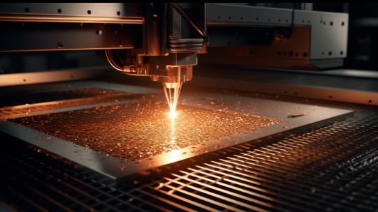
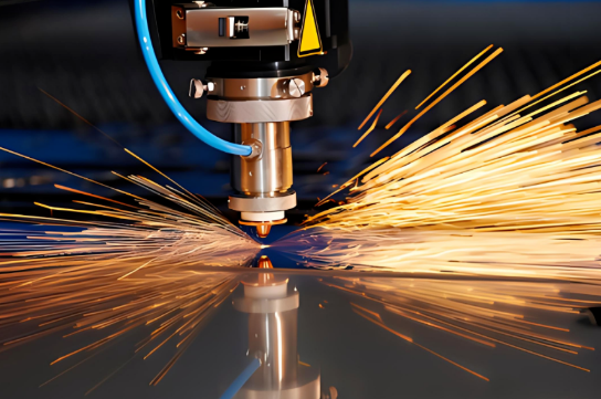
Voici comment la magie opère : un faisceau laser à haute puissance traverse des optiques spécialisées — miroirs ou lentilles — qui concentrent la lumière sur un point précis de la surface métallique. Lorsque cette énergie concentrée atteint la pièce, la température augmente instantanément de façon spectaculaire. Le métal au point focal fond, s’évapore ou s’enflamme, créant ainsi un chemin de coupe étroit appelé « kerf ».
Ce qui rend ce procédé remarquable pour la fabrication de l’acier et d’autres applications de transformation des métaux, c’est la faible quantité de déchets générée. Contrairement aux méthodes de découpe traditionnelles, qui éliminent une quantité importante de matériau, une machine à découper au laser produit des coupes aussi fines que quelques millièmes de pouce. Résultat ? Plus de matériau utilisable à partir de chaque tôle, ainsi que des bords plus nets, souvent exempts de toute finition secondaire.
Du faisceau focalisé à la pièce finie
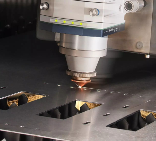
Le parcours allant du métal brut au composant fini implique plusieurs étapes coordonnées. Tout d’abord, les concepteurs créent des modèles numériques à l’aide de logiciels de CAO tels que Solidworks, en précisant exactement où doivent être effectués les découpes. Ces fichiers deviennent ensuite des instructions guidant la machine de découpe laser, lui indiquant avec précision où diriger son faisceau.
Pendant la découpe, des gaz auxiliaires — généralement de l’oxygène, de l’azote ou de l’air comprimé — évacuent le matériau fondu de la zone de coupe tout en influençant à la fois la qualité du bord et la vitesse de découpe. Cette combinaison d’énergie focalisée et d’assistance gazeuse permet à la découpe laser de traiter aussi bien des tôles d’aluminium délicates de 0,5 mm que des plaques d’acier robustes de 25 mm.
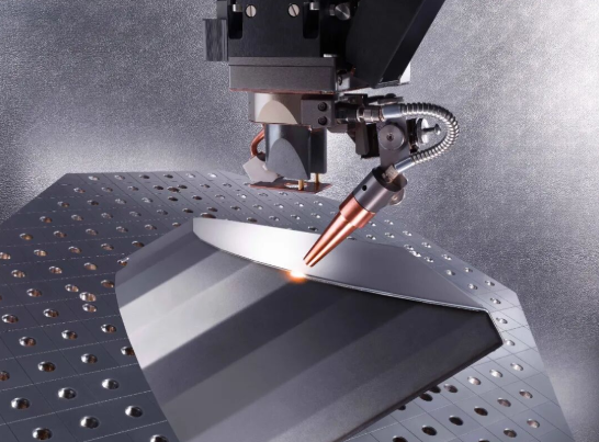
La fabrication moderne repose fortement sur cette technologie, et pour de bonnes raisons. Des composants de châssis automobiles nécessitant des tolérances serrées aux supports aérospatiaux exigeant une précision absolue, le découpage au laser offre une constance que les méthodes manuelles ne peuvent tout simplement pas égaler. Selon une analyse sectorielle, le marché des machines de découpe au laser a connu une croissance substantielle, reflétant son rôle essentiel dans de nombreux secteurs industriels.
Une machine de découpe au laser peut produire trois résultats principaux, selon les réglages de puissance et les besoins d’application :
- Coupe: La séparation complète du matériau, permettant de créer des pièces distinctes à partir de tôles métalliques
- Gravure : L’élimination de matière afin de créer de la profondeur et de la texture sans percer entièrement le matériau
- Marquage : Des modifications superficielles destinées à l’identification, au marquage ou à des fins décoratives
Que vous recherchiez des composants prototypes ou que vous planifiiez des séries de production de milliers de pièces, comprendre le fonctionnement de la découpe laser vous place dans une position plus forte pour évaluer les prestataires de services et prendre des décisions éclairées concernant vos projets de fabrication métallique. Ce guide vous accompagne pas à pas dans tous les aspects, du choix de la technologie à l’optimisation de la conception, afin que vos pièces soient conformes dès la première réalisation.
Technologies laser à fibre, au CO2 et au Nd:YAG expliquées
Vous savez donc comment fonctionne la découpe laser des métaux — mais quelle technologie laser doit réellement usiner vos pièces ? Cette question revêt une importance plus grande que vous ne le pensez. Le type de machine à découper au laser pour métaux que vous choisissez influence directement la qualité de coupe, la vitesse de traitement et les matériaux pouvant être traités efficacement. Examinons ensemble les trois technologies principales auxquelles vous serez confronté lors de la recherche de services de découpe laser à fibre ou de l’évaluation des capacités des équipements.
Lasers à fibre et leur domination dans le traitement des métaux minces
Si vous travaillez avec des métaux — en particulier des métaux réfléchissants comme l’aluminium et le cuivre — les lasers à fibre sont devenus la référence absolue. Ces systèmes à état solide génèrent leur faisceau au moyen de fibres optiques dopées avec des éléments de terres rares, tels que l’ytterbium, puis délivrent cette énergie directement au point de coupe.
Pourquoi les lasers à fibre sont-ils si efficaces pour la découpe laser de l’aluminium et d’autres métaux ? Cela tient à leur longueur d’onde. Fonctionnant à environ 1,06 micromètre dans le spectre proche infrarouge, les lasers à fibre produisent une lumière que les métaux absorbent facilement. Cela signifie moins d’énergie renvoyée vers la machine et davantage d’énergie consacrée à votre découpe.
Selon l’analyse technique de Xometry, les lasers à fibre offrent une qualité exceptionnelle du faisceau, avec une faible divergence et des diamètres de spot réduits. Cela se traduit par des découpes plus fines et plus précises, ainsi qu’une énergie spécifique plus élevée au point de coupe. Le résultat pratique ? Des vitesses de découpe plus rapides sur les matériaux minces, des bords plus nets et la capacité de traiter ces métaux réfléchissants « problématiques » qui posent des difficultés aux autres types de lasers.
Un autre avantage convaincant réside dans la simplicité de la maintenance. En l’absence de miroirs nécessitant un alignement et grâce à une construction quasi entièrement à l’état solide, les lasers à fibre peuvent fonctionner plusieurs dizaines de milliers d’heures avant de nécessiter une intervention importante. Dans les environnements de production à fort volume, cette fiabilité se traduit directement par une meilleure disponibilité et des coûts d’exploitation réduits.
Lorsque la technologie CO₂ reste pertinente
Bien que les lasers à fibre dominent les manchettes, la technologie au CO₂ reste pleinement pertinente — en particulier si votre activité s’étend au-delà de la simple découpe de métaux. Ces dispositifs à excitation gazeuse utilisent un mélange de dioxyde de carbone, d’azote et d’hélium pour générer leur faisceau, fonctionnant à une longueur d’onde plus longue d’environ 10,6 micromètres.
Cette longueur d’onde plus longue crée un compromis intéressant. Bien que les métaux réfléchissent plus facilement l’énergie des lasers au CO₂ (ce qui les rend moins efficaces pour la découpe pure de métaux), les matériaux organiques tels que le bois, l’acrylique, le cuir et les tissus l’absorbent exceptionnellement bien. Si votre atelier traite des pièces composées de matériaux variés ou si vous envisagez des outils laser pour la découpe de métaux capables également de traiter des matériaux non métalliques, les lasers au CO₂ offrent une polyvalence que les systèmes à fibre ne sauraient égaler.
Pour les applications métalliques, les lasers au CO2 conservent encore leur avantage lors de la découpe d’acier doux plus épais. Cette technologie bénéficie de décennies d’améliorations, et, grâce à des techniques appropriées de gaz auxiliaire, il est possible d’obtenir des découpes de haute qualité sur des tôles d’épaisseur importante. Le coût initial inférieur de l’équipement par rapport aux systèmes à fibre haute puissance rend également le laser au CO2 un point d’entrée attractif pour les ateliers souhaitant développer leurs capacités.
Le compromis ? Des exigences plus élevées en matière de maintenance. Comme Le guide de spécifications d'ADHMT le signale, les systèmes au CO2 comportent des miroirs et des composants optiques nécessitant un nettoyage régulier et un réalignement délicat. La source laser principale se dégrade également avec le temps, ce qui signifie que les performances diminuent progressivement dès le premier jour.
Lasers Nd:YAG pour des travaux de précision spécialisés
Moins fréquemment évoqués, mais néanmoins pertinents pour des applications spécifiques, les lasers Nd:YAG (grenat d’yttrium-aluminium dopé au néodyme) occupent une niche spécialisée. Ces dispositifs à état solide émettent à 1,064 micromètre — une longueur d’onde quasi identique à celle des lasers à fibre —, mais produisent leur faisceau au moyen d’un milieu amplificateur cristallin plutôt que fibre-optique.
Dans quels domaines les lasers Nd:YAG excellent-ils ? Pensez aux applications de précision nécessitant une forte puissance crête : soudage, gravure profonde et découpe de métaux épais, où des impulsions d’énergie fortement concentrées comptent davantage que la puissance continue. Les secteurs automobile, aérospatial et de la défense utilisent ces systèmes lorsque l’application exige des performances allant au-delà de celles offertes par la découpe laser standard de tôles.
La fabrication moderne s’est largement orientée vers la technologie à fibre pour les applications générales de découpe, car les lasers à fibre offrent des avantages similaires en termes de longueur d’onde tout en présentant des besoins d’entretien plus simples. Toutefois, les systèmes Nd:YAG conservent une valeur ajoutée pour les ateliers réalisant des travaux spécialisés qui requièrent leurs caractéristiques impulsionnelles uniques.
Comparaison des technologies : faire un choix éclairé
Comprendre ces différences vous aide à poser les bonnes questions lors de l’évaluation d’une machine de découpe laser pour tôle ou de la sélection d’un prestataire de services. Voici comment ces trois technologies se comparent selon les caractéristiques les plus importantes :
| Spécification | Laser à fibre | Laser CO2 | Laser Nd:YAG |
|---|---|---|---|
| Longueur d'onde | ~1,06 µm (proche infrarouge) | ~10,6 µm (loin infrarouge) | ~1,064 µm (proche infrarouge) |
| Meilleures applications métalliques | Acier inoxydable, acier au carbone, aluminium, cuivre, laiton, alliages réfléchissants | Acier doux épais ; mieux adapté aux ateliers traitant des métaux mixtes et/ou des non-métaux | Métaux épais, soudage de précision, applications de gravure profonde |
| Plage d'épaisseur typique | Jusqu’à 30 mm et plus (acier) avec des systèmes haute puissance ; excellente sur les épaisseurs fines à moyennes | Jusqu’à 25 mm d’acier ; efficace sur une large gamme d’épaisseurs | Varie selon l'application ; adapté aux matériaux plus épais nécessitant une puissance maximale |
| Efficacité énergétique | Élevé (> 30 % de conversion électro-optique) | Plus faible (consommation d'énergie plus élevée par watt de découpe) | Modéré |
| Exigences en matière d'entretien | Faible ; pas de miroirs, alignement minimal, durée de vie opérationnelle longue | Plus élevé ; nécessite un nettoyage optique régulier, un réalignement et un remplacement périodique de la source | Modéré ; construction robuste avec entretien périodique du cristal/de la pompe |
Lors de l’évaluation des services de découpe laser, cette connaissance technique vous transforme d’un acheteur passif en un partenaire informé. Vous pouvez poser des questions ciblées : « Quelle source laser utilisez-vous pour les pièces en aluminium ? » ou « Comment gérez-vous les défis liés aux matériaux réfléchissants ? ». Les prestataires qui répondent avec assurance et précision démontrent une expertise approfondie — exactement ce que vous recherchez lorsque la précision est primordiale.
Maintenant que vous connaissez la technologie laser adaptée à chaque type de matériau, explorons comment certains métaux réagissent concrètement au procédé de découpe — et quelle qualité de chantier vous pouvez raisonnablement attendre de chacun.
Guide de sélection des matériaux pour des résultats optimaux au laser
Vous maîtrisez déjà votre technologie laser — mais voici le point essentiel : même le laser à fibre le plus puissant ne sauvera pas un projet si vous avez choisi le mauvais matériau pour la tâche. Les différents métaux réagissent de façon radicalement différente lorsque le faisceau focalisé atteint leur surface. Comprendre ces comportements avant de soumettre votre commande peut faire la différence entre des pièces livrées prêtes à l’emploi et des pièces nécessitant des retouches coûteuses.
Pourquoi le choix du matériau est-il si déterminant ? Trois propriétés physiques régissent entièrement le processus : la réflectivité (proportion d’énergie laser renvoyée par rapport à celle qui est absorbée), la conductivité thermique (vitesse à laquelle la chaleur se dissipe hors de la zone de découpe) et le point de fusion (quantité d’énergie requise pour effectivement enlever le matériau). Une mauvaise compréhension de ces relations entraîne des découpes irrégulières, des dommages thermiques excessifs ou une qualité de bord qui ne répond tout simplement pas à vos spécifications.
Caractéristiques de performance de l’acier et de l’acier inoxydable
Si vous débutez dans la découpe au laser, commencez par l’acier doux. Ce matériau robuste est, comme Universal Tool le souligne , « relativement facile à couper avec n’importe quel laser destiné à la découpe des métaux ». Sa réflectivité modérée signifie que la majeure partie de l’énergie laser est directement concentrée sur la zone de coupe, tandis que ses propriétés thermiques permettent d’obtenir des bords propres et réguliers sur une large gamme d’épaisseurs.
Une tôle d’acier pouvant atteindre 25 mm d’épaisseur peut être traitée avec des résultats de haute qualité à l’aide de systèmes à fibre ou au CO₂ dotés d’une puissance adéquate. Les tôles plus fines sont découpées encore plus rapidement, ce qui fait de l’acier doux le choix privilégié lorsque l’efficacité économique prime sur la résistance à la corrosion.
La tôle d’acier inoxydable présente un défi légèrement différent. Bien qu’elle reste très compatible avec la découpe au laser, sa conductivité thermique plus faible concentre la chaleur de façon plus intense le long du trajet de coupe. Cela engendre des zones plus étendues affectées par la chaleur (ZAC) — c’est-à-dire des zones où la microstructure du métal est modifiée en raison de l’exposition thermique.
Pour les applications impliquant de l'acier inoxydable 316 ou d'autres nuances austénitiques, vous devrez discuter dès le départ avec votre prestataire des attentes concernant la zone affectée thermiquement (ZAT). Pour les applications critiques, un gaz d'assistance à base d'azote peut être requis afin de minimiser l'oxydation et d'obtenir des bords plus propres et plus brillants. La bonne nouvelle ? Comme l'indique Universal Tool, « il est relativement simple d'obtenir des bords propres et de haute qualité avec un laser à fibre, même sur des épaisseurs plus importantes. »
Gérer les défis posés par les métaux réfléchissants
À présent, les choses deviennent intéressantes. Les tôles en aluminium, le cuivre et le laiton posaient historiquement des problèmes pour la découpe au laser : leur forte réflectivité renvoyait l'énergie vers la source laser, risquant d'endommager l'équipement et de produire des découpes irrégulières.
Technologie Laser à Fibre a totalement changé la donne. Selon des experts du secteur, « avec les machines actuelles de découpe au laser à fibre, la réflectivité ne constitue plus un problème. » La longueur d'onde plus courte des lasers à fibre (environ 1,06 micromètre) est absorbée plus efficacement par ces métaux, permettant des découpes nettes que les anciens systèmes au CO₂ étaient tout simplement incapables d'assurer de façon fiable.
Cependant, l’aluminium présente un inconvénient : sa conductivité thermique. Comme l’explique Vytek, « des matériaux tels que l’aluminium, un métal très conducteur et à point de fusion bas, peuvent être particulièrement délicats à travailler. L’apport de chaleur doit être soigneusement maîtrisé afin d’obtenir un équilibre optimal entre vitesse de découpe et qualité du bord. » Les bords des tôles en aluminium présentent souvent un aspect légèrement différent de ceux des tôles en acier — généralement avec des stries plus marquées et un risque de légers bavures sur les surfaces de sortie.
Le cuivre et le laiton nécessitent des considérations similaires. Bien que les lasers à fibre gèrent efficacement leur réflectivité, la forte conductivité thermique de ces deux métaux exige des réglages de puissance plus élevés afin de compenser la dissipation thermique. Les épaisseurs fines sont découpées proprement ; en revanche, les sections plus épaisses peuvent présenter davantage de signes d’effets thermiques.
Capacités d’épaisseur par type de métal
Quelle épaisseur pouvez-vous réellement découper tout en conservant une qualité optimale des bords ? Ce tableau fournit des attentes réalistes, fondées sur les systèmes industriels typiques à laser à fibre :
| Type de métal | Épaisseur maximale typique (bord de qualité) | Qualité prévue des bords | Considérations particulières |
|---|---|---|---|
| Acier doux | Jusqu'à 25 mm | Lisse, sans oxyde avec assistance azote ; une légère oxydation est acceptable avec assistance oxygène | Matériau le plus tolérant ; excellent pour les débutants |
| Tôle en acier inoxydable | Jusqu'à 20mm | Bords propres et brillants possibles ; certaines décolorations peuvent apparaître à des épaisseurs supérieures | Assistance azote recommandée pour les applications sensibles à la corrosion |
| Feuille d'aluminium | Jusqu'à 15 mm | Striations visibles ; de petits bavures sont possibles sur le côté de sortie | Laser à fibre requis ; réglages haute puissance pour les sections plus épaisses |
| Cuivre | Jusqu'à 10 mm | Bonne qualité des bords ; effets thermiques peuvent apparaître sur les découpes plus épaisses | Laser à fibre haute puissance indispensable ; vitesses de découpe plus lentes |
| Laiton | Jusqu'à 10 mm | Découpes propres avec des réglages appropriés ; risque d’une légère oxydation | Laser à fibre privilégié ; manipulation similaire à celle du cuivre |
Point clé : La tôle métallique que vous choisissez influence directement à la fois les résultats réalisables et ce à quoi ressemble la « qualité » de vos pièces finies. Établissez des attentes réalistes en fonction des propriétés du matériau, et non uniquement des capacités du laser.
Ce à quoi vous pouvez vous attendre à la réception des pièces
Voici une recommandation souvent négligée : la qualité des bords varie selon le matériau, et l’idée de « perfection » diffère d’un type de métal à l’autre.
Pour les applications de découpe laser de tôles en acier inoxydable et en acier doux, attendez-vous à des bords lisses nécessitant peu ou pas d’opérations de finition secondaires. Des couches d’oxyde peuvent être présentes si un gaz auxiliaire d’oxygène a été utilisé — ceci est normal et n’a généralement pas d’incidence sur la fonctionnalité, sauf si la propreté de surface est critique.
Les pièces en aluminium arrivent souvent avec une texture de bord légèrement plus rugueuse. Ces stries visibles sont caractéristiques du procédé, et non des défauts. Si votre application exige des bords plus lisses, veuillez préciser cette exigence dès la phase initiale — cela pourrait nécessiter des vitesses de découpe plus lentes ou des opérations secondaires.
Les métaux spéciaux tels que le cuivre et le laiton peuvent présenter une certaine décoloration près des bords découpés en raison de l'exposition à la chaleur. Pour les applications décoratives, discutez des options de finition avec votre prestataire avant le début de la production.
Maintenant que vous comprenez comment les différents matériaux réagissent à la découpe laser, l'étape suivante consiste à vous assurer que vos fichiers de conception sont correctement préparés — car même un choix parfait de matériau ne sauvera pas un projet dont les fichiers CAO sont défectueux.
Préparation des fichiers de conception pour obtenir des pièces conformes dès la première fois
Vous avez sélectionné le matériau approprié — vient maintenant l'étape où de nombreux projets dérapent : la préparation des fichiers. Votre fichier de conception constitue essentiellement le manuel d'instructions qui indique précisément à la machine laser où effectuer la découpe. Une erreur à ce stade entraîne le rejet des fichiers, des retards de production ou des pièces non conformes aux spécifications. En revanche, une préparation rigoureuse garantit que vos pièces découpées au laser arrivent exactement telles que prévues.
Voici la réalité : les machines à découper au laser n’interprètent pas les images de la même manière que vos yeux. Ce magnifique rendu PNG de votre support ? Inutilisable. La machine a besoin de tracés mathématiques précis — des vecteurs — qui définissent exactement le parcours du faisceau. Comprendre cette différence fondamentale permet de distinguer les projets couronnés de succès des répétitions frustrantes.
Éléments essentiels des fichiers vectoriels pour éviter les retards de production
Lors de la préparation des fichiers destinés à la découpe laser de tôles métalliques, le format prime sur l’esthétique. Selon les recommandations techniques de conception de Quote Cut Ship, « les machines à découper au laser n’interprètent pas les fichiers JPEG ou PNG comme le fait votre logiciel de conception. Pour des découpes propres et précises, vous devez utiliser un format basé sur les vecteurs. »
Les formats de fichiers acceptés pour les opérations de découpe métallique sur mesure comprennent :
- DXF (Drawing Interchange Format) : La norme du secteur. Comme l’explique Xometry, le DXF est « un type de fichier vectoriel pouvant être utilisé par différents logiciels de CAO, ce qui permet de créer un fichier dans un logiciel puis de l’ouvrir dans un autre ». Son caractère open source garantit sa compatibilité avec pratiquement tous les systèmes de découpe laser.
- DWG : Format natif d’AutoCAD, offrant des fonctionnalités similaires à celles du DXF, avec une préservation supplémentaire de certaines données.
- AI (Adobe Illustrator) : Excellente pour les conceptions créées dans des logiciels de graphisme, à condition que tous les éléments soient correctement vectorisés.
- SVG (Scalable Vector Graphics) : Format convivial pour le web, qui se prête bien aux applications de découpe.
Quelle particularité distingue les fichiers vectoriels ? Ils définissent des tracés au moyen de coordonnées mathématiques plutôt que de grilles de pixels. Lorsqu’une machine de découpe laser lit votre fichier DXF, elle identifie précisément les points de départ, les points d’arrivée et les courbes, qui se traduisent directement en mouvements du faisceau. Les images matricielles (JPEG, PNG, BMP) ne contiennent que des informations de couleur relatives aux pixels : la machine ignore totalement où effectuer la découpe.
Comprendre le kerf : la largeur que votre conception doit prendre en compte
Voici un concept qui peut déstabiliser même les designers expérimentés : le kerf (ou largeur de coupe). Lorsqu’un faisceau laser découpe du métal, il ne crée pas une ligne d’épaisseur infiniment fine : il enlève du matériau. Cette largeur de matériau retiré correspond au kerf ; ignorer ce paramètre conduit à des pièces légèrement sous-dimensionnées ou à des éléments qui ne s’assemblent pas comme prévu.
La largeur de kerf varie selon plusieurs facteurs : le type de laser, l’épaisseur du matériau, la vitesse de découpe et la pression du gaz auxiliaire. Pour des pièces découpées au laser sur des tôles minces, on observe généralement des valeurs de kerf comprises entre 0,1 mm et 0,3 mm. Les matériaux plus épais produisent en général un kerf plus large.
Faut-il compenser le kerf dans vos fichiers de conception ? Cela dépend entièrement de votre prestataire de services. Remarques de SendCutSend que leurs « services propriétaires de découpe laser et de découpe par jet d’eau compensent automatiquement la largeur du faisceau et le kerf dans votre fichier de pièce, de sorte que si vous appliquez cette compensation vous-même avant de nous l’envoyer, la pièce obtenue risque de sortir des tolérances spécifiées. »
Vérifiez toujours auprès de votre prestataire : applique-t-il automatiquement la compensation de la largeur de coupe (kerf), ou devez-vous l’intégrer vous-même dans votre conception ? Une erreur à ce niveau double votre erreur de tolérance.
Erreurs de conception courantes qui augmentent vos coûts
Après avoir examiné des centaines de fichiers soumis, les prestataires signalent systématiquement les mêmes erreurs évitables. Éviter ces erreurs dans vos projets de découpe sur mesure de tôles permet de gagner du temps, de l’argent et d’éviter des frustrations :
- Espacement insuffisant entre les découpes : Lorsque les lignes de conception sont trop rapprochées, le laser peut provoquer une surchauffe des zones adjacentes ou affaiblir l’intégrité structurelle. Les recommandations industrielles préconisent un espacement d’au moins 0,010 pouce (0,25 mm) entre les trajectoires de coupe critiques. Pour les matériaux plus épais, cet espacement doit être augmenté de façon proportionnelle.
- Éléments trop petits par rapport à l’épaisseur du matériau : Ce motif complexe est magnifique à l’écran, mais le laser peut-il réellement l’exécuter physiquement ? La géométrie interne minimale ne doit jamais être inférieure à 0,015 pouce, et les trous ou découpes doivent généralement mesurer au moins 50 % de l’épaisseur de votre matériau. Une plaque de 3 mm d’épaisseur ne doit pas comporter de trous de 1 mm de diamètre.
- Coins internes trop vifs provoquant des concentrations de contraintes : Des coins internes parfaitement droits à 90 degrés sont structurellement faibles et difficiles à réaliser proprement au laser. Ajoutez de petits rayons de congé (même de 0,5 mm) aux coins internes afin d’améliorer à la fois la fabricabilité et la résistance de la pièce.
- Spécifications de tolérances manquantes : Si votre pièce exige une précision dimensionnelle spécifique, communiquez-la clairement. La découpe laser standard garantit une précision d’environ ±0,005 pouce sur les matériaux minces, mais les dimensions critiques doivent être explicitement indiquées.
- Tracés ouverts ou non joints : Les lacunes dans vos tracés vectoriels perturbent le logiciel de découpe. Comme l’indique l’outil Quote Cut Ship, « des tracés non joints ou ouverts peuvent perturber la machine à découper au laser, notamment lors des opérations de gravure ou d’entaille. » Utilisez les outils de nettoyage des tracés fournis par votre logiciel pour vous assurer que toutes les formes sont correctement fermées.
- Texte non converti en courbes : Les polices de caractères dépendent du logiciel utilisé. Si votre prestataire ne dispose pas de la police exacte que vous avez employée, le texte peut se décaler ou disparaître entièrement. Convertissez tout le texte en tracés ou en contours avant l’exportation — cela transforme les lettres en géométrie pure, interprétable par n’importe quel système.
Tailles minimales des éléments selon l'épaisseur du matériau
Quelle est la taille minimale possible ? Cette relation entre l’épaisseur du matériau et les détails réalisables est essentielle pour les pièces complexes découpées au laser :
| Épaisseur du matériau | Diamètre minimal du trou | Largeur minimale de la fente | Largeur minimale de pont (entre deux découpes) |
|---|---|---|---|
| 0,5 mm – 1,0 mm | 0,5 mm | 0,5 mm | 0,5 mm |
| 1,0 mm - 3,0 mm | 1,0 mm (ou 50 % de l’épaisseur) | 1,0 mm | 1,0 mm |
| 3,0 mm – 6,0 mm | 1,5 mm – 3,0 mm | 1,5 mm | 1,5 mm - 2,0 mm |
| 6,0 mm et plus | Égale ou supérieure à l’épaisseur | 2,0 mm+ | 2,0 mm+ |
Liste de vérification pour la préparation des fichiers avant soumission
Avant de téléverser votre conception pour la production de pièces découpées au laser, suivez ces étapes de vérification :
- Le fichier est au format vectoriel (DXF, DWG, AI ou SVG)
- Tous les objets se trouvent sur une seule couche (sauf indication contraire du prestataire)
- Les lignes en double et les points isolés ont été supprimés
- Tous les tracés sont fermés et correctement joints
- Le texte a été converti en contours/tracés
- La conception est à l’échelle 1:1, avec les unités correctes spécifiées
- Les dimensions minimales des éléments respectent les exigences liées à l’épaisseur du matériau
- Les angles intérieurs présentent des rayons appropriés
- L'espacement entre les découpes répond aux exigences minimales
- L'approche de compensation de la largeur de coupe est confirmée avec le prestataire
Prendre ces étapes de préparation au sérieux transforme votre relation avec les services de découpe laser, passant d'une résolution réactive des problèmes à une précision proactive. Vos fichiers deviennent prêts à la production dès leur première soumission — pas d'échanges répétés, pas de frais imprévus liés à la correction des fichiers.
Une fois vos fichiers de conception correctement préparés, la question suivante devient stratégique : la découpe laser est-elle réellement la technologie adaptée à votre projet spécifique, ou des méthodes alternatives telles que la découpe par jet d’eau ou la découpe plasma permettraient-elles d’obtenir de meilleurs résultats ?
Comparaison entre la découpe laser, la découpe par jet d’eau, la découpe plasma et l’usinage CNC
Vos fichiers de conception sont prêts, votre matériau est sélectionné — mais voici une question à se poser avant de vous engager : un laser capable de découper des métaux est-il réellement le meilleur choix pour votre projet spécifique ? Parfois, c’est absolument le cas. D’autres fois, la découpe par jet d’eau, la découpe plasma, l’usinage CNC ou l’électroérosion permettent d’obtenir de meilleurs résultats à moindre coût. Prendre une mauvaise décision à ce stade signifie payer pour des capacités dont vous n’avez pas besoin — ou, pire encore, recevoir des pièces qui ne répondent pas aux spécifications.
Examinons objectivement chaque technologie de découpe de métaux afin que vous puissiez associer le procédé adapté à vos besoins réels, plutôt que de choisir par défaut celui qui vous est le plus familier.
Cadre décisionnel pour choisir votre méthode de découpe
Cinq grands services de découpe de métaux se font concurrence pour vos projets. Chacun excelle dans des scénarios précis et présente des limites dans d’autres. Comprendre ces compromis vous transforme d’un acheteur passif en une personne capable de définir avec précision les exigences de son projet.
Découpe laser : rapidité et précision pour les matériaux minces à moyens
Lors de la découpe au laser de l'acier ou d'autres métaux, vous exploitez une énergie thermique concentrée pour obtenir des découpes exceptionnellement rapides et précises. Selon La comparaison technique de Flow Waterjet , « La découpe au laser est une méthode efficace si vous devez réaliser le travail rapidement. Elle est également relativement précise. »
Cette technologie donne les meilleurs résultats sur des matériaux d'épaisseur faible à moyenne, où la vitesse est un facteur déterminant. Des géométries complexes comportant des courbes serrées et des détails intriqués ? Le laser les traite sans effort. Les coûts de configuration restent minimes, car il n'y a aucun outillage physique à remplacer entre deux opérations : il suffit de télécharger un nouveau fichier et de commencer la découpe.
Toutefois, cette méthode présente certaines limites. L'épaisseur maximale traitable est généralement de l'ordre de 25 mm pour l'acier, avec des bords de bonne qualité, et les métaux fortement réfléchissants posaient traditionnellement des problèmes (bien que les lasers à fibre modernes aient largement résolu ce point). Le procédé thermique génère également des zones affectées par la chaleur, ce qui peut revêtir une importance particulière dans les applications métallurgiquement sensibles.
Découpe à jet d'eau : une découpe à froid sans compromis thermique
Imaginez couper du métal à l’aide d’eau sous pression de 60 000 psi mélangée à des particules abrasives de grenat. C’est ce qu’on appelle la découpe par jet d’eau — et son avantage déterminant est l’absence totale d’apport thermique. Comme le confirment les analyses sectorielles, la découpe par jet d’eau « ne génère aucune contrainte ni aucune marque induite par la chaleur sur votre produit fini. »
Ce procédé de découpe à froid permet de traiter pratiquement n’importe quel matériau jusqu’à une épaisseur de 24 pouces pour des découpes grossières — bien au-delà des performances atteintes par les procédés laser de découpe de métaux. La même machine qui découpe des composants aéronautiques en titane peut également tailler du verre, de la pierre ou des composites, sans nécessiter de modification de l’équipement.
Le compromis ? La vitesse. Le jet d’eau est plus lent que le laser sur les matériaux minces, et la consommation d’abrasif entraîne des coûts d’exploitation récurrents. Pour les travaux de grande série sur tôle mince, ce procédé perd souvent la comparaison économique.
Découpe plasma : un procédé économique pour le traitement des métaux épais
La découpe au plasma utilise un gaz surchauffé et ionisé pour percer des métaux conducteurs — et ce, à moindre coût. Selon la comparaison de Flow, « parmi les quatre méthodes de découpe, le plasma est la moins coûteuse ».
Pour les services de découpe d’acier impliquant des tôles épaisses où la qualité du bord n’est pas critique, la découpe au plasma s’impose. Elle permet de traiter des matériaux plus épais que le laser et coûte moins cher par découpe que la découpe à l’eau sous haute pression. Ce procédé est largement utilisé dans la construction, la fabrication d’équipements lourds et la fabrication d’éléments en acier structurel.
Les inconvénients sont toutefois importants pour les travaux de précision : largeur de la fente (kerf) plus importante, bords plus rugueux nécessitant une finition secondaire, et zones affectées thermiquement plus étendues que celles produites par le laser. La découpe au plasma génère également des résidus (laitance ou bavures) qui doivent souvent être éliminés par meulage. Si vos pièces exigent des tolérances serrées ou des bords impeccables, tournez-vous vers une autre méthode.
Usinage CNC : précision soustractive pour des géométries 3D complexes
Contrairement aux procédés de découpe thermique, l’usinage CNC retire le matériau par contact physique avec des outils de coupe rotatifs. Cette approche fondamentalement différente excelle là où les autres rencontrent des difficultés : caractéristiques tridimensionnelles, taraudages, poches précises et surfaces à tolérances serrées.
Envisagez l’usinage CNC comme un procédé complémentaire plutôt que concurrentiel. Alors que le laser découpe des profils 2D dans des tôles, le CNC usine des pièces 3D à partir de blocs pleins. De nombreux projets nécessitent en réalité les deux procédés : des ébauches découpées au laser suivies d’un usinage CNC pour les caractéristiques impossibles à réaliser au laser.
Les coûts évoluent également différemment. L’usinage CNC implique une usure des outils, des temps de cycle plus longs et une fixation plus complexe. Pour des profils 2D simples, il est presque toujours plus coûteux que le laser. Pour des pièces 3D complexes, il constitue souvent la seule option viable.
Usinage par électro-érosion à fil : précision ultime pour les applications exigeantes
L'usinage par électro-érosion à fil occupe une niche spécialisée. En utilisant un fil électriquement chargé immergé dans un fluide diélectrique, l’électro-érosion permet d’atteindre des tolérances si fines que les autres procédés paraissent grossiers — nous parlons ici de ±0,0001 pouce dans des conditions idéales.
Selon l’analyse technique de Zintilon, l’électro-érosion à fil « excelle dans la réalisation de découpes précises et exactes, éliminant ainsi le besoin de traitements ou d’opérations de finition supplémentaires sur la pièce usinée. » Elle permet de travailler des matériaux trempés qui détruirait des outils de coupe conventionnels et produit des bords exempts de bavures, sans déformation thermique.
L’inconvénient ? La vitesse. L’électro-érosion est généralement le procédé le plus lent parmi tous ceux évoqués ici. Elle est également limitée aux matériaux électriquement conducteurs. Pour des volumes de production importants ou des profils simples, les coûts liés à l’électro-érosion deviennent prohibitifs. Toutefois, pour la fabrication de matrices et de moules, de composants aérospatiaux exigeant une précision extrême, ou de formes complexes dans des aciers trempés, aucun autre procédé ne lui est comparable.
Où la découpe laser est moins performante que les alternatives
La découpe au laser est exceptionnelle, mais pas universelle. Voici les cas où vous devriez envisager des alternatives :
- Matériaux d’une épaisseur supérieure à 25 mm : Le jet d’eau ou le plasma traitent plus efficacement les tôles épaisses
- Applications sensibles à la chaleur : La découpe à jet d’eau, qui ne génère pas de chaleur, élimine totalement les problèmes thermiques
- Exigences de précision extrême : L’usinage par électro-érosion filaire atteint des tolérances que la découpe au laser ne peut pas égaler
- caractéristiques tridimensionnelles requises : L’usinage CNC ajoute des fonctionnalités que la découpe au laser ne propose tout simplement pas
- Travaux sur acier épais avec contraintes budgétaires : Le plasma coûte nettement moins cher pour les applications nécessitant des tolérances approximatives
- Matériaux non conducteurs : Le jet d’eau permet de découper du verre, de la pierre et des composites que le laser ne peut pas traiter
Comparaison complète des technologies
Ce tableau complet résume les performances de chaque technologie de découpe d'acier selon les spécifications les plus importantes pour votre prise de décision :
| Spécification | Découpe laser | Découpe au jet d'eau | Les produits | Usinage CNC | EDM à fil |
|---|---|---|---|---|---|
| Plage de tolérance typique | ±0,005 po (matériaux minces) | ±0,003" à ±0,005" | ±0,5 à ±0,76 mm | ±0,001" à ±0,005" | ±0,0001" à ±0,001" |
| Capacité d’épaisseur de matériau | Jusqu'à 25 mm (acier) | Jusqu'à 24" (découpe brute) | Jusqu'à 50 mm+ | Limité par l'enveloppe de la machine | Jusqu'à 12" |
| Zone affectée par la chaleur | Présent (minimal avec des paramètres appropriés) | Aucun (découpage à froid) | Significatif | Le minimum | Le minimum |
| Qualité de la finition du bord | Excellent sur les matériaux minces ; bon sur les matériaux épais | Finition satinée lisse ; aucune finition secondaire nécessaire | Rugueux ; nécessite souvent un meulage | Excellent ; surface usinée | Excellent ; sans bavure |
| Coûts relatifs de configuration | Faibles (basés sur des fichiers) | Faible à modéré | Faibles | Modérés à élevés (fixation) | Modéré (installation de câbles) |
| Meilleurs cas d'utilisation | Tôles minces à moyennes ; profils 2D complexes ; production en grande série | Matériaux épais ; travaux sensibles à la chaleur ; ateliers multi-matériaux | Acier épais ; travaux structurels axés sur le budget | pièces 3D ; éléments filetés ; surfaces à tolérances serrées | Précision extrême ; matériaux trempés ; géométries complexes |
Prendre sa décision technologique
Posez-vous ces questions lors du choix de votre approche en matière de services de découpe de métaux :
- Quel est le type et l’épaisseur de votre matériau ?
- Quelles tolérances votre application exige-t-elle réellement ?
- Vos pièces peuvent-elles tolérer des zones affectées par la chaleur ?
- Avez-vous besoin de profils 2D ou de caractéristiques 3D ?
- Quel volume produisez-vous ?
- Quelle est votre priorité budgétaire : la rapidité, la précision ou le coût par pièce ?
Pour la plupart des applications en tôle d’épaisseur inférieure à 20 mm, nécessitant une bonne précision et un délai d’exécution rapide, le découpage au laser reste le choix optimal. Toutefois, savoir quand des alternatives sont plus pertinentes — et être en mesure d’expliquer précisément pourquoi — renforce votre position lors des négociations et garantit que vous sélectionnez le procédé adapté à vos besoins spécifiques.
Une fois que vous avez confirmé que le découpage au laser correspond aux exigences de votre projet, la prochaine étape cruciale consiste à bien comprendre les niveaux de précision et les normes de qualité auxquels vous pouvez vous attendre pour vos pièces finies.
Tolérances de précision et normes de qualité auxquelles vous devez vous attendre
Vous avez choisi la découpe au laser, préparé correctement vos fichiers et sélectionné le matériau approprié. Mais c’est ici que de nombreux acheteurs sont pris au dépourvu : ils n’ont aucune idée de ce à quoi ressemble concrètement une « qualité » satisfaisante lorsque les pièces arrivent. Quelles tolérances pouvez-vous réellement attendre ? Comment évaluer si les bords répondent aux spécifications ? Et lorsqu’une pièce semble défectueuse, s’agit-il réellement d’un défaut ou simplement d’une variation normale ?
Comprendre ces critères de qualité avant l’expédition de vos pièces vous transforme d’un simple destinataire passif en un inspecteur averti. Vous saurez exactement ce que vous devez accepter, ce que vous devez remettre en question et ce que vous devez rejeter sans appel.
Comprendre les classes de tolérance pour différentes applications
La tolérance — l’écart autorisé par rapport à une dimension spécifiée — varie considérablement en fonction de l’épaisseur du matériau, du type de métal et de la qualité de l’équipement. Selon la documentation technique d’ADHMT, « Les machines de découpe laser haut de gamme peuvent maintenir des tolérances aussi serrées que ±0,1 mm, selon des facteurs tels que le type de matériau, son épaisseur et les paramètres de la machine. »
Pour les matériaux minces de moins de 3 mm, on peut s’attendre à des tolérances standard d’environ ±0,005 pouce (soit environ ±0,127 mm). Ce niveau de précision convient à la plupart des applications de fabrication de tôles sans problème. Toutefois, à mesure que l’épaisseur du matériau augmente, l’obtention de ces mêmes tolérances serrées devient exponentiellement plus difficile.
Pourquoi l'épaisseur est-elle si déterminante ? La physique est simple : des matériaux plus épais nécessitent davantage d'énergie, des vitesses de coupe plus lentes et des temps d'exposition plus longs. Cette entrée de chaleur prolongée élargit la zone affectée thermiquement, augmente le risque de déformation thermique et rend plus difficile le maintien d'une largeur de coupe constante. Le profil conique intrinsèque du faisceau laser provoque également un léger biseautage : la largeur de la découpe en haut peut légèrement différer de celle en bas.
| Épaisseur du matériau | Tolérance typique réalisable | Notes d'application |
|---|---|---|
| Sous 3 mm | ±0,005 po (±0,127 mm) | Pièces de précision, boîtiers électroniques, supports détaillés |
| 3 mm - 6 mm | ±0,008 po à ±0,010 po (±0,2 mm à ±0,25 mm) | Fabrication générale, composants structurels |
| 6mm - 12mm | ±0,010 po à ±0,015 po (±0,25 mm à ±0,38 mm) | Supports robustes, pièces de machines |
| Au-delà de 12 mm | ±0,015 po à ±0,020 po (±0,38 mm à ±0,5 mm) | Plaques structurelles, équipements industriels |
Lors de l'examen d'un tableau des épaisseurs de tôle pour choisir l'épaisseur de votre matériau, n'oubliez pas que les valeurs de jauge influencent directement la précision réalisable. Des jauges plus fines permettent systématiquement d'obtenir des tolérances plus serrées : si votre application exige une extrême précision, concevoir avec une tôle plus fine est souvent plus judicieux que de lutter contre les lois de la physique sur des tôles épaisses.
Critères d'inspection qualité que vous devriez exiger
La précision dimensionnelle ne constitue qu’un élément du puzzle qualité. La fabrication professionnelle de tôles en acier inoxydable et les tôles métalliques découpées au laser de précision doivent satisfaire plusieurs critères d’inspection qui, pris dans leur ensemble, définissent ce qu’est une « qualité acceptable ».
Selon Guide de contrôle qualité d'IvyCNC , quatre facteurs clés déterminent la qualité de la découpe : la rugosité de surface, la régularité de la largeur de la fente de coupe (kerf), la perpendicularité et les caractéristiques de la zone affectée thermiquement. Examinons précisément ce à quoi vous devez prêter attention.
Surface roughness
Passez votre doigt le long du bord découpé. Les découpes laser de qualité sont relativement lisses — pas polies miroir, mais dépourvues de crêtes ou de stries excessives. Les normes industrielles mesurent la rugosité de surface en valeurs Ra (rugosité moyenne), les bonnes découpes laser atteignant généralement une valeur Ra de 12,5 à 25 micromètres sur l’acier. La présence de lignes de traînée visibles est normale ; en revanche, des entailles profondes ou des stries marquées indiquent un problème de paramétrage.
Perpendicularité du bord
Placez votre pièce contre une équerre de mécanicien. Le bord découpé doit être perpendiculaire aux surfaces supérieure et inférieure dans les tolérances spécifiées — typiquement de 1 à 3 degrés pour un travail standard, avec des tolérances plus serrées pour les applications de précision. Une conicité excessive suggère un positionnement incorrect du point focal ou un défaut d’alignement du faisceau.
Présence de bavures
Les bavures—ces arêtes vives et saillantes formées lorsque le matériau fondu se resolidifie—constituent un problème courant de qualité. Une faible présence de bavures est acceptable pour de nombreuses applications, mais des bavures importantes indiquent des paramètres incorrects, des consommables usés ou une pression inadéquate du gaz auxiliaire. Les pièces destinées à être manipulées en toute sécurité ou nécessitant un ajustement précis doivent parvenir pratiquement dépourvues de bavures.
Zone affectée par la chaleur
La décoloration adjacente aux bords découpés indique une exposition thermique. Une certaine variation de couleur est normale, notamment sur l’acier inoxydable. Toutefois, une largeur excessive de la zone affectée thermiquement (ZAT) ou une décoloration sévère suggèrent un apport de chaleur trop important, pouvant ainsi altérer les propriétés du matériau dans cette zone. Pour les applications critiques, spécifiez un gaz auxiliaire azote afin de minimiser l’oxydation et l’étendue de la ZAT.
Formation de bavures
Qu'est-ce que la bavure ? Pour la définir précisément : il s'agit du métal en fusion qui se resolide et adhère au bord inférieur des découpes, formant des dépôts rugueux et globuleux. Selon le guide de dépannage de LYAH Machining, la bavure résulte généralement d'« une vitesse de découpe, une puissance ou une pression de gaz auxiliaire incorrectes ». Des découpes de qualité doivent présenter une bavure minimale, voire nulle ; des dépôts importants nécessitent un dégrossissage et révèlent des problèmes liés au procédé.
Votre liste de contrôle qualité pour l'évaluation des pièces reçues
Utilisez cette liste de contrôle lors de l'inspection de tôles métalliques découpées au laser provenant de tout fournisseur :
- Précision dimensionnelle : Mesurez les dimensions critiques à l'aide d'un pied à coulisse. Sont-elles conformes aux tolérances spécifiées ?
- Lissage du bord : Passez un doigt le long des bords découpés. Vérifiez la présence d'une rugosité excessive, de stries profondes ou de sections irrégulières.
- Perpendicularité : Vérifiez l'orthogonalité des bords découpés à l'aide d'une équerre. Recherchez une inclinaison excessive ou un écart angulaire important.
- Évaluation des bavures : Inspectez soigneusement les bords inférieurs. De légères bavures peuvent être acceptables ; en revanche, des bavures importantes nécessitant un retrait sont problématiques.
- Présence de bavure : Examiner la face inférieure des découpes. Des bords de sortie propres indiquent des paramètres corrects ; une forte formation de laitance suggère des problèmes liés au procédé.
- Discoloration due à la chaleur : Remarquer toute décoloration excessive. Une teinte bleutée ou brunâtre sur l’acier inoxydable est normale ; un noircissement par carbonisation ne l’est pas.
- Déformation ou gauchissement : Placer les pièces sur une surface plane. Vérifier la présence d’un bombage, d’une torsion ou d’une déformation thermique, en particulier sur les pièces minces ou allongées.
- Intégrité des caractéristiques : Vérifier que les petits trous, les fentes et les éléments complexes sont entièrement découpés, sans percement partiel ni endommagement excessif des bords.
- Cohérence entre les pièces : Si vous avez commandé plusieurs exemplaires, comparez plusieurs pièces. La qualité doit être uniforme sur l’ensemble de la série.
Certifications sectorielles attestant de l’engagement qualité
Les certifications constituent une validation externe du fait que les systèmes de gestion de la qualité d’un fournisseur répondent à des normes reconnues. Deux certifications revêtent une importance particulière dans le domaine de la fabrication de tôlerie :
ISO 9001 : La norme fondamentale de gestion de la qualité applicable à tous les secteurs industriels. La certification ISO 9001 atteste de l’existence de procédures documentées, d’audits réguliers et d’approches systématiques en matière de maîtrise de la qualité. Pour la fabrication à usage général, cette certification offre une confiance raisonnable quant à la constance des processus.
IATF 16949 : La norme qualité spécifique au secteur automobile, nettement plus exigeante que l’ISO 9001. Selon des sources du secteur, « les tolérances dans le domaine automobile sont strictement contrôlées afin de garantir un ajustement précis des pièces au sein d’assemblages complexes, contribuant ainsi aux performances globales et à la sécurité du véhicule. » Si vos pièces sont destinées à des applications automobiles — ou à tout autre assemblage critique pour la sécurité — la certification IATF 16949 indique qu’un fournisseur est capable de répondre à des exigences rigoureuses.
Résolution des problèmes courants de qualité
Lorsque des pièces arrivent avec des problèmes, identifier les causes profondes vous permet de communiquer efficacement avec votre fournisseur et d’éviter leur récurrence.
Formation excessive de scories
Causes : vitesse de coupe trop lente, pression du gaz auxiliaire trop faible, mauvais alignement de la buse ou gaz auxiliaire contaminé. Solution : demander un ajustement des paramètres et une inspection de la buse. Les pièces présentant des bavures importantes indiquent généralement que le fournisseur doit recalibrer ses paramètres pour votre matériau spécifique.
Décoloration des bords
Causes : apport de chaleur excessif, gaz auxiliaire à base d’oxygène (qui provoque intentionnellement une oxydation) ou environnement de découpe contaminé. Pour les aciers inoxydables nécessitant des bords propres, spécifiez un gaz auxiliaire à base d’azote. Remarques d’usinage LYAH qu’une sélection appropriée du gaz auxiliaire « produit des bords brillants, exempts d’oxydes et de bavures, prêts à être soudés directement. »
Déformation due aux contraintes thermiques
Causes : Le chauffage et le refroidissement rapides génèrent des contraintes internes. Les matériaux minces et les pièces allongées sont particulièrement vulnérables. Selon les recommandations techniques, une gestion efficace de la déformation thermique implique « la réduction de l’apport thermique total grâce à des vitesses de découpe plus élevées, à la découpe par impulsions ou à des séquences de découpe optimisées ». Si la déformation persiste, discutez avec votre fournisseur des solutions de serrage ou de stratégies alternatives de découpe.
Qualité de découpe incohérente
Causes : Consommables usés (buse, lentille), dérive du point focal, hétérogénéité du matériau ou facteurs environnementaux tels que les fluctuations de température. Les experts en contrôle qualité soulignent que « bon nombre de ces défauts proviennent tout simplement d’un désaccord entre les capacités de la machine et le matériau à découper ». Demandez la documentation relative au calendrier d’entretien du fournisseur ainsi qu’aux procédures de vérification des matériaux.
Conseil professionnel : En cas de problèmes de qualité sur votre première commande, demandez des pièces échantillons avant de vous engager sur des volumes de production pour les projets futurs. Un fournisseur réactif accueillera volontiers cette demande — il est bien moins coûteux d’identifier les problèmes tôt que de retoucher des lots entiers.
Fort(e) d’attentes claires en matière de qualité et de critères d’inspection définis, vous êtes désormais en mesure d’évaluer les pièces de façon objective. La considération suivante devient tout aussi pratique : comprendre comment les coûts évoluent en fonction du volume et quels facteurs influencent le plus significativement votre résultat net.
Facteurs de coût et économies d’échelle liées au volume pour une commande intelligente
Vous avez parfaitement défini la conception, choisi le matériau adapté et validé vos attentes en matière de qualité. Il ne reste plus qu’à répondre à la question qui déterminera, en fin de compte, si votre projet avance : quel sera réellement son coût ? Comprendre l’économie des services de découpe laser — notamment la manière dont les prix évoluent en fonction des quantités — vous aide à prendre des décisions plus éclairées concernant le moment opportun pour réaliser un prototype, celui où vous devez passer à la production en série, et les domaines sur lesquels concentrer vos efforts d’optimisation des coûts.
Voici ce que de nombreux acheteurs négligent : les tarifs de la découpe laser ne sont pas linéaires. Le coût unitaire pour dix pièces diffère considérablement de celui pour mille pièces. Maîtriser cette relation vous permet de structurer vos commandes de façon stratégique, plutôt que de simplement accepter la première offre reçue.
Économie du prototype contre tarification en fonction du volume de production
Lorsque vous commandez un seul prototype ou un petit nombre de pièces, vous payez bien plus que le coût des matériaux et du temps de découpe. Selon l’analyse des coûts de Thinklaser, la préparation initiale et la programmation nécessaires aux conceptions sur mesure augmentent sensiblement le coût total — en particulier pour les projets unitaires.
Quels facteurs font-ils augmenter le coût des prototypes ? Plusieurs éléments s’ajoutent les uns aux autres :
- Répartition du temps de mise en service : La préparation de la machine, le traitement des fichiers et la mise en place des matériaux prennent à peu près le même temps, que vous découpiez une seule pièce ou cinquante. Répartir ce coût fixe sur une seule pièce le rend donc très élevé.
- Inefficacité liée aux matériaux : Une seule petite pièce découpée sur une grande tôle entraîne un gaspillage important de matériau. Vous achetez en effet la tôle entière, même si vous n’avez besoin que d’une petite portion.
- Frais de manutention : Chaque commande exige des étapes chronophages qui ne varient pas proportionnellement à la quantité : établissement d’un devis, planification, inspection qualité et coordination de l’expédition.
Comme l’explique la comparaison des coûts du fournisseur, la découpe au laser convient bien pour des quantités allant jusqu’à environ 1 000 à 3 000 pièces, avant que d’autres procédés, tels que l’emboutissage, ne deviennent plus économiques — bien que ce seuil varie considérablement en fonction de la taille et de la complexité de la pièce.
Les volumes de production inversent cette équation. Lorsque vous commandez des centaines ou des milliers de pièces, ces coûts fixes de mise en route sont répartis sur l’ensemble de la série. Les logiciels de nesting optimisent l’utilisation des matériaux, permettant de placer le plus grand nombre possible de pièces par plaque. Les opérateurs acquièrent un rythme de travail qui réduit le temps de manipulation par pièce. Résultat ? Le coût unitaire peut diminuer de 40 à 70 % par rapport aux prix appliqués aux prototypes.
Vérification rapide de la réalité : si un prototype coûte 50 $ par pièce, ne partez pas du principe que le prix de fabrication en série sera de 50 $ multiplié par la quantité. Demandez des devis pour plusieurs paliers de quantité — vous découvrirez souvent des seuils optimaux où des économies substantielles entrent en jeu.
Coûts cachés qui affectent votre résultat net
Le prix de découpe cité ne raconte que rarement l’histoire complète. Plusieurs facteurs peuvent faire gonfler votre facture finale bien au-delà de vos attentes initiales.
Type et épaisseur du matériau
Les différents métaux ont des coûts distincts, tant pour la matière première que pour le temps de découpe. L’acier inoxydable coûte plus cher que l’acier doux. L’aluminium nécessite davantage d’énergie par pouce. Des épaisseurs supérieures ralentissent considérablement les vitesses de découpe, augmentant ainsi le temps machine et, par conséquent, le coût. Selon les recommandations sectorielles en matière de tarification, la découpe de métaux plus épais et plus denses augmente proportionnellement à la fois le temps requis et les frais associés.
Complexité du design
Les designs complexes comportant des courbes, de petits détails et des motifs élaborés prennent plus de temps à découper que de simples rectangles. Comme le souligne Laserfab, « plus les lignes de votre conception sont longues, plus leur réalisation prend du temps, ce qui augmente le coût ». Chaque courbe, chaque angle, chaque opération de perçage ajoute du temps machine.
Exigences de tolérance
Les tolérances standard sont proposées aux prix standard. Lorsque vous spécifiez des tolérances plus serrées, les prestataires peuvent être amenés à réduire les vitesses de découpe, à effectuer des contrôles qualité supplémentaires ou à utiliser des équipements haut de gamme, ce qui augmente les coûts.
Opérations secondaires
Les pièces sont rarement expédiées directement depuis la table de découpe laser. Les opérations secondaires telles que le pliage, la mise en forme, l’insertion de composants, le soudage et les finitions ajoutent chacune une couche de coûts. Si vos pièces nécessitent un traitement de revêtement poudre ou d’autres traitements de surface, intégrez ces postes dans votre budget total dès le départ. Sur des ensembles complexes, les coûts de finition peuvent parfois dépasser ceux de la découpe.
Lorsque vous recherchez des ateliers de fabrication à proximité, interrogez-les spécifiquement sur leurs capacités en opérations secondaires. Les ateliers proposant des services intégrés offrent souvent une meilleure valeur globale que la répartition du travail entre plusieurs fournisseurs, car cela élimine les frais d’expédition et les retards de coordination entre la découpe et la finition.
Délai de réalisation
Les commandes express entraînent des tarifs majorés. Selon une analyse du secteur, la découpe laser peut démarrer dans les 24 à 72 heures pour les projets urgents — mais cette rapidité a un coût. Les délais de production standard de 5 à 10 jours offrent généralement des prix plus avantageux. Planifiez à l’avance lorsque cela est possible.
Stratégies d’optimisation des coûts qui fonctionnent
Les acheteurs avisés ne se contentent pas d’accepter les devis — ils optimisent activement leurs projets pour améliorer leur rentabilité. Ces stratégies permettent systématiquement de réduire les coûts sans compromettre la qualité :
- Imbrication efficace : Collaborez avec votre prestataire sur l’orientation et le regroupement des pièces. Selon des experts en fabrication, « le nesting réorganise les pièces à découper afin qu’elles partagent des bords communs et génèrent le moins d’espace excédentaire possible ». Des formes complémentaires qui s’emboîtent comme des pièces de puzzle minimisent les déchets et réduisent les coûts des matériaux.
- Standardiser les épaisseurs de matériau : Utilisez des épaisseurs standard que vos prestataires stockent régulièrement afin d’éviter les majorations liées aux commandes spéciales et les retards de livraison. Si une épaisseur de 14 convient presque aussi bien qu’une épaisseur de 13, l’option standard permet de réaliser des économies.
- Concevez vos pièces pour limiter au maximum les opérations secondaires : Chaque courbe, chaque soudure ou chaque étape de revêtement par poudre augmente les coûts. Réfléchissez à la possibilité de repenser les pièces afin d’éliminer les opérations postérieures — ou du moins d’en réduire la complexité.
- Regrouper les pièces similaires : Regrouper plusieurs références dans une seule commande améliore l’efficacité de la disposition (nesting) et réduit les frais de mise en place. Si vous avez besoin de plusieurs composants différents, mais tous dans la même épaisseur de matériau, commandez-les ensemble.
- Simplifiez les trajectoires de découpe : Comme le conseille Laserfab, supprimer les lignes de découpe double et toute complexité superflue réduit directement le temps de découpe. Examinez vos fichiers à la recherche de trajectoires superposées ou de détails inutiles pouvant être supprimés.
- Prenez en compte les seuils de quantité : Commander légèrement plus que votre besoin immédiat est souvent pertinent lorsque des remises pour volumes s’appliquent. Les économies unitaires obtenues au seuil de quantité suivant peuvent justifier le maintien d’un petit stock.
Équilibrer la validation des prototypes et l’économie de production
Voici la question stratégique : à quel moment faut-il commander des prototypes, et à quel moment passer directement à la production ?
Pour les nouveaux designs, la fabrication de prototypes rapporte presque toujours. Une petite série d’essai — même à un prix unitaire majoré — coûte beaucoup moins cher que la découverte de problèmes sur une commande de production de 500 pièces. Les recommandations du secteur confirment que la construction de la confiance grâce à des essais préliminaires « renforce la confiance dans le résultat et réduit les coûts liés à la résolution des anomalies détectées en amont. »
Toutefois, pour des designs éprouvés ou des géométries simples, la fabrication de prototypes peut constituer une dépense inutile. Si vous découpez des supports basiques dans un matériau bien maîtrisé et avec des tolérances non critiques, passer directement à des quantités de production est souvent pertinent.
L’approche hybride convient bien à de nombreux acheteurs : commander une petite série de validation au début d’un nouveau projet, puis passer à des séries de production plus importantes une fois que le design est figé. Cette stratégie équilibre la gestion des risques et l’efficacité coût.
En ayant une compréhension claire des facteurs de coût et des stratégies d’optimisation, la dernière pièce du puzzle consiste à choisir le prestataire adapté pour exécuter votre projet — une décision qui influe non seulement sur le prix, mais aussi sur la qualité, la communication et le potentiel de partenariat à long terme.
Comment évaluer et sélectionner le bon partenaire en découpe laser
Vous maîtrisez la technologie, vous avez optimisé vos fichiers de conception et vous connaissez précisément les normes de qualité attendues. Il ne vous reste plus qu’à prendre, sans doute, la décision la plus déterminante de l’ensemble de votre projet : choisir qui réalisera effectivement la découpe de vos pièces. La différence entre un prestataire excellent de services de découpe laser sur métaux et un prestataire médiocre ne réside pas uniquement dans le prix — elle tient au fait que vos pièces arrivent dans les délais, répondent aux spécifications requises et s’intègrent sans accroc dans votre assemblage, sans mauvaises surprises coûteuses.
Considérez la sélection d’un fournisseur comme une diligence raisonnable qui porte ses fruits à chaque commande future. Prenez le temps, dès le départ, d’évaluer soigneusement ses capacités, et vous éviterez les tracas liés à la découverte de problèmes une fois la production lancée.
Des questions qui révèlent les véritables capacités d’un fournisseur
N’importe qui peut affirmer sur son site web disposer de qualité et d’expertise. Les bonnes questions permettent de distinguer les capacités réelles du simple langage marketing. Selon Le guide d’évaluation des fournisseurs de Wrightform , poser des questions ciblées « permet d’économiser du temps et de l’argent tout en évitant des erreurs coûteuses. »
Lors de l’évaluation de prestataires de découpe laser situés à proximité ou à distance, ces questions révèlent ce qui compte le plus :
- Quels matériaux pouvez-vous traiter, et quelles épaisseurs êtes-vous en mesure de découper ? Tous les ateliers ne sont pas équipés de la même manière. Vérifiez qu’ils travaillent bien avec le type précis de métal et l’épaisseur (calibre) que vous utilisez. Les lasers à fibre haute puissance traitent mieux les métaux réfléchissants et les matériaux plus épais que les anciens systèmes au CO₂ — le bon équipement pour votre matériau est donc essentiel.
- Quel niveau de précision pouvez-vous atteindre ? Demandez des plages de tolérance précises pour l’épaisseur de votre matériau. Des réponses floues telles que « très précise » signalent d’éventuels problèmes. Les prestataires de qualité indiquent des valeurs numériques concrètes, par exemple ±0,005 po pour les matériaux minces.
- Proposez-vous des services de prototypage ? Comme le confirme la réglementation sectorielle, « la fabrication de prototypes vous permet de valider une conception avant de passer à la production à grande échelle. » Les prestataires proposant un prototypage rapide démontrent leur souplesse et leur capacité à valider les conceptions.
- Comment optimisez-vous l’utilisation des matériaux afin de réduire les déchets ? Les prestataires disposant de logiciels avancés de découpe assistée par ordinateur (CAO/FAO) optimisent le rendement par plaque, ce qui réduit directement vos coûts de matériaux. Interrogez-les sur leur méthode de découpe optimisée (nesting) : cela révèle à la fois leur niveau de sophistication technique et leur souci de maîtrise des coûts.
- Quels formats de fichiers acceptez-vous, et pouvez-vous assister dans les modifications de conception ? Les formats standard incluent DXF et DWG. Plus important encore, sont-ils en mesure d’analyser vos fichiers afin d’y détecter d’éventuels problèmes de fabricabilité avant le début de la découpe ?
- Quel est votre délai d’exécution habituel, et proposez-vous des options accélérées ? Renseignez-vous sur les délais de livraison standards ainsi que sur les possibilités d’accélération. Certains prestataires expédient dans les 24 à 48 heures pour les travaux urgents — une option utile lorsque les plannings glissent.
- Proposez-vous des services complémentaires tels que la finition, l’assemblage ou l’emballage ? Les fabricants d'acier proposant des opérations secondaires intégrées permettent de gagner du temps en coordination et de réduire les coûts d'expédition par rapport à la répartition du travail entre plusieurs fournisseurs.
- Comment assurez-vous le contrôle qualité ? Renseignez-vous sur les procédures d'inspection, les équipements de mesure et la documentation. Que se passe-t-il lorsque les pièces ne respectent pas les spécifications ?
- Quelle expérience possédez-vous dans mon secteur d'activité ou sur des projets similaires ? Un fournisseur familier des tolérances automobiles fonctionne différemment d’un fournisseur destiné aux applications architecturales. Une expérience sectorielle permet d’anticiper vos besoins.
- Proposez-vous des tailles de commande flexibles ? Que vous ayez besoin de prototypes unitaires ou de séries de production comptant des milliers de pièces, des fournisseurs fiables s’adaptent à vos exigences réelles, sans imposer de quantités minimales inadaptées à votre projet.
L’avantage de l’analyse de la fabrication (DFM) : détecter les problèmes avant qu’ils ne coûtent cher
Le soutien à la conception pour la fabrication (DFM) distingue les simples exécutants de commandes des véritables partenaires industriels. Selon l’analyse de Dalsin Industries, la DFM « consiste à concevoir ou à ingénier un produit de manière à faciliter au mieux le processus de fabrication », avec pour avantages « une réduction des coûts ainsi qu’une détection et une résolution précoces des problèmes dès la phase de conception — ce qui constitue le stade le moins coûteux pour traiter les difficultés. »
À quoi ressemble concrètement un soutien DFM pertinent ? Un prestataire compétent examine vos fichiers avant le début de la production afin d’identifier d’éventuels problèmes : des caractéristiques trop petites par rapport à l’épaisseur de votre matériau, des espacements risquant de provoquer un surbrûlage, des angles vifs générant des concentrations de contraintes ou des tolérances spécifiées dépassant les capacités réalistes. Il propose des modifications améliorant la fabricabilité sans compromettre la fonctionnalité.
Pour les applications automobiles et de précision, cette approche proactive devient essentielle. La certification IATF 16949 — la norme rigoureuse en matière de qualité du secteur automobile — indique des prestataires capables de fournir la documentation, le contrôle des processus et l’amélioration continue exigés par des applications exigeantes. Des fabricants tels que Shaoyi Metal Technology illustrent cette norme grâce à un soutien complet en ingénierie concourante (DFM), à la réalisation de prototypes en 5 jours et à un délai de réponse aux devis de 12 heures, ce qui comble efficacement l’écart entre la conception et la production.
Signaux d’alarme lors de l’évaluation des services de découpe mécanique
Aussi important que ce qu’il faut rechercher est la capacité à identifier les signaux d’alarme révélateurs de problèmes potentiels. Selon les recommandations d’évaluation des fournisseurs d’EWM, les évaluateurs doivent « noter précisément les signaux d’alarme et obtenir des réponses à ces préoccupations. Ne pas poursuivre l’évaluation de ce fournisseur tant que ces questions n’ont pas reçu de réponse. »
Soyez vigilant face aux signaux d’alarme suivants lors de votre recherche de services de découpe laser métallique à proximité ou de l’évaluation de prestataires éloignés :
- Des réponses vagues ou évasives concernant les équipements : Une réticence à discuter des types spécifiques de lasers, des niveaux de puissance ou des marques de machines suggère soit un équipement obsolète, soit un manque de connaissances techniques.
- Absence de certifications qualité : Bien que tous les travaux ne nécessitent pas la certification ISO 9001 ou IATF 16949, les prestataires ne disposant d’aucun système de management de la qualité risquent de ne pas appliquer de processus cohérents.
- Communication floue concernant les délais de livraison : S’ils ne peuvent pas fournir des échéanciers réalistes lors de la phase de devis, préparez-vous à des imprévus chronologiques pendant la production.
- Absence de revue DFM (Design for Manufacturability) proposée : Les prestataires qui se contentent de découper tout fichier que vous leur envoyez — sans fournir aucun retour sur l’aptitude à la fabrication — risquent de ne détecter les problèmes qu’au moment où les pièces échouent aux contrôles d’inspection.
- Réticence à fournir des échantillons : Les prestataires exigeants accueillent favorablement les demandes d’échantillons. Une résistance à usiner des pièces-tests avant de s’engager sur des volumes de production soulève des interrogations.
- Réactivité médiocre en matière de communication : Avec quelle rapidité répondent-ils aux demandes d’information ? Le délai de réponse durant la phase de devis est généralement révélateur de la qualité de la communication pendant la production.
- Absence de documentation relative à l’entretien ou à l’étalonnage : L'équipement entretenu selon le calendrier prévu produit des résultats constants. Les prestataires incapables de discuter de leurs pratiques d'entretien peuvent connaître des dérives affectant la qualité.
Évaluation des pièces échantillons avant l'engagement en production
Ne vous engagez jamais dans des volumes de production importants avec un prestataire non éprouvé. La demande de pièces échantillons — même au prix des prototypes — permet de valider les capacités avant un investissement significatif.
Lors de l'évaluation des échantillons provenant d'un service de découpe laser sur mesure, appliquez la liste de contrôle qualité de la section précédente : précision dimensionnelle, finition des bords, perpendicularité, présence de bavures et cohérence entre plusieurs pièces. Évaluez également des facteurs moins tangibles :
- Ont-ils respecté le délai annoncé ? La performance en matière de livraison des échantillons préfigure la fiabilité en production.
- Comment ont-ils géré vos questions ou demandes de modifications ? La qualité de la communication lors d'une petite commande est révélatrice de ce que vous expérimenterez sur des projets plus importants.
- La documentation était-elle complète ? Les pièces sont-elles parvenues accompagnées de rapports d'inspection, de certificats de matériaux ou d'autres documents requis ?
- Quelle était la qualité de l'emballage ? Les pièces endommagées pendant le transport reflètent négativement l’attention portée aux détails dans son ensemble.
Selon les meilleures pratiques en matière d’évaluation des fournisseurs, les fournisseurs existants doivent être « régulièrement requalifiés ». Même après avoir établi une relation de travail, des évaluations périodiques sur échantillons permettent de s’assurer que la qualité ne s’est pas dégradée au fil du temps.
Construire votre cadre d’évaluation des prestataires
Élaborez une approche systématique pour comparer les fabricants de métaux situés à proximité ou à distance. Attribuez une note à chaque prestataire selon des critères cohérents :
| Critères d'évaluation | Poids (1-5) | Note du prestataire A | Note du prestataire B |
|---|---|---|---|
| Capacité des équipements à traiter vos matériaux | 5 | — | — |
| Capacité de tolérance documentée | 4 | — | — |
| Certifications qualité (ISO, IATF) | 4 | — | — |
| Assistance DFM fournie | 5 | — | — |
| Réactivité en matière de communication | 4 | — | — |
| Compétitivité des délais de livraison | 3 | — | — |
| Capacités d'opérations secondaires | 3 | — | — |
| Qualité des pièces échantillons | 5 | — | — |
| Concurrence sur les prix | 3 | — | — |
| Expérience dans des secteurs spécifiques | 3 | — | — |
Critères pondérés en fonction de vos priorités spécifiques : pour les applications critiques en matière de qualité, les certifications et la qualité des échantillons peuvent être davantage valorisées, tandis que, pour les projets sensibles au coût, l’accent peut être mis sur le prix et les délais de livraison. Cette comparaison structurée évite de prendre des décisions fondées uniquement sur le devis le moins élevé.
N’oubliez pas : le fournisseur le moins cher n’est souvent pas le choix le plus économique une fois pris en compte le coût des retouches, des retards et des problèmes de qualité. Investissez du temps dès la phase d’évaluation pour identifier des partenaires capables de délivrer de la valeur tout au long du cycle de vie complet du projet.
Votre cadre d’évaluation des fournisseurs étant désormais établi, vous êtes prêt à passer de la recherche à l’action. La dernière étape consiste à traduire l’ensemble des enseignements tirés dans un plan d’exécution pratique, permettant de faire passer votre projet de la conception initiale aux pièces finies entre vos mains.
Votre plan d’action pour des pièces métalliques découpées au laser réussies
Vous avez assimilé une quantité considérable d’informations — allant des types de technologies laser et des comportements des matériaux aux normes de préparation des fichiers et aux critères d’évaluation des prestataires. Il est maintenant temps de transformer ces connaissances en action. Cette section finale condense l’ensemble en une feuille de route pratique que vous pouvez suivre, depuis votre premier croquis de conception jusqu’à la réception, dans vos locaux, des pièces métalliques découpées au laser.
Considérez ceci comme un résumé exécutif et un guide d’exécution combinés. Que vous fabriquiez un prototype d’un seul support ou que vous lanciez une série de production de milliers de pièces, ces étapes vous permettent de parcourir le processus efficacement et d’éviter les erreurs coûteuses qui compromettent les acheteurs moins bien préparés.
Votre liste de vérification pré-commande pour les pièces découpées au laser
Avant de soumettre toute commande, passez en revue cette liste de vérification. Chaque point aborde une décision traitée dans ce guide — omettre l’un d’eux risque de provoquer des problèmes ultérieurement.
| Catégorie | Point de contrôle | Vérifié ? |
|---|---|---|
| Choix des Matériaux | Le type de matériau correspond aux exigences de l’application (résistance à la corrosion, résistance mécanique, poids) | ☐ |
| L'épaisseur est adaptée aux besoins structurels et aux tolérances réalisables | ☐ | |
| Les attentes en matière de qualité des bords sont conformes aux propriétés du matériau | ☐ | |
| Optimisation de la conception | Les dimensions minimales des éléments respectent les exigences liées à l’épaisseur du matériau | ☐ |
| Les angles internes présentent des rayons appropriés (et non des angles droits aigus) | ☐ | |
| L'espacement entre les découpes dépasse les exigences minimales | ☐ | |
| Préparation des fichiers | Le fichier est au format vectoriel (DXF, DWG, AI ou SVG) | ☐ |
| Tous les tracés sont fermés et correctement joints | ☐ | |
| Le texte a été converti en contours/chemins | ☐ | |
| L'approche de compensation de la largeur de coupe (kerf) a été confirmée avec le prestataire | ☐ | |
| Spécification des tolérances | Les cotes critiques sont clairement indiquées sur les plans | ☐ |
| Les exigences en matière de tolérance sont réalisables compte tenu de l'épaisseur du matériau | ☐ | |
| Évaluation du prestataire | Capacité de l'équipement vérifiée pour votre type de matériau | ☐ |
| Certifications qualité adaptées à votre application | ☐ | |
| Examen DFM proposé avant la production | ☐ | |
| Pièces échantillons évaluées (pour les nouveaux fournisseurs) | ☐ |
Passer du concept de conception à la réalité de la production
Prêt à passer à l'exécution ? Suivez cette séquence numérotée, de la conception initiale jusqu'à la livraison finale. Chaque étape s'appuie sur la précédente, créant ainsi un parcours systématique qui réduit les risques et optimise l'efficacité.
- Définir les exigences de l'application : Avant d'utiliser un logiciel de CAO, documentez les fonctions que vos pièces doivent remplir. Quelles charges devront-elles supporter ? Dans quel environnement fonctionneront-elles ? Avec quels ensembles doivent-elles s'intégrer ? Ces réponses orientent toutes les décisions ultérieures.
- Sélectionner le matériau en fonction des besoins de performance : Adaptez les propriétés des matériaux à vos besoins : acier doux pour une résistance économique, acier inoxydable pour sa résistance à la corrosion, aluminium pour la réduction du poids. Prenez en compte la façon dont chaque métal réagit au découpage laser — réflectivité, conductivité thermique et qualité des bords obtenus.
- Concevez en pensant à la fabrication : Appliquez dès le départ les règles géométriques relatives au découpage laser des tôles métalliques. Prévoyez des rayons appropriés, respectez les dimensions minimales des éléments en fonction de l’épaisseur et assurez un espacement suffisant entre les découpes. Concevoir correctement dès le départ ne coûte rien ; reprendre la conception après des découpes infructueuses coûte tout.
- Préparez des fichiers prêts pour la production : Exportez des fichiers vectoriels propres aux formats acceptés. Vérifiez que tous les tracés sont fermés, supprimez les lignes en double et convertissez le texte en contours. Assurez-vous que les unités et l’échelle sont correctes. La qualité de ce fichier détermine directement si votre première soumission aboutit ou nécessite des itérations de révision.
- Spécifiez les tolérances et les exigences de qualité : Document indiquant les dimensions critiques et les tolérances requises. Préciser toute finition spéciale des bords, tout traitement de surface ou toute exigence d’inspection. Des spécifications claires évitent les litiges concernant ce qui constitue une qualité acceptable.
- Demandez des devis auprès de fournisseurs qualifiés : Soumettez vos fichiers et spécifications aux fournisseurs ayant satisfait à vos critères d’évaluation. Pour les projets de découpe sur mesure de métaux, demandez des devis à plusieurs niveaux de quantité afin de comprendre la rentabilité liée au volume. Vous devriez recevoir des devis détaillés dans les 24 à 48 heures auprès des fournisseurs réactifs.
- Procédez à un examen DFM avant la production : Cette étape distingue les projets réussis des projets problématiques. Selon meilleures pratiques de l'industrie , le contrôle qualité « commence avant tout début de découpe », grâce à des examens formels de conception portant sur les tolérances, le choix des matériaux et les jeux de fabrication. Un examen DFM approfondi permet de détecter les problèmes à un stade où leur correction est peu coûteuse — et non après que le matériau a été découpé.
- Commandez des prototypes pour validation (le cas échéant) : Pour les nouveaux designs ou les applications critiques, la validation de prototype est essentielle. Comme l’explique JC Proto, un simple essai « coûte bien moins cher que de découvrir des problèmes dans une commande de production de 500 pièces. » La réalisation de prototypes vous permet de vérifier l’ajustement, le fonctionnement et la qualité avant d’engager des ressources importantes.
- Approuver et lancer la production : Une fois que les prototypes ont validé votre conception, lancez la production en quantités définies. Confirmez les délais de livraison, les modalités d’expédition ainsi que toute opération secondaire requise. Une communication claire à ce stade évite les mauvaises surprises lors de la livraison.
- Inspecter les pièces reçues conformément aux spécifications : Lorsque les pièces arrivent, appliquez systématiquement votre liste de contrôle qualité. Vérifiez la précision dimensionnelle, la qualité des bords et l’intégrité des caractéristiques. Documentez immédiatement toute non-conformité — la plupart des fournisseurs traitent rapidement les problèmes de qualité lorsqu’ils sont signalés sans délai.
Pourquoi la consultation DFM est-elle essentielle pour les applications critiques ?
Pour les applications exigeantes — composants de châssis automobile, supports de suspension, ensembles structurels où la précision a un impact direct sur la sécurité et les performances — la consultation DFM n’est pas facultative. Il s’agit d’une gestion essentielle des risques.
Selon analyse d’ingénierie de fabrication , la DFM apporte des avantages mesurables : « une réduction des coûts ainsi qu’une détection et une résolution précoces des problèmes dès la phase de conception — ce qui constitue l’étape la moins coûteuse pour traiter les défis. » Le coût d’un examen préalable à la production est négligeable comparé à l’abandon d’une série de production ou, pire encore, aux défaillances sur le terrain dues à des défauts de fabrication.
Les fabricants certifiés IATF 16949 apportent une valeur particulière aux applications automobiles. Cette certification rigoureuse atteste de procédures documentées, de la maîtrise statistique des procédés et de systèmes d’amélioration continue que les fabricants généraux ne possèdent pas nécessairement. Lorsque vos pièces alimentent des ensembles critiques pour la sécurité, ce niveau de garantie qualité offre l’assurance que les spécifications seront systématiquement respectées, lot après lot.
Accélérez votre parcours vers des pièces prêtes à la production
Pour les lecteurs prêts à passer à la phase de réalisation de pièces métalliques de précision, le bon partenaire de fabrication accélère considérablement l’itération allant du concept à des composants prêts à la production. Les fabricants proposant la prototypage rapide avec un délai de réponse pour les devis extrêmement court — certains atteignant même 12 heures — vous permettent de valider vos conceptions et de figer les spécifications avant même que vos concurrents n’aient reçu leur premier devis.
Technologie métallique de Shaoyi (Ningbo) illustre cette approche accélérée, offrant une prototypage rapide en 5 jours ainsi que des capacités de production de masse certifiées IATF 16949 pour les châssis, les systèmes de suspension et les composants structurels. Leur soutien complet en ingénierie pour la fabrication (DFM) détecte les problèmes de fabricabilité avant qu’ils ne deviennent des difficultés coûteuses, tandis que les systèmes de production automatisés garantissent une constance, du prototype aux séries à haut volume.
Que vous validiez un nouveau concept de conception ou que vous passiez à l’échelle des pièces éprouvées pour la production en série, les principes décrits dans ce guide s’appliquent. Sélectionnez les matériaux avec soin. Concevez dès le départ pour la fabrication. Préparez vos fichiers correctement. Spécifiez clairement vos exigences. Choisissez vos partenaires avec rigueur. Et profitez d’un accompagnement en ingénierie pour la fabrication (DFM) afin de détecter les problèmes au stade où leur correction reste peu coûteuse.
Vos pièces ne sont pas meilleures que le procédé qui les fabrique. Investissez dès le départ l’effort nécessaire pour bien définir ce procédé, et vos pièces métalliques découpées au laser arriveront exactement telles que prévues — dans les délais, conformément aux spécifications et prêtes à fonctionner.
Questions fréquemment posées sur la découpe au laser de pièces métalliques
1. Quels matériaux ne peuvent pas être découpés au laser ?
Les machines de découpe au laser ne peuvent pas traiter en toute sécurité certains matériaux, notamment le PVC, le polycarbonate, le Lexan et certains plastiques qui dégagent des fumées toxiques lorsqu’ils sont chauffés. En ce qui concerne les métaux, les lasers CO₂ traditionnels rencontrent des difficultés avec des matériaux fortement réfléchissants comme le cuivre et le laiton, bien que les lasers à fibre modernes aient largement surmonté ces limitations. Vérifiez toujours la compatibilité des matériaux avec votre prestataire avant de soumettre vos commandes afin d’éviter tout dommage matériel ou tout risque pour la sécurité.
2. Quel est le coût de la découpe laser de métaux ?
La découpe laser des métaux coûte généralement entre 13 $ et 20 $ par heure de temps machine, bien que le prix par pièce varie considérablement en fonction du type de matériau, de son épaisseur, de la complexité de la conception et de la quantité commandée. Un seul prototype peut coûter 50 $ par pièce, tandis que des volumes de production atteignant plusieurs centaines d’unités peuvent réduire les coûts unitaires de 40 à 70 % grâce à l’amortissement des frais de mise en place et à une meilleure efficacité de placement (nesting). Les opérations secondaires, telles que le pliage ou la peinture poudre, entraînent des coûts supplémentaires. Demandez des devis pour plusieurs paliers de quantité afin de bien comprendre la rentabilité liée au volume pour votre projet spécifique.
3. Quel format de fichier est le mieux adapté pour la découpe laser de pièces métalliques ?
DXF (Drawing Interchange Format) est la norme industrielle pour la découpe au laser, car il est compatible avec pratiquement tous les logiciels de CAO et systèmes de découpe. Les autres formats acceptés incluent DWG, AI et SVG. L’exigence essentielle est que les fichiers doivent être vectoriels, et non des images matricielles telles que les JPEG ou les PNG. Les fichiers vectoriels définissent des tracés mathématiques précis qui se traduisent directement en mouvements du faisceau, garantissant ainsi des découpes précises. Convertissez toujours le texte en contours et vérifiez que tous les tracés sont correctement fermés avant soumission.
4. Quelles tolérances la découpe au laser peut-elle atteindre sur les pièces métalliques ?
La découpe laser de haute qualité permet d'atteindre des tolérances aussi serrées que ±0,005 pouce (±0,127 mm) sur des matériaux minces de moins de 3 mm. La capacité en tolérance diminue à mesure que l'épaisseur du matériau augmente, en raison d'une exposition thermique prolongée et des caractéristiques du faisceau. Pour les matériaux de 6 mm et plus, prévoyez des tolérances comprises entre ±0,010" et ±0,020". Les cotes critiques nécessitant une précision accrue doivent être clairement indiquées sur les plans, et des fabricants certifiés IATF 16949, tels que Shaoyi Metal Technology, proposent des processus qualité rigoureux pour les applications automobiles exigeantes et les applications de précision.
5. Quand dois-je choisir la découpe laser plutôt que la découpe par jet d’eau ou par plasma ?
Choisissez la découpe au laser pour les matériaux de faible à moyenne épaisseur (aciers de moins de 25 mm) nécessitant une grande précision, des géométries complexes et des délais de livraison courts. Le laser se distingue particulièrement pour les détails complexes et les tolérances serrées, à des coûts compétitifs. Optez pour la découpe par jet d’eau dans les applications sensibles à la chaleur, pour les matériaux très épais (jusqu’à 60 cm) ou pour les matériaux non conducteurs tels que le verre et les composites. La découpe plasma convient aux travaux sur acier épais lorsque le budget est contraint et que la qualité du bord n’est pas critique. Pour des besoins extrêmes en précision (±0,0001 po), l’électro-érosion filaire surpasse toutes les autres techniques, malgré des vitesses plus lentes.