 Pienet erät, korkeat standardit. Nopea prototyypinkehityspalvelumme tekee vahvistamisen nopeammaksi ja helpommaksi —

Lohkaisuprosessit selvitetty: Raakametallista valmiiksi osiksi
Mitä metallin syvämuovaus todella tarkoittaa nykyaikaisessa valmistuksessa
No mitä syvämuovaus sitten tarkoittaa? Ydinajatuksena metallin syvämuovaus on kylmämuovausvalmistusprosessi joka muuntaa litteää levymetallia tarkasti muotoiltuihin komponentteihin käyttäen erikoismuotteja ja korkeapainepressuja. Toisin kuin valaminen tai kuumamuovaus, tämä metalliprosessi perustuu mekaaniseen voimaan raaka-aineiden muovaamiseksi valmiiksi osiksi sulattamisen sijaan.
Metallin syvämuovaus on kylmämuovaus teollinen prosessi, jossa käytetään tarkkuusmuotteja ja korkeapainepressejä muovaamaan levymetalli valmiiksi komponenteiksi leikkamalla, taivuttamalla ja muovaamalla.
Syvämuovauksen merkityksen ymmärtäminen valmistuksessa auttaa arvostamaan, miksi tätä prosessia käytetään laajalti aloilla, jotka vaihtelevat autoteollisuudesta elektroniikkaan. Aina kun käännät kytkintä, avaat auton ovea tai käytät älypuhelinta, olet tekemisissä syvämuovattujen metalliosien kanssa.
Jokaisen leikatun osan taakse jäävä kylmämuovausperiaate
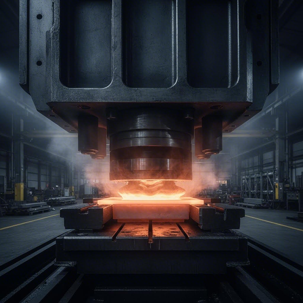
Tässä jotain, mikä saattaa yllättää sinua: vaikka prosessia kutsutaankin nimellä "kylmämuovaus", leikatut osat tulevat usein ulos kuumina. Miten tämä tapahtuu ilman ulkoista lämmitystä?
Vastaus piilee kitkassa. Kun paine laittaa valtavan voiman – usein satojen tonnien luokkaa – työntämään muottia levyyn, syntyvä suuri paine luo kitkaa työkalun ja työkappaleen välille. Tämä kitka tuottaa merkittävää lämpöä leikkausprosessin aikana, vaikka valmistajat eivät käytä ulkoista lämpöenergiaa.
Tällä erottelulla on useita merkityksiä:
- Materiaaliominaisuudet pysyvät stabiileina koska metalli ei koskaan saavuta sellaista lämpötilaa, joka muuttaisi sen molekyyli rakennetta
- Mittatarkkuus paranee koska osat eivät kutistu tai vääry lämpötilan laskiessa
- Tuotantonopeudet kasvavat ilman odotusaikoja lämmitykselle tai jäähdytykselle
- Energian hinnat laskevat vertailuna kuumamuovausvaihtoehtoihin
Umpikuto-operaatio perustuu tarkasti koordinoituun vuorovaikutukseen kolmen elementin välillä: levytyhjä, tarkkuusmuotti ja puristinkone. Kun umpikuvauksessa käytettävä voima mitataan toneina, tarvitaan laitteistoa, joka pystyy ylläpitämään tarkkoja toleransseja – usein niin tiukoja kuin ±0,001 tuumaa teollisuusstandardien mukaan.
Litteästä levystä valmiiksi komponentiksi
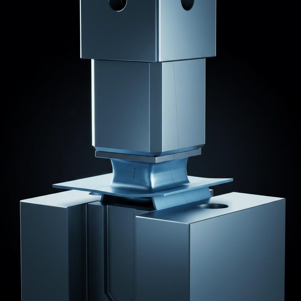
Kuvittele, että syötät koneeseen litteän alumiini- tai teräslevyn ja poimit sieltä sekunnin kuluttua monimutkaisen kolmiulotteisen kiinnikkeen. Tämä on umpikuvauksen toiminnan voima.
Muutos tapahtuu työkalu- ja muottisarjan avulla, joka koostuu kahdesta olennaisesta osasta: vasara (joka kohdistaa alaspäin suuntautuvan voiman) ja muotti (joka muovaa metallia alhaalta päin). Koneen kierrosten aikana nämä komponentit toimivat yhdessä leikaten, taivuttaen, muovaten tai vetäen metallin lopulliseen muotoonsa.
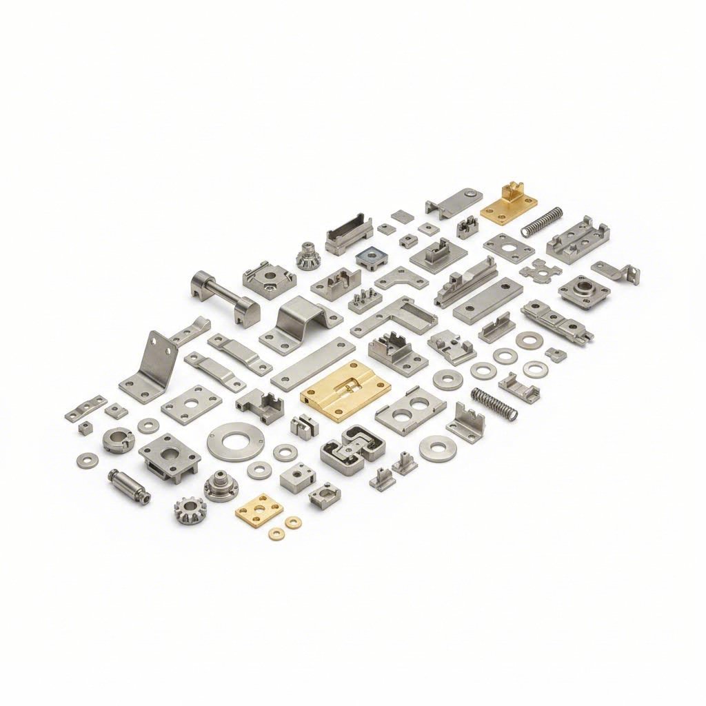
Metallin muokkauksen erityisen arvokkaaksi tekee sen monipuolisuus. Nykyaikaiset muokkauskoneet eivät suorita vain yhtä toimintoa – ne voivat leikata, rei'ittää ja muotoilla raaka-ainetta CNC-ohjelmoinnin avulla, joka takaa johdonmukaisuuden tuhansien tai miljoonien syklujen ajan. Riippumatta siitä, tarvitsevatko valmistajat yksinkertaisia kiinnikkeitä, monimutkaisia elektronisiin komponentteihin vai vaativia autoteollisuuden osia, tämä prosessi tarjoaa nopeuden, tarkkuuden ja skaalautuvuuden, joita muut menetelmät eivät yksinkertaisesti pysty vastaamaan.

Oikean metallin valinta muokkaussovellukseen
Nyt kun ymmärrät, miten muokkaus muuntaa levyt valmiiksi komponenteiksi , tässä on ratkaiseva kysymys: minkä metallin sinun tulisi valita? Oikean metallin valinta muokkaukseen vaikuttaa suoraan kaikkeen osan kestävyydestä valmistuskustannuksiin ja lopulliseen suorituskykyyn.
Totuus on, että kaikki metallit eivät käyttäydy samalla tavalla leikkauskoneessa. Jotkut venyvät helposti halkeamatta. Toiset kovettuvat muovauksessa nopeasti ja vaativat erityiskäsittelyä. Näiden erojen ymmärtäminen auttaa välttämään kalliita virheitä jo ennen työkalujen valmistamista.
Teräsluokat ja niiden leikkausominaisuudet
Teräs on edelleen metallinmuovauksen pääasiallinen materiaali, eikä ilman syytä. Se tarjoaa vertaansa vailla pitävän yhdistelmän lujuutta, muovattavuutta ja edullisuutta, mikä tekee siitä sopivan lukemattomiin sovelluksiin.
Hiiliteräs on yleisimmin käytetty vaihtoehto. Saatavana alhaisissa, keskisissä ja korkeissa hiiliteräsluoksissa, se tarjoaa erinomaisen leikattavuuden kilpailukykyisillä hinnoilla. Alhainen hiilipitoisuus (alle 0,3 % hiiltä) muovautuu helposti ja soveltuu hyvin kiinnikkeisiin, koteloihin ja yleisiin rakennekomponentteihin. Hiilipitoisuuden kasvaessa lujuus paranee, mutta ductility heikkenee – mikä tarkoittaa, että metallia on vaikeampi muovata halkeamatta.
Korkean lujuuden, matalaleakaisin (HSLA) teräs tarjoaa vahvuutta ilman liiallista painoa. Talan Productsin mukaan HSLA-terästä käytetään yleisesti autoteollisuudessa, raskaiden koneiden ja rakenteiden sovelluksissa, joissa sekä lujuus että kevyt paino ovat tärkeitä.
Kun korroosionkesto on olennaisen tärkeää, ruostumattoman teräksen leikkaus on suositumpi vaihtoehto. Eri laadut tarjoavat ainutlaatuisia etuja:
- 300-sarjan ruostumaton (tyypit 301, 302, 305) tarjoaa erinomaisen korroosionkeston ja muovattavuuden elintarviketeollisuuteen, lääkinnällisiin laitteisiin ja arkkitehtonisiin sovelluksiin
- 400-sarjan ruostumaton (luokat 410, 420, 440A) tarjoaa korkeamman kovuuden ja kulumisvastuksen leikkuutyökaluihin ja venttiilien komponentteihin
- Sakkoautuvat lajit (17-4PH, 17-7PH) tarjoavat poikkeuksellisen lujuuden ilmailulle ja puolustusteollisuudelle
Yksi haaste leikatulle teräkselle, erityisesti austeniittisille ruostumattomille teräslaaduille, on niiden korkea kovettumisnopeus. Kuten Ulbrich huomauttaa, austeniittisen ruostumattoman teräksen kylmäkovettumisindeksi on 0,34 %, mikä voi aiheuttaa martensiittimuutoksen muovauksen aikana. Tämä tekee materiaalista haurasta ja halkeamaan alttiin, ellei sitä hallita asianmukaisesti leikkausprosessin aikana.
Kevytsallit painokriittisiin sovelluksiin
Kun jokainen gramma on tärkeä, leikattu alumiini tarjoaa painon vähentämisen rakenteellista lujuutta uhraamatta. Alumiini painaa noin kolmanneksen teräksen painosta, minkä ansiosta se soveltuu erinomaisesti ilmailukomponentteihin, kuluttajaelektroniikkaan ja auton korirakenteisiin, joissa polttoaineen säästö on tärkeää.
Yleisiä alumiinista valmistettavia leikkauslaatuja ovat 1100, 3003, 5052 ja 6061 – jokainen tarjoaa eri tasapainon lujuuden, muovattavuuden ja korroosionkestävyyden välillä. Alumiini leikataan puhtaasti ja se muovautuu helposti, vaikka sen leikkaamiseen vaaditaan huolellinen työkalujen suunnittelu, jotta estetään galling (materiaalin siirtyminen työkappaleen ja työkalun välillä).
Muut, joissa on vähintään 50 painoprosenttia erinomaisia sovelluksissa, joissa vaaditaan sähkö- tai lämmönjohtavuutta. Kuparin leikkaus on välttämätöntä sähköliittimissä, virtapalkkeissa ja lämmönvaihtimissa. Messinki – kupari-zinkki-seos – tarjoaa samankaltaisen johtavuuden parantuneen konepellattavuuden kanssa, mikä tekee siitä suosittua liittimiin, koskettimiin ja ilmastointijärjestelmien komponentteihin.
Erityisen vaativiin sovelluksiin, titanium tarjoaa poikkeellisen suhteen lujuus–paino sekä korroosionkestävyyden ja biokompatibilisuuden. Vaikka titaania on vaikeampi leikata kuin terästä tai alumiinia, titaanilaadut kuten 6AL4V määritellään yhä useammin ilmailu-, sotilas- ja lääketieteellisten implanttien sovelluksiin.
Materiaalien ominaisuuksien sovittaminen osan vaatimuksiin
Parhaan materiaalin valitseminen edellyttää neljän kriittisen ominaisuuden arviointia, jotka vaikuttavat suoraan muovattavuuteen:
- Muovautuvuus ja muokattavuus määrittävät, kuinka paljon metallia voidaan venyttää ennen kuin se murtuu. Muovaus tapahtuu materiaalin myötörajan ja vetolujuuden välillä – jos vetolujuus ylittyy, halkeamia ilmenee
- Vetolujuus mittaa voimavastusta. Korkeamman lujuuden materiaalit kestävät suurempia kuormituksia, mutta niillä on tyypillisesti pienempi muovausikkuna
- Työhön kovettuminen osoittaa, kuinka nopeasti metalli muuttuu kovemmaksi ja hauraammaksi leikkauksen aikana. Suuren työkovettumisnopeuden materiaaleissa saattaa olla tarpeen välihöyrystys
- Paksuusalue vaikuttaa siihen, mikä leikkausmenetelmä sopii parhaiten – ohuet materiaalit soveltuvat etenevien muottien käyttöön, kun taas paksuimmille materiaaleille saattaa tarvita nestepaineistapinaa hitaammalla muovausnopeudella
| Materiaalilaji | Tyyppinen paksuusalue | Tärkeitä ominaisuuksia | Parhaat käyttösovellukset | Suhteellinen hinta |
|---|---|---|---|---|
| Hiiliteräs | 0,010" - 0,250" | Korkea lujuus, erinomainen muovattavuus | Kiinnikkeet, kotelot, rakennedelit | Alhainen |
| Ruostumaton teräs | 0,005" - 0,187" | Korroosionkestävyys, kestävyys | Lääkintälaitteet, elintarviketeollisuuden varusteet, ilmailu | Keski-Suuri |
| Alumiini | 0,2 - 4,8 mm | Kevyet, korroosionkestävät | Elektroniikka, autoteollisuuden paneelit, ilmailu- ja avaruusteollisuus | Keskikoko |
| Kupari | 0,13 - 3,2 mm | Erinomainen sähkön- ja lämmönjohtavuus | Liittimet, virtapenkereet, lämmönsiirtimet | Keski-Suuri |
| Messinki | 0,010" - 0,125" | Hyvä johtavuus, korkea konepellisuus | Terminaaleja, koskettimia, koristekomponentteja | Keskikoko |
| Titanium | 0,25 - 2,0 mm | Korkea lujuus-painosuhde, biyhteensopiva | Ilmailu- ja avaruusteollisuus, lääketieteelliset implantit, puolustusteollisuus | Korkea |
Materiaalin paksuus vaikuttaa merkittävästi prosessin valintaan. Ohuet levyt (alle 0,060") soveltuvat yleensä hyvin korkeanopeuksisiin etenemäväsäviin, kun taas paksummille materiaaleille tarvitaan usein hitaampia hydraulisia puristimia, jotka tarjoavat parempaa voiman säätöä syvävetoprosesseissa.
Kun materiaali on valittu, seuraava kriittinen päätös koskee oikean puristintyypin valintaa, jotta saadaan tarvittava voima, nopeus ja säätö sovellukseesi.
Levyjen painatuspuristimien tyypit ja milloin kumpaakin tulisi käyttää
Olet siis valinnut täydellisen materiaalin projektillesi. Nyt nousee esiin kysymys, joka voi tehdä tai rikkoa tuotannon tehokkuuden: mikä on painatuspuristin, ja mitä tyyppiä sinun tulisi käyttää?
Painatuspuristin on voimanlähde, joka tarjoaa tarvittavan voiman litteän levyn muuntamiseksi valmiiksi komponenteiksi. Mutta tässä se, mitä monet ihmiset eivät huomaa – kaikki metallipainatuspuristimet eivät toimi samalla tavalla. Valitsemasi puristin vaikuttaa kierrosaikoihin, osien laatuun, energiankulutukseen ja pitkän aikavälin käyttökustannuksiin.
Nykyisen markkinan tarjoaa kolme pääasiallista puristusteknologiaa: mekaaninen, hydraulinen ja servopaine. Jokaisella on omat etunsa materiaalista, osien monimutkaisuudesta ja tuotantomäärävaatimuksista riippuen.
Mekaaniset pressit korkean nopeuden tuotantoon
Tarvitsetko nopeutta? Mekaaniset pressit ovat usein paras valinta. Nämä koneet käyttävät pyöräväräytintä käyttävää mekanismia voiman tuottamiseen, mikä tekee niistä ideaalin vaihtoehdon suurtilavuustuotannossa, jossa syklin kesto on tärkeintä.
Pyöräväräytin varastoi pyörimisenergian, jonka pressi vapauttaa kunkin iskun aikana koplan ja kampiakselin kautta. Tämä rakenne tarjoaa johdonmukaista ja toistettavaa voimaa erinomaisella nopeudella – jotkin mekaaniset pressit saavuttavat yli 1 000 iskua minuutissa pienille osille.
Mekaanisten pressien keskeisiä etuja ovat:
- Erinomainen tuotantonopeus levyjen leikkaukseen, reikien punchaukseen ja matalaan muovaukseen
- Alempi energiankulutus kunhan pyöräväräytin on saavuttanut käyttönopeuden
- Ennustettavat iskunmallit jotka takaavat johdonmukaisen osalaadun miljoonien syklien ajan
- Pienemmät ylläpitokustannukset verrattuna hydraulijärjestelmiin
Kuitenkin mekaanisilla puristimilla on rajoituksia. Eigen Engineeringin mukaan yksi haittapuoli on, että niillä ei ole yhtä paljon hallintaa iskun alaosassa. Tämä tekee niistä vähemmän sopivia syvävetoon tai toimenpiteisiin, jotka vaativat muuttuvaa voimaa muovauksen syklin aikana. Ne soveltuvat erinomaisesti tilanteisiin, joissa työ edellyttää johdonmukaisia, toistuvia toimenpiteitä ja tuotantotilavuus painaa joustavuutta.
Hydraulijärjestelmät monimutkaisiin muovausoperaatioihin
Kun käsittelet raskaampia tai korkean vetolujuuden materiaaleja, hydraulipuristimet ovat suositumpi vaihtoehto. Nämä koneet käyttävät nestepainetta voiman tuottamiseen, tarjoten ominaisuuksia, joita mekaaniset puristimet eivät yksinkertaisesti pysty vastaamaan.
Hydraulisten metallilevyjen muokkauspainemallien erottaa niiden voiman säätö. Toisin kuin mekaaniset puristimet, jotka tuottavat voimaa pyörävän painoradan liikemäärän perusteella, hydraulijärjestelmät soveltavat tasaisesti painetta koko iskun ajan. Tämä ominaisuus on erinomaisen arvokas seuraavissa tapauksissa:
- Syvän vetämisoperaatioissa joissa ohjattu materiaalin virtaus estää repäisyt
- Monimutkaisiin kolmiulotteisiin muotoihin joissa vaaditaan muuttuvaa voimansovellusta
- Paksuissa tai korkean lujuuden materiaaleissa joita on vaikea muovata
- Operaatioissa, joissa vaaditaan pidennettyä lepohetkeä iskun alaosassa
Hydraulipainemallit ovat hitaampia kuin mekaaniset mallit, mutta ne kompensoivat hitauttaan paremmalla monikäyttöisyydellä ja tarkkuudella. Tämä kompromissi on järkevä, kun valmistetaan monimutkaisia levyosia, joissa tarkkuus on tärkeämpi kuin pelkkä nopeus.
Servoteknologia edistää levytyksen tarkkuutta
Servopuristin edustaa uusinta kehitysvaihetta leikkausteknologiassa. Nämä koneet yhdistävät edistyneen servomoottoritekniikan ohjelmoitavaan ohjaamiseen tarjoten nopeutta, tehoa ja sopeutuvuutta samassa paketissa – ominaisuuksia, joita ei voida saavuttaa pelkillä mekaanisilla tai hydraulisilla puristimilla.
Servopressien edut sisältävät:
- Täysin ohjelmoitavat iskun profiilit jotka optimoivat muovauksen jokaiselle yksilölliselle osalle
- Muuttuvan nopeuden hallinta iskun aikana—nopea lähestyminen, hidas muovaus, nopea paluu
- Energiatehokkuus koska moottori ottaa virtaa vain tarvittaessa
- Nopea vaihto eri osio-ohjelmien välillä ilman mekaanisia säätöjä
- Alhaisemmat melutasot verrattuna perinteisiin mekaanisiin järjestelmiin
Valmistajille, jotka tuottavat elektroniikkaa, lääketarvikkeita tai tarkkuusleikattuja metalliosia, servoteknologia tarjoaa vaativiin toleransseihin vaadittavan tarkkuuden. Parametrien nopea säätökyky tekee servopuristimista myös erinomaisen vaihtoehtoisen työpajoille, jotka käsittelevät monipuolisia tuotevalikoimia.
Puristusvoiman tarpeen ymmärtäminen
Riippumatta siitä, minkä tyyppistä puristinta valitset, on tärkeää ymmärtää painovoima. Painovoimakapasiteetti kuvaa suurinta voimaa, jonka puristin voi kehittää rakenteellisesta vahingosta johtuen. Mutta tässä se, mitä monet leikkaajat sivuuttavat: tarvittava painovoima on pysyttävä puristimen käytettävissä olevan painovoimakäyrän alapuolella jokaisessa iskussa – ei ainoastaan alaosassa.
Kuten Guangduan Presses selittää, että puristimen painovoimakapasiteetti vaihtelee koko iskusyklin ajan. Ylimmässä ja alimmassa kuolokohdassa teoreettinen käytettävissä oleva painovoima lähestyy ääretöntä – mutta rakenne pettäisi paljon ennen näitä ääripisteitä. Käytännön painovoimaraja riippuu iskun sijainnista, materiaalin paksuudesta ja osan geometriasta.
Valitessasi teräspuristinta tai mitä tahansa leikkauslaitetta, ota huomioon nämä tekijät:
- Materiaalin tyyppi ja vetolujuus —kovemmat materiaalit vaativat suurempaa voimaa
- Materiaalin paksuus —paksu tukki vaatii korkeampaa painovoimaa
- Osaen kompleksisuus —useat taivutukset tai muotoudut moninkertaistavat voimatarpeet
- Leikkauskehä —pidemmät leikkaukset vaativat suhteellisesti enemmän painovoimaa
| Painelaite | Nopeusalue | Voimankontrolli | Parhaat käyttösovellukset | Painovoimatarkastelut |
|---|---|---|---|---|
| Mekaaninen | 20–1 500+ SPM | Kiinteä iskuprofiili, rajoitettu alareunan ohjaus | Suurtilavuusleikkaus, rei'itys, matala muotoilu | Saatavilla oleva painovoima vaihtelee iskun aseman mukaan; huippu lähellä alinta kuolleetta |
| Hydraulinen | 5–50 SPM | Koko painovoima saatavilla koko iskun matkalta | Syvävetoperäys, monimutkainen muovaus, paksut materiaalit | Vakioitu voima missä tahansa iskun kohdassa; ideaali raskaiden kalvojen työhön |
| Servo | 10–300+ SPM | Täysin ohjelmoitavat nopeus- ja voimakäyrät | Tarkkuusosat, muuttuva tuotanto, nopea vaihto | Optimoitu voiman siirto vähentää huippivoimavaatimuksia |
Oikea metallin painopuristin riippuu tarpeidesi tasapainottamisesta. Jos suuritehoinen tuotanto yhdenmukaisten osien kanssa on toimintasi keskiössä, mekaaniset puristimet tarjoavat vertaansa vailla nopeutta. Monimutkaisempaa muovauksen voimasäätöä varten hydraulijärjestelmät tarjoavat tarvittavaa joustavuutta. Ja kun tarkkuus ja ohjelmoitavuus ovat tärkeimmillä, servoteknologia tarjoaa molempien parhaat puolet – vaikkakin korkeammalla alkuperäisellä sijoituksella.
Kun materiaali on valittu ja puristintyyppi määritelty, seuraavana askeleena on ymmärtää ne tarkat painoleikkuuoperaatiot, jotka muuntavat raakalevyn valmiiksi komponenteiksi.
Olennaiset leikkuuoperaatiot alkaen leikkaamisesta kokoonpanoon
Olet valinnut materiaalisi ja valinnut oikean puristimen. Nyt nousee kysymys, joka määrittää valmiiden osiesi ulkonäön: mitä leikkausoperaatioita sinulla todella tarvitaan?
Useimmat oppaat luettelevat seitsemästä yhdeksään perusoperaatioon ja pysähtyvät siihen. Mutta tässä on totuus – onnistunut metallin leikkuuprosessien suunnittelu edellyttää koko käytettävissä olevien tekniikoiden hahmottamista, mukaan lukien toissijaiset operaatiot, jotka muuntavat leikatut alustat kokoonpanovalmiiksi komponenteiksi.
Käydään läpi kaikki operaatiot, jotka sinun tulisi tuntea, ryhmiteltynä toiminnon mukaan, jotta voit tunnistaa tarkalleen mitä projektillesi vaaditaan.
Leikkausoperaatiot, jotka määrittävät osien reunat
Jokainen leikattu osa alkaa leikkausoperaatioilla, jotka erottavat materiaalin tai luovat aukkoja. Nämä operaatiot poistavat metallia muotoilematta sitä, ja ne määrittävät osan peruskontuurin ja ominaisuudet.
- Leikkaus — Perusleikkausoperaatio, jolla tasainen työkappale (tyhjäkappale) erotetaan emolevystä. Kun metallia leikataan tyhjäkappaleeksi, ulos painettu kappale muodostaa valmiin osan, kun taas jäljelle jäävä runko muodostaa romun. Tyhjäkappaleen leikkaus muodostaa lähtökohdan melkein kaikille seuraaville muovausoperaatioille.
- Avaus — Tyhjäkappaleen leikkauksen käänteisoperaatio. Tässä ulos painettu materiaali muodostaa romun, kun taas reiällinen levy muodostaa työkappaleen. Reikien punchaaminen luo kiinnitysreikiä, ilmanvaihtoaukkoja tai painonvähentäviä ominaisuuksia muovattuihin komponentteihin.
- Kaari — Poistaa materiaalia tyhjäkappaleen reunalta eikä sen sisäosasta. Reunaleikkaus valmistaa osia seuraavia taivutusoperaatioita varten poistamalla materiaalin, joka muuten haittaisi muovauksen suorittamista.
- Leikkaus — Leikkaa suoria viivoja levymetallissa ilman suljettuja muotoja. Leikkaus erottelee yleensä valmiit osat nauhasta tai leikkaa ylimääräisen materiaalin muovattujen komponenttien reunoilta.
- Leikkaus — Luo osittaisen leikkauksen, jossa toinen sivu pysyy kiinnittyneenä, muodostaen luukkuja tai nippelöitä. Toisin kuin lävistys, lanssiminen ei poista materiaalia – se siirtää sitä luodakseen toiminnallisia ominaisuuksia.
- Trimmaus — Poistaa ylimääräisen materiaalin syvävetämällä valmistetuista tai muotoilluista osista. Syvävetokomponenteissa on usein tarpeen trimmata lopullisia mittoja varten, kun muotoutumisprosessi venyttää materiaalia epätasaisesti.
Mitä metallille tapahtuu leikatessa? Metallin painamisprosessi altistaa materiaalin voimakkaalle leikkausjännitykselle, joka keskittyy leikkuureunaa pitkin. Tämä jännitys ylittää materiaalin leikkauslujuuden, aiheuttaen murtumisen. Tuloksena olevassa reunassa näkyy erottuvia vyöhykkeit: kiillotettu alue, jossa nuppi ensimmäisen kerran koskettaa metallia, ja sen jälkeen murtumavyöhyke, jossa materiaali irtoaa.
Muototekniikat, jotka muodostavat kolmiulotteisia muotoja
Leikkaus määrittää rajat, mutta muovausoperaatiot antavat leikattujen osien toiminnallisen geometrian. Nämä menetelmät muokkaavat metallia poistamatta materiaalia – venyttämällä, puristamalla ja taivuttamalla sitä kolmiulotteisiin muotoihin.
- Kääntyminen — Yleisin muovausoperaatio. Taivutus kohdistaa voiman lineaariseksi akseliksi luodakseen kulmat levyyn. Toisin kuin painantaan liittyvät taivutusoperaatiot (alla käsitellään), standarditaivutus sallii jonkin verran kimmoista paluuliikettä, kun materiaali osittain palautuu paineen jälkeen.
- Piirustus — Muuntaa tasomaiset tyhjennyslevyt kuppi- tai laatikkomaisiksi komponenteiksi vetämällä materiaalia muottikoloonsa. Syvävetämistä – jossa syvyys ylittää halkaisijan – vaatii tarkkaa materiaalivirran hallintaa rypistymisen tai repeämisen estämiseksi. Mukaan Wikipedia , vetämisen aikana syntyy tribologinen prosessi, joka aiheuttaa kitkaa ja edellyttää voiteluaineita työkalujen ja kappaleiden pintojen suojaamiseksi vaurioilta.
- Keksiminen — Käyttää äärimmäistä painetta puristaakseen metallin täysin kaikkien muottikavennuksen yksityiskohtien sisään. Kolotus terästä tai muita metalleja poistaa kimpoamisen muovautumalla materiaali myötörajan ylitse koko sen paksuuden läpi. Tulos? Erityisen tarkat piirteet tiukkojen toleranssien kanssa. Levymetallin kolotus tuottaa ne terävät yksityiskohdat, joita näet valuutassa ja tarkkuuskomponenteissa.
- Koriste — Luo korostuvia tai syvennettyjä suunnitelmia levymetallissa merkittävän paksuudenmuutoksen sijaan. Painonnosto lisää logot, jäykistäviä ripustuksia tai koristeellisia kuosioita tasopaneelien pintaan.
- Reunustus — Taivuttaa materiaalia kaarevan reunan mukaan suoran viivan sijaan. Reunustaminen luo jäykistetyt reunaosat, kiinnityskohdat tai liitospinnat muotoiltuihin osiin.
- Tasaus — Ohentaa ja venyttää vedettyjen kuppien seiniä ajamalla materiaalin pienemmän raon läpi kuin alkuperäinen seinämän paksuus. Rengastus tuottaa yhtenäisen seinämän paksuuden syvälle vedetyissä säiliöissä.
- Swaging — Vähentää putkimaisen tai sauvamaisen komponentin halkaisijaa säteittäisellä puristuksella. Osa-alueiden muovaus luo kavennettuja osia tai liitoskohdat leikatuille osille.
Miten nämä toiminnot vaikuttavat materiaaliprosesseihin? Jokainen muovausmenetelmä lujuuttaa metallia eri tavoin. Taonta keskittää jännitteen taiteviivaan, kun taas syvävetäminen jakaa muodonmuutoksen suuremmille alueille. Kolikkopuristus aiheuttaa voimakkaimman lujuuden kasvun äärimmäisten paineiden vuoksi. Näiden ilmiöiden ymmärtäminen auttaa insinöörejä ennustamaan valmiin osan ominaisuuksia ja tunnistamaan, missä jännitysten lievitys saattaa olla tarpeen.
Toissijaiset toiminnot, jotka saattavat valmistussyklin päätökseen
Tässä kohtaa leikkaus- ja painoleikkuukyvyt laajenevat pitemmälle kuin useimmissa oppaissa käsitellään. Toissijaiset toiminnot muuntavat leikatut levyosat toiminnallisiksi kokoonpanoiksi, jotka ovat valmiita asennettavaksi.
- Munkkailu — Luo sisäkierret poratuissa rei'issä. Työkalussa tapattava kierretys suorittaa tämän toimenpiteen etenemällä työkalua käyttäen, mikä poistaa erilliset käsittelyvaiheet. Kun Decimal Engineering huomautukset: sisämuottainen kierreporaus vähentää merkittävästi kappalekohtaista kustannusta yhdistämällä useita toimintoja yhdeksi puristuskiertoksi.
- Hitsaus — Yhdistää leikattuja komponentteja pisteköytämisellä, projektioköytämisellä tai saumaköytämisellä. Vastusköytäminen integroituu erinomaisesti leikkuutuotantolinjoihin ja lisää rakenteellisia liitoksia ilman tuotannon hidastumista.
- Välilevyn asennus — Asentaa PEM-mutterit, -sylinterit, -etäisyyspalkit ja muut kiinnittimet leikattuihin osiin. Painolevät kiinnittimet poistavat tarpeen irtoavien kiinnittimien käytöstä lopputuotantovaiheessa.
- Naulaus — Yhdistää pysyvästi useita leikattuja komponentteja kiinteillä tai putkimaisilla niveloilla. Itsepuristavat niveltäjät voivat yhdistää erilaisia materiaaleja ilman esiporattuja reikiä.
- Korkkaus — Poistaa terävät reunat ja porauskärjet, jotka syntyvät leikkaustoimintojen aikana. Reunojen ja kärkien poisto suojaa kokoonpanotyöntekijöitä, parantaa ulkoasua ja estää häiriöitä vastinosien asennuksessa.
- Kokoonpanointegraatio — Yhdistää useita leikattuja komponentteja ei-leikattuihin elementteihin (muovit, elektroniikka, tiivisteet) muodostaen valmiita alakokoonpanoja. Arvonlisäkokoonpano vähentää asiakkaan käsittely- ja logistiikkakustannuksia.
Miksi jälkikäsittelytoiminnot ovat tärkeitä? Ne muuntavat leikkaamisen osien valmistuksesta täydelliseksi valmistusratkaisuksi. Leikkaaja, joka hoitaa kierteityksen, hitsauksen ja kokoonpanointegraation, toimittaa valmiita komponentteja eikä puolivalmiita levyosia – mikä vähentää toimitusketjun monimutkaisuutta ja kokonaiskustannuksia.
Miten toiminnot yhdistyvät tuotannossa
Yksittäisiä toimintoja harvoin suoritetaan eristyksissä. Esimerkiksi edistävässä työkalussa suoritetaan useita leikkaus- ja muovausvaiheita peräkkäin, kun nauhamateriaali etenee työkalun läpi. Yksi edistävä työkalu voi esimerkiksi leikata ulkopohjan, porata kiinnitysreikiä, muovata jäykisteitä, taivuttaa reunoja ja puristaa tarkkoja mittoja – kaikki yhdessä puristussyklissä.
Toimintojen järjestyksellä on kriittinen merkitys. Työkappaleen muotoilu tapahtuu yleensä ensin. Reikien poraaminen seuraa usein, kun materiaali on edelleen tasainen. Muovausoperaatiot etenevät kohtalaisimmista vakavimpiin, ja lopullisiin vaiheisiin varataan vaativa puristus, jonka äärimmäiset paineet eivät vääristä myöhempiä ominaisuuksia.
Tämän koko valikoiman leikkausoperaatioiden ymmärtäminen – alkaen alkuperäisestä työkappaleen leikkaamisesta sekundaariseen kokoonpanoon asti – auttaa sinua viestimään tehokkaasti toimittajien kanssa ja tekemään perusteltuja päätöksiä siitä, mitkä ominaisuudet projektillesi todella tarvitaan.
Kun saat selkeän kuvan käytettävissä olevista operaatioista, seuraava päätös liittyy oikean leikkuumenetelmän valintaan – jatkoleikkuri, siirtokannatin, nelisivuinen taivutin tai tarkka leikkaus – jotta kyseiset operaatiot voidaan suorittaa tehokkaasti vaaditulla tuotantomäärällä.
Oikean leikkuumenetelmän valitseminen projektiisi
Ymmärrät toiminnan. Tiedät, mitä osillesi tarvitaan. Nyt tulee päätös, joka määrittää projektisi menestyksen: mikä vaivutusmenetelmä tuottaa parhaat tulokset tietyille vaatimuksillesi?
Tämä valinta on enemmän kuin vain tarkistuslistan käyttö teknisissä tiedoissa. Valitsemasi valmistusvaivutusprosessi vaikuttaa työkaluinvestointiin, tuotantoaikatauluun, osien laatuun ja lopulta kappalekohtaiseen hintaan. Tee se oikein, ja sinulla on kilpailuetu. Tee se väärin, ja joudut epätehokkaaseen prosessiin koko tuotteen elinkaaren ajan.
Tarkastellaan neljää pääasiallista levyvaivutusprosessin menetelmää ja niitä kriteerejä, jotka tulisi ohjata valintaa.
Jatkuvavaivutus suurten sarjojen tehokkuuteen
Kuvittele metallinauha, joka etenee jatkuvasti useiden asemien läpi, joissa jokainen suorittaa tietyn toimenpiteen – leikkaa, muovaa, taivuttaa – kunnes valmis osa putoaa pois lopussa. Tämä on edistyneen vaaran ja painamisen toimintaperiaate, ja se on tuotantomenetelmänä ensisijainen vaihtoehto, kun tuotantomäärät oikeuttavat työkaluihin tehtävään sijoitukseen.
Miten se toimii? Keloiltansa syötetään automaattisesti metallinauha painokoneeseen, joka etenee tarkasti määrätyn matkan (jaon) joka iskun aikana. Jokaisessa asemassa erikoistuneet työkalut suorittavat yhden toimenpiteen, kun osa pysyy kiinni kantavan nauhan varassa. Vasta viimeisessä asemassa valmis komponentti irrotetaan liuskasta.
Edistyneen vaaran painaminen soveltuu erinomaisesti projekteihin, jotka sisältävät:
- Suuret tuotantomäärät —tyypillisesti yli 10 000 kappaletta vuodessa, jolloin työkalukustannukset alentuvat nopeasti
- Pienet ja keskikokoiset osat jotka mahtuvat standardikokoisiin painokoneen alustoihin
- Kohtalainen monimutkaisuus useiden leikkaus- ja muovausvaiheiden vaatiminen
- Vakioitu kysyntä joka oikeuttaa erityisvälineisiin
Edut ovat vakuuttavia. Die-Maticin mukaan etenevä leikkaus tarjoaa tuotantonopeutta, nopeita sykliaikoja, alhaisemmat työkustannukset ja pienemmät yksikkökustannukset. Joidenkin toimintojen syklinopeudet saavuttavat jopa yli 1 000 iskua minuutissa pienille osille.
Kuitenkin rajoituksia on olemassa. Alustava välinkehitys on kalliimpaa kuin muilla menetelmillä – etenevät muotit ovat monimutkaisia, tarkkuusvaatimukseltaan korkeita laitteita, jotka vaativat merkittävää suunnittelu- ja valmistusaikaa. Kun ne on kerran rakennettu, suunnitusten muutokset tulevat kalliiksi ja aikaa vieviksi. Erittäin syvät muotoudut tai erittäin monimutkaiset geometriat voivat ylittää sen, mitä etenevällä välineellä voidaan saavuttaa.
Siirtomuottiratkaisut suurille ja monimutkaisille osille
Mitä tapahtuu, kun osat kasvavat liian suuriksi eteneville muoteille, tai kun geometriat vaativat syvempää muotoutumista kuin kuljettimenauhamenetelmät sallivat? Siirtomuottileikkaus tarjoaa ratkaisun.
Toisin kuin etenevä vaivaus, siirtokuvit joko alkavat esileikatuista levyistä tai erottavat osan nauhasta ensimmäisessä asemassa. Mekaaniset sormet tai siirtorailit siirtävät sen jälkeen vapaata työkappaletta seuraaviin asemiin lisätoimenpiteitä varten. Tämä "vapaa" osa -menetelmä mahdollistaa ominaisuuksia, joita yhteydessä olevat nauhamenetelmät eivät pysty saavuttamaan.
Siirtovaivauksen edut näkyvät erityisesti:
- Suurissa osissa joiden käsittely vaatisi liian leveitä eteneviä kuveja
- Syvävetokomponenteissa joissa tarvitaan useita vetotoimenpiteitä välillä olevalla hehkutuksella
- Monimutkaisiin kolmiulotteisiin muotoihin joihin tarvitaan pääsyä useista kulmista
- Osat, joihin tarvitaan toimenpiteitä molemmilta puolilta työkappaleesta
Metallin vaivauksen tuotantiedut sisältävät joustavuuden monimutkaisille geometrioille ja kyvyn käsitellä paksumpia levyjä. Siirtokuvit soveltuvat myös osiin, joita etenevät työkalut eivät yksinkertaisesti voi valmistaa – ajattele autojen runko-osia, rakenteellisia kiinnikkeitä tai syviä kotelointeja.
Komпромisseja ovat hitaammat syklinopeudet verrattuna edistyneempiin menetelmiin sekä korkeammat kappalekustannukset kohtuullisilla tuotantomäärillä. Mekaaniset siirtöjärjestelmät lisäävät monimutkaisuutta, ja työkalukustannukset pysyvät merkittävinä. Siirtoutopuristus on järkevä vaihtoehto keskikokoisille tai suurille määrille monimutkaisia osia, joiden geometria oikeuttaa sijoituksen.
Fourslide- ja Multislide-menetelmä monimutkaisiin pieniin osiin
Joskus osat vaativat taivutuksia ja muotoilua useista eri suunnista, mikä on haasteellista perinteisille pystysuorille puristeille. Fourslide- (tai multislide-) puristus ratkaisee ongelman eri tavalla – käyttäen vaakasuoria liukuja, jotka muotoilevat työkappaletta neljästä tai useammasta kulmasta yhtä aikaa.
Tämä menetelmä soveltuu parhaiten:
- Pieniin, monimutkaisiin osiin monimutkaisilla taivutussarjoilla
- Komponentteihin, jotka vaativat monisuuntaista muovaukset yhden operaation sisällä
- Lankamuotoihin ja levyjousiin kolmiulotteisilla konfiguraatioilla
- Alhaiset keskisuuret määrät joissa työkalujen joustavuus on tärkeämpää kuin suora nopeus
Mikä tekee nelisivusta erityiseksi? Vaakasuuntaiset työkaluliukut voivat muovata, taivuttaa ja rei'ittää useista suunnista ilman, että työkappaletta tarvitsee uudelleen sijoittaa. Tämä ominaisuus mahdollistaa geometrioiden valmistuksen, jotka perinteisillä menetelmillä vaatisivat useita vaiheittaisia muottiasemia tai lisätoimenpiteitä.
Nelisivun painaminen tarjoaa myös taloudellisia etuja prototyyppituotannossa ja lyhyissä sarjoissa. Työkalukustannukset ovat yleensä alhaisemmat kuin vaiheittaisissa muoteissa, koska muovausvälineet ovat yksinkertaisempia ja sopeutuvampia. Suunnitelmamuutokset voidaan usein toteuttaa muuttamalla yksittäisiä liukuja kokonaisten muottisarjojen uudelleenrakentamisen sijaan.
Rajoitukset liittyvät osien kokoonsa – nelisivu toimii parhaiten pienille komponenteille – sekä hitaampaan tuotantonopeuteen verrattuna korkean nopeuden vaiheittaisiin prosesseihin. Myös materiaalin paksuus on rajoitettu; paksuilla metalleilla tarvittavat voimat ylittävät vaakasuuntaisten liukujen kapasiteetin.
Tarkka leikkaus, kun tarkkuusvaatimukset ovat tiukat
Vakioleikkaus- ja rei'itystoiminnot tuottavat reunat, joissa on tyypillisiä leikkausvyöhykkeitä ja murtoreunoja. Monissa sovelluksissa tämä reunalaatu on täysin hyväksyttävää. Mutta mitä vaaditaan osille, joissa tarvitaan sileitä, suoria reunoja vähimmäismurrolla? Tässä tilanteessa tarkkuuslyönti tarkka-leikkauksella tulee olennaiseksi.
Tarkka leikkaus käyttää erikoistunutta kolmiosaisesti toimivaa työkalua: V-renkaan muotoinen kiinnitysrengas lukitsee materiaalin leikkuualueen ympärille, samalla kun alapuolelta tuleva vastapaine tukee levyä leikkauksen aikana. Tuloksena? Kokonaan leikatut reunat, jotka ovat lähes koneistettujen pintojen tasoisia.
Tarkka leikkaus tuottaa erinomaisia tuloksia seuraaviin sovelluksiin:
- Hammaspyörät ja ketjupyörät vaativat tarkkoja hampaiden profiileja
- Turvallisuuskriittiset autonosat kuten turvavyön toimintamekanismit ja jarruosat
- Osat, jotka vaativat tiukkoja tasomaisuusvaihteluiden toleransseja levyn koko pinnalla
- Komponentit, joissa toissijainen reunavikojen viimeistely olisi kustannuksiltaan kohtuutonta
Kuten Die-Matic selittää, tarkkuusleikkaus poistaa tarpeen laajalle jälkikäsittelylle, kuten kiillotukselle tai hionnalle, säästäen sekä aikaa että tuotantokustannuksia. Menetelmä mahdollistaa myös johdonmukaisen osien toistettavuuden suurissa tuotantoerissä.
Mikä on kompromissi? Korkeammat kappalekustannukset erikoistuneen työkaluvälineistön ja korkeapaineisen laitteiston vuoksi. Työkalujen kehitykseen liittyy myös pidemmät läpimenoajat. Tarkkuusleikkaus kannattaa taloudellisesti suurten sarjojen tarkkuuskomponenttien valmistuksessa, joissa reunan laatu vaikuttaa suoraan toimintaan tai turvallisuuteen.
Prototyyppien ja lyhyiden tuotantosarjojen huomioonottaminen
Tässä se, mitä useimmat oppaat sivuuttavat: ei jokainen projekti edellytä suurten sarjojen tuotantotyökaluja. Varhaiset prototyypit, välietuotanto ja erikoiset pienet sarjat vaativat erilaisia lähestymistapoja.
Prototyyppeihin ja lyhyisiin sarjoihin kannattaa harkita näitä vaihtoehtoja:
- Pehmeä työkalu —Työkalut, jotka on valmistettu halvemmista materiaaleista ja joissa luovutaan kestosta alhaisemman alkukustannuksen vuoksi
- Modulaariset muottijärjestelmät —Standardisoidut muottisarjat vaihdettavilla inserteillä, jotka vähentävät räätälöityjen työkalujen tarvetta
- Konepohjainen määritys —Erittäin pienille tuotantomäärille, joissa stampausmuottien kustannukset eivät ole perusteltuja. Lutcon mukaan CNC-koneet tarjoavat nopeamman käyttöönoton eivätkä vaadi viikkoja kestävää muottikehitystä, kuten stampaus.
- Laserleikkaus yhdistettynä taivutukseen —Tuottaa stampauksen kaltaisia osia ilman erikoistyökaluja
Kynnysarvo, jossa stampaustuotanto alkaa olla taloudellisempi kuin koneistus, riippuu osan monimutkaisuudesta, materiaalikustannuksista ja vaadituista toleransseista. Yksinkertaiset osat voivat oikeuttaa stampausmuottien käytön jo muutamalla tuhannella kappaleella; monimutkaisemmat geometriat saattavat vaatia kymmeniätuhansia kappaleita ennen kuin investointi kannattuu.
Päätöksenteon viitekehys: menetelmän yhdistäminen vaatimuksiin
Optimaalisen levymetallin stampausprosessin valinta edellyttää neljän keskeisen tekijän tasapainottamista:
Kustannusnäkökohdat ulkottuvat työkaluinvestoinneista. Kyllä, edistyneet vaivat maksavat enemmän alussa verrattuna fourslide-työkaluihin. Mutta kappalekustannukset suurissa volyymeissä suosivat usein korkeampaa alkuperäistä investointia. Arvioi kokonaiskustannus odotetun tuotannon elinkaaren ajan, äläkä keskity vain ensimmäisen vuoden kuluihin.
Määrävaatimukset vaikuttavat suoraan menetelmän valintaan. Suuret tuotantovolyymit perustelevat monimutkaisen edistyksellisen työkaluvälineistön käytön. Pienemmät volyymit suosivat joustavampia menetelmiä, kuten fourslide- tai pehmeästi työsteltyjä ratkaisuja, jotka uhraavat nopeuden pienemmän alkuperäisen investoinnin vuoksi.
Laatu ja toleranssitarpeet voivat määrätä menetelmäsi riippumatta volyymistä. Jos sovelluksesi edellyttää tarkasti leikattuja reunoja tai kolhattuja tarkkuusominaisuuksia, nämä vaatimukset ohittavat pelkän kustannustehokkuuden.
Aikarajoitteet vaikuttavat sekä työkalujen kehitykseen että tuotantoon. Edistyneillä vaiveilla on pisin kehitysjakso, mutta ne tarjoavat nopeimmat tuotantonopeudet. Fourslide-työkalut kehittyvät nopeammin, mutta niiden tuotantonopeus on hitaampi. Prototyyppimenetelmillä voidaan aloittaa välittömästi, mutta niitä ei voida skaalata.
| Menetelmä | Osaen kompleksisuus | Määrän sopivuus | Toleranssikyky | Kustannusnäkökohdat |
|---|---|---|---|---|
| Edistynyt kuumapaineisto | Kohtalainen; rajoittunut muotoilusyvyys | Suuri volyymi (10 000+/vuosi) | ±0,001" - ±0,005" tyypillinen | Korkea työkalukustannus; alin kappalekustannus suurissa volyymeissä |
| Siirto-muotti | Korkea; syvät muotit, suuret osat | Keskitaso mittava, suuri | ±0,002" - ±0,010" tyypillinen | Korkea työkalukustannus; korkeampi kappalekustannus kuin edistyneessä leikkauksessa |
| Fourslide/multislide | Korkea pienille osille; monisuuntaiset taivutukset | Pieni- keskikokoinen sarjataso | ±0,002" - ±0,005" tyypillinen | Alhaisempi työkalukustannus; kohtalainen kappalekustannus |
| Tarkka leikkaus | Kohtalainen monimutkaisuus; erinomainen reunan laatu | Suuri volyymin tarve kustannustehokkuuden kannalta | ±0,0005" saavutettavissa; sileät täysleikkausreunat | Korkeimmat työkalukustannukset; korkea kappalehinta |
Oikea menetelmä nousee rehellisestä arvioinnista tietyistä vaatimuksistasi. Miljoonia yksikköjä varten tarkoitettu osa edellyttää erilaista ajattelua kuin satoja tuotettu erikoiskomponentti. Tarkkuusvaatimukset, jotka edellyttävät hienoa leikkausta, oikeuttavat sen korkeamman hinnan. Aikatavarajoitteet saattavat puolestaan suosia nopeammin valmistettavia työkaluja, vaikka ne uhraavat pitkän aikavälin tehokkuuden.
Kun olet valinnut leikkausmenetelmäsi, seuraava kriittinen tekijä on itse työkalu – muottisi, joka muuntaa suunnittelusi fyysisiksi realiteeteiksi.
Muottisuunnittelu ja työkalukehityksen perusteet
Olet valinnut leikkausmenetelmäsi. Nyt tulee tekijä, joka määrittää, täyttävätkö osat vaatimukset – vai muuttuvatko ne kalliiksi romuksi: itse muotti.
Ajattele leikkausmuotteja valmistusprosessisi DNA:na. Jokainen ominaisuus, jokainen toleranssi ja jokainen pinnankäsittely valmiissa osassa johtuu suoraan muottisuunnittelun ja -kehityksen aikana tehtyihin päätöksiin. Suurin osa oppaista kuitenkin mainitsee muotit vain ohimennen, jättäen insinöörit miettimään, mitä todellisuudessa tapahtuu käsitteen ja tuotantovalmiin työkalun välillä.
Tutkitaan koko muottikehitysprosessi – perussuunnitteluperiaatteista edistyneisiin simulointimenetelmiin, jotka poistavat kalliin kokeilun ja virheen.
Muottisuunnittelun periaatteet, jotka varmistavat osien laadun
Mitä eroaa muotista, joka tuottaa virheettömiä osia miljoonia kertoja, ja muotista, joka kamppailee jo ensimmäisellä tuotantokerralla? Vastaus piilee ymmärryksessä siitä, kuinka jokainen komponentti toimii yhdessä tarkkuusjärjestelmänä.
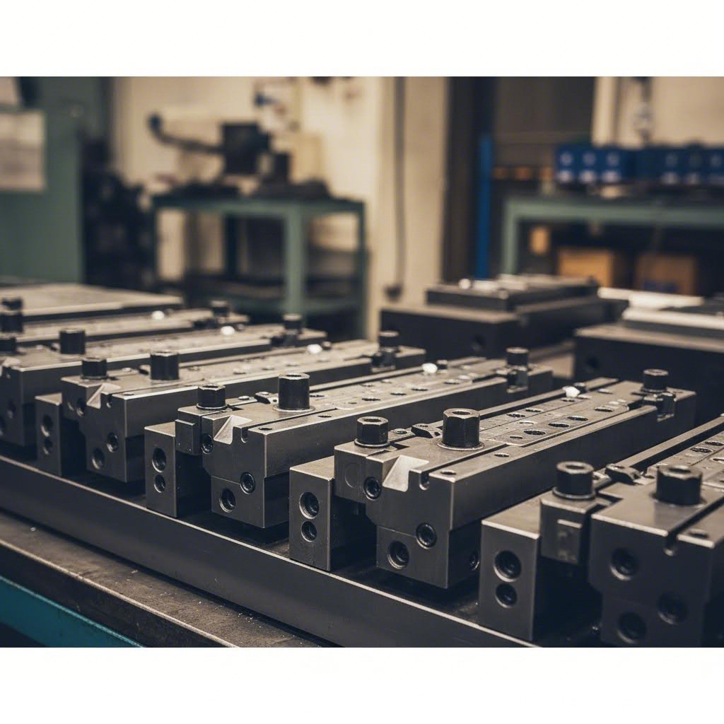
Leikkausmuotti koostuu useista kriittisistä elementeistä, joista jokainen on suunniteltu suorittamaan tiettyjä tehtäviä:
- Muottipohja (ylä- ja alapuoli) — Rakennerakenne, joka ylläpitää tarkkaa kohdistusta kaikkien komponenttien välillä. Tarkasti hionnalla valmistetut pinnat varmistavat suoransuuntaisuuden, joka vaikuttaa suoraan osien mittojen tarkkuuteen.
- Punch — Mieskomponentti, joka kohdistaa voiman muovaamaan tai leikkaamaan materiaalia. Työkalun geometria, materiaalivalinta ja pintakäsittely määräävät leikkausterän kestävyyden ja osan laadun.
- Muottinuppi (tai vaihtonuppi) — Naiskomponentti, joka ottaa työkalun vastaan. Välys työkalun ja muottinupin välillä — tyypillisesti 5–10 % materiaalin paksuudesta kummallakin puolella leikkaustoimintoja varten — vaikuttaa suoraan reunojen laatuun ja karvojen muodostumiseen.
- Irrotuslevy — Pitää materiaalin tasaisena muovauksen aikana ja irrottaa työkappaleen työkalusta paluuliikkeessä. Jousipaineen on oltava tasapainossa riittävän pitopaineen ja materiaalivaurioiden välttämisen välillä.
- Ohjausnahoilla ja sukuloinseilla — Ylläpitävät tarkan kohdistuksen ylemmän ja alemman muottipuoliskon välillä miljoonien syklien ajan. Kuluneet ohjaimet aiheuttavat epäkohdistumista, joka tuottaa toleranssien ulkopuolella olevia osia.
- Piloteiksi — Aseta nauha tarkasti kuhunkin asemaan vaiheittaisissa muoteissa. Ohjaimen tarkkuus määrittää suoraan valmiiden osien ominaisuuksien keskinäiset suhteet.
U-Needin kattavan oppaan mukaan näiden komponenttien vuorovaikutus on mekaaninen baletti, joka on synkronoitu murto-osaksi sekuntia painokoneen syklin mukaan. Jokainen elementti on suunniteltava ja valmistettava tiukkojen standardien mukaisesti, sillä yhden elementin epäonnistuminen voi johtaa ongelmien ketjureaktioon.
Materiaalin valinta muottikomponenteille on kriittisen tärkeää. Työkaluteräkset, kuten D2, A2 ja S7, tarjoavat kovuuden ja kulumisvastuksen, jota tuotantopursotuskoneisto vaatii. Käyttökohteisiin, joissa esiintyy runsasta kulumista, karbidilisät pitkittävät työkalun käyttöikää huomattavasti – vaikkakin korkeammalla alkuperäisellä hinnalla. Teräksen ja karbidin valinta perustuu usein tuotantomäärään: karbidi on taloudellisesti kannattava, kun sen pidentynyt käyttöikä kompensoi sen korkeamman hinnan sadattuhannissa tai miljoonissa syklin kuluessa.
Työkalujen kehitys: konseptista tuotantoon
Kuinka osan suunnittelu muuttuu tuotantoon valmiiksi työkaluksi? Tämä prosessi sisältää useita vaiheita, joista jokainen perustuu edelliseen, jotta riskit vähenevät ja tuotantoon siirtymisaika lyhenee.
Osan piirustusanalyysi tulee ensin. Ennen kuin mitään muottisuunnittelua aloitetaan, insinöörit arvioivat, onko leikkaus edes oikea prosessi kyseiselle osalle. He tarkastelevat materiaalimäärittelyjä, vaadittuja toleransseja, geometrista monimutkaisuutta ja odotettuja volyymejä. Tämä toteutettavuuden arviointi estää myöhempänä kehityksessä ilmenevät kalliit yllätykset.
Nauhan asettelun suunnittelu seuraa edistyneille muoteille. Tämä keskeinen vaihe määrittää, miten materiaali liikkuu muotin läpi — mitkä toiminnot tapahtuvat missäkin asemassa, kuinka paljon nauhaa etenee jokaisella iskulla sekä missä kantavat verkot ja ohjaimet sijaitsevat. Kuten U-Need selittää, nauhan asettelu on edistyneen muotin henki. Hyvin suunniteltu asettelu minimoi materiaalinhukkaa samalla kun maksimoi tuotantonopeuden.
3D-mallinnus ja 2D-yksityiskohtien laatiminen käsitteellinen asettelun muuntaminen valmistettaviksi komponenteiksi. Nykyaikaiset CAD-järjestelmät mahdollistavat suunnittelijoiden komponenttien vuorovaikutuksen visualisoinnin, etäisyyksien tarkistamisen ja mahdollisten törmäysten tunnistamisen ennen kuin mitään metallia leikataan. Jokainen vaanu, die-nappi, irrotuslevy ja ohjauskomponentti saa yksityiskohtaiset piirustukset, jotka määrittelevät mitat, toleranssit, materiaalit ja lämpökäsittelyvaatimukset.
Muotin laadun ja osien johdonmukaisuuden välistä suhdetta ei voida liioitella. Metalliosien valmistukseen tarkoitettu metallin painopuristuskone voi tuottaa vain niin tarkkoja osia kuin sen työkalut sallivat. Jos muotin komponenteissa esiintyy mitallista vaihtelua, valmiit osat heijastavat tätä vaihtelua – kerrottuna jokaisella puristussyklillä.
Miten tekninen erinomaisuus vähentää markkinoille pääsyn aikaa
Tässä nykyaikainen teknologia muuttaa perinteistä työkalujen kehitystä. Tietokoneavusteinen suunnittelu (CAE) ja elementtimenetelmä (FEA) -ohjelmistot mahdollistavat koko painoprosessin simuloinnin digitaalisesti ennen kuin yhtään teräspalaa on leikattu.
Mitä simulointi voi ennustaa? Mukaan Keysightin analyysiin , levymetallin muovaussimulointi ratkaisee useita merkittäviä haasteita:
- Jousivaikutuksen ennustaminen — Korkean lujuuden teräkset ja alumiiniseokset osoittavat merkittävää kimmoista palautumista, mikä tekee mittojen tarkkuudesta jatkuvan haasteen. Simulointi ennustaa nämä vaikutukset ennen kuin työkalut valmistetaan.
- Rypistymis- ja repeämisanalyysi — Virtuaalikokeet tunnistavat, missä materiaali rypistyy puristuksen seurauksena tai repeää liiallisen venymisen vuoksi – mahdollistaen muottigeometrian muutokset ennen fyysistä testausta.
- Levynpidikkeen voiman optimointi — Simulointi määrittää optimaaliset pressiasetukset, vähentäen aikaa vievää perinteistä fyysistä testausta.
- Materiaalin virtausvisualisointi — Insinöörit voivat tarkasti seurata, miten metalli liikkuu muovauksen aikana, ja tunnistaa mahdollisia ongelmia, jotka jäävät huomaamatta jopa kokeneiltakaan työkalumiehiltä.
Liiketoimintavaikutukset ovat merkittävät. Virtuaalinen validointi mahdollistaa nopean iteraation ja hionnan – digitaalisen mallin muuttaminen on paljon edullisempaa ja nopeampaa kuin kovan työkaluteräksen uudelleen koneuttaminen. Tämä simulointivaihe vähentää hankkeiden riskejä, lyhentää fyysisiä koekäyttöjaksoja ja lisää huomattavasti ensimmäisen kerran onnistumisen todennäköisyyttä.
Vaativiin sovelluksiin, kuten automaalisvalmisteisiin, tarkkuuslyöntimuottiratkaisut IATF 16949 -sertifioidulla ja CAE-simulointikyvyllä tarjoavat virheettömät tulokset, joita OEM-standardit edellyttävät. Jotkut edistyneet toimittajat tarjoavat nyt nopeaa prototyyppivalmistusta jo 5 päivässä korkealla ensimmäisen kerran hyväksymisasteella yli 93 % – mittareilla mitataan tekniikan erinomaisuutta metallilyöntilaitteissa ja työkaluissa. Valmistajille, jotka vaativat kattavia muottisuunnittelun ja valmistuksen kykyjä, resurssit kuten Shaoyin autoteollisuuden leikkuumuottiratkaisut näyttävät, mitä edistynyt muottitekniikka pystyy saavuttamaan.
Oikeaan muottisuunnitteluun ja kehitykseen tehty investointi tuottaa tulosta koko sinun leikattujen komponenttien tuotannon eliniän ajan. Hyvin suunniteltu muotti tuottaa johdonmukaisia osia vuorosta toiseen, vuodesta vuoteen – kun taas heikompi suunnittelu aiheuttaa jatkuvia laatuongelmia ja tuotantokatkoksia.
Mutta vaikka parhaat die-suunnittelut vaativat tehokasta laadunvalvontaa suorituskyvyn ylläpitämiseksi. Seuraavassa osiossa tarkastellaan tarkastusmenetelmiä ja vikojen ehkäisystrategioita, jotka pitävät leikkaustoiminnan sujuvana.
Laadunvalvonta ja vikojen ehkäisy leikkauksessa
Muotteesi on suunniteltu täydellisyyteen. Puristimesi toimii optimaalisilla asetuksilla. Silti leikatut osat jäävät joskus teknisten määritysten ulkopuolelle. Mikä meni pieleen?
Tässä on totuus, jonka useimmat valmistajat huomaavat liian myöhään: laadunvalvonta ei ole jotain, mitä lisätään tuotannon loppuun – se on integroitu järjestelmä, joka havaitsee ongelmat ennen kuin ne muuttuvat kalliiksi romuksi. Tarkastusmenetelmien ja vikojen juurisyytjen ymmärtäminen muuttaa toimintatapaasi reagoivasta ennaltaehkäiseväksi.
Tarkastellaan kattavaa laatukehystä, joka pitää tarkkuusleikkausosat sallituissa toleransseissa ja asiakkaasi tyytyväisinä.
Tarkastusmenetelmät, jotka havaitsevat virheet varhain
Tehokas laadunvalvonta alkaa siitä, että tarkastusmenetelmät vastaavat tarkasti määriteltyjä vaatimuksia. Erilaiset leikatut osat edellyttävät erilaisia varmistustapoja, ja oikea valinta tasapainottaa perusteellisuuden ja tuotannon tehokkuuden.
Koordinaatiomittareita (CMM) ovat mittojen tarkistamisen kultainen standardi leikatuille metalliosille. Mukaan SSF Washers , nämä kehittyneet laitteet käyttävät tarkkuuskohtia kolmiulotteisten mittojen keräämiseen mikrometrin tarkkuudella. CMM-testaus mahdollistaa kattavan geometrisen analyysin, johon kuuluu esimerkiksi tasomaisuus, kohtisuoruus, keskisymmetrisyys ja profiilipoikkeamat, joita manuaaliset mittausvälineet eivät pysty luotettavasti havaitsemaan.
Mittausprosessi edellyttää asianmukaista työkappaleen kiinnitystä liikkeen eliminoimiseksi skannauksen aikana. Tekniset asiantuntijat määrittävät referenssitiedot teknisistä piirustuksista ja tarkkailevat systemaattisesti kriittisiä ominaisuuksia etukäteen määriteltyjen tarkastussuunnitelmien mukaisesti. Edistynyt ohjelmisto luo yksityiskohtaisia raportteja, jotka vertaavat todellisia mittauksia CAD-määrityksiin, mikä mahdollistaa nopean tunnistamisen mitallisista poikkeamista.
GO/NO-GO-mittarit tarjoavat nopean tuotantolattian vahvistuksen suurille toiminnoille, joissa CMM-testaus aiheuttaisi pullonkauloja. Nämä erityiset kiinnityslaitteet sisältävät kriittiset mitalliset rajat fyysisinä rajoitteina, jolloin operaattorit voivat nopeasti varmistaa osien noudattamista ilman erikoistunutta mittauskoulutusta. Oikein suunniteltu mittausjärjestelmä tarkistaa useita ominaisuuksia samanaikaisesti samalla kun se pitää tarkastussyklin kestot yhteensopivina tuotannonopeuksien kanssa.
Pinnan laadun arviointi täyttää sekä toiminnalliset että esteettiset vaatimukset. Profilometrilaitteet mittaavat pinnankarkeusparametreja, kuten Ra-, Rz- ja Rmax-arvoja, kansainvälisten standardien mukaisesti. Leikatuille levyosille, joissa vaaditaan tarkkaa istuvuutta tai tiiviyspintoja, pinnanlaadun varmistaminen on olennaisen tärkeää.
Materiaalin testaus varmistaa, että saapuva materiaali täyttää tekniset vaatimukset ennen tuotannon aloittamista. Kovuustesti, jossa käytetään Rockwell-, Brinell- tai Vickers-menetelmiä, antaa tietoa materiaalisten ominaisuuksien vaikutuksesta leikattujen terösosien suorituskykyyn. Metallografinen tutkimus paljastaa materiaalin sisäisen rakenteen – raekoon, epäpuhtauksien jakautumisen ja vaihetunnistuksen – ja tukee materiaalimääritysten noudattamista.
Tilastollinen prosessien hallinta (SPC) muuntaa yksittäiset mittaukset käyttökelpoiseksi tietotuotteeksi. Tarkkailukaaviot seuraavat sekä prosessin keskittymistä että vaihtelua, kun taas kyvykkyysindeksit (Cp, Cpk) mittaavat prosessin suorituskykyä spesifikaatiovaatimuksiin nähden. Reaaliaikainen tiedonkeruu mahdollistaa virheellisten tilanteiden välittömän havaitsemisen ennen kuin virheellisiä osia päätyy asiakkaille.
Yleisiä leikkausvirheitä ja niiden juurisyyt
Vaikka hyvin suunnitellut prosessit tuottavatkin silloin tällöin virheitä, ongelman syyn ymmärtäminen – ei ainoastaan sen oireiden tunnistaminen – mahdollistaa kohdistettujen ratkaisujen kehittämisen turhauttavan kokeilun sijaan.
- Karkauma — Muodon ja mittojen poikkeama, joka ilmenee leikatun osan irrottaessa muotista. Tämä johtuu siitä, että materiaali palautuu osittain kimmoisesti muovauksen jälkeen. Koska Jeelix selittää , kimmoisa takaisinmeno aiheuttaa jatkuvia haasteita, kun käsitellään kehittyneitä korkean lujuuden teräksiä (AHSS) ja alumiiniseoksia, mikä vaikuttaa suoraan lopullisen kokoonpanon tarkkuuteen. Ongelman juurisyyniin kuuluvat riittämätön ylikääntökorjaus, riittämätön korauspaine sekä materiaaliominaisuuksien vaihtelut eri erien välillä.
- Rei'ittyminen ja halkeilu — Tapahtuu, kun paikallinen vetovoima muovauksen aikana ylittää materiaalin muovattavuuden rajan. Tämä kriittinen vika tekee osista heti kelvottomia. Juurisyyniin kuuluvat liiallinen vetosyvyys riittämättömän voitelun kanssa, riittämättömät muottikaaret, jotka keskittävät jännityksen, epäasianmukainen levytyön pitimen voima, joka rajoittaa materiaalin virtausta, sekä materiaali, joka ei täytä ductility-määrittelyjä.
- Rumputumiseen — Aaltojen kaltaiset rypleet muodostuvat lieviin tai seinämäalueisiin, kun puristusjännityksen alainen materiaali kiristyy ja pinotaan. Syvieveivossa lievi kokee jatkuvasti pienenevän kehän, kun se virtaa sisäänpäin, mikä luo tangentiaalisen puristusjännityksen. Kun tämä jännitys ylittää materiaalin kiristymisvastuksen, muodostuvat rypyt. Juurisyyt ovat riittämätön liuskapidikkeen voima, liiallinen materiaali lievialueella sekä virheellinen vetonauhan konfiguraatio.
- Kiillot — Terävät reunat tai kohonneet materiaalit, jotka jäävät leikkuutoimintojen jälkeen. Liiallinen työkaluvälys on pääasiallinen syy—kun välys ylittää optimaaliset arvot (yleensä 5–10 % materiaalin paksuudesta kummallakin puolella), materiaali murtuu epätasaisesti eikä leikkaudu siististi. Kuluneet leikkuureunat, virheellinen työkalujärjestys ja virheellinen nuppityökalun ja kuoppatyökalun ajoitus vaikuttavat myös.
- Mittatarkkuuden heikkeneminen — Osat eivät osu tarkkuusvaatimusten mukaisiin toleransseihin, vaikka muottigeometria näyttää oikealta. Juurisyyt kuuluvat lämpölaajenemiseen pitkien tuotantokäyrien aikana, muotin kulumiseen, joka vaikuttaa kriittisiin ominaisuuksiin, materiaalin paksuusvaihteluihin ja paineen taipumiseen kuormitettaessa.
- Kuluminen ja naarmutus — Pintavauriot johtuvat materiaalin siirtymisestä levy- ja muottipintojen välillä. Jeelixin mukaan kuluminen liittyy kylmähitsaukseen, jossa pieniä levymateriaalin hiukkasia kiinnittyy muottipintaan – usein syynä pintalaadun asteittaiseen heikkenemiseen. Riittämätön voitelu, yhteensopimattomat muottipinnankäsittelyt ja liiallinen muovauspaine edistävät kulumista.
Esinäisten laadun varmistamiseksi suunnitellut ennaltaehkäisystrategiat
Välittömien ongelmien ratkaiseminen voittaa yksittäisiä taisteluja. Laadunvarmuuden takaavien järjestelmien rakentaminen voittaa sodan. Nämä strategiat kohdistuvat ongelmien juurisyihin, ei oireisiin.
Kimpoamisen hallintaan:
- Suunnittele muotit ylivientikorjauksella, joka perustuu simulointien ennusteisiin
- Käytä rullaimuunnosta kriittisiin taitekohtiin saavuttaaksesi materiaalin myötölujuuden yli koko paksuuden
- Ota huomioon vaihtelevat liuskapidikkeen voimaprofiilit muovausiskun aikana
- Toteuta materiaaliominaisuuksien varmistus eri erien välisiin vaihteluihin varautumiseksi ennen tuotantoa
Puristumisen ja halkeamisen estämiseksi:
- Optimoi työkalujen kaarevuussäteet jakaaksesi jännitys kuormaa suuremmille kosketuspaloille
- Käytä muovaus simulointia tunnistaaksesi korkean venymän alueet ennen työkalujen valmistusta
- Varmista voitelun tasaisuus—riittämätön voitelu lisää murtumariskiä huomattavasti
- Harkitse useita vetoperäytysvaiheita välillä olevalla hehkutuksella syvästi muovattuihin metallipainokomponentteihin
Rypytysongelmien poistamiseksi:
- Säädä liuskapidikkeen voimaa tarjoamaan riittävä vastustus ilman materiaalivirran rajoittamista
- Suunnittele muottipesän muotoiset nauhat, jotka ohjaavat materiaalin virtausta muottikuppiin
- Optimoi leikkuukappaleen koko vähentääksesi ylimääräistä materiaalia, joka vaatii puristusta
- Varmista, että paineen työntöjärjestelmä tuottaa tasaisen ja yhtenäisen paineen
Piilopursien vähentämiseksi:
- Pitäkää muotin välys tarkastamalla ja säätämällä säännöllisesti määritellyn toleranssin sisällä
- Toteuttakaa terävöityssuunnitelmat iskumäärän perusteella älkääkä odottakoon laatuvikailmoituksia
- Tarkistakaa muotin asento jokaisessa asennuksessa – pienikin epäkeskisyys keskittää kulumisen ja edistää piilopursien syntymistä
- Harkitkaa muotin materiaaleja ja pinnoitteita, jotka sopivat tuotantomäärälle ja käytetylle materiaalityypille
Mittatarkkuuden ylläpitämiseksi:
- Toteuttakaa lämpötilakorjaus, kun ympäristön olosuhteet vaihtelevat
- Seuraa prosessin trendejä SPC:n avulla tunnistaaksesi asteittaisen poikkeaman ennen kuin toleranssit ylittyvät
- Luo saapuvan materiaalin tarkastusmenettelyt, jotka varmentavat paksuuden ja ominaisuudet
- Dokumentoi ja standardoi asennusmenettelyt eliminoidaksesi vaihtelun operaattorien välillä
Laatu syvämuovauksessa saavutetaan tarkastuksilla vain – se on rakennettu jokaiseen prosessisuunnittelun, työkalujen kehityksen ja tuotannon ohjauksen osa-alueeseen
Tehokkaimmat laadunohjelmat yhdistävät useita lähestymistapoja: saapuvan materiaalin varmistus estää ongelmat ennen niiden alkamista, prosessin aikainen valvonta havaitsee poikkeamat ennen kuin toleranssirajat ylittyvät, ja lopputarkastus takaa, että vain vaatimukset täyttävät metallisia syvämuovatut osat päätyvät asiakkaille
Toleranssien huomioonottaminen tulisi ohjata koko tarkastusstrategiaasi. Tiukemmat toleranssit edellyttävät ankarampia mittausmenetelmiä, tiheämpää tarkastusta ja kehittyneempiä prosessikontrolleja. Osan, jolle vaaditaan ±0,001 tuuman toleransseja, tarkkuus on varmistettava CMM-laitteella ja SPC-rajojen on oltava tiukat, kun taas kiinnikkeelle, jolle sallitaan ±0,030 tuumaa, saattaa riittää ajoittainen mittauspäällikön tarkastus.
Kun tehokkaat laatuohjaukset on asennettu, leikkaustoimintasi voi jatkuvasti täyttää erilaisten teollisuudenalojen vaativat vaatimukset – joilla kullekin on omat määrityksensä ja sertifiointitarpeensa.
Teollisuuden sovellukset ja erityisvaatimukset
Leikkaustoimintasi tuottaa virheettömiä osia tiukilla toleransseilla ja tasaisella laadulla. Mutta tässä kysymys, joka määrittää täyttävätkö osat todella asiakastarpeet: täyttävätkö ne alakohtaiset vaatimukset?
Eri teollisuudenalat asettavat täysin erilaisia vaatimuksia metallistampauskomponenteille. Viihdeajoneuvoon tarkoitettu kiinnike kohtaa täysin erilaisia rasituksia, sertifiointivaatimuksia ja laatuvaatimuksia kuin ulkoisesti samannäköinen kiinnike, joka on asennettu lentokoneeseen. Näiden erojen ymmärtäminen auttaa oikean toimittajan valinnassa, sopivien materiaalien määrittelyssä ja kalliiden yhteensopivuusongelmien välttämisessä.
Tarkastellaan, kuinka suuret teollisuudenalat muokkaavat stampausvaatimuksia – ja mitä nämä erot tarkoittavat projektillesi.
Autoteollisuuden stampausvaatimukset ja standardit
Autoteollisuuden metallistampaus edustaa yhtä vaativimmista sovelluksista teollisuuden stampauksessa. Jokainen ajoneuvossa oleva metallistampattu osa täytyy täyttää tiukat suorituskyky-, turvallisuus- ja laatuvaatimukset samalla kun se pysyy kuluttajahintojen asettamissa kustannusrajoissa.
Mikä tekee autoteollisuuden stampinguista ainutlaatuisen? Määrät, johdonmukaisuus ja jäljitettävyysvaatimukset kohtaavat tasolla, jota harvat muut teollisuudenalat saavuttavat. Xometryn sertifiointikatsauksen mukaan International Automotive Task Force (IATF) ylläpitää kehyksiä käyttäen ISO 9001 -laatujohtamisjärjestelmää varmistaakseen johdonmukaisen laadun koko maailman autoteollisuuden toimitusketjussa.
IATF 16949 -sertifiointi on muodostunut de facto -vaatimukseksi autoteollisuuden toimittajille. Tämä standardi menee peruslaatujohtamisen lisäksi osoittaen:
- Tuotteen turvallisuus —Dokumentoidut prosessit, jotka varmistavat turvallisuuskriittisten komponenttien täyttävän vaatimukset joka kerta
- Puutteiden ehkäisy —Järjestelmälliset lähestymistavat laatuongelmien poistamiseksi ennen kuin ne päätyvät kokoonpanolinjalle
- Muunnelmien vähentäminen —Tilastolliset menetelmät, jotka hallitsevat prosessimuunnelmia miljoonien tuotantokierrosten ajan
- Toimitusketjun hallinta —Vaateiden eteneminen useiden toimittajatasojen läpi
Tarkkavälineinen metallin leikkaus autoteollisuuden sovelluksiin käsittää yleensä runkopaneelit, rakenteelliset kiinnikkeet, alustakomponentit, istuinterungot ja voimanvälityselementit. Materiaalit vaihtelevat mietosta teräksestä sisäosien kiinnikkeisiin kehittyneisiin korkean lujuuden teräksiin ja leikattuun alumiiniin painon kannalta kriittisiä runkorakenteita varten.
Valmistajille, jotka suuntaavat tuotantoaan autoteollisuuteen, OEM-standardien mukainen työkaluvälineistö ja IATF 16949 -sertifiointi muodostavat perustan näiden vaativien vaatimusten täyttämiseksi. Insinööripalvelut, jotka tarjoavat kustannustehokkaita, korkealaatuisia ratkaisuja tiettyjen OEM-standardien mukaisesti – kuten Shaoyin autoteollisuuden leikkuumuottiratkaisut — osoittavat kyvyt, joita tämä toimiala edellyttää.
Elektroniikan ja lääketieteen laitteiden tarkkuusvaatimukset
Kuvittele liittimen koskettimen leikkaaminen ohuempaa kuin ihmisen karva, jossa toleranssit mitataan mikrometreissä. Tämä on elektroniikkateollisuuden leikkauksen todellisuus – missä miniatyrisointi ajaa entistä tiukempia tarkkuusvaatimuksia.
Elektroniikkateollisuus käyttää tarkkavälineistä metallin leikkausta komponenttien valmistukseen, kuten:
- Yhdistimet ja terminaali —Yhteyspinnat, joissa tarvitaan tarkkaa geometriaa luotettavien sähköliitosten varmistamiseksi
- EMI/RFI-suojaus —Kotelot, jotka suojaa herkkiä piirejä sähkömagneettiselta häiriöltä
- Johtokehykset —Tarkkuuskantajat puolijohdepakkaamiseen
- Akun kosketukset —Johdintarvikkeet, joissa vaaditaan tasainen jousivoima ja pinnankäsittely
Sähkömekaanisten osien leikkaus yhdistää sähköiset ja mekaaniset vaatimukset—osien on ohjattava virta luotettavasti samalla kun ne kestävät mekaanista rasitusta toistuvista asennusjaksoista tai lämpölaajenemisesta.
Lääkintälaitteiden leikkaustyöt edellyttävät samanlaista tarkkuutta kuin elektroniikka, mutta siihen liittyy lisäksi biologinen yhteensopivuus ja säädösten noudattaminen. LSRPF:n teollisuuskatsaus kertoo, että metallileikkaukset ovat laajalti käytössä kirurgisissa instrumenteissa, diagnostiikassa ja hoitolaitteissa, ja niissä täytetään tiukat laatu- ja turvallisuusvaatimukset korkean tarkkuuden, korkean lujuuden ja korroosionkestävyyden ominaisuuksien avulla.
Lääketieteelliset sovellukset edellyttävät:
- Materiaalin jäljitettävyys —Täydellinen dokumentaatio raaka-aineesta valmiiseen komponenttiin
- Validoidut prosessit —Käytännössä testatut valmistusmenetelmät, jotka tuottavat johdonmukaisia tuloksia
- Puhtaat valmistusympäristöt —Saatujen käyttötarkoituksiin sopiva saastumisen hallinta
- Sääntelyjen noudattaminen —FDA-rekisteröinti ja ISO 13485 -laadunhallintasertifiointi
Ilmailu ja puolustus: Kun epäonnistuminen ei ole vaihtoehto
Tässä ajatuskoe, joka havainnollistaa, kuinka toimialakohtaiset vaatimukset muokkaavat metalliosien leikkaamista: vertaa puristettua kiinniketta, joka on asennettu vapaa-ajoneuvoon, ja vastaavaa kiinnikettä, joka on asennettu kaupalliseen lentokoneeseen.
Molemmat kiinnikkeet voivat näyttää samanlaisilta. Molemmat voivat käyttää alumiiniseosta. Mutta ilmailukiinnikkeellä on vaatimuksia, joita vapaa-ajoneuvokiinnike ei koskaan kohtaa:
- Materiaalin sertifiointi —Ilmailuteollisuus edellyttää valssauskohtaisia testiraportteja, jotka dokumentoivat tarkan kemian ja mekaaniset ominaisuudet jokaiselle materiaalierälle
- Prosessin pätevöinti —Jokainen valmistusvaihe on hyväksyttävä ja lukittava; kaikki muutokset edellyttävät uudelleenhyväksyntää
- Ei-rakenteellinen testaus —Röntgen, väripenetraatio tai muut epätuhoavat testausmenetelmät varmentavat sisäisen eheyden
- Ensimmäisen esimerkin tarkastus —Kattava mitallinen tarkistus ennen tuotantoon laskemista
- Sarjan jäljitys —Jokainen osa on jäljitettävissä tiettyihin materiaalieriihin, operaatoreihin ja valmistuspäivämääriin
RV-kiinnike? Sen on täytettävä perusmitalliset vaatimukset ja materiaalimääritykset – mutta ilman lentokoneissa vaadittavaa laajaa dokumentointia, testausta ja hyväksyntää. Tämä ero vaikuttaa suoraan kustannuksiin, toimitusaikoihin ja toimittajahyväksyntävaatimuksiin.
Sotilaallisissa ja puolustuskäytöissä lisätään vielä ylimääräisiä tasoja, kuten ITAR-yhteensopivuus vientivalvonnan alaisiin tuotteisiin, MIL-SPEC-materiaali- ja prosessivaatimukset sekä turvallisuuspuhumukset luokitelluille ohjelmaille.
Kuluttajatuotteet ja rakennustuotteet
Kaikkiin leikattuihin komponentteihin ei tarvita lentokonealaan verrattavaa kelpoisuutta. Kuluttajatuotteissa ja rakennussovelluksissa eri ominaisuudet ovat usein tärkeämpiä: kustannustehokkuus, esteettinen ulkonäkö ja suurten tuotemäärien johdonmukaisuus.
Kuluttajatuotteiden leikkaus kattaa monenlaisia sovelluksia:
- Kotitalouslaitteiden komponentit —Pesukoneiden rummut, jääkaappipaneelit, ilmanvaihdon kiinnikkeet
- Keittiötuotteet —Ruuanlaittovälineet, astiat, elintarvikkeiden käsittelylaitteet
- Laitteisto —Saranat, lukot, laatikonsuljekkeet, kalusteosat
- Urheilutavarat —Laiterungot, suojakomponentit, lisävarusteet
Rakennus- ja rakennetekniikan leikkaustyöt keskittyvät rakenteellisiin komponentteihin, kuten katto-osaan, kehysten kiinnikkeisiin, sähköasentoihin ja arkkitehtonisiin koristeisiin. Näissä sovelluksissa käytetään yleensä sinkittyä tai päällystettyä terästä korroosion kestävyyden vuoksi altistetuissa olosuhteissa.
Miten toimialojen vaatimukset muokkaavat prosessivalintoja
Teollisuuden alojen väliset erot ovat tärkeitä ymmärtää, jotta voit tehdä perusteltuja päätöksiä toimittajista, prosesseista ja vaatimuksista. Seuraava vertailu korostaa, kuinka vaatimukset vaihtelevat eri suurissa toimialoissa:
| Teollisuus | Tyypilliset materiaalit | Toleranssivaatimukset | Määräominaisuudet | Sertifiointivaatimukset |
|---|---|---|---|---|
| Autoteollisuus | Korkean lujuuden alumiinipitoisen teräksen (HSLA), alumiinin ja ruostumattoman teräksen käyttö | ±0,002" - ±0,010" tyypillinen | Suuri tuotantomäärä; yli 100 000 kappaletta vuodessa on yleistä | IATF 16949 -sertifiointi vaaditaan; PPAP-dokumentaatio vaaditaan |
| Elektroniikka | Kupari, messinki, fosforivalkopronssi ja nikkeli-seokset | ±0,001 tuumaa tai tarkempi toleranssi; mikrotasoinen tarkkuus liittimille | Erittäin suuri tuotantomäärä; miljoonia kappaleita | ISO 9001 -sertifiointi; alaerityisiä sertifikaatteja (esim. IPC piirikortteja varten) |
| Lääketieteelliset laitteet | Ruostumaton teräs (316L), titaani ja erikoisseokset | ±0,001" - ±0,005"; sovelluksesta riippuen | Alhainen tai keskitasoeräkoko; suuri sekoitus | ISO 13485; FDA-rekisteröinti; materiaalien jäljitettävyys |
| Ilmailu | Alumiini (2024, 7075), titaani, Inconel | ±0,001" - ±0,003"; kriittisemmissä ominaisuuksissa tiukemmat toleranssit | Alhainen tai keskitasoeräkoko; pitkä ohjelman kesto | AS9100; NADCAP; asiakasspesifiset hyväksynnät |
| Kuluttaja/Kotitalouslaite | Hiiliteräs, sinkitty teräs, alumiini | ±0,005" - ±0,015" tyypillinen | Suuri määrä; kustannusherkkä | ISO 9001; UL/CSA sähkölaitteille |
| Rakenne | Sinkkipinnoitettu teräs, ruostumaton teräs, alumiini | tyypillisesti ±0,010"–±0,030" | Suuri määrä; kausivaihtelut kysynnässä | Rakentamismääräysten noudattaminen; ASTM-standardit |
Mitä tämä vertailu paljastaa? Useita keskeisiä havaintoja nousee esille:
Sertifiointivaatimukset vaikuttavat suoraan toimittajan valintaan. Autoteollisuuden ohjelma edellyttää IATF 16949 -sertifioituja toimittajia – eikä muuta. Lääkintälaitteet vaativat ISO 13485 -yhteensopivuutta. Ilmailualalla tarvitaan AS9100-sertifiointia ja usein NADCAP-erikoisprosessien akkreditointia. Toimittajan valitseminen ilman asianmukaisia sertifikaatteja tarkoittaa kelpoisuusprosessin aloittamista alusta alkaen.
Toleranssivaatimukset ohjaavat prosessi- ja työkaluratkaisuja. Elektroniikkaliittimet, jotka vaativat mikrometrin tarkkuutta, edellyttävät hiontaleikkauksen tai erikoisia edistyneitä muotteja poikkeuksellisella kulumisvastuksella. Rakennekiskot, jotka kestävät ±0,030 tuuman toleransseja, voivat käyttää yksinkertaisempia työkaluja nopeammalla kehityksellä ja alhaisemmalla hinnalla.
Määräominaisuudet vaikuttavat taloudellisiin kompromisseihin. Autoteollisuuden suuret määrät oikeuttavat kattavaan työkaluinvestointiin ja automaatioon. Lääkintälaitteiden alhaisemmat määrät ja korkeampi sekoitus suosivat usein joustavia valmistustapoja, jotka uhraavat syklin ajan asetustehokkuuden hyväksi.
Materiaalimääritykset vaihtelevat huomattavasti. Ilmailussa käytettävät alumiiniseokset, kuten 7075-T6, vaativat erilaista käsittelyä kuin kodinkoneissa käytettävä hellä teräs. Lääkintäluokan ruostumaton teräs edellyttää materiaalitodistuksia ja jäljitettävyyttä, joita kuluttajatuotteet harvoin vaativat.
Oikea leikkausyhtiö ymmärtää, että toimialan vaatimukset – eikä vain osan geometria – määrittävät projektin menestyksen.
Arvioidessasi toimittajia tietylle sovelluksellesi, vertaa heidän sertifikaattejaan, kykyjään ja kokemustaan alan vaatimuksiin. Toimittaja, joka on erinomainen suurten sarjojen autoteollisuuden tuotannossa, saattaa kamppailla pienten sarjojen lentokonealan kelpuutusvaatimusten kanssa – ja toisin päin. Paras metallistampattu osa on sellainen, joka täyttää paitsi mittojen mukaiset vaatimukset, myös kaikki sääntely-, dokumentointi- ja laatuvaatimukset, joita alasi edellyttää.
Perusteltujen stampauspäätösten tekeminen projektillesi
Olet nyt tutustunut kattavasti metallistampusalueeseen – kylmämuovauksen perusteista materiaalien valintaan, puristintyyppeihin, toimintoihin, menetelmiin, työkalujen kehitykseen, laadunvalvontaan ja alakohtaisiin vaatimuksiin. Mutta kuinka yhdistät kaiken tämän tiedon konkreettisiksi päätöksiksi juuri omalle projektillesi?
Ymmärtää, mitä leikattu metalli on ja kuinka prosessi toimii, on vasta alkua. Oikea haaste piilee oikean materiaali-, menetelmä- ja valmistusyhteistyökumppanien yhdistämisesä omiin erityistarpeisiin. Tiivistetään kaikki käytännönläheiseksi viitekehykseksi, jota voit soveltaa välittömästi.
Avaintekijät leikkauksen projektien onnistumiselle
Kaikkia leikkausprosessin vaiheita tarkastellessa nousee esiin useita keskeisiä näkökohtia, jotka erottavat onnistuneet hankkeet kalliista epäonnistumisista:
Onnistuneet leikkaushankkeet edellyttävät oikean prosessin, materiaalien ja työkalukumppanin yhdistämistä tiettyyn sovellustarpeeseen – eivätkä pakota suunnittelua sopimaan toimittajan olemassa oleviin kykyihin.
Materiaalin valinta määrää kaiken muun prosessin eteenpäin. Valitsemasi leikkolevy vaikuttaa siihen, mitkä prosessit ovat käytettävissä, mitkä toleranssit saavutetaan ja kuinka paljon työkalut maksavat. Alumiiniin perustuva leikkolevyprosessi toimii eri tavalla kuin ruostumattomaan teräkseen perustuva prosessi, vaikka tuotettaisiin täysin samanlaisia geometrioita. Määrittele materiaalit ensisijaisesti toiminnallisten vaatimusten perusteella ja varmista leikattavuus ennen kuin teet investointeja työkaluihin.
Tuotantomäärä määrittää taloudellisen kannattavuuden. Leikkolevy on erinomainen suurten sarjojen valmistukseen, jossa työkalukustannukset jakautuvat tuhansille tai miljoonille osille. Prototyyppierille tai lyhyille tuotantosarjoille vaihtoehtoiset menetelmät, kuten CNC-työstö tai laserleikkaus, voivat olla edullisempia yksittäiskappalekustannuksista huolimatta. Tunne tuotannon määräennusteesi ennen kuin valitset valmistustavan.
Toleranssivaatimukset ohjaavat menetelmän valintaa. Vakiometallin muovausoperaatiot saavuttavat tavallisesti ±0,005 tuuman toleranssit. Tiukemmat vaatimukset edellyttävät erikoistuneempia menetelmiä – hienoleikkausta reunojen laadun varmistamiseksi, kolmintaa mittojen tarkkuutta varten tai jälkikoneointia kriittisille ominaisuuksille. Liiallinen toleranssien tiukentaminen lisää kustannuksia, eikä se tuo mukanaan toiminnallista arvoa.
Laatuvaatimukset on sovitettava alakohtaisten vaatimusten kanssa. IATF 16949 -sertifioitu toimittaja täyttää autoteollisuuden vaatimukset, mutta voi olla liiallinen kuluttajatuotteisiin. Toisaalta AS9100-sertifiointia ilman oleva toimittaja ei voi toimittaa lentokonesovelluksiin riippumatta teknisestä osaamisesta. Yhdenmukaista toimittajan pätevyydet omaan sääntelyympäristöösi.
Seuraavat vaiheesi leikkauksen valintaprosessissa
Valmis etenemään leikkaushankkeessasi? Noudattamalla tätä päätöksenteon viitekehystä voit varmistaa, että olet huomioinut kaikki kriittiset tekijät:
- Määrittele toiminnalliset vaatimukset täysin. Dokumentoi materiaalien ominaisuudet, mitoitustoleranssit, pinnankarheusvaatimukset ja mahdolliset erityisvaatimukset (johtavuus, korroosionkesto, biologinen yhteensopivuus) ennen kuin otat yhteyttä toimittajiin. Puutteelliset spesifikaatiot johtavat virheellisiin tarjouksiin ja pettymyksiin.
- Määrittele realistiset määräennusteet. Sisällytä ensimmäisen vuoden määrät, elinkaaren aikaiset kokonaismäärät ja kysynnän vaihtelu. Nämä luvut vaikuttavat suoraan työkaluinvestointipäätöksiin ja toimittajien suositukseen edistyvän leikkuumuottien, fourslide- tai muiden vaihtoehtoisten menetelmien välillä.
- Tunnista sovellettavat teollisuusstandardit. Määritä, mitä sertifiointeja, dokumentaatiovaatimuksia ja laatuvaatimuksia sovelluksesi edellyttää. Tämä rajaa toimittajavaihtoehtojasi välittömästi ja estää turhan työn kelvottomien kumppaneiden arvioinnissa.
- Pyydä valmistettavuuden suunnittelua (DFM) koskevaa palautetta varhaisessa vaiheessa. Ota yhteyttä mahdollisiin toimittajiin ennen lopullisten suunnitelmien vahvistamista. Kokeneet leikkausinsinöörit tunnistavat usein geometrisia muutoksia, jotka vähentävät työkalujen monimutkaisuutta merkittävästi ja parantavat osien laatua toiminnallisuutta kompromisoimatta.
- Arvioi kokonaiskustannukset – ei ainoastaan kappalehinta. Ota huomioon työkaluinvestoinnit, kehitysaikataulu, laadun kustannukset, logistiikka ja toimittajan vakaus. Alimmalla tarjotulla kappalehinnalla on harvoin alin kokonaisprojektikustannus, kun kaikki tekijät otetaan huomioon.
- Suunnittele tuotannon validointi. Varaa aikaa ja budjetti ensimmäisen artikkelin tarkastukseen, prosessikelpoisuustutkimuksiin ja mahdollisiin alakohtaisiin hyväksymisvaatimuksiin. Näiden vaiheiden kiirehtiminen aiheuttaa laatuongelmia, jotka jatkuvat koko osien tuotannon elinkaaren ajan.
Lujitemuovauskehitys jatkuu servojauhojen edistymisen, simulointipohjaisen muottikehityksen ja yhä kehittyneempien laatuvarmistusjärjestelmien myötä. Perusperiaatteet kuitenkin säilyvät samoina: onnistuneisiin projekteihin kuuluu selkeät vaatimukset, prosessien sovittaminen näihin vaatimuksiin sekä toteutus pätevien kumppanien kanssa, joilla on aiheeseen liittyvää kokemusta.
Tuotitpa miljoonia autoteollisuuden kiinnikkeitä tai satoja erikoisia lentokoneiden komponentteja, lujitemuovauksen päätöksentekokehys pysyy samana. Määrittele mitä tarvitset. Ymmärrä mitä kukin menetelmä tarjoaa. Valitse kumppanit, joiden osaaminen vastaa vaatimuksiasi. Toteuta sen jälkeen tehtävä laatuvarmistusjärjestelmillä, joita alasi edellyttää.
Lujitemuovatut metalliosasi ovat vain niin hyviä kuin tuotannon aloittamista edeltävät päätökset. Käytä hankkimääsi tietoa viisaasti tekemiesi päätösten tueksi – ja muunna raakalevy täsmälleen sellaisiksi komponenteiksi kuin sovelluksesi vaatii.
Usein kysytyt kysymykset leikkausprosesseista
1. Säännöt Mitkä ovat leimausmenetelmän seitsemän vaihetta?
Seitsemän yleisintä metallin leikkausvaihetta ovat raakileleikkaus (työkappaleen erottaminen levyltä), rei'itys (reikien tekeminen), syvävetäminen (cupin- tai laatikkomuotojen muodostus), taivutus (kulmien luominen), ilmataivutus (ohjattu kulmanmuodostus), pohjautuminen ja kolhu (tarkkaa muovausta erittäin suurella paineella) sekä puristusleikkaus (ylimääräisen materiaalin poistaminen). Nämä toimenpiteet voidaan suorittaa peräkkäin etenevissä työkaluissa tai erillisinä prosesseina osan monimutkaisuuden ja määrävaatimusten mukaan.
2. Mitkä ovat eri leikkaustyypit?
Metallin muovaus käsittää useita eri menetelmiä: jatkuvan muovauksen suurten tuotantomäärien valmistukseen, jossa useat toiminnot suoritetaan peräkkäin, siirtomuovauksen suurille tai monimutkaisille osille, jotka vaativat syviä vetämisiä, nelisivun/monisivun muovauksen monimutkaisille pienille osille, joissa on monisuuntaisia taivutuksia, ja tarkka-arkinleikkuun tarkkuuskomponenteille, joissa vaaditaan sileitä reunoja. Jokainen menetelmä tarjoaa omat etunsa – jatkuvat muotit tarjoavat nopeutta, siirtomuotit selviytyvät monimutkaisuudesta, nelisivun muovaus tarjoaa joustavuutta pienemmille määrille ja tarkka-arkinleikkaus saavuttaa erinomaisen reunalaadun turvallisuuskriittisiin sovelluksiin.
3. Miten muovaus tehdään?
Leikkauksessa käytetään työkaluja ja suuripaineisia puristimia muuntamaan litteää levyä valmiiksi osiksi kylmämuovauksen avulla. Prosessi alkaa levyn syöttämisellä (kierukasta tai esileikattuina paloina) leikkuupuristimeen. Puristin kohdistaa voiman – usein satojen tonnien luokkaa – ajamalla nuppia kuviota vasten leikkaamaan, taivuttamaan tai muovaamaan metallia. Vaikka menetelmää kutsutaankin kylmämuovaamiseksi, leikkauksen aikana kitka synnyttää merkittävää lämpöä. Nykyaikaisissa toiminnoissa usein yhdistetään useita vaiheita yhteen työkalusarjaan, ja edistysleikkureilla suoritetaan leikkaus- ja muovausoperaatiot, kun materiaali etenee peräkkäisissä asemissa.
4. Mitkä materiaalit soveltuvat parhaiten metallin leikkaukseen?
Materiaalin valinta riippuu sovelluksen vaatimuksista. Hiiliteräs tarjoaa erinomaisen muovattavuuden ja edullisuuden kiinnikkeisiin ja rakennenosia. Rostumatonta terästä käytetään lääketieteellisissä ja elintarviketeollisuuden laitteissa korroosion kestävyyden vuoksi. Alumiini tarjoaa kevyt ominaisuudet lentokone- ja autoteollisuuden paneleihin. Kupari ja messinki soveltuvat erinomaisesti sähkösovelluksiin, joissa vaaditaan johtavuutta. Pinoamisominaisuuksiin vaikuttavia keskeisiä ominaisuuksia ovat muun muassa ductility (muodonmuutoksen kestävyys), vetolujuus, työkovettumisnopeus ja paksuus. IATF 16949 -sertifioinnin saaneet toimittajat, kuten Shaoyi, voivat neuvota materiaalin valinnassa tietyissä toleransseissa, tilavuuksissa ja sertifiointivaatimuksissa.
5. Miten valitsen vaiheittaisen ja siirtokuviomenetelmän välillä pinoamisessa?
Valitse vaiheittaistemppaaminen suurten tuotantomäärien (yli 10 000 vuodessa) valmistukseen pienistä keskikokoisista osista, joilla on kohtalainen monimutkaisuus – se tarjoaa nopeimmat sykliajat ja alhaisimmat kappalekustannukset. Valitse siirtotemppaaminen, kun osat ovat liian suuria vaiheittaisiin temppoihin, vaativat syviä vetämisiä tai tarvitsevat työstötoimenpiteitä työkappaleen molemmilta puolilta. Siirtotemput käsittelevät monimutkaisia kolmiulotteisia geometrioita, joita yhteydessä olevien nauhojen menetelmät eivät pysty tuottamaan. Ota huomioon työkaluinvestoinnit, tuotannon aikataulu ja odotetut määrät päätöstä tehdessä – vaiheittaiset temput maksavat enemmän alussa, mutta tuottavat parempia taloudellisia tuloksia suurella tuotantomäärällä.