 Pienet erät, korkeat standardit. Nopea prototyypinkehityspalvelumme tekee vahvistamisen nopeammaksi ja helpommaksi —

Metallintaittopalvelujen salaisuudet: 9 vikaa, jotka tuhoavat hankkeesi
Metallin taivutuspalvelun perusteiden ymmärtäminen
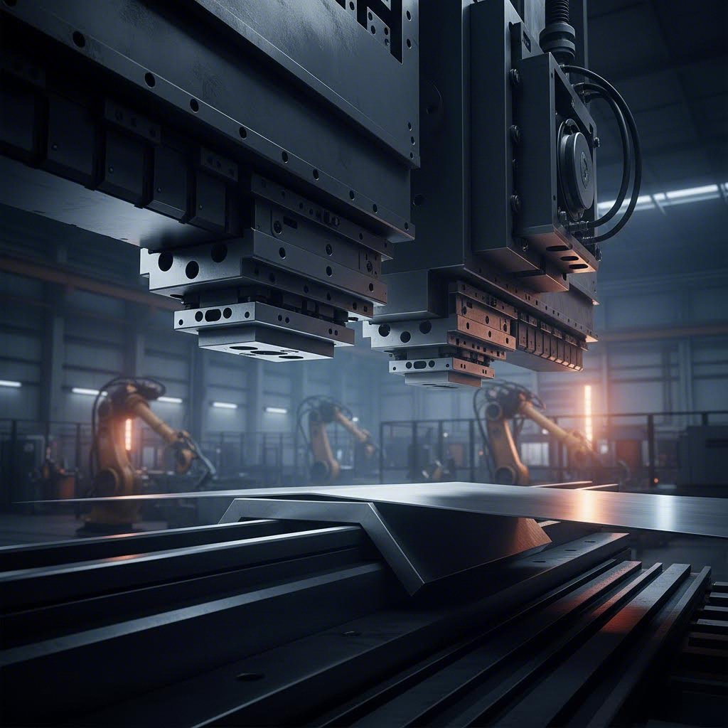
Oletko koskaan miettinyt, kuinka metallia taivutetaan rikkomatta sitä? Vastaus piilee tarkan tasapainon löytämisessä voiman, materiaaliominaisuuksien ja ohjatun muodonmuutoksen välillä. metallin kaarinta palvelu muuntaa litteää levy- tai plaattemateriaalia tarkasti soveltetulla paineella täsmällisiksi kulmikkaiksi muodoiksi – muuttaen raaka-aineen toiminnallisiksi komponenteiksi, jotka muodostavat lukemattomien teollisuudenalojen selkärangan.
Insinööreille, suunnittelijoille ja hankintaprofessionaaleille näiden perusteiden ymmärtäminen ei ole vain akateemista uteliaisuutta. Se on ero onnistuvien ensiyrityksessä olevien projektien ja niiden välillä, jotka kärsivät kalliista virheistä, viiveistä ja uudelleensuunnittelusta.
Mitä metallin taivutus todella tekee materiaalillesi
Kun voimaa kohdistetaan levyjen taivutustoimintoihin, tapahtuu jotain merkittävää molekyylitasolla. Materiaali muuttaa muotoaan pysyvästi plastisen muodonmuutoksen kautta – hallitun muunnoksen kautta, joka luo kulmat, kaaret ja monimutkaiset geometriat tasolevyistä.
Tässä on mitä todella tapahtuu:
- Taivutuksen ulkopinta kokee vetovoimia, joiden seurauksena se venyy ja pitenee
- Sisäpinta kokee puristusta, supistuen kun materiaalia työnnetään yhteen
- Neutraaliakseli —teoreettinen viiva materiaalin sisällä—ei veny eikä puristu tämän prosessin aikana
Tämä kaksinkertainen toiminta, jossa tapahtuu sekä venytystä että puristusta, on syy miksi metallin taivutus vaatii niin tarkkoja laskelmia. Jos tasapaino menee pieleen, kohtaat halkeamia ulkopinnalla tai rypleitä sisäpinnalla.
Miksi insinöörien tulee ymmärtää taivutuksen perusteet
Saatat ajatella: "Minä vain hankin osia – miksi tieteellinen puoli on tärkeää?" Ota huomioon tämä: alan asiantuntijoiden mukaan materiaalin valinta vaikuttaa suoraan komponenttien valmistettavuuteen, suorituskykyyn ja kustannustehokkuuteen. Kun ymmärrät taivutusta, voit:
- Määrittää sopivat taivutussäteet, jotka estävät materiaaliviat
- Valita materiaalit, jotka vastaavat suorituskykyvaatimuksiasi ja budjettiasi
- Ennustaa kimmoista paluuliikettä (springback) ja suunnitella siihen kompensoivia ominaisuuksia
- Viestintä tehostuu metallin taivutuspalveluntarjoajasi kanssa
- Vähentää prototyyppikierroksia ja nopeuttaa tuotantoon siirtymistä
Insinöörit, jotka hallitsevat nämä käsitteet, eivät vain saa tarjouksia – he saavat toimivia osia jo ensimmäisellä kerralla.
Ikään kuin muodonmuutoksen tiede
Metallin taivutus perustuu kriittiseen materiaaliominaisuuteen, jota kutsutaan taivutuslujuus —materiaalin kestävyyden mitta pysyvää muodonmuutosta vastaan. Kun sovellettu voima ylittää tämän kynnysarvon, metalli siirtyy kimmoisasta käyttäytymisestä (jossa se palautuisi alkuperäiseen muotoonsa) plastiseen käyttäytymiseen (jossa se säilyttää uuden muotonsa).
Kaksi keskeistä prosessia vaikuttavat siihen, miten materiaalit reagoivat taivutukseen:
- Virkistys: Metallin lämmittäminen tiettyyn lämpötilaan ja hidas jäähdyttäminen vähentävät kovuutta samalla kun lisäävät muovautuvuutta. Tämä tekee materiaalista helpommin muokattavan monimutkaisissa taivutuksissa.
- Kylmätyöskentely: Prosessit, kuten valssaus tai vasaraus, lisäävät teräksen kovuutta ja lujuutta, mutta tekevät siitä myös haurasta ja vaikeammin taivutettavaa.
Tämän suhteen ymmärtäminen materiaalien ominaisuuksien ja taivutustulosten välillä antaa sinulle mahdollisuuden tehdä parempia päätöksiä jo ennen tuotannon alkua. Materiaalisi jyväsuoja, sen pehmeysluokka sekä paksuus vaikuttavat kaikki siihen, muodostuuko osa onnistuneesti vai halkeako se painettaessa.
Seuraavissa osioissa tutustumme tarkkoihin taivutustekniikoihin, olennaiseen terminologiaan, materiaalivalintakriteereihin ja yleisiin virheisiin, jotka tuhoavat hankkeet – sekä tarkkaan siihen, miten niiltä vältetään.
Metallin taivutustekniikat selitettyinä
Nyt kun tiedät, mitä tapahtuu, kun metallia taivutetaan, seuraava kysymys kuuluu: miten valmistajat itse asiassa saavuttavat ne tarkat kulmat? Vastaus riippuu täysin valitusta menetelmästä – ja väärän menetelmän valinta voi merkitä eroa virheettömien osien ja kalliin romun välillä.
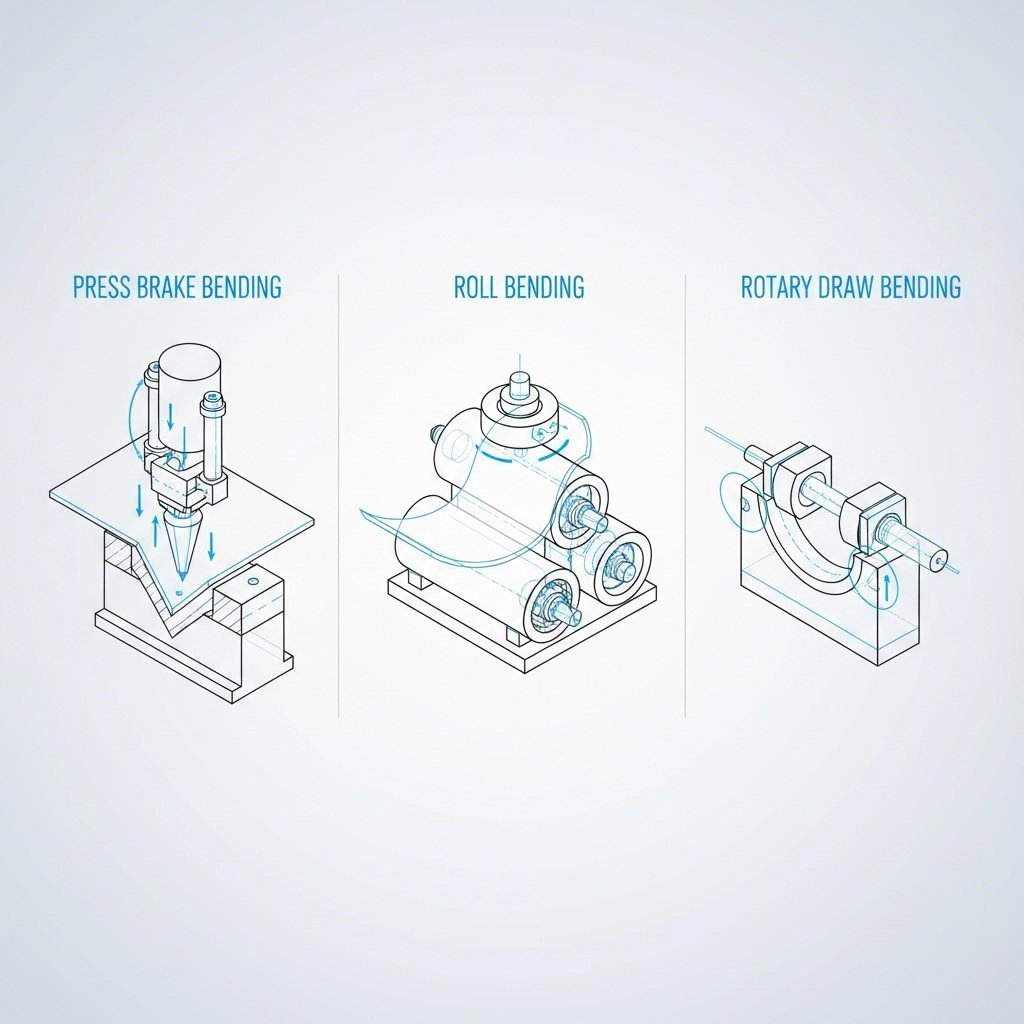
Jokainen taivutusmenetelmä perustuu erilaisiin mekaanisiin periaatteisiin, mikä tekee siitä sopivan tiettyihin sovelluksiin, materiaalipaksuuksiin ja geometrisiin vaatimuksiin. Käydään läpi kolme päämenetelmää, joita ammattimaiset metallin taivutuspalvelujen tarjoajat käyttävät jokapäiväisesti.
Puristusjyrsimen taivutus ja sen kolme vaihtoehtoa
Press brake -taivutus on edelleen levyjen taivutustoiminnon työhevonen . Tämäntyyppinen metallin taivutuskone käyttää vaippa- ja kuulakartiosysteemiä soveltaakseen voimaa ja luodakseen kulmikkaita taivutuksia levyihin. Kaikki puristusjarrujen toiminnot eivät kuitenkaan ole samanlaisia – on olemassa kolme erilaista vaihtoehtoa, joilla kullakin on yksilöllisiä ominaisuuksia.
Ilman taivutus
Kuvittele metallilevyn painaminen kahden kuulan väliin ilman, että se päätyy täysin alaspäin. Näin tapahtuu ilmataivutus. Yläkuula (vaippa) painuu alas alakuulaan, mutta materiaali ei koskaan kosketa täysin kuulasurfaceja. Tämä luo "ilmavälille", joka antaa prosessille nimensä.
Miksi tämä on tärkeää? Ilmataivutus vaatii huomattavasti vähemmän voimaa kuin muut menetelmät – mikä tekee siitä hellävaraisemman sekä laitteistolle että materiaalille. Se tarjoaa myös merkittävää joustavuutta, koska voit saavuttaa eri taivutuskulmat käyttämällä samaa työkalua vain säätämällä tunkeutumissyvyyttä.
Pohjataivutus (Bottom Bending)
Pohjatuksto nostaa tarkkuuden seuraavalla tasolle. Tässä prosessissa levy painetaan tiukasti V-muotoiseen pohjamuottiin, mikä saavuttaa suuremman tarkkuuden kuin ilmataivutus. Monroe Engineeringin mukaan pohjatukstoa suositaan usein ilmataivutuksen sijaan sen korkeamman tarkkuuden ja vähäisemmän kimpoamisen vuoksi valmiissa levymetallissa.
Mikä on kompromissi? Tarvitset enemmän painovoimaa taivutuskoneeltasi, ja työkalut täytyy sovittaa tarkasti haluttuun kulmaan.
Keksiminen
Kun tavalliset levyn taivutusmenetelmät eivät riitä, kolotus tarjoaa ratkaisun. Tämä suorituskykyinen menetelmä käyttää jopa 30 kertaa suurempaa painevoimaa verrattuna ilmataivutukseen, tehden materiaalista lopullisen muotonsa käytännössä "leimaten". Äärimmäinen voima eliminoi käytännössä kokonaan kimpoamisen, mikä tekee kolotuksesta ideaalin paksuille tai koville materiaaleille, joissa vaaditaan tiukoja toleransseja.
Rullataivutus kaareville ja sylinterimäisille muodoille
Entä jos tarvitset kaaria kulmien sijaan? Tässä tilanteessa rullataivutus tulee kyseeseen. Tätä tekniikkaa kutsutaan myös levyjen taivuttamiseksi tai kulmien taivuttamiseksi, ja sillä voidaan valmistaa sylinterin-, kartion- tai kaarevia muotoja metalliputkista, sauvoista ja levystä.
Mekaaninen periaate on yksinkertainen: rullajärjestelmä – tyypillisesti kolme rullaa kolmion muodossa – kohdistaa jatkuvaa painetta, kun materiaali syötetään läpi. Kun levy kulkee rullien välistä, se taipuu asteittain tasaiseksi kaareksi. Tällä menetelmällä toimiva CNC-levytaivutuskone voi tuottaa kaikenlaisia rakenteita varastosäiliöistä arkkitehtonisiin kaariin erinomaisella tarkkuudella.
Mukaan lukien Accurl , rullataivutusta käytetään monissa eri teollisuudenaloilla, kuten automobiliteollisuudessa (kehykset, polttoainesyöttöjärjestelmät, alustaosat), ilmailussa (siipirangat, runginosat), rakennusteollisuudessa (varastosäiliöt, metallirungot) ja energiasektorilla (turbiinit, putket, tornit).
Pyörivä vetotaivutus putkille ja letkuille
Kun projektissasi on kyse putkista tai letkuista, joissa tarvitaan tarkkoja taivutuksia pienellä säteellä, pyörivä vetotaivutus on ensisijainen menetelmä. Tämä tekniikka käyttää koordinoitua työkalujärjestelmää – taivutusmuotti, kiinnitysmuovi, painemuovi, sisäkehys (mandrel) ja rypälemuovi – muovaamaan putkea vääristymättä sen poikkileikkausta.
Näin se toimii: putki kiinnitetään kiinteäsäteiseen taivutusmuottiin, joka pyöriessään vetää putken sen ympäri. Sisäkehys estää putken romahtamisen, ja rypälemuovi poistaa rypleyt kappaleen sisemmältä kaarelta. Tuloksena on täysin samanlaisia, virheettömiä taivutuksia, jotka voidaan toistaa tuhansissa osissa.
Kuten Taivutuskoneen osat , pyörivällä vetotaivutuksella voidaan saavuttaa keskilinjan säteitä, jotka ovat pienempiä kuin putken ulkohalkaisija – mahdollistaen monimutkaiset, tilatehokkaat ratkaisut autonpoistojärjestelmissä tai tiiviissä hydraulijärjestelmissä.
Taivutustekniikoiden vertailu yhdellä silmäyksellä
Oikean CNC-taivutusmenetelmän valitseminen edellyttää tekniikan ominaisuuksien yhdistämistä projektitarpeisiin. Tässä on skannattava vertailu:
| Tekniikka | Ihanteelliset sovellukset | Materiaalin paksuusalue | Geometriset ominaisuudet |
|---|---|---|---|
| Ilman taivutus | Yleiset levyosat, prototyypit, vaihtelevat kulmavaatimukset | Ohut tai keskikokoinen kalvo | Kulmat taivutettuna; säädettävät kulmat samalla työkalulla |
| Pohjautuminen | Tarkkuusosat, joissa tarvitaan vähäistä kimmoista palautumista | Ohut tai keskikokoinen kalvo | Kulmat taivutettuna; kiinteät kulmat työkalusarjaa kohden |
| Keksiminen | Paksut/kovan materiaalin osat, tiukkatoleranssiset komponentit | Keskikokoisesta raskaiseen | Kulmat taivutettuna; lähes nollan kimmoisuus |
| Rullan kaareutuminen | Sylinterit, kartiot, kaarevat arkkitehtisuunnitelmat, säiliöt | Ohut levy raskaaseen levyyn | Kaarevat profiilit; suuren säteen kaaret; täydet sylinterit |
| Pyörivä vetoskaarrelaite | Putket, letkut, pakoputkistot, hydraulijärjestelmät, huonekalurungot | Erilaiset putken seinämän paksuudet | Tiukkasäteiset putkentaivutukset; monimutkaiset useita taivutuksia sisältävät osat |
Näiden menetelmien ymmärtäminen mahdollistaa oikean metallin taivutusmenetelmän valitsemisen sovellukseesi. Mutta menetelmän valinta on vain osa kokonaisuutta – sinun täytyy myös puhua taivutuksen kieltä viestiäksesi tehokkaasti valmistajien kanssa. Käydään seuraavaksi läpi olennaiset käsitteet.
Olenelliset termit metallin taivutushankkeissa
Tässä ärsyttävä tilanne: olet suunnitellut näyttävästi täydellisen osan, lähettänyt sen metallin taivutuspalveluntarjoajallesi ja saanut osia, jotka eivät sovi paikalleen. Lieriöt ovat liian lyhyet. Kokonaismitat ovat väärät. Mitä meni pieleen?
Todennäköisesti ongelma johtuu terminologiasta—erityisesti laskelmista, jotka muuntavat 3D-suunnitelmastasi tarkan litteän kaavion. Kun taivutat levyä, materiaali ei vain taitu kuin paperi. Se venyy, puristuu ja siirtyy tavalla, joka on huomioitava tarkasti.
Selvitetään keskeiset termit, jotka määrittävät, onnistuvatko osasi oikein jo ensimmäisellä kerralla.
Taivutussäde ja miksi se määrittää onnistumisen tai epäonnistumisen
Se kaari säde on epäilemättä yksi tärkeimmistä teknisistä vaatimuksista missä tahansa levyn taivutustoiminnossa. Se viittaa taivutuksen sisäpinnan kaarevan osan säteeseen, ja sillä on suora vaikutus siihen, selviääkö materiaalisi muovauksesta ilman halkeamia vai murtuuko se rasituksen alaisena.
Tässä kaksi liittyvää mittaa ovat tärkeitä:
- Sisäinen taivutussäde: Säde, joka mitataan taivutuksen sisäpinnalta (puristuneelta puolelta)
- Ulkoinen taivutussäde: Sisäsäde plus materiaalin paksuus—edustaa mittoja ulkopuolella olevalla venyneellä pinnalla
Miksi tämä on niin tärkeää? Pienemmät taivutussäteet aiheuttavat suurempia jännityskeskittymiä materiaalissa. Jos työnnät materiaalin rajojen yli, näet halkeamia muodostuvan ulkopinnalle, jossa vetojännitykset ovat suurimmillaan. Mukaan Protolabs , 0,030 tuuman (0,762 mm) taivutussäde toimii noin 95 %:ssa kaikista osista – poikkeuksena 6061-T6 alumiini sen lievän haurauden vuoksi, joka saattaa vaatia suurempia säteitä halkeamien estämiseksi.
Se kaareutumiskulma toimii säteen rinnalla määrittämässä taivutusgeometriaasi. Tämä mittaus osoittaa, kuinka pitkälle materiaali kääntyy alkuperäisestä tasaisesta asennostaan. 90 asteen taivutus luo L-muotoisen rakenteen, kun taas pienemmät kulmat tuottavat loivempia kaltevuuksia. Huomioithan, että taivutuskulmat voidaan määritellä joko muodostettuna kulmana tai sen komplementtikulmana piirustusstandardista riippuen – varmista aina valmistajan kanssa.
Neutraaliakselin ymmärtäminen metallin muovauksessa
Muistatko, miten keskustelimme materiaalin venymisestä ulkopuolella ja puristumisesta sisäpuolella? Materiaalissasi kulkee kuvitteellinen viiva, jossa kumpaakaan toimintoa ei tapahdu. Tämä on neutraaliakseli —ja sen käyttäytymisen ymmärtäminen on perustavanlaatuista tarkkojen levyn taivutuslaskelmien kannalta.
Tässä kohta asia muuttuu mielenkiintoiseksi: kun materiaali on litteä, neutraaliakseli sijaitsee tasan keskellä ylä- ja alapintojen välissä. Mutta kun taivutat materiaalia, neutraaliakseli ei pysy keskitettynä. Se siirtyy taivutuksen sisäpuolelle – puristuvalla puolelle.
Tämä siirtymä on paikka, jossa K-kerroin tulee kyseeseen. K-kerroin on suhde (yleensä välillä 0,30–0,50), joka määrittää tarkasti kuinka kauan neutraaliakseli siirtyy suhteessa materiaalin paksuuteen. Kuten SendCutSend selittää, K-kerroin osoittaa, kuinka paljon neutraaliakseli siirtyy keskeltä pois taivutuksessa – ja tämä arvo vaihtelee materiaalityypin, paksuuden ja taivutustavan mukaan.
Miksi sinun tulisi välittää? Koska neutraaliakseli on viiteviiva, jota käytetään litteän mallin mittojen laskemiseen. Jos K-kerroin on väärä, valmiit osat ovat väärän kokoisia – tämä on taattua.
K-kerroin ja taitevaran laskenta yksinkertaistettuna
Yhdistetään nyt nämä käsitteet käytännön litteän mallin kehittämiseen. Kaksi laskelmaa yhdistää kolmiulotteisen suunnittelusi ja ennen taontia leikattavan litteän työkappaleen:
Taitevaran (BA) edustaa neutraaliakselin kaaren pituutta taitekohdassa. Voit ajatella sitä muodostuvaa kaarevaa osuutta 'kuluttamana' materiaalimääränä. Taitevaran lasketaan kaavalla:
Taivutuksen sallittu venymä = Kulma × (π/180) × (Taivutussäde + K-kerroin × Paksuus)
Kehittäessäsi litteitä malleja taitevaraa lisätyt ottamaan huomioon materiaalin venymisen muovausta varten.
Taitevähennyksen (BD) ottaa vastakkaisen lähestymistavan. Se kertoo, kuinka paljon tulee vähennä kokonaisulkomitoistasi saadaksesi oikean litteän kaavamitan. Kaava liittyy suoraan taitevaraukseen:
Taivutusvähennys = 2 × (Taivutussäde + Paksuus) × tan(Kulma/2) − Taivutussäily
Tässä käytännön esimerkki SendCutSendilta: Kuvitellaan, että tarvitset valmiin osan, jonka pohja on 6 tuumaa ja kaksi 2 tuuman kylkeä 90 asteen kulmassa, valmistettuna 0,080 tuuman paksuisesta 5052-alumiinista. Käyttäen materiaalin K-tekijää 0,43 ja taitekaarta 0,050 tuumaa:
- Taitevara lasketaan 0,1326 tuumaa per taite
- Taitevähennys on 0,1274 tuumaa per taite
- Litteä kaavasi kokonaispituus on siis 9,7452 tuumaa – ei 10 tuumaa
Jätä nämä laskelmat tekemättä, ja "6 tuuman pohjasi" jää liian suureksi taiteen jälkeen.
Miten raerakenne vaikuttaa taiteesi
Yksi tekijä, jonka jopa kokeneet insinöörit joskus unohtavat: raeksi: Kun levyä valmistetaan puristamalla tehtaalla, siihen kehittyy suuntainen raerakenne – ja taite niihin tämä jyvä (poikittainen suuntaan nähden, johon materiaali on valssattu) tuottaa merkittävästi parempia tuloksia kuin taonti sen suuntaisesti.
Miksi? Taonta jyvän suuntaisesti keskittää jännityksen olemassa olevien materiaaliviaten mukaan, mikä lisää halkeamisen riskiä huomattavasti. Jyvää vastaan taonti jakaa jännityksen tasaisemmin, mikä mahdollistaa tiukemmat taiteet ja puhtaammat taontitulokset.
Kun määrittelet osat toimittajallesi levymetallin taontapalvelun tarjoajalle , merkitse piirustuksiin jyväsuojarajoitteet – erityisesti halkeamisalttiille materiaaleille tai osille, joissa vaaditaan tiukkoja taite säteitä.
Vähimmäistaiteen säädökset materiaalin mukaan
Eri materiaalit edellyttävät erilaisia vähimmäistaiteen säteitä vaurioitumisen estämiseksi. Vaikka tarkat arvot riippuvat tarkoista seoksista, pehmeysasteista ja paksuuksista, nämä yleisohjeet auttavat alustavassa suunnittelussa:
| Materiaali | Tyypillinen pienin sisäsäde | Tärkeät huomiot |
|---|---|---|
| Mieto teräs | 0,5× – 1× materiaalin paksuus | Erittäin muovautuva; sietää tiukat taiteet |
| Ruostumaton teräs | 1×–2× materiaalin paksuus | Kovettuu nopeasti työstön aikana; vaatii suurempia kaarien säteitä kuin pehmeä teräs |
| 5052-alumiini | 0,5× – 1× materiaalin paksuus | Erinomainen muovattavuus ilmennetyssä tilassa |
| 6061-T6 Alumiini | 2×–3× materiaalin paksuus | Kovempi lujuuslisä kasvattaa halkeamisriskiä; harkitse ilmentämistä |
| Kupari | 0,5 × materiaalipaksuus | Erittäin sitkeä; taipuu helposti |
| Messinki | 1 × materiaalipaksuus | Muovattavampi kuin monet odottavat |
Nämä arvot ovat lähtökohtia – teidän metallintyöstäjienne tulisi vahvistaa tarkat suositukset heidän käyttöään varusteiden, työkalujen ja kokemuksen perusteella valitun materiaalin kanssa
Varustautuneena tällä terminologialla osaat nyt kommunikoida tarkasti valmistajien kanssa ja arvioida suunnitelmia ennen tuotantovaihetta. Mutta materiaalin valinta tuo mukanaan lisäkompleksisuutta – jokainen metalli reagoi eri tavalla taivutusjännitykseen. Tarkastellaan seuraavaksi, mikä tekee alumiinista, teräksestä ja erikoismetalleista ainutlaatuisia seuraavassa osiossa.
Materiaalin valinta onnistuneeseen taivutukseen
Olet hallinnut terminologian ja ymmärrät tekniikat – mutta tässä vaiheessa monet hankkeet kuitenkin epäonnistuvat. Väärän materiaalin valitseminen taiteprosessiin ei aiheuta vain päänvaivaa valmistuksen aikana. Se luo virheitä, jotka heikentävät osien lujuutta, kasvattavat kustannuksia ja viivästyttävät tuotantoa.
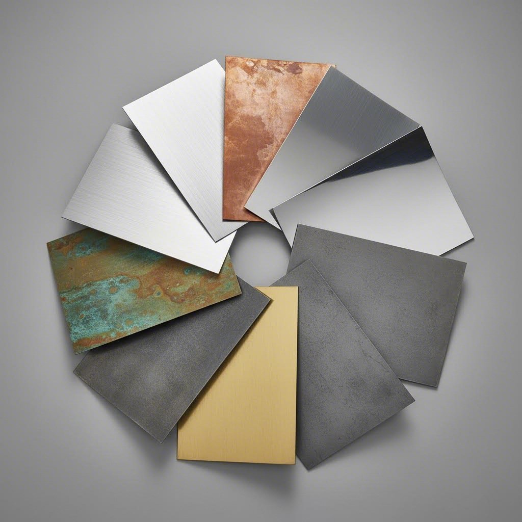
Jokainen metalli tuo omat ominaisuutensa mukanaan taiteprosessiin. Jotkut toimivat erinomaisesti paineen alaisina. Toiset puolestaan vastustavat halkeamisella, kimmoisella palautumisella tai kylmämuovautumisella, mikä edellyttää erityiskäsittelyä. Näiden käyttäytymisten ymmärtäminen ennen materiaalin valintaa säästää suurelta määrältä turhautumista myöhemmissä vaiheissa.
Tarkastellaan, miten yleiset metallit suoriutuvat taitekuormituksessa – ja mitä sinun tulee tietää älykkäiden valintojen tekemiseksi.
Alumiinin taiteominaisuudet ja huomioon otettavat seikat
Alumiinin keveys ja lujuus tekevät siitä suosituin valinta useilla toimialoilla. Mutta kun on kyse alumiinin taivuttamisesta, kaikki seokset eivät käyttäydy samalla tavalla. Alumiinilevyjen taivuttamisen ymmärtäminen alkaa sen tunnistamisesta, että seoksen koostumus ja karkaistuus vaikuttavat ratkaisevasti tuloksiin.
Seather Technologyn mukaan alumiinin pinta voi vahingoittua taivutuksen aikana, ja rakojen muodostuminen on mahdollista – erityisesti rautapitoisten komponenttien murtuessa. Leikkausvyöt voivat muodostua, mikä johtaa ennenaikaiseen rikkoutumiseen. Nämä ongelmat liittyvät suoraan alumiinin lujuuteen ja myötölujuuden nousuun.
Tässä mitä tekee alumiinilevyn taivuttamisesta haastavaa: eri seokset tarjoavat hyvin erilaisia muovattavuusominaisuuksia. Tarkastele näitä yleisiä vaihtoehtoja:
- 3003-alumiini: Helppoimmin taivutettava. Suuri venymä estää halkeamisen, joten se soveltuu erinomaisesti viemäreihin, kattoihin ja säiliöihin. Jos haluat sileitä taivutuksia vähimmällä vaivalla, 3003-tuote on oikea valinta.
- alumiini 5052: Tarjoaa erinomaisen taipuisuuden keskivahvalla tai korkeavahvalla lujuudella. Tätä seostetta käytetään usein meritekniikassa ja lääketeknisissä laitteissa, koska se muovautuu helposti ja siihen syntyy vähemmän halkeamia kuin kovemmissa vaihtoehdoissa.
- 6061 Alumiini: Vahva ja yleisesti käytetty rakenteisiin, mutta vaatii huolellista käsittelyä. Paksujen osien taipumissäteiden tulee olla suuremmat halkeamien ehkäisemiseksi. T6-muovattavuus on erityisen haastava; vältä teräviä kulmia ja harkitse lämpökäsittelyä muovattavuuden parantamiseksi.
Kun työskentelet taivutettavan alumiinilevyn kanssa, venymäprosentti on avainindikaattorisi. Suuren venymän seokset venyvät pidemmälle ennen rikkoutumista, mikä johtaa sulavampiin taivutuksiin ja vähemmän virheisiin. Tarkista aina materiaalitietolomake ennen suunnittelun lopullista vahvistamista.
0,125 tuuman paksulle 6061-T6:lle käytä sisäsädettä 1,5–3 kertaa materiaalin paksuus. Älä taivuta yli 86 astetta ilman pehmeäksi hehkuttamista.
Teräksen ja ruostumattoman teräksen taivutusvaatimukset
Taivutetut teräskomponentit muodostavat perustan lukemattomille sovelluksille – auton alustasta teollisuuslaitteiden kehysten rakenteisiin. Pehmeän teräksen suopea luonne tekee siitä vertailuperusteen muihin materiaaleihin nähden. Se hyväksyy tiukat taivutussäteet, sietää prosessimuutokset ja yleensä toimii ongelmitta.
Ruostumaton teräs kertoo eri tarinan. Vaikka sen korroosionkesto ja esteettinen ulkonäkö tekevät siitä välttämättömän arkkitehtuurissa, elintarviketeollisuudessa ja lääketekniikassa, se vaatii kunnioitusta muovausoperaatioissa.
Mukaan lukien SS Pro Fab , ruostumattoman teräksen taivutus palvelee keskeisessä asemassa useilla toimialoilla:
- Arkkitehtuuri ja rakentaminen: Kaarevat julkisivut, kaiteet, suojakaiteet, portaat ja kaidejärjestelmät
- Autoteollisuus ja liikenne: Pakoputket, alustakehykset, kiinnityslevyt, polttoainelinjat
- Lääketeollisuus ja farmasia: Kirurgiset instrumentit, implantit, tarkkuusputkimuodostelmat
- Ruokantuotanto: Kuljetinhihnastoja, kuljetusluiskeja, säiliöitä ja tuotantolaitteita
Haaste? Ruiske teräs kovettuu nopeasti taivutettaessa. Jokainen muovausoperaatio lisää pinnan kovuutta, mikä tekee seuraavista taivutuksista vaikeampia ja lisää halkeamisen riskiä. Tyypillisesti tarvitset suurempia taivutussäteitä kuin muiden terästen kanssa – usein vähintään 1×–2× materiaalin paksuus – ja monimutkaisissa monitaivutuksissa saattaa olla tarpeen välilämmitys.
Erikoismetallit ja niiden ainutlaatuiset haasteet
Alumiinin ja teräksen lisäksi useat erikoismetallit esittävät erityisiä taivutusominaisuuksia, joiden ymmärtäminen on arvokasta:
Kupari
Kupari kuuluu helpoimmalla taivutettavien levyjen joukkoon. Kuten Protolabs huomauttaa, kuparilla on korkea ductiliteetti – kyky venyä, taipua tai pitkittyä rikkoutumatta. Duktiilit metallit, kuten kupari, näyttävät tyypillisesti 20–60 % venymää ennen murtumista, kun taas hauraiden metallien alle 5 %. Tämä tekee kuparista erittäin suopean taivutusoperaatioissa, ja se hyväksyy säteet aina 0,5× materiaalin paksuuteen asti.
Messinki
Messinki yllättää monia insinöörejä sen muovattavuudella. Huolimatta sinkin sisällöstä, joka yleensä vähentää sitkeyttä, messinki taipuu odotettua helpommin. Suurimmassa osassa sovelluksia sopiva sisäsäde on vähintään 1× materiaalipaksuus. Materiaalin yhdistelmä korroosionkestävyydestä ja esteettisestä ulkomuodosta tekee siitä suositun valinnan dekoratiivisiin arkkitehtuurielementteihin.
Titanium
Titaani edustaa vastakkaista ääripäätä. Protolabsin sitkeysarvojen mukaan Ti-6Al-4V – yleisin titaaniseos – näyttää vain 10–14 %:n venymän verrattuna ruostumattoman teräksen 304:n 40–60 %:iin. Tämä rajoittunut sitkeys tarkoittaa, että titaania varten tarvitaan suurempia taivutussäteitä, hallittuja muovausnopeuksia ja usein korkeampia lämpötiloja onnistuneeseen taivutukseen.
Taivutettavuuteen vaikuttavat materiaaliominaisuudet
Neljä perusominaisuutta määrittää, miten jokin metalli reagoi taivutusvoimiin:
- Duktiilisyys: Mittaa, kuinka paljon materiaalia voidaan muovata ennen kuin se murtuu. Suurempi ductility tarkoittaa helpompaa taivutusta. Ajattele paperiliittimen taivuttamista verrattuna kuivan pastan murtumiseen – paperiliitin venyy ja vääntyy rikkoutumatta.
- Vetolujuus: Suurin vetojännitys, jonka materiaali kestää venytettäessä. Korkeampi vetolujuus vaatii yleensä suurempaa taivutusvoimaa ja saattaa rajoittaa saavutettavissa olevaa minimitaivutussädettä.
- Työkarkenemisalttius: Kuinka nopeasti materiaali karkenee muovauksen aikana. Voimakas työkarkeneminen (yleistä ruostumattomassa teräksessä ja joissain alumiiniseoksissa) rajoittaa muovattavuutta ja saattaa edellyttää välilämmitystä.
- Rakenteen rakeisuus: Suuntainen rakenne, joka muodostuu materiaalin valmistuksen aikana. Taivutus rakeisuuden kohtisuorassa suunnassa jakaa jännityksen tasaisemmin ja vähentää halkeamisen riskiä.
Materiaalin pehmeysluokan ratkaiseva merkitys
Pehmeysluokka kuvaa materiaalin kovuustilaa – ja sillä on suuri vaikutus taivutuksen onnistumiseen. Peuhkeammat luokat taipuvat helposti; kovemmat luokat vastustavat muodonmuutosta ja halkeavat helpommin.
Alumiinissa myötätysluokat kertovat tarkalleen, mitä voidaan odottaa:
- O-myötätys (hehkutettu): Peittein pehmein tila. Suurin muodonmuutoskyky helpoimpaan taivutukseen.
- H-myötätys (muovattu kovettunut): Eriasteisia kovuuksia. H14 tarjoaa kohtalaista kovuutta; H18 on täysin kova ja vaikea taivuttaa halkeamatta.
- T-myötätys (lämpökäsitelty): Liukoshehkutettu lujuuden saavuttamiseksi. T6 on erityisen haastava – harkitse hehkutusta ennen taivutusta, jos vaaditaan tiukkoja kaaria.
Sama periaate pätee kaikkiin materiaaleihin. Hehkutettu ruostumaton teräs taipuu helpommin kuin kylmämuovattu materiaali. Jousimyötätetty kupari saattaa haljeta siellä, missä pehmeästi hehkutettu kupari taipuu sujuvasti.
Oikean materiaali-myötätysyhdistelmän valinta luo perustan onnistuneelle taivutukselle. Mutta jopa optimaalisella materiaalivalinnalla virheitä voi esiintyä suunnitteluratkaisujen ja prosessiparametrien vuoksi. Rikkoontumisen, kimpoamisen ja pinnan vaurioiden syiden ymmärtäminen – sekä niiden estäminen – muodostuvat seuraavaksi keskeiseksi osaamisalueeksi.
Välttämällä yleisiä taivutusvirheitä
Olet valinnut täydellisen materiaalin. Taivutussäteen laskelmat näyttävät järkeviltä. Suunnitelma vaikuttaa virheetömältä näytöllä. Sitten taivutettu levy saapuu – ja jotain on vialla. Halkeamia ilmenee ulkopinnalla. Kääntöreunat kaartuvat siellä, missä niiden pitäisi olla suoria. Työkalumerkit pilaa tärkeitä pintoja.
Tuntuvatko tutuilta? Nämä viat eivät ole satunnaisia valmistusvirheitä. Ne ovat ennustettavissa olevia seurauksia suunnittelupäätöksistä, jotka tehtiin viikkoja tai kuukausia ennen tuotannon alkua. Hyvä uutinen? Ymmärtämällä kunkin vian syyn sinulla on mahdollisuus estää se.
Käydään läpi tarkkataivutuksessa yleisimmin esiintyviä ongelmia – ja varustaudutaan ratkaisuilla, jotka toimivat.
Halkeamien ehkäisy oikealla säteellä
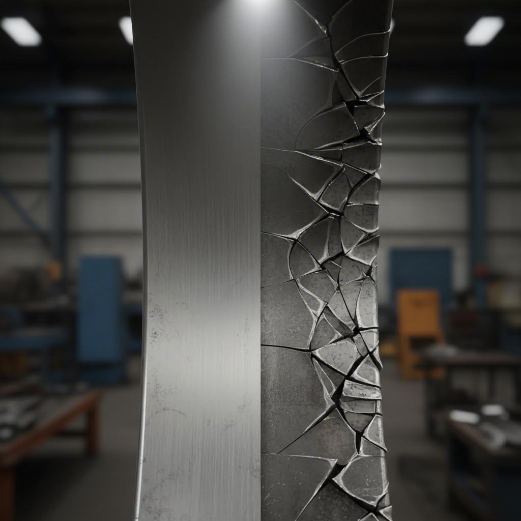
Halkeaminen edustaa katastrofaalinta taivutusvikausta. Kun materiaali murtuu, osa on hävikki. Ei mikään jälkikäsittely pelasta sitä. Silti halkeaminen on yhä yllättävän yleistä – pääasiassa sen takia, että suunnittelijat aliarvioivat materiaalin käyttäytymistä rasituksen alaisena.
Kun taivutat metallia, ulkopinta venyy, kun taas sisäpinta puristuu. Jos menee materiaalin venymisrajan yli, halkeamat etenevät veto puolelta. SendCutSendin mukaan riittämätön taivutuksen vapaus on ensisijainen syy – ilman asianmukaista jännitysten hallintaa korkeat jännityskeskittymät luovat heikkoja kohtia, jotka heikentävät rakenteellista kokonaisuutta.
Yleisiä syitä halkeamiseen ovat:
- Taivutussäde liian pieni materiaalin paksuuden ja muovattavuuden suhteen
- Taivutus vallin suuntaan nähden samansuuntainen eikä kohtisuora
- Puuttuva tai riittämätön taivutuksen vapaus risteävissä taivutusviivoissa
- Kovalentunut materiaali aiemmista muovausoperaatioista
- Korkeat lujuusluokat (kuten 6061-T6 alumiini) ilman pehmeäksihehkutusta
Toimivat ennaltaehkäisystrategiat:
- Määritä sisäinen taivutussäde vähintään 1× materiaalin paksuus – suurempi kovemmille materiaaleille
- Suuntaa taivutukset mahdollisuuksien mukaan kohtisuoraan valssausuuntaan nähden
- Lisää taivutuksen vapautusleikkaukset kulmiin, joissa taivutusviivat kohtaavat – pienet lovennot, jotka sallivat hallitun materiaalivirran
- Pyydä hehkutettua lujuutta monimutkaisille osille, jotka vaativat tarkkoja taivutuksia
- Konsultoi materiaalitietolehtiä vähimmäistaivutussäteen suositusten osalta, erityisesti sinun seoksesi ja paksuutesi mukaan
Taivutuksen vapautus mahdollistaa hallitun materiaalivirran, mikä vähentää repeämisen tai halkeamisen riskiä, erityisesti suuren rasituksen alueilla.
Jousieffektin hallinta suunnittelussasi
Kaikki materiaalit pyrkivät palautumaan alkuperäiseen litteään muotoonsa taivutuksen jälkeen. Tätä elastista palautumista – jota kutsutaan jousiefektiksi – ilmenee niin, että muodostamasi kulma ei ole sama kuin lopullinen kulma. Jos jousieffektiä ei oteta huomioon, 90 asteen taivutukset voivat rentoutua 92–94 asteeseen. Yhtäkkiä osat eivät sovi kokoonpanoihin, ja liitospinnat jäävät auki.
Mukaan lukien Dahlstrom Roll Form , jousieffekti tapahtuu, koska kun metallia taivutetaan, sisäinen alue puristuu, kun taas ulkoinen alue venyy. Puristavat voimat ovat heikompia kuin ulkopuolen vetovoimat, jolloin metallisi pyrkii palautumaan entiseen muotoonsa.
Mitä vaikuttaa kimpoamisen vakavuuteen:
- Materiaalin myötölujuus: Korkeampilujuusmateriaalit kimpoavat voimakkaammin
- Taivutussäde: Suuret säteet aiheuttavat suuremman kimpoamisen kuin tiukat taivutukset
- Materiaalin paksuus: Ohuemmat materiaalit näyttävät tyypillisesti enemmän elastista palautumista
- Taivutuskulma: Matalat kulmat kokevat suhteellisesti enemmän kimpoamista
Miten kompensoida tehokkaasti:
Tieto siitä, miten kimpoamista voidaan vastustaa, liittyy vähemmän estämiseen ja enemmän valmistautumiseen. Pääasiallinen menetelmä sisältää ylitauttaminen —taivuttamalla tiukempi kulma kuin vaaditaan, jotta materiaali rentoutuu haluttuun mittoihin. Jos tarvitset 90 astetta, saatat taivuttaa 88 astetta.
Metallin taivutuspalveluntarjoajanne käsittelee yleensä tämän kompensoinnin CNC-ohjauksellaan. Sinun tulisi kuitenkin:
- Ilmoittaa lopulliset kulmavaatimukset selvästi – älä ilmoita taivutuskulmia
- Määritä, mitkä pinnat ovat kriittisiä istuvuudelle ja toiminnalle
- Salli prototyyppien iteraatio tarkkojen kompensaatioarvojen määrittämiseksi
- Harkitse kovalta puristamista osille, joissa tarvitaan mahdollisimman vähän kimmoista palautumista – äärimmäinen paine vähentää joustavan palautumisen lähes täysin
Pintalaatua koskevat harkinnat ja työkalumerkit
Kaikki vauriot eivät vaaranna rakenteellista kokonaisuutta – mutta jotkut vauriot voivat kuitenkin estää projektin yhtä tehokkaasti. Työkalumerkit, naarmut ja pintadeformaatiot voivat tehdä osista hyväksymättömiä näkyvissä kohteissa tai tarkkuuskoottavissa kokoonpanoissa.
Taivutustoiminnassa työstötyökalu ja kuviokuori koskettavat suoraan materiaasi. Tämä kosketus jättää väistämättä jälkiä – kysymys kuuluukin, vaikuttavatko nämä jäljet sovellukseesi.
Yleisiä pintalaatuongelmia:
- Muottimerkit: V-kolun hartiat jättävät jälkiä taiteen alapuolelle
- Työkalumerkit: Yläkuoren aiheuttamat painumat materiaalin pinnalle
- Naarmut: Vetomerkkejä, jotka aiheutuvat materiaalin liukumisesta työkaluja vasten muovauksen aikana
- Appelsiinikuori-pinta: Karkea pinnan olemus, joka johtuu liiallisesta venymisestä
Riskejä lievittävät menetelmät:
- Määritä suojakalvo materiaaliin, joka pysyy paikoillaan taivutuksen aikana, kun pintalaadulla on ratkaiseva merkitys
- Pyydä uretaanista valssiosia, jotka pehmittävät kontaktia terästyökalun ja työkappaleen välillä
- Salli jälkitaivutuskäsittelytoimenpiteet, kuten hionta, kiillotus tai pinnoitus, piilottaaksesi pienet merkit
- Suunnittele osat piilotetuilla taivutussijoilla – sijoita taivutukset näkymättömille pinnoille, joissa työkalumerkit eivät ole merkityksellisiä
Räätälöityjen taivutettujen metalliosien kohdalla, jotka on tarkoitettu arkkitehtuurikäyttöön tai kuluttajien nähättäviksi, keskustele pintaehdoista valmistajan kanssa ennen tuotantoa. He voivat valita sopivat työkalut ja käsittelymenettelyt kriittisten pintojen suojaamiseksi.
Miksi taivutusjärjestyksellä on merkitystä monimutkaisille osille
Kuvittele laatikko, jossa on neljä reunusta. Kuulostaa yksinkertaiselta – kunnes huomaat, että neljännen reunuksen taivuttaminen vaatii tilaa, jonka kolmas reunus nyt estää. Tämä on esimerkki siitä tormays , ja se on yllättävän yleinen suunnitteluvirhe.
SendCutSendin valmistusasiantuntijoiden mukaan törmäykset tapahtuvat, kun osan geometria häiritsee taiteprosessia. On olemassa kaksi päätyyppiä:
- Konetörmäykset: Kun materiaali koskettaa taitekonetta (takalukitus, sivukehykset, työkalupitimet) muovauksen aikana
- Itsetörmäykset: Kun osan yksi osa häiritsee toista osaa myöhemmissä taiteissa
Taitejärjestyksen yleisperiaate:
Kuten mainittu HARSLEn taiteopas , kun taiteaan monimutkaisia osia useilla kulmilla, ensimmäisen ja toisen taiteen järjestyksellä on erittäin suuri merkitys. Yleissääntö: taite ulkoa sisään – muodosta ulommat kulmat ensin, sen jälkeen siirry sisempiin kulmiin. Jokaisen taiteen on otettava huomioon luotettava asettuminen seuraavia toimenpiteitä varten, eikä myöhäisemmät taiteet saa vaikuttaa aiemmin muodostettuihin muotoihin.
Suunnittelunäkökohdat törmäysten ehkäisemiseksi:
- Mallinna osa kolmiulotteisesti ja simuloi taivutusjärjestys ennen lopullisen suunnittelun valmistumista
- Varmista riittävän pitkä reuna, jotta työkalulla on kosketus koko muovauksen ajan
- Harkitse monimutkaisten osien jakamista useiksi yksinkertaisemmiksi komponenteiksi, jotka hitsataan tai liitetään yhteen
- Konsultoi valmistajaa suunnitteluvaiheessa – he voivat tunnistaa törmäysriskit ennen kuin työkalut valmistetaan
Geometrian vääristyminen taivutuksen läheisyydessä
Pyöreät reiät muuttuvat soikeiksi. Uurat venyvät. Leikatut alueet vääntyvät. Tämä geometrian vääristyminen tapahtuu, kun ominaisuudet sijaitsevat liian lähellä taivutusviivoja, ja materiaalin siirtyminen muovauksen aikana vetää tai työntää vierekkäisiä geometrioita sallituilta toleransseilta
SendCutSendin mukaan eri materiaalit reagoivat eri tavoin taivutukseen – pehmeämmät metallit venyvät helpommin, kun taas kovemmat metallit ovat alttiimpia halkeamiselle tai muille vääristymistyypeille. Etäisyys ominaisuuden ja taivutuksen välillä vaihtelee materiaalin ja paksuuden mukaan
Ennakoivien ohjeiden noudattaminen:
- Pidä reiät ja leikkaukset vähintään 2× materiaalin paksuuden verran taivutusviivojen ulkopuolella
- Tarkista materiaalikohtaisten väliarvojen vaatimukset valmistajan määrityksistä
- Suunnittelumääreet, joiden on pysyttävä pyöreinä tai tarkkoina tasomaisilla osioilla taivutuksen ulkopuolella
- Jos reiät on tehtävä lähelle taivutuksia, harkitse poraamista tai punchaamista muovauksen jälkeen eikä ennen sitä
Näiden vikojen ymmärtäminen muuttaa sinut suunnittelijasta, joka toivoo osien toimivan, insinööriksi, joka varmistaa niiden toimivuuden. Mutta viat eivät kuitenkaan esiinny eristyksissä – ne ilmenevät eri tavoin eri aloilla, joilla vaaditaan erilaisia toleransseja ja laatustandardeja. Tarkastellaan, miten metallin taivutus palvelee erityisiä sektoreita ja mitä kukin vaatii prosessilta.
Metallin taivutuksen käyttökohteet
Erilaiset teollisuudenalat eivät ainoastaan käytä metallin taivutusta – ne vaativat täysin erilaisia tuloksia samasta perusprosessista. Autokorirunkoon tarkoitettu kiinnike kohtaa rasitusehdot, sertifiointivaatimukset ja toleranssiodotukset, jotka eivät juurikaan muistuta arkkitehtonista fasadilevyä tai ilmailualan rakenteellista komponenttia.
Näiden toimialakohtaisten vaatimusten ymmärtäminen auttaa määrittelemään vaatimukset tarkasti, valitsemaan sopivat metallin taivutuspalvelut ja arvioimaan, voivatko mahdolliset toimittajat todella toimittaa sovelluksesi tarvitseman. Tarkastellaan, miten johtavat toimialat hyödyntävät tätä olennaista muovausprosessia.
Autoteollisuuden sovellukset ja IATF 16949 -vaatimukset
Autoteollisuus edustaa yhtä vaativimmista ympäristöistä metallin taivutuspalveluille. Alkaen alustakomponenteista ja suspensiorististä aina koriinsa ja rakenteellisiin vahvistuksiin asti, taivutettujen metalliosien on toimittava virheettömästi dynaamisen kuormituksen, ääriarvoisten lämpötilojen ja vuosikymmenten käyttöiän ajan.
Mukaan lukien teollisuuden valmistusasiantuntijat , autoteollisuuden levyvalmisteet muodostavat karkean, alustan osat, kiinnikkeet ja kantavat rakenteet, jotka määrittävät ajoneuvon kehikon, tukevat keskeisiä järjestelmiä ja varmistavat osien oikean asennon kokoonpanon aikana. Hyvin valmistetut metalliosat parantavat ajoneuvon lujuutta, törmäysturvallisuutta, ilmanvastusta ja ulkonäköä.
Tärkeitä seikkoja autoteollisuuden metallin taivutuksessa:
- IATF 16949 -sertifiointi: Tämä autoteollisuudelle spesifinen laadunhallintastandardi ylittää ISO 9001 -standardin ja edellyttää dokumentoituja prosessihallintamenetelmiä, vianehkäisymenetelmiä ja jatkuvan parantamisen protokollia. Toimittajat ilman tätä sertifikaattia eivät yleensä voi toimittaa OEM- tai Tier-1-asiakkaille.
- Tiukat tarkkuusvaatimukset: Autoteollisuuden komponenteissa vaaditaan korkea mitatarkkuus, jotta osat sopivat oikein suurissa tuotantomäärissä – osien on koottava oikein, olivatpa ne ensimmäisiä tai miljoonasarjan osia.
- Materiaalien jäljitettävyys: Jokainen levynpala on oltava jäljitettävissä alkuperäpaikkaansa asti, ja siihen liittyy sertifioitu tehtaan testausraportti, jossa on ilmoitettu kemiallinen koostumus ja mekaaniset ominaisuudet.
- Korkean lujuuden teräkset (AHSS): Modernit ajoneuvot käyttävät ylpeän näitä materiaaleja saavuttaakseen törmäysturvallisuustavoitteet samalla kun vähentävät painoa. AHSS:n taivutus aiheuttaa ainutlaatuisia haasteita, kuten voimakasta kimmoista ja tiukempia vähimmästaivutussäteen vaatimuksia.
Kuljetusalan asiakkaille tarjottavien kulmataivutuspalvelujen on osoitettava paitsi tekninen osaaminen, myös järjestelmällinen laadunhallinta, joka takaa johdonmukaiset tulokset tuotantosarjoissa, joissa valmistetaan tuhansia tai miljoonia osia.
Arkkitehtoninen metallin taivutus esteettistä tarkkuutta varten
Kun metalli muodostuu rakennuksen visuaaliseksi identiteetiksi, säännöt muuttuvat dramaattisesti. Arkkitehtoniset sovellukset asettavat etusijalle pinnan laadun, visuaalisen johdonmukaisuuden ja tarkan geometrisen tarkkuuden, jotka luovat saumattoman suunnittelujatkuvuuden suurissa asennuksissa.
Ruostumattoman teräksen taivutus täyttää tärkeitä arkkitehtonisia tehtäviä, kuten kaarevat julkisivut, kaiteet, suojakaiteet, portaat ja kaiteet valmistajien mukaan. Nämä sovellukset edellyttävät virheettömiä pinnanloppukäsittelyjä, jotka säilyvät näkyvillä rakenteen koko käyttöiän ajan.
Arkkitehtonisen metallin taivutuksen prioriteetit:
- Pinnanlopuksiapilan säilyttäminen: Työkalumerkit, naarmut tai käsittelyvauriot, jotka saattavat olla hyväksyttäviä piilotetuille teollisuuskomponenteille, eivät ole hyväksyttäviä näkyville pinnoille. Suojakalvot, erikoistyökalut ja varovainen käsittelymenettelyt ovat välttämättömiä.
- Kaarevuuden yhdenmukaisuus: Useita paneeleja ulottuvien kaarevien elementtien on täsmättävä tarkasti toisiinsa. Jopa pienet poikkeamat taivutussäteessä aiheuttavat näkyviä epäjatkuvuuksia, kun paneelit asennetaan vierekkäin.
- Sääkestävät materiaalit: Ruostumaton teräs, alumiini ja pinnoitettu hiiliteräs on kestettävä vuosien mittaiset ympäristövaikutukset ilman korroosiota tai pinnan heikkenemistä.
- Laajan muodon ominaisuudet: Arkkitehtuuripaneelit ylittävät usein standardilevyjen koot, mikä edellyttää rullataivutusta tai puristussorvia, jotka kestävät taipumatta pitkiä mittapituuksia.
Korkeat esteet estetiikassa tarkoittavat, että arkkitehtuuriprojektit vaativat usein näyten hyväksynnän, mallipaneelien valmistuksen ja yksityiskohtaiset pintakuvakkeet, joita teollisuussovellukset saattavat jättää kokonaan huomiotta.
Teollisuuslaitteet ja suurta vahvuutta vaativat taivutukset
Teollisuussovellukset testaavat metallin taivutuskyvyn ylärajoja. Laitteiden rungot, koneensuojat, kuljettimen osat ja rakenteelliset tuet sisältävät usein materiaalipaksuuksia, jotka mitataan tuumien murto-osina eikä kalvoilla – mikä edellyttää erikoislaitteita ja asiantuntemusta.
Raskaiden valmistajien mukaan suurten metallilevyjen taivutus raskaiden projektien tarpeisiin palvelee alueita, jotka vaihtelevat rakennus- ja energiasektorilta aina valmistuslaitteisiin asti. Suurten metallilevyjen taivuttaminen tarkasti ja tehokkaasti on olennaista, jotta voidaan täyttää projektikohtaiset vaatimukset ja määräajat.
Teolliset ja suurten paksuusten huomioonotot:
- Suuritehoiset laitteet: Paksut levyt vaativat merkittävästi enemmän taivutusvoimaa. Puolen tuuman teräslevy saattaa vaatia jopa 10-kertaisen voiman tavalliseen levymetalliin verrattuna, mikä rajoittaa sitä, mitkä metallin CNC-taivutuskoneet pystyvät käsittelemään työtä.
- Materiaalin eheys rasituksen alaisena: Raskaiden komponenttien on usein kannettava suuria kuormia. Taivutuslaatu vaikuttaa suoraan rakenteelliseen suorituskykyyn ja turvallisuustekijöihin.
- Hitsausvalmistelu: Monet teolliset kokoonpanot vaativat hitsattuja liitoksia. Taivutustarkkuus varmistaa oikean asennuksen ja vähentää vääristymistä hitsauksen aikana.
- Mittatoleranssit: Vaikka teolliset toleranssit saattavat olla vähemmän tiukkoja kuin lentokonetarpeet, ne ovat silti tärkeitä kokoonpanossa ja toiminnassa. Tyypilliset toleranssit vaihtelevat ±0,030" ja ±0,060" välillä osan koosta ja sovelluksesta riippuen.
Ilmailusovellukset ja tarkkuusvaatimukset
Ilmailuteollisuus edustaa metallin taivutuksen tarkkuuden huippua. Lentokoneiden rakenteisiin, moottorikoteloihin tai avaruusalusten kokoonpanoihin tarkoitetut komponentit täytyy valmistaa äärimmäisen tiukkojen standardien mukaisesti, joissa virhemarginaali on täysin nolla.
Pyörätys soveltuu ilmailualan sovelluksiin, kuten siipirakenteisiin, rungon osiin ja rakennekomponentteihin, joissa tarvitaan kaarevia profiileja seuraavien mukaan valmistusteknologian lähteet nämä osat vaativat toleransseja, jotka mitataan tuhannesosina tuumasta.
Ilmailuteollisuuden metallin taivutusvaatimukset:
- AS9100-sertifiointi: Ilmailulle tarkoitettu vastine IATF 16949 -laatustandardille, joka sisältää lisävaatimuksia konfiguraationhallintaan, riskien arviointiin ja toimittajavaatimuksien etenemiseen, jotka ohjaavat osien valmistusta ja dokumentointia.
- Erikoismateriaalit: Titaani, Inconel ja ilmailuluokan alumiiniseokset aiheuttavat ainutlaatuisia taivutushaasteita, kuten rajallinen ductility, suuri kimmoisa palautuminen (springback) ja kapeat muovausikkunat.
- Ensimmäisen artiklan tarkastus (FAI): Tuotantosarjojen ennen ilmailukomponenttien mitat tarkistetaan perusteellisesti vastaamaan teknisiä vaatimuksia – jokainen määritelty mitta mitataan ja dokumentoidaan.
- Materiaalitodistukset: Raaka-aineiden on täytettävä ilmailualan eritelmät täydellä jäljitettävyydellä. Virheellisiä materiaaleja ei voida käyttää riippumatta fyysisestä ulkonäöstä.
Materiaalien haasteiden, dokumentointivaatimusten ja tarkkuusvaatimusten yhdistelmä tarkoittaa, että ilmailuun soveltuvat levyjen taivutuspalvelut edustavat teollisuuden erikoistunutta tasoa – ja hinnoittelu heijastaa tätä.
Palvelukykyjen yhdistäminen toimialan tarpeisiin
Oikean metallin taivutuspalvelujen kumppanin valitseminen tarkoittaa, että katsoo perusvarusteluetteloiden yli. Valmistajan kanssa tuodut sertifikaatit, laatuohjelmat ja toimialakokemus määrittävät, kykeneekö se todella palvelemaan alasi toimialan vaatimuksia.
Kun arvioit mahdollisia toimittajia, harkitse, mitkä alan kohtaiset kyvykkyydet ovat tärkeimpiä sovelluksellesi. Kauppa, joka sopii erinomaisesti arkkitehtuurisovelluksiin, saattaa puuttua dokumentaatiojärjestelmiltä, joita autoala vaatii. Lentokonetodistetulla tilalla saattaa olla liikaa — ja se on ylihinnoiteltu — yleisiin teollisuuskomponentteihin.
Seuraavassa osiossa tutkimme, kuinka taivutusmenetelmiä voidaan systemaattisesti yhdistää tiettyyn osan geometriaan, määrävaatimuksiin ja sovellustarpeisiin — antaen sinulle pohjan päätösten tekemiseen sekä prosessin valinnassa että toimittajan arvioinnissa.
Oikean taivutusmenetelmän valitseminen
Sinulla on osasuunnitelma valmis. Nyt nousee keskeinen kysymys: mikä taivutusmenetelmä todella sopii projektiisi? Vastaus ei aina ole ilmeinen — ja väärä valinta tarkoittaa tuottomattoja työkalukustannuksia, pidennettyjä toimitusaikoja tai osia, jotka eivät yksinkertaisesti täytä teknisiä vaatimuksia.
Tässä on todellisuus: jokainen taivutustekniikka loistaa tietyissä tilanteissa ja kamppailee toisissa. Metallilevyjen taivutuskone, joka tuottaa virheettömiä kulmatukia, saattaa olla täysin väärä kaarevien arkkitehtuuripaneeleiden kanssa. Suurten sarjojen valmistukseen optimoidut levyjen taivutuskoneet saattavat osoittautua tehottomiksi prototyyppimääriin.
Katsotaanpa tarkasti, kuinka menetelmä kohdistetaan projektiin – olitpa sitten pienyritys tai hankintapalvelun käyttäjä ammattilaisten CNC-taivutuspalveluista.
Taivutusmenetelmän yhdistäminen osan geometriaan
Osin muoto määrittää, mitkä tekniikat edes kelpaavat vaihtoehdoiksi. Ennen kuin harkitset määrää tai kustannuksia, geometria eliminoi tietyt menetelmät täysin.
Kulmikkaita taivutuksia tasolevyssä tai levyssä
Puristusjarrutus hallitsee tätä alaa. Tarvitsetpa yksinkertaisia L-kiinnikkeitä, monimutkaisia kotelointeja useilla taivutuksilla tai tarkkuuskehiksiin osia, puristusjarrut tuottavat kulmatasoisia muotoja levyistä tehokkaasti. Menetelmä soveltuu kaikille paksuudelle, ohuista levyistä raskaisiin plaatteihin – edellyttäen että toimittajalla on riittävä painovoimakapasiteetti.
Kaarevat profiilit ja sylinterimäiset muodot
Kun suunnittelussa tarvitaan kaaria, sylintereitä tai kartiomaisia muotoja, rullataivutus on selvä valinta. Mukaan lukien RF Corporationin valmistusanalyysi , rullamuovaus tarjoaa joustavamman ratkaisun leikkauspituuteen ja osien suunnitteluun, mikä helpottaa mukautettujen vaatimusten täyttämistä tehokkuuden vaarantumatta. Toisin kuin puristusjarrutus, joka on rajoitettu työkalujen leveyteen, rullamuovauksessa osien pituus voi olla käytännössä rajoittamaton.
Putket ja putket, jotka vaativat tiukkaradiusia taivutuksia
Pyöreä vetotaivutus käsittelee putkimaista geometriaa, jota ei painetaivuttimella eikä rullataivuttimella voida käsitellä. Pakoputket, hydraulijohdot, huonekalurungot ja käsikaiteet vaativat yleensä tämän menetelmän sisäsylinterin tuen poikkileikkauksen vääristymisen estämiseksi.
Kysy itseltäsi ensin nämä geometriakysymykset:
- Vaadiiko osani kulmia tai kaaria?
- Työskentelevätkö levy-/levyvarastojen vai putkimateriaalien parissa?
- Mikä on suurin taivutussäde, jonka suunnittelu määrittää?
- Tarvitsenko useita peräkkäisiä taivutuksia, ja voivatko ne häiritä toisiaan?
Määränsidonnaiset harkinnat prototyypistä tuotantoon
Geometria kaventaa vaihtoehtojasi. Määrä määrittää, mitkä jäljelle jäävät ovat taloudellisesti järkeviä.
Prototyyppi ja pienet erät (1–50 osaa)
CNC-levymetallin taivutus puristimilla on yleensä edullisinta pienillä eräkokoilla. Asennusaikojen on vähäiset verrattuna erikoistyökaluihin liittyviin kustannuksiin. Säädettävät parametrit tarkoittavat, että sama laitteisto soveltuu erilaisten suunnitelmien valmistukseen ilman uudelleenkalustamista. Useimmat metallin taivutusliikkeet voivat käsitellä nopeasti toteutettavat prototyyppitilaukset olemassa olevilla vaaja- ja noutatyökalusarjoilla.
Keskipitkät tuotantosarjat (50–5 000 osaa)
Tämä välimatka edellyttää huolellista analyysiä. Puristimet säilyvät kilpailukykyisinä, mutta asennusaika jakautuu suuremmalle määrälle osia. CNC-metallin taivutuskoneet, joissa on automaattiset työkalunvaihtimet ja offline-ohjelmointi, voivat merkittävästi vähentää kappalekohtaisia kustannuksia näillä sarjakooilla.
Suuret tuotantosarjat (5 000+ osaa)
Tässä vaiheessa rullamuotoilu voi mahdollisesti muuttaa tuotantotaloutta. Mukaan valmistusprosessien vertailuihin , rullamuotoilu on huomattavasti nopeampaa kuin puristustaivutus, ja sen tuotantonopeus ylittää 100 jalkaa minuutissa – nopeutta, johon puristimet eivät yksinkertaisesti pysty.
Mikä on kompromissi? Rullamuovauksessa tarvitaan omistautuneita työkalusarjoja, jotka edustavat merkittävää alkupanostusta. Tämä panostus on järkevä vain, jos tuotantotilavuus sitä oikeuttaa. Oikeille projekteille rullamuovaus tarjoaa:
- Erinomaisen nopeuden ja läpimennyyskyvyn jatkuvissa profiileissa
- Tarkemmat toleranssit sekä pituudessa että reikien sijoituksessa
- Puhtaat ulkonäköominaisuudet, vähemmän näkyviä työkalujälkiä
- Suora syöttö teräskeloista – ei tarvetta esileikattuina levyinä, mikä vähentää materiaalin käsittelykustannuksia
Kustannustekijät eri taivutusmenetelmissä
Tilavuus kertoo osan kustannustarinasta. Useat muut tekijät vaikuttavat kuitenkin projektin kokonaiskustannuksiin – joskus jopa dramaattisesti.
Työkaluinvestointi
Puristintaivutuksessa käytetään vaihdettavia vasara- ja kuulityökalusarjoja. Standardityökalut riittävät useimpiin yleisiin sovelluksiin, mikä pitää alkuinvestoinnit matalina. Mukautetut työkalut lisäävät kustannuksia, mutta ne jaetaan tuotantotilavuuden kesken.
Rullamuovaus vaatii omat rullajoukot, jotka on suunniteltu tietyn profiilin mukaan. Nämä räätälöidyt työkalut maksavat huomattavasti enemmän alussa, mutta ne tuottavat alhaisemmat kappalekohtaiset kustannukset suurilla volyymeillä. Pyörivä taivutus vaatii samankaltaisesti sovelluskohtaisia työkaluja – taivutusmuotteja, mandrelleja, pyyhkäisymuotteja – jotka vastaavat putken halkaisijaa ja taivutussädettä.
Materiaalin käyttö
Rullamuovaukseen syötetään suoraan kelasta, mikä yleensä maksaa vähemmän painoyksikköä kohti kuin esileikattu levy, ja josta syntyy vähemmän hukkapaloja. Puristinputsausta varten tarvitaan leikatut työkappaleet ennen muovaukset – mikä lisää käsittelyvaiheita ja mahdollista hävikkiä.
Toissijaiset toiminnot
Mieti, mitä tapahtuu taivutuksen jälkeen. Osille saattaa olla tarvetta:
- Reikien punchaamiseen tai poraukseen
- Välilevyn asennus
- Hitsaamiseen tai kokoonpanoon
- Pintakäsittely
Jotkin taivutuspalvelut integroivat nämä toiminnot samalle linjalle; toiset edellyttävät erillistä käsittelyä. Yhdistetyt toiminnot pienentävät usein kokonaiskustannuksia ja lyhentävät toimitusaikoja verrattuna monen toimittajan toimitusketjuihin.
Taivutusmenetelmien vertailu: Päätöksenteon viitekehys
Käytä tätä vertailutaulukkoa arvioidaksesi nopeasti, mikä taivutustapa sopii projektisi parametreihin:
| Kriteerit | Kaaren kaaruminen | Rullataivutus/muovaus | Pyörivä vetoskaarrelaite |
|---|---|---|---|
| Osan geometria | Lehtimateriaalin kulmakaarat | Kaarevat profiilit, sylinterit, kaaret | Putket ja putkistot tiukoilla säteillä |
| Tuotannon tehokkuutta | Paras pienille–keskisille volyymeille; vaatii paljon asetuksia suurissa volyymeissa | Suurvolyyminen tuotanto; nopeudet jopa 100+ ft/min | Prototyyppivaiheesta keskisuuriin määriin |
| Toleranssikyky | tyypilliset toleranssit ±0,010" – ±0,030" CNC-laitteistoille | Tarkemmat toleranssit pituudelle ja reikien sijoittelulle verrattuna puristinsorvia | Erinomainen toistettavuus putkigeometriassa |
| Työkaluinvestointi | Pienet–kohtaiset; standardityökalut laajasti saatavilla | Korkea alkuinvestointi; erityiset rullajoukot vaaditaan | Kohtalainen tai korkea; sovelluskohtaiset muottisylinterit ja muottilevyt |
| Materiaalikäsittely | Edellyttää esileikattuja tyhjiä levyjä | Syötetään kelasta; vähentää käsittelyä ja jätettä | Leikattuja putkia tai jatkuvaa syöttöä |
| Pinta-laatu | Saattaa näyttää muottimerkkejä; lievitys mahdollista | Vähemmän näkyviä työkalumerkkejä; siistimpi ulkonäkö | Erinomainen, kun oikein varusteltu; muottisylinteri estää rypleitä |
| Tyypilliset sovellukset | Kiinnikkeet, kotelot, alustat, paneelit | Arkkitehtonisia kaaria, säiliöitä, rakenteellisia profiileja, kehyksiä | Pakoputkistot, hydraulijohdot, käsikaiteet, kalusteet |
Valintasi tekeminen: Käytännönläheinen lähestymistapa
Epävarma vielä, mikä menetelmä sopii projektiisi? Työstä läpi tämä päätösjärjestys:
- Määritä geometriavaatimukset – Kulmat vai kaaret? Levy vai putki? Tämä poissulkee välittömästi yhteensopimattomat menetelmät.
- Aseta määräodotukset – Prototyyppimäärät suosivat joustavuutta; tuotantomäärät palkitsevat erikoistunutta varustusta.
- Laske kokonaiskustannus – Sisällytä työkalutuksen poistot, materiaalikustannukset, jälkikäsittelytoiminnot ja logistiikka. Halvin kappalehinta ei aina tarkoita alinta kokonaiskustannusta.
- Varmista toleranssivaatimukset – Joidenkin menetelmien tarkkuus on parempaa kuin toisten. Varmista, että valitsemasi menetelmä pystyy todella täyttämään vaaditut spesifikaatiot.
- Arvioi toimittajien kykyjä – Kaikki metallin taivutusliikkeet eivät tarjoa kaikkia menetelmiä. CNC-taivutuspalvelut, joilla on useita prosessivaihtoehtoja, voivat suositella parhaiten sopivan vaihtoehdon tietyille parametreillesi.
Olitpa sitten harrastetaivuttaja, joka arvioi omaa laitteistoaan, tai insinööri, joka hankkii palveluja taivutuspalveluntuottajilta, tämä viitekehys ohjaa sinut kohti menetelmiä, jotka vastaavat todellisia projektitarpeitasi – ei pelkästään sitä, mikä on saatavilla tai tuttua.
Kun olet valinnut taivutusmenetelmäsi, seuraava haaste nousee: suunnitelmien valmistelu tuotantoon onnistuneesti. Oikea tiedostojen valmistelu, toleranssien määrittely ja valmistettavuuden huomioon ottaminen voivat merkitä eroa saumattoman valmistuksen ja kustannustehokkaiden uudelleen käsittelyjen välillä.
Valmista suunnitelmasi tuotantoon
Olet valinnut oikean taivutusmenetelmän ja määritellyt sopivat materiaalit. Mutta tässä vaiheessa monet hankkeet jäävät kuitenkin kesken: suunnittelun ja valmistuksen välisessä siirtymisessä. Puutteelliset piirustukset, epäselvät toleranssit ja puuttuvat tekniset tiedot pakottavat metallin taivutuspalveluntarjoajasi arvaamaan – ja arvaaminen johtaa viivästyksiin, uusiin tarjouspyyntöihin ja osiin, jotka eivät vastaa alkuperäistä tarkoitustasi.
Sileän tuotantoprosessin ja viikkojen kestävän sähköpostikeskustelun ero usein riippuu siitä, kuinka hyvin olet valmistanut suunnitelmapakettisi. Käytät sitten verkkopohjaisia levyjen taivutusalustoja tai teet yhteistyötä paikallisen valmistajan kanssa, nämä valmisteluperiaatteet pätevät yleisesti.
Valmistettavuuden huomioon ottaminen taivutustoimissa
Valmistettavuuden suunnittelu (DFM) ei ole vain muodikas ilmaisu – se on menetelmä, joka estää kalliit yllätykset valmistuksen aikana. Kun sovellat taustutusoperaatioihin tarkoitettuja DFM-periaatteita, olet käytännössä ratkaisemassa ongelmia etukäteen ennen kuin ne ilmenevät tuotantolaitoksella.
Mukaan lukien levymetallisuunnittelun asiantuntijat , ja DFM:n huomioiminen teknisissä piirustuksissa auttaa optimoimaan levymetallisuosituksia valmistajille. Seuraavat periaatteet ansaitsevat huomiosi:
Pitäkää taivutussäde yhtenäinen koko osassa
Saman säteen käyttäminen kaikissa taivutuksissa vähentää työkaluvaihtojen määrää ja parantaa tehokkuutta. Aina kun valmistaja vaihtaa työkaluja, se lisää aikaa ja saattaa aiheuttaa vaihtelua. Kuten Protolabsin suunnitteluohjeissa mainitaan, vakiosäteet kuten .030", .060", .090" ja .120" ovat saatavilla 3 päivän toimitusajalla – ei-vakioidut säteet voivat pidentää toimitusaikaasi.
Noudattakaa minimilistan pituusvaatimuksia
Liian lyhyitä reunoja ei voida kiinnittää asianmukaisesti taivutuskoneen työkaluihin. Yleissääntö: vähimmäisreunapituuden tulee olla vähintään 4 kertaa materiaalin paksuus. Tätä lyhempi reunapituus aiheuttaa epäjohdonmukaisia taivutuksia tai osia, joita ei yksinkertaisesti voida muodostaa.
Sijoita reiät ja muut ominaisuudet pois taivutusviivoilta
Taivutuksen lähellä olevat ominaisuudet vääristyvät muovauksen aikana. Protolabs määrittelee, että ohuissa materiaaleissa (0,036" tai ohuempia) reikien tulee olla vähintään 0,062" etäisyydellä materiaalin reunoista ja paksuissa materiaaleissa vähintään 0,125" reunoista. Rei'ille, jotka sijaitsevat lähellä taivutuksia, tämä etäisyys tulisi kasvattaa estääkseen soikeaa vääristymistä.
Ota jousieffekti huomioon toleranssimäärittelyissä
Valmistaja kompensoi jousieffektin muovauksen aikana, mutta sinun on määriteltävä vaadittu lopullinen kulma – ei muodostettu kulma. Alalla yleisten standardien mukaan kaikkien taivutuskulmien toleranssina tulee odottaa ±1 astetta. Jos tiukemmat toleranssit ovat kriittisiä, keskustele niistä etukäteen.
Valmistajat, joilla on kattava DFM-tuki, kuten Shaoyi , voi tarkistaa suunnittelusi ennen tuotannon aloittamista – tunnistaa mahdolliset ongelmat ja ehdottaa optimointeja, jotka vähentävät iteraatioita ja nopeuttavat aikatauluja.
Teknisten piirrustusten ja tiedostojen valmistelu
Tekniset piirrustuksesi toimivat ensisijaisena viestintävälineenä suunnittelutavoitteesi ja valmistajan toteutuksen välillä. Epätäydelliset tai epäselvät piirrustukset pakottavat palveluntuottajat tekemään oletuksia – ja nämä oletukset eivät välttämättä vastaa vaatimuksiasi.
Valmistusasiakirjojen asiantuntijoiden mukaan tekniset piirrustukset ovat olennaisia tarkkoihin levyvalmisteisiin. Keskeisiä elementtejä ovat selkeät määritelmät mitoille, toleransseille, materiaaleille, pinnoitteille sekä prosesseille kuten taivutukselle ja hitsaukselle.
Kaikkien piirrustusten on sisällettävä seuraavat keskeiset elementit:
- Otsikkotaulu: Piirustusnumero, osakuvailu, yritystiedot, mittakaava ja versiotaso
- Materiaalimäärittely: Määritä tyyppi, luokka, paksuus ja lujuus (esim. "5052-H32 alumiini, 0.090" paksu")
- Taivutusmääritykset: Taivutuksen sisäsäde jokaiselle taivutukselle, taivutuskulmat ja taivutusjärjestys, jos se on kriittistä
- Mittatoleranssit: Yleistoleranssit sekä erityisvaatimukset kriittisille ominaisuuksille
- Pintalaadun vaatimukset: Määritä mahdolliset pintakäsittelyvaatimukset, suojakalvojen tarve tai alueet, joissa työkalumerkit eivät ole sallittuja
- Rakosuunta: Ilmoita rullaussuunnan vaatimukset, jos taivutuksen suunta suhteessa rakoon on tärkeä
Laskentaprosessia helpottavat tiedostomuodot:
Useimmat CNC-levytaivutuskoneiden toiminnot perustuvat 3D-CAD-malleihin, joita täydentäävät 2D-piirrustukset. Toimita:
- STEP- tai IGES-tiedostot: Yleismaailmalliset 3D-muodot, jotka useimmat CAM-ohjelmistot voivat tuoda
- Natiivit CAD-tiedostot: SolidWorks-, Inventor- tai AutoCAD-tiedostot, jos valmistajasi käyttää yhteensopivaa ohjelmistoa
- PDF-piirustukset: Mitat, toleranssit ja huomautukset, joita 3D-mallit eivät välitä
- Litteet kuviotiedostot: Jos olet laskenut taivutussallitukset, litteän tyhjämittapiirustuksen antaminen säästää valmistajan uudelleenlaskennalta – vaikka he tarkistavatkin laskelmasi
Epätäydellinen dokumentaatio on yksi pääasiallisista projektien viivästyksien syistä. Valmistajat, joilla ei ole riittävästi tietoa, joutuvat joko pyytämään selvennystä (mikä lisää aikaa aikatauluusi) tai tekemään oletuksia (jolloin osat saattavat jäädä rikkomatta vaatimuksia)
Toleranssivaatimusten tehokas viestintä
Toleranssien määrittäminen erottaa harrastelijan suunnittelupalvelut ammattilaisten paketeista. Epämääräiset vaatimukset kuten "tiukka" tai "lähellä" eivät tarkoita mitään työpajassa. Selkeät, mitattavat toleranssit antavat valmistajalle selkeät tavoitteet – ja selkeät hyväksymiskriteerit.
Mukaan lukien ostospecialistit , toleranssien täytyy olla kirjallisessa muodossa. Ilman tarkkoja toleranssiarvoja asiakirjoissasi toimittajat voivat käyttää omaa harkintaansa – eikä se välttämättä vastaa tarpeitasi.
Toleranssit, jotka on määriteltävä nimenomaisesti:
| Mitatyyppi | Tyypillinen standarditoleranssi | Mitä täsmentää |
|---|---|---|
| Kaareutumiskulma | ±1 astetta | Vaadittu lopullinen kulma (ei muodostettu kulma) |
| Kaari säde | ±0,010" - ±0,015" | Sisäsäde; huomaa, jos mitattu keskiviivalta |
| Lineaariset mitat | ±0,010" - ±0,030" | Kokonaispituus, laippojen korkeudet, ominaisuuksien sijainnit |
| Reiän ja taiteen välinen etäisyys | ±0,015" – ±0,030" | Tärkeää kokoonpanon kohdistamiselle |
| Siirtymäkorkeus | ±0.012" | Z-muotoisille profiileille ja joggle-ominaisuuksille |
Tärkeät viestintäkäytännöt:
- Tunnista kriittiset mitat: Kaikki mitat eivät ole yhtä tärkeitä. Merkitse tiukemmat toleranssit niille ominaisuuksille, jotka ovat ratkaisevia istuvuudelle, toiminnalle tai kokoonpanolle – anna ei-kriittisten mittojen käyttää standarditoleransseja.
- Määritä mittausviitepisteet: Onko taivutussäde mitattu sisäpuolelta, ulkopuolelta vai keskiviivalta? Mistä kohtaa tämä mitta alkaa ja päättyy?
- Pyydä laatudokumentaatiota: Kriittisiin sovelluksiin pyydä tarkastuskertomuksia, jotka näyttävät mitatut arvot keskeisille mitoille. Tämä varmistaa, että osat täyttävät vaatimukset.
- Keskustele toleranssien saavutettavuudesta: Joidenkin toleranssien saavuttaminen maksaa enemmän. Jos määrität ±0,005" jokaiselle mitalle, odota korkeampia hintoja ja pidempiä toimitusaikoja. Säilytä tiukat toleranssit vain niille mitoille, jotka todella niitä vaativat.
Tiukemmat toleranssit voivat maksaa enemmän – mutta ne usein estävät suurempia ongelmia, kuten hylättyjä profiileja, asennusviiveitä ja hätätilauksia.
Tarjousprosessin tehostaminen
Siihen, kuinka nopeasti saat tarkat tarjoukset, vaikuttaa suuresti se, kuinka täydellistä tietoa annat. Puuttuvat tiedot aiheuttavat selvennyspyyntöjä, jotka venyttävät aikataulua päivillä. Täydelliset tiedot paketoidaan nopeammin – ja tarkemmin.
Tiedot, joita metallintaittopalveluntarjoajasi tarvitsee:
- Täydelliset CAD-tiedostot ja piirustukset kaikkien yllä mainittujen määriteltyjen tietojen kanssa
- Määränvaatimukset: Prototyyppimäärä, alustava tuotantoerä ja arvioitu vuosittainen määrä
- Materiaalipreferenssit: Tai joustavuus ehdottaa vaihtoehtoja, jotka saattavat vähentää kustannuksia
- Aikatauluvaatimukset: Milloin tarvitset osia ja onko nopeutettu tuotanto hyväksyttävissä korkeammalla hinnalla
- Laadutodistukset: Vaativatko sovelluksesi IATF 16949-, AS9100- tai muita sertifioituja laadunhallintajärjestelmiä?
- Toissijaiset toiminnot: Vaatimukset kiinnikkeiden asentamiseen, hitsaukseen, viimeistelyyn tai kokoonpanoon
- Pakkaus ja kuljetus: Erityiskaiveltavuusvaatimukset pinnansuojaukselle tai logistiikalle
Kun etsit räätälöityjä levyjen taivutuspalveluja – olipa kyseessä hakusanana "sheet metal bending near me" tai palveluiden arviointi hakusanalla "metal bending services near me" – ne toimittajat, jotka vastaavat nopeimmin tarkoilla tarjouksilla, ovat yleensä sellaisia, joiden tarjousprosessi sopii täydellisesti valmisteltuihin suunnitteluaineistoihin. Valmistajat, jotka tarjoavat nopean tarjoustyön kääntymisajan, kuten Shaoyin 12 tunnin vastausvelvoite, voivat merkittävästi lyhentää hankintaprosessiasi, kun tarjoat kaikki tiedot etukäteen.
Asioiden kunnollinen valmistelu muuttaa suunnittelusta tuotantoon siirtymisen turhauttavasta vaiheesta sujuvaksi työnkulkuksi. Kun dokumentaationne on valmis ja toleranssit on selkeästi määritelty, olette hyvällä mallilla arvioimaan toimittajia tehokkaasti sekä skaalaamaan prototyypistä tuotantoon luottavaisin mielin.
Siirtyminen eteenpäin taiteprojektissanne
Olette omaksunut perusteet, tutustunut taitekäytäntöihin ja oppinut estämään ne virheet, jotka tuhoavat projektit. Nyt on aika toimia – muuttaa tieto tuloksiksi. Olettepa sitten hankkimassa ensimmäistä prototyyppiänne tai skaalaamassa tuotantomääriin, teidän seuraavat päätökset määrittävät sen, onnistuuko projektinne vai epäonnistuuko se.
Etenevä polku vaihtelee sen mukaan, missä kohtaa projektisykliänne olette. Suunnittelijalle, joka viimeistelee teknisiä tietoja, tarvitaan erilaista ohjeistusta kuin hankintapäällikölle, joka arvioi toimittajia. Käsitellään molemmat skenaariot käytännön puitteissa, joita voitte soveltaa välittömästi.
Metallin taustopalveluiden kykyjen arviointi
Kaikki valmistajat eivät ole samanlaisia. Se tehdas, joka on erinomainen arkkitehtuuripaneeleissa, saattaa kamppailla autoteollisuuden tarkkuusvaatimusten kanssa. Toimittaja, joka on optimoitu suurten sarjojen rullamuovaukseen, saattaa osoittautua tehottomaksi prototyyppituotannossanne. Vaatimusten yhdistäminen toimittajan kykyihin estää kalliit epäkohdat.
Alan asiantuntijoiden mukaan täyden palvelun metallivalmistusyrityksen tulisi tarjota laaja palveluvalikoima täyttääkseen erityisvaatimuksenne – mukaan lukien leikkaus, hitsaus, taivutus, kokoaminen, pinnankäsittely ja räätälöity suunnittelu. Heillä tulisi myös olla kokemusta juuri projektinne vaatimista materiaaleista.
Arvioitaessa mahdollisia teräksen taivutuspalvelujen tarjoajia kannattaa kysyä itseltään: voivatko he käsitellä materiaalin tyyppiä ja paksuutta? Vastatkootko heidän laatutodistuksensa alan vaatimuksiani? Voivatko heidän laitteistonsa käsitellä osien geometriaa ilman alihankintaa?
Käytä tätä tarkistuslistaa arvioidessasi mahdollisia toimittajia:
- Tekninen osaaminen: Minkälaisia taitevarusteita he käyttävät? Voivatko he käsitellä materiaalisi paksuutta ja taitekaarevuusvaatimuksia?
- Laadutodistukset: Onko heillä ISO 9001-, IATF 16949 (autoteollisuus) tai AS9100 (ilmailu- ja avaruustekniikka) -sertifiointeja, jotka liittyvät sovellukseesi?
- Kokemus ja menneisyys: Ovatko he suorittaneet onnistuneesti samankaltaisia projekteja? Voivatko he toimittaa viitteitä alaltasi?
- Materiaalien hankinta: Varastoitavatko he tarvitsemasi materiaalit, vai lisääkö hankinta toimitusaikoja?
- Toissijaiset toiminnot: Voivatko he hoitaa hitsauksen, kiinnikkeiden asennuksen, pinnankäsittelyn ja kokoonpanon – vai joudutko sinä käsittelemään useita toimittajia?
- Laadunvalvontaprosessit: Mitä tarkastusmahdollisuuksia he tarjoavat? Antavatko he mittojen mukaisia raportteja kriittisille ominaisuuksille?
- Viestinnän reagointinopeus: Kuinka nopeasti he vastaavat yhteydenottoihin? Tunnistavatko he aktiivisesti suunnitteluongelmia etukäteen?
- Hintojen läpinäkyvyys: Onko heidän tarjousprosessinsa selkeä? Selittävätkö he kustannustekijät ja ehdottavatko vaihtoehtoja?
Kuten valmistusspesialistit , menestyksekäät valmistusyritykset ymmärtävät, että asiakkaan pyyntöjen täyttäminen on vasta aloituskohta. Todellinen erinomaisuus piilee mahdollisten ongelmien ennakoivassa ratkaisemisessa ja aktiivisessa ongelmanratkonnassa koko prosessin ajan.
Prototyypistä tuotannon laajentamiseen
Matka konseptista massatuotantoon harvoin etenee suoraviivaisesti. Prototyyppimäärät mahdollistavat suunnitelmien varmistamisen ennen tuotantotyökalujen käyttöönottoa. Onnistunut skaalaaminen edellyttää kuitenkin ennakkosuunnittelua – kumppanin valinta, joka kasvaa mukana vaatimusten mukaan.
Mukaan lukien tarkkuusvalmistuksen asiantuntijat , siirtyminen prototyypistä täysmittaiseen tuotantoon tarkoittaa valmistusprosessin laajentamista samalla kun ylläpidetään tarkkuutta ja laatua. Automaatio ja edistyneet valmistusteknologiat ovat avainasemassa tässä vaiheessa, mikä mahdollistaa tehokkaan ja johdonmukaisen tuotannon.
Kysymykset, joita kannattaa esittää skaalauskyvystä:
- Voitteko tukea nopeaa prototyypitystä lyhyillä toimitusajoilla suunnittelun varmentamiseksi?
- Mikä on tuotantokapasiteettinne – viikottain, kuukausittain, vuosittain?
- Miten kappalehinnat muuttuvat määrämäärien kasvaessa?
- Tarjoatteko kehyssopimuksia tai ajoiteltuja toimituksia varastonhallintaa varten?
- Mitkä laatuvarmistusjärjestelmät takaa johdonmukaisuuden suurissa tuotantoerissä?
- Kuinka käsittelette suunnitelmamuutoksia tuotannon aikana?
Autoteollisuuden sovelluksiin, jotka edellyttävät sertifioitua laatua ja nopeaa käsittelyaikaa, etsi kykyjä, kuten niitä, joita tarjoaa Shaoyi —mukaan lukien 5 päivän nopeat prototyypit ja IATF 16949 -sertifiointi. Nämä ominaisuudet osoittavat toimittajan olevan valmis tukemaan sekä validointivaihetta että myöhempiä massatuotannon skaalauksia.
Vie projekti eteenpäin
Olitpa etsimässä "alumiinista taontaa lähelläni" paikalliseen projektiin tai arvioimassa globaaleja toimittajia tuotantomääriin, viitekehyksen pitää pysyä samana. Määrittele vaatimuksesi selvästi, tee täydellinen dokumentaatio ja arvioi järjestelmällisesti mahdollisia kumppaneita tiettyjen tarpeidesi perusteella.
Hetkittäiset toimenpiteesi projektin vaiheen mukaan:
Jos olet yhä suunnitteluvaiheessa:
- Tarkista taivutussäteet materiaalikohtaisten minimiarvojen mukaan
- Varmista, että ominaisuuksien ja taivutusten välinen etäisyys täyttää valmistettavuusohjeet
- Harkitse DFM-tarkastuksen pyytämistä ennakoitavalta valmistajalta ennen lopullistamista
- Dokumentoi materiaalien jyväsuunnan vaatimukset halkeamisalttiille materiaaleille
Jos olet valmis hankkimaan prototyyppejä:
- Valmistele täydelliset piirustuspaketit kaikilla aiemmin käsitellyillä teknisillä tiedoilla
- Pyydä tarjouksia 2–3 kelpoiselta toimittajalta vertailua varten
- Kysy toimitusaikoja, tarkastusmahdollisuuksia ja prototyyppihin liittyviä hintoja
- Selvitä toleranssivaatimukset ja mittausmenetelmät etukäteen
Jos siirryt tuotantovaiheeseen:
- Varmista, että toimittajan kapasiteetti vastaa määrävaatimuksiasi
- Vahvista alasiisi soveltuvat laadunvarmistussertifikaatit
- Keskustele hinnoittelusta erissä tehtäviä tilauksia tai ajoitettuja toimituksia varten
- Määritä tarkastusprotokollat ja hyväksymiskriteerit
Hakemalla "levyn taivutus lähellä minua" tai erikoistuneita taivutuspalveluja on aloitettava ymmärtämällä täsmälleen, mitä tarvitset. Tässä oppaassa hankkimasi tietämys – taivutuksen perusteista vikojen ehkäisyyn ja toimittajien arviointiin asti – asettaa sinut kykyyn tehdä päätöksiä, jotka johtavat onnistuneisiin tuloksiin.
Metallin taivutus muuntaa tasomateriaalin toiminnallisiksi komponenteiksi, joita käytetään kaikissa mahdollisissa toimialoissa. Teknisen ymmärryksen ja tässä käsiteltyjen käytännön viitekehysten varassa olet varustautunut selviytymään tuesta muunnoksesta menestyksekkäästi – olitpa taivuttamassa ensimmäistä kiinnikettäsi tai laajentamassa tuotantomääriä.
Usein kysyttyjä kysymyksiä metallin taivutuspalveluista
1. Paljonko metallin taivuttaminen maksaa?
Metallintaivutuksen kustannukset vaihtelevat materiaalityypin, paksuuden, monimutkaisuuden ja tilausmäärän mukaan. Pehmeä teräs -osien hinta on tyypillisesti 3–10 dollaria per osa standarditaivutuksille. Hintaan vaikuttavia tekijöitä ovat taivutusten määrä per osa, tarkkuusvaatimukset ja jälkikäsittelytoimenpiteet. Suuret erät vähentävät huomattavasti kappalekustannuksia, kun taas erikoismateriaalit kuten ruostumaton teräs tai titaani maksavat enemmän. Tarkkojen tarjousten saamiseksi toimita täydelliset CAD-tiedostot määrittelyineen – valmistajat kuten Shaoyi tarjoavat 12 tunnin tarjouskierroksen sekä kattavaa DFM-tukea kustannusten optimoimiseksi ennen tuotantoon siirtymistä.
2. Taivuttaako SendCutSend metallia?
Kyllä, SendCutSend tarjoaa CNC-levymetallinta taittopalveluita, jotka muuntavat tasomaiset suunnitelmat toimiviksi 3D-osiksi. Heidän edistynyt laitteistonsa saavuttaa taiteen tarkkuuden yhden asteen sisällä tai paremmin, täyttäen tiukat toleranssit eri materiaaleille. He hyväksyvät DXF- tai STEP-tiedostot välittömään hinnoitteluun. Kuitenkin automobiilisovelluksiin, jotka vaativat IATF 16949 -sertifiointia, nopeaa prototyyppiä viiden päivän sisällä tai massatuotantokapasiteettia, erikoistuneet valmistajat kuten Shaoyi tarjoavat lisävarmuuden ja skaalautumiskyvyn verrattuna tavallisiin verkkopalveluihin.
3. Mitkä materiaalit soveltuvat parhaiten metallin taivutukseen?
Materiaalin taipuisuus riippuu muovautuvuudesta, vetolujuudesta ja kylmamuovautumisen määrästä. Teräksinen teräs tarjoaa erinomaisen muovattavuuden tiukilla taivutussäteillä (0,5×–1× paksuus). Alumiini 3003 ja 5052 -seokset taipuvat helposti, kun taas 6061-T6 vaatii suurempia säteitä halkeamisen estämiseksi. Kupari osoittaa korkeaa muovautuvuutta ja hyväksyy säteet yhtä pieninä kuin 0,5× paksuus. Rostumatton teräs kylmamuovautuu nopeasti, joten sille vaaditaan 1×–2× paksuuden säteet. Määritä aina materiaalin lujuusaste – valssilujuus maksimoi muovattavuuden monimutkaisiin taivutuksiin.
4. Kuinka voin estää halkeamisen levyn taivuttamisen aikana?
Estä halkeamista määrittämällä taivutussäde vähintään 1× materiaalipaksuudeksi — suuremmaksi kovemmille materiaaleille, kuten 6061-T6-alumiinille. Suuntaa taivutukset kohtisuoraan rakeisuuntaan nähden tasaisen jännitysjakauman saavuttamiseksi. Lisää taivutusvapautusleikkaukset kohtiin, joissa taivutusviivat leikkaavat toisiaan, mahdollistaaksesi hallitun materiaalin virtauksen. Pyydä pehmitettyä lujuusluokkaa monimutkaisille osille, jotka vaativat tiukkoja taivutuksia. Sijoita reiät vähintään 2× materiaalipaksuuden päähän taivutusviivoista välttääksesi muodonmuutoksia. Kokeneiden valmistajien kanssa neuvottelu, jotka tarjoavat DFM-tukea, auttaa tunnistamaan mahdolliset halkeamisongelmat ennen tuotannon aloittamista.
5. Mitä sertifikaatteja tulisi etsiä metallin taivutuspalveluntarjoajalta?
Sertifiointivaatimukset riippuvat toimialastasi. Autoteollisuuden sovelluksissa vaaditaan IATF 16949 -sertifiointia OEM- ja Tier-1-toimitusketjuissa — tämä takaa dokumentoidut prosessinohjaukset ja virheiden ehkäisyn järjestelmät. Ilmailukomponentit edellyttävät AS9100 -sertifiointia konfiguraationhallinnalla ja ensimmäisen artikkelin tarkastusprotokollilla. Yleinen valmistaminen hyötyy ISO 9001 -laadunhallinnasta. Sertifikaatioiden lisäksi arvioi laitekapasiteettia, materiaalikokemusta ja laadunvalvontaprosesseja, mukaan lukien mitalliset tarkastukset ja raportointikyvyt.