 Pienet erät, korkeat standardit. Nopea prototyypinkehityspalvelumme tekee vahvistamisen nopeammaksi ja helpommaksi —

Yhdistelmädie-työkalut selitetty: Milloin ne ylittävät progressiivisen pursotuksen
Mikä tekee yhdistetyistä muoteista erilaisia muihin leikkausmenetelmiin verrattuna
Kun tarkkuus on tärkeintä metallileikkauksessa, kaikki työkaluvalinnat eivät tuota yhtä hyviä tuloksia. Kuvittele, että sinun täytyy valmistaa tuhansia tasaisia pesäkkeitä, joiden reiät ovat täysin keskitettyjä. Kuinka varmistat, että jokainen yksittäinen osa täyttää tarkat toleranssit ilman lisätoimenpiteitä? Juuri tässä yhdistetyt muotit loistavat.
Yhdistetty muotti on erikoistunut leikkaustyökalu, joka suorittaa useita leikkaustoimintoja – yleensä ulkopuolen poiston (blanking) ja reiäntekoon (piercing) – samanaikaisesti yhdellä puristuspulssilla, mikä tuottaa valmiita osia erinomaisella tasaisuudella, keskitetyydellä ja mittatarkkuudella.
Toisin kuin yksitoimiset työkalut, jotka suorittavat vain yhden tehtävän kussakin iskussa, tämä yhdistelmätyökalun tyyppi käsittelee koko leikkausjärjestyksen kerralla. Tuloksena ovat osat, jotka tulevat puristimesta käyttövalmiina ilman lisäkäsittelyvaiheita. Tämä tekee yhdistelmämuotin välttämättömän vaihtoehdon nykyaikaisten valmistajien käytettävissä olevien erilaisten leikkausmuottien joukossa.
Yksinkertaisen iskun etu selitetään
Miksi kaikkien toimintojen suorittaminen yhdellä iskulla on niin tärkeää? Harkitse, mitä tapahtuu peräkkäisissä muottileikkaustoiminnoissa . Kun osa leikataan ulos yhdessä asemassa ja reiät porataan toisessa asemassa, jokainen käsittelyvaihe tuo mukanaan mahdollisia ongelmia. Materiaali liikkuu, sen sijaintia muutetaan uudelleen ja se altistuu eri aikaan uusille leikkausvoimille. Pienet poikkeamat kertyvät, ja äkkiä reikien etäisyys reunasta vaihtelee osasta toiseen.
Yhdistetyillä leikkuutyökaluilla puristin laskeutuu kerran, ja kaikki tapahtuu yhtä aikaa. Ulkoprofiili leikataan irti samalla kun sisäiset piirteet porataan läpi samassa hetkessä. Ei ole tarvetta uudelleensijoittamiseen, ei kertyviä virheitä eikä osan siirtymismahdollisuutta eri vaiheiden välillä. Tämä yksivaiheinen menetelmä tuottaa tarkkuutta, jota peräkkäisillä menetelmillä ei voida saavuttaa.
Miten samanaikaiset toiminnot luovat tarkkuutta
Tämän tarkkuusetun edun taustalla oleva mekaaninen periaate on yksinkertainen, mutta voimakas. Kun leikkausvoimat vaikuttavat levyteräkseen useasta suunnasta samanaikaisesti, ne tasapainottavat käytännössä toisiaan. Materiaali on yhtenäisesti rajoitettu leikkaustoiminnon aikana, mikä estää paikallisesta vääntymästä johtuvia virheitä, jotka syntyvät, kun voimia kohdistetaan peräkkäin.
Ajattele asiaa näin: jos teet reiän tasaisesta metallilevystä, ympäröivä materiaali kokee jännitteen ja voi taipua hieman. Jos leikkaat ulkoisen reunan heti tämän sisäisen jännitteen ollessa edelleen läsnä, olet tuonut aikaan mitallisia vaihteluita. Yhdistelmätyökalut poistavat ongelman kokonaan soveltamalla kaikki leikkausvoimat samanaikaisesti, mikä pitää työkappaleen tasaisena ja vakautena koko toimenpiteen ajan.
Tämä samanaikainen leikkaustapa on erityisen arvokas silloin, kun eri piirteiden väliset tarkat sijaintitoleranssit ovat ratkaisevan tärkeitä. Sähkökontaktit, tarkkuusrengaslevyt ja komponentit, joissa vaaditaan täsmällistä keskittäisyyttä reiästä reunalle, hyötyvät tästä ominaisuudesta erinomaisesti. Osan geometria säilyy tarkkana, koska kaikki leikkaukset tapahtuvat täydellisessä synkronoinnissa, mikä takaa sen tarkkuuden, joka erottaa korkealaatuisen valmistuksen hyväksyttävästä tuloksesta.
Oleelliset komponentit ja mekaaninen toiminta
Ymmärtääksemme, miten yhdistelmämuotit saavuttavat tarkkuusetunsa, on tarkasteltava tarkemmin sitä, mitä tapahtuu työkaluasennuksen sisällä. Jokainen komponentti täyttää tietyn tehtävän, ja yhdessä ne muodostavat mekaanisen järjestelmän, joka kykenee tuottamaan osia poikkeuksellisen tasaisesti. Tarkastellaan näitä keskeisiä elementtejä yksitellen ja tutkitaan, miten ne toimivat yhdessä jokaisen puristusliikkeen aikana.
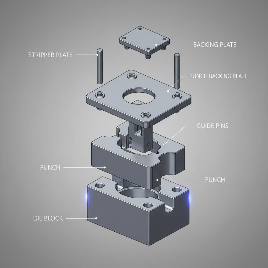
Toisin kuin yksinkertaisemmat muotityypit, joissa saattaa riittää perustavanlaatuinen työntö- ja leikkuumuottijärjestelmä, yhdistelmämuotit integroivat useita toiminnallisia elementtejä yhdeksi yhtenäiseksi järjestelmäksi. Tässä ovat olennaiset komponentit, jotka löydät hyvin suunnitellusta yhdistelmämuotista:
- Vaikutin: Muotin miespuolinen osa, joka laskeutuu materiaalin sisään ja kohdistaa voiman työkappaleen leikkaamiseksi tai muovaukseksi. Valmistetaan yleensä kovettuneesta teräksestä tai volframikarbidista kestävyyden varmistamiseksi.
- Muottilohko: Muotin naispuolinen osa, joka sijaitsee asennuksen alaosassa ja jossa on leikkuureunat sekä ulomman profiilin leikkaamiseen ja valmiiden osien poistoon tarvittavat aukeamat.
- Irrotuslevy: Poistaa levyaineiston työntäjästä jokaisen iskun jälkeen, varmistaen puhtaan erottelun ja estäen aineksen tarttumisen työkaluun.
- Ohjausnastat: Tarkkuusasennuspinnat, jotka sijoittavat aineksen tarkasti ennen leikkaamista, varmistaen yhdenmukaisen sijoittelun osasta toiseen.
- Tukilevyt: Raskaita teräslevyjä, jotka absorboivat ja jakavat leikkausvoimat, joita syntyy käytön aikana, suojaten puristimen pohjaa ja muottikomponentteja.
- Ohjausnivelet: Sovittavat ylä- ja alamosat muottikokoonpanossa, säilyttäen täydellisen rekisteröinnin koko iskukierroksen ajan.
- Painepadit: Pidättävät työkappaleen kiinni leikkaustoimintojen aikana, estäen liikettä, joka voisi vaarantaa mittojen tarkkuuden.
Muottilohkokokoonpanon sisällä
Työkalukiristin vaatii erityistä huomiota, koska sen kautta yhdistyvät monet tarkkuusmekaniikan elementit. Tämä komponentti tarjoaa leikkuureunat tyhjäkuvaukseen samalla kun se tukee läpikuorintapunssien, joilla luodaan sisäisiä piirteitä. Työkalukiristimen aukot on koneistettu erinomaisen tiukkoihin toleransseihin, ja välykset on laskettu tarkasti materiaalin tyypin ja paksuuden perusteella.
Kun tarkastelet yhdistelmätyökalukiristintä, huomaat, että se täyttää kaksi tehtävää. Ensinnäkin se tarjoaa naisellisen leikkuureunan, jota vasten tyhjäkuvaukseen käytetty punssi leikkaa ulkoprofiilin. Toiseksi se sisältää kovettuneita panoksia tai suojaputkia, jotka ohjaavat läpikuorintapunsseja, kun niillä tehdään sisäisiä reikiä. Tämä kaksinkertainen toiminnallisuus mahdollistaa samanaikaiset toiminnot yhdellä iskulla.
Leikkuumuotti sisältää myös poistomekanismit. Jokaisen osan leikkaamisen jälkeen se on poistettava muotin aukeamasta. Jousikuormitettujen poistimien tai positiivisten poistojärjestelmien avulla valmiit osat työnnetään pois työkaluista, mikä mahdollistaa seuraavan kierroksen aloittamisen ilman häiriöitä. Tämä poistotoiminto on ratkaisevan tärkeä johdonmukaisen kierrosajan ylläpitämisessä tuotantoympäristöissä.
Kriittisten kohdistuskomponenttien
Monitoimimuottien tarkkuus riippuu voimakkaasti komponenttien välisestä oikeasta sijoittelusta. Tässä pilotit ovat erityisen tärkeitä. Ennen kuin iskupinnat koskettavat materiaalia, pilottinipat menevät etukäteen leikattuihin reikiin tai sijoittuvat tarkasti materiaalin reunan vastalle, jolloin työkappale saadaan sijoitettua täsmälleen oikeaan paikkaan. Tämä varmistaa, että jokainen osa saa identtisen käsittelyn riippumatta pienistä nauhan syöttövaihteluista.
Ohjauspinnat ja -rengasosat pitävät ylä- ja alapuolisen muottiosan kohdassa koko iskun ajan. Jopa pieni epäkohtasuus voi aiheuttaa epätasaisen leikkaamisen, työkalun ennenaikaisen kulumisen tai mittojen poikkeamia. Korkealaatuiset yhdistelmämuotit käyttävät tarkkuusjyrsittyjä ohjauskomponentteja, joiden välinen varaus on mahdollisimman pieni, jotta poistetaan kaikki sivusuuntainen liike toiminnan aikana.
Kuinka kaikki siis toimii yhdessä todellisessa puristusiskussa? Kuvittele tämä järjestys: ylämuottiosa alkaa laskeutua, ja irrotuslevy koskettaa ensin levyä, kiinnittäen sen tiukasti muottikappaleeseen. Kun puristin jatkaa alaspäin, ohjauspinnat sijoittavat työkappaleen tarkasti paikoilleen. Sitten yhdessä jatkuvassa liikkeessä ulkoprofiili leikataan irti leikkauspistoolilla samalla kun pistopistoolit luovat sisäisiä ominaisuuksia. Materiaali leikataan molemmista suunnista samanaikaisesti, ja voimat ovat tasapainossa, jotta levyn tasaisuus säilyy.
Kun leikkaus on valmis, puristin vaihtaa suuntaa. Poistolevy pitää jätösverkon paikoillaan, kun työntimet vetäytyvät, mikä mahdollistaa valmiin osan siistin erottamisen. Jousikuormitettujen poistimien tehtävä on sen jälkeen työntää valmis komponentti muottiaukosta ulos, ja sykli on valmis toistumaan. Tämä tarkasti koordinoitu sarja tapahtuu murto-osissa sekunnista, mutta jokaisen komponentin on toimittava virheettömästi.
Tämän erottaa siitä, miten muottia käytetään edistävissä leikkausoperaatioissa, se että ei tapahdu asemasta toiseen tapahtuvaa liikettä. Edistävissä muottityökaluissa nauha etenee useiden asemien läpi, ja kussakin pysähdyspaikassa suoritetaan eri operaatioita. Vaikka edistävät muotit ovat erinomaisia monimutkaisten osien valmistukseen, joissa vaaditaan muovausoperaatioita, yhdistelmämuotit tuottavat parempia tuloksia silloin, kun tasaisuus ja piirteiden keskittyminen ovat tärkeimmät tekijät.
Näiden mekaanisten periaatteiden ymmärtäminen selittää, miksi komponenttien laatu ja huolto ovat niin tärkeitä. Kun niin moni eri osa toimii yhdessä merkittävien voimien vaikutuksesta, jopa pieni kulumisilmiö tai asemointivirhe voi vaikuttaa osan laatuun. Tämä tekninen perusta luo pohjan sille, että arvioidaan, mitkä osageometriat todella hyötyvät monitoimimuottiteknologiasta.
Osageometrian soveltuvuus ja suunnittelun näkökohdat
Olet nähnyt, kuinka monitoimimuotit toimivat mekaanisesti, mutta tässä on käytännön kysymys, johon jokainen insinööri joutuu vastaamaan: toimiiko tämä menetelmä todella tietyn osasi tapauksessa? Termiä "yksinkertaisemmat osat" käytetään usein monitoimimuottipainatusmenetelmää käsiteltäessä, mutta sitä harvoin määritellään tarkasti. Muutetaan tämä tilanne.
Kun valmistajat kuvaavat ideaalisia yhdistelmämuottien käyttökohteita, viittaavat ne yleensä tasaisiin tai lähes tasaisiin komponentteihin, joihin vaaditaan leikkausta yhdistettynä sisäisiin porausoperaatioihin. Tällaisia ovat esimerkiksi kierrekannukset, kalvot, tiivisteet, pakningit ja etäisyyspalat – osat, joiden sisäisten ja ulkoisten ominaisuuksien välinen suhde on pysyttävä täysin vakiona. Mukaan lukien Valmistaja , ilmailu-, terveydenhuolto- ja teollisuusalan segmentit määrittelevät usein näitä komponentteja erinomaisen tarkkojen mittojen, keskittäisyyden ja tasaisuuden vaatimusten perusteella, jotta voidaan täyttää tiukat alan sertifikaatiot.
Ideaaliset osageometriat yhdistelmämuoteille
Mitkä siis tarkalleen ottaen tekevät osageometriasta sopivan yhdistelmämuottipainamiseen? Vastaus perustuu useisiin keskeisiin ominaisuuksiin, jotka sopivat yhteen samanaikaisen leikkauksen edut, joita nämä työkalut tarjoavat:
- Pyöreät tasaiset osat keskitetyillä rei’illä: Kierrekannukset, tasaiset renkaat ja etäisyyspalat, joiden halkaisija on noin 6 tuumaa tai vähemmän, edustavat klassista yhdistelmämuottien käyttökohtetta.
- Sähköiset liittimet ja liitinliuskat: Komponentit, joissa vaaditaan tarkkaa reiän ja reunan keskikohdun yhteensovittamista, hyötyvät samanaikaisesta sisäpinnan (ID) ja ulkopinnan (OD) leikkauksesta.
- Ohut materiaali: Osat, jotka leikataan materiaalista, jonka paksuus voi olla jopa 0,0005 tuumaa – missä edistävä metallileikkaus aiheuttaisi käsittelyssä muodonmuutoksia – ovat erinomaisia ehdokkaita.
- Komponentit, joissa vaaditaan tiukkaa keskikohdan yhteensovittamista: Kun piirustuksissa määritellään enimmäiskeskikohdan sallittu poikkeama, yhdistelmätyökalut tuottavat tuloksia, joita peräkkäisillä toimenpiteillä ei voida saavuttaa.
- Tasaiset raakapalat useilla läpikuorituilla ominaisuuksilla: Mikä tahansa geometria, jossa kaikki vaaditut toimenpiteet voidaan suorittaa pelkällä leikkauksella ilman muotoilua tai taivutusta.
- Litiumpioniakkujen ja tarkan kokoonpanon osat: Sovellukset, joissa sekä keskikohdan yhteensovittaminen että tasaisuus ovat kriittisiä suorituskykyvaatimuksia.
Toleranssikyvyt ansaitsevat tässä erityistä huomiota. Yhdistelmämuotit voivat pitää keskikohdan yhteensovittamisen reikien ja ulkoisten profiilien välillä 0,001 tuuman sisällä, kuten ART Metals Group tämä tarkkuustaso on mahdollista, koska kaikki piirteet leikataan samanaikaisesti – osaa ei siirretä asemalta toiselle, joten kertymävirheiden syntymiselle ei ole tilaa.
Kun yhdistelmämuottien käyttö ei ole oikea valinta
Rajoitusten ymmärtäminen on yhtä tärkeää kuin vahvuuksien tunnistaminen. Tietyt osien geometriat eivät yksinkertaisesti sovi yhdistelmämuottien parhaiten suorittamiin tehtäviin. Jos suunnittelusi kuuluu johonkin näistä luokista, progressiivinen märkä progressiivinen muotti tai siirtomuotti on todennäköisemmin parempi vaihtoehto:
- Taivutus- tai muovausoperaatioita vaativat osat: Yhdistelmämuotit ovat erinomaisia leikkaamiseen, mutta eivät muovaukseen. Jos komponenttisi vaatii reunuksia, rippeitä tai muovattuja piirteitä, tarvitset progressiivisen tai siirtomuottimen.
- Syvävetopyrstöt: Mukulamaiset osat, koteloit, tai muut osat, joissa vaaditaan merkittävää materiaalin virtausta muovauksen aikana, eivät voida valmistaa yhdellä yhdistelmämuottien iskulla.
- Monimutkaiset useasta vaiheesta koostuvat geometriat: Osa, joka vaatii peräkkäisiä muotoiluoperaatioita—eli materiaalin on käsiteltävä vaiheittain useassa eri vaiheessa—ei kuulu yhdistetyn työkalun optimaaliseen käyttöalueeseen.
- Suuret osat, joissa on monimutkaisia sisäisiä piirteitä: Vaikka yhdistetyt työkalut suoriutuvat hyvin useista rei'ityksistä, erinomaisen monimutkaiset sisäiset kaaviot saattavat soveltua paremmin etenevän työkalun leikkausmenetelmään, joka voi sisältää useita leikkausasemia.
- Osa, joka vaatii sisäistä kierreporaus- tai kokoonpano-operaatiota: Toissijaiset operaatiot, jotka on suoritettava muotoiluvaiheiden välissä, vaativat etenevän työkalun asemaperusteisen lähestymistavan.
Tässä on käytännöllinen tapa ajatella asiaa: jos osa voidaan valmistaa täysin samanaikaisilla leikkausoperaatioilla ilman muotoilua, yhdistetyn työkalun leikkausmenetelmää kannattaa harkita vakavasti. Heti kun geometria vaatii taivutusta, vetämistä tai vaiheittaista muotoilua, olet siirtynyt sen työkalutyypin parhaan suorituskyvyn ulkopuolelle.
Päätös perustuu lopulta osien vaatimusten sovittamiseen työkalujen ominaisuuksiin. Yhdistelmämuotit tarjoavat vertaamatonta tarkkuutta tasomaisille, vain leikattaville geometrioille – mutta myös vaihtoehtoisten lähestymistapojen valintahetken tunteminen on yhtä arvokasta. Kun sopivat geometriat on määritetty, seuraava looginen kysymys kuuluu: miten yhdistelmämuotit suhteutuvat suoraan eteenpäin siirtyviin ja siirtomuotteihin, kun projektivaatimukset vaihtelevat?
Yhdistetyt vaivutukset verrattuna edistyksellisiin ja siirtovaivutuksiin
Nyt kun tiedät, millaiset geometriat sopivat yhdistelmämuotteihin, nousee esiin suurempi kysymys: miten valita yhdistelmä-, eteenpäin siirtyvät ja siirto-työkalut, kun useita lähestymistapoja voisi teknisesti ottaa käyttöön? Tämä päätös vaikuttaa kaikkeen alkuinvestointiin saakka sekä pitkän aikavälin kustannuksiin osaa kohden. Rakennetaan järjestelmällinen kehys, joka tekee tästä valinnasta selkeän.
Jokainen muottityyppi täyttää erilaisia valmistustarpeita, ja väärän muotin valitseminen tarkoittaa joko liiallista työkalujen kustannuksia tai laadun ja tehokkuuden heikentymistä. Alla oleva vertailu käsittelee keskeisiä tekijöitä, jotka sinun tulee harkita ennen kuin päätät mihin tahansa lähestymistapaan.
| Valintakriteerit | Yhdistelmänärkät | Progressiivinen kuolema | Siirtodieet |
|---|---|---|---|
| Tuotannon määrä | Pieni–keskimäinen (10 000–500 000 vuodessa) | Suuri volyymi (500 000+ vuodessa) | Keskimäinen–suuri (50 000–1 000 000 vuodessa) |
| Osaen kompleksisuus | Yksinkertaiset tasogeometriat ja läpipurskut | Monimutkainen monivaiheinen muovaus ja leikkaus | Suuret osat, joissa useita muovaustoimintoja |
| Toleranssikyky | Erinomainen keskitarkkuus (±0,001") | Hyvä (±0,002"–±0,005") | Hyvä–erinomainen riippuen suunnittelusta |
| Tyypillinen syklin aika | 30–60 iskua minuutissa | 60–1 500 iskua minuutissa | 15–40 iskua minuutissa |
| Alkuperäinen työkalukustannus | Alhaisempi ($5 000–$50 000) | Korkeampi ($50 000–$500 000+) | Korkein ($75 000–$750 000+) |
| Ihanteelliset sovellukset | Pesurit, tiivisteet, sähköiset liittimet | Kiinnikkeet, liittimet, monimutkaiset kokoonpanot | Autoteollisuuden paneelit, suuret kotelot |
Määrän ja monimutkaisuuden päätös matriisi
Miten tiedät, milloin projekti siirtyy yhdestä muottityypistä toiseen? Tilavuus ja monimutkaisuus vaikuttavat yhdessä tähän päätökseen, ja niiden vuorovaikutuksen ymmärtäminen estää kalliita virhepäätöksiä.
Vuotuisilla määrillä alle 50 000 kappaletta ja yksinkertaisilla leikkausvain-geometrioilla yhdistelmämuotit ovat lähes aina taloudellisesti järkeviä. Alhaisempi työkaluinvestointi tuottaa nopeasti hyötyä, ja saat paremman tarkkuuden ilman monimutkaisemman edistävän muottipursotuksen asennusten lisäkustannuksia. Kun osa vaatii vain leikkausta ja reikäystä, miksi maksaisit muotoiluasemista, joita et käytä?
Kun tuotantomäärät nousevat yli 500 000 kappaletta vuodessa ja osat vaativat taivutusta, muotoilua tai useita peräkkäisiä toimintoja, edistävä muottileikkaus ja puristus tulevat houkutteleviksi ratkaisuiksi. Korkeampi alkuinvestointi jakautuu suuremman määrän osien kesken, mikä laskee huomattavasti kappalekohtaista kustannusta. Edistävän puristusmuotin suunnittelu sisältää useita asemoja, joissa suoritetaan eri toimintoja nauhan edetessä, mikä tekee monimutkaisten geometrioiden taloudellisesti kannattavan valmistuksen mahdolliseksi suurilla sarjoilla.
Siirtomuotit muodostavat ainutlaatuisen keskitason ratkaisun. Kun osat ovat liian suuria standardin kelamaisen edistävän leikkausprosessin käsiteltäviksi – ajattele esimerkiksi autoteollisuuden runkopaneelien tai suurten koteloitten valmistusta – siirtopuristus siirtää yksittäisiä levykappaleita asemalta toiselle mekaanisten sormien tai robottijärjestelmien avulla. Tämä menetelmä mahdollistaa merkittävien muotoilutoimintojen suorittamisen osissa, jotka eivät yksinkertaisesti mahdu edistävään muottityöhön.
Harkitse tätä käytännön esimerkkiä: tarvitset vuosittain 100 000 tasaisia kuparikontaktia, joissa on keskitettyjä reikiä, joiden keskittyvyysvaatimus on ±0,001 tuumaa. Yhdistelmämuotit tuottavat kyseisen tarkkuuden kohtuullisella työkalukustannuksella. Kuvittele nyt sama tuotantomäärä, mutta lisättynä taivutus- ja muovausoperaatioilla. Tällöin edistävä leikkausmuottimen käyttö alkaa näyttää järkevemmältä huolimatta korkeammasta työkalukustannuksesta – syklausaikaan liittyvä etu ja muovauskapasiteetti perustelevat kustannusta.
Kustannusanalyysi eri muottityyppien osalta
Alkuperäisten työkalukustannusten ymmärtäminen on vain aloitus. Todellinen taloudellinen kuva muodostuu, kun lasket kokonaiskustannukset kappaleelta odotetun tuotantokauden aikana. Juuri tässä monien hankintapäätösten teko menee pieleen.
Yhdistetyt leikkaustyökalut tarjoavat alhaisimman kustannusasteikon, joka vaihtelee yleensä 5 000–50 000 dollarin välillä riippuen monimutkaisuudesta. Pienemmille ja keskitasoisille tuotantomääriille tämä tarkoittaa kilpailukykyisiä kustannuksia osaa kohden, vaikka tarkkuusetua ei otettaisi edes huomioon. Et maksa muotoiluasemista, monimutkaisista nauhapohjista tai etenevän leikkaustyökalun suunnittelusta, joita yksinkertainen geometriasi ei vaadi.
Etenevät leikkaustyökalut vaativat huomattavasti korkeamman alustavan investoinnin – usein 50 000–500 000 dollaria tai enemmän monimutkaisissa autoteollisuuden sovelluksissa. Niiden erinomainen syklinopeus (joskus yli 1 000 iskua minuutissa) romuttaa kustannukset osaa kohden suurilla tuotantomäärillä. Laskelmat suosivat niitä, kun tuotat vuosittain miljoonia monimutkaisia osia.
Siirtopohjaisen leikkausmuotin käyttö edellyttää korkeinta työkaluinvestointia, mutta se mahdollistaa toimenpiteitä, joita muilla menetelmillä ei voida toteuttaa. Suuret osat, jotka vaativat syvää muotoilua, voimakkaita muotoilutoimenpiteitä tai koontitoimenpiteitä muotissa, oikeuttavat tämän lisähinnan, kun vaihtoehtoiset menetelmät eivät yksinkertaisesti pysty tuottamaan vaadittua geometriaa.
Osan koko muodostaa toisen päätöksen rajan. Yleensä kuuden tuuman mittaiset tai pienemmät osat soveltuvat yhdistelmä- tai edistävään leikkausmenetelmään, kun taas suuremmat osat viittaavat usein siirtopohjaisiin muotteihin. Keloista syötettävän edistävän leikkausmenetelmän fyysiset rajoitukset rajoittavat käytännöllisiä osakokoja, mikä ohjaa suurempia geometrioita kelasta syötettävien osien sijasta tyhjäosista syötettäviin siirtopohjaisiin leikkausoperaatioihin.
Arvioitaessa projektiasi aloita näillä kysymyksillä: Mikä on vuosittainen määrävaatimuksesi? Vaatiiko osasi geometria muovausoperaatioita, vai riittääkö pelkkä leikkaus? Mitkä tarkkuusvaatimukset ovat ehdottomia? Vastaukset sijoittavat sinut selkeästi tähän päätöksentekokehikkoon ja ohjaavat sinut kohti työkaluvalintaa, joka tasapainottaa tarkkuutta, kustannuksia ja tuotantotehokkuutta juuri sinun tarpeitasi vastaavalla tavalla. Kun työkalutyypin valinta on selvinnyt, seuraava tarkasteltava tekijä on yhtä tärkeä: mitkä materiaalit toimivat parhaiten valitulla menetelmällä?
Materiaalien valinta ja yhteensopivuusopas
Olet tunnistanut monitoimityökalut oikeaksi työkaluratkaisuksi osasi geometrian perusteella, mutta tässä on seuraava ratkaiseva kysymys: mitkä materiaalit todella toimivat hyvin tässä sovelluksessa? Useimmat kilpailijat mainitsevat materiaaliyhteensopivuuden ohimennen ilman tarkempia yksityiskohtia. Korjataan tämä antamalla sinulle käytännöllistä ohjeistusta, jota voit soveltaa suoraan seuraavaan projektiisi.
Materiaaliominaisuuksien ja työkalusuunnittelun välinen vuorovaikutus vaikuttaa kaikkeen saavutettaviin tarkkuuksiin asti työkalun käyttöiän suhteen. Näiden suhteiden ymmärtäminen auttaa sinua optimoimaan sekä osien laatu että tuotannon taloudellisuus. Tässä on esitetty, miten yleisimmät metallit suoriutuvat monitoimityökaluoperaatioissa:
| Materiaaliluokka | Sovivuus | Tärkeät huomiot | Tyypilliset sovellukset |
|---|---|---|---|
| Hiiliteräkset | Erinomainen | Ennakoitavat leikkausominaisuudet; standardit leikkausvälistöt toimivat hyvin; kustannustehokas työkalujärjestelmä | Kiekot, kalvot, yleiset teollisuuskomponentit |
| Rosteeton teräs | Hyvä | Edellyttää vankkaa työkalujärjestelmää; työstön kovettuminen edellyttää terävämpiä leikkausreunoja; suurempia leikkausvälistöjä tarvitaan | Lääkintälaitteet, elintarvikkeiden käsittely, korroosionkestävät osat |
| Hopesumeet | Erinomainen | Ideaali sähkökomponentteihin; pehmeä luonne mahdollistaa tiukat tarkkuudet; huomioi porrasmuodostumisen | Sähkökontaktit, virtapalkit, liittimet |
| Messinki | Erinomainen | Erinomainen muovautuvuus; puhtaat leikkausominaisuudet; vähäinen työkalukuluminen | Tarkkuuskiekot, koristekomponentit, liitososat |
| Alumiini | Hyvä | Edellyttää erityisiä leikkausvälistöjä (yleensä suurempia); galling-vaara; pinnoite voi auttaa | Kevyitä komponentteja, elektronisia suojia, lämmönvaihtimia |
Hiiliteräksen edistävän leikkaamisen sovellukset hyötyvät materiaalin suvaitsevasta luonteesta, ja sama pätee myös yhdistelmämuottityöhön. Standardiset alahiuksiset teräkset leikataan siististi ja niiden käyttäytyminen on ennustettavissa, mikä tekee niistä ihanteellisia lähtökohtia uuden työkalujen kehittämisessä. Messinkin edistävä leikkaaminen tarjoaa samankaltaisia etuja – materiaalin erinomainen muovautuvuus johtaa siisteiin reunoihin ja yhtenäisiin tuloksiin yhdistelmäoperaatioissa.
Materiaalin paksuusohjeet
Paksuusalue vaikuttaa merkittävästi yhdistelmämuottien soveltuvuuteen. Vaikka nämä työkalut käsittelevät vaakalaajaa materiaalin paksuusalueita, tietyt paksuusalueet optimoivat samanaikaista leikkaushyötyä, jota etsitte.
Useimmissa sovelluksissa yhdistelmämuotit toimivat parhaiten materiaalin paksuuksilla välillä 0,005–0,250 tuumaa. Tällä alueella tasapainoiset leikkausvoimat, jotka tuottavat erinomaisen tasaisuuden, toimivat suunnitellulla tavalla. Ohuemmat materiaalit (erityissovelluksissa jopa 0,0005 tuumaa) vaativat huolellista poistimen painon säätöä vääristymän estämiseksi käsittelyn aikana. Paksuempia materiaaleja käytettäessä vaaditaan suhteellisesti suurempaa puristimen tonnia ja kestävämpiä työkalukomponentteja.
Tässä on käytännöllinen ohje: kun materiaalin paksuus kasvaa, myös työntimen ja muotin välinen varaus on lisättävä – yleensä laskettuna prosentteina lähtömateriaalin paksuudesta. Malleissa käytetään hiilikteräksestä noin 5–7 %:n varausta kummallekin puolelle. Ruisuteräkselle vaaditaan 6–8 %:n varausta, kun taas pehmeämmät materiaalit, kuten kupari, voivat etenevissä leikkaussovelluksissa toimia 3–5 %:n varauksin.
Kovuus- ja muovautuvuusnäkökohdat
Materiaalin kovuus vaikuttaa suoraan työkalusuunnittelun päätöksiin. Kovemmat materiaalit aiheuttavat suurempia leikkausvoimia ja kiihdyttävät työkalun kuluma-aikaa. Niitä varten tarvitaan myös suurempia työkaluvälejä, jotta työkaluun kohdistuva liiallinen rasitus ja ennenaikainen vikaantuminen voidaan estää.
Kovempien materiaalien, kuten ruostumattoman teräksen tai jousiteräksen, käsittelyssä odota seuraavien määrittelyjä:
- Suuremmat välit: Yleensä 1–2 % suuremmat kuin pehmeän teräksen vastaavat arvot
- Kovemmat työkaluteräkset: D2-, M2-teräkset tai kovametallipäällikkeet leikkausreunoille
- Useammin teroitettavaa: Lyhyempiä välejä huoltokierrosten välillä
- Suurempaa puristusvoimaa: Suurempia voimia tarvitaan materiaalin puhdasta leikkaamista varten
Pehmeämmät ja muovautuvammat materiaalit aiheuttavat erilaisia haasteita. Kupari ja messinki mahdollistavat tarkemmat toleranssit ja aiheuttavat vähemmän työkalujen kulumista, mutta niiden muovautuvuus voi aiheuttaa terävien reunojen muodostumista leikkausreunoille. Materiaali pyrkii liukumaan pikemminkin kuin leikkautumaan siististi, erityisesti jos välykset ovat liian pienet tai leikkausterät ovat tylsistyneet.
Muovautuvuus vaikuttaa myös siihen, miten materiaalit käyttäytyvät samanaikaisessa leikkaustoiminnossa. Erittäin muovautuvat metallit voivat osoittaa enemmän pyöräytystä leikkausreunoilla – pyöristynyttä aluetta, jossa materiaali taipuu ennen leikkautumista. Sovelluksissa, joissa vaaditaan siistejä ja neliömäisiä reunoja, välysten säätäminen ja terävien työkalujen ylläpitäminen ovat olennaisia.
Yksi usein huomioimaton tekijä on materiaalin kovuusaste. Pehmennetyt materiaalit leikataan helpommin, mutta ne voivat tuottaa enemmän teräviä reunoja. Työstökovettuneet tai kovennetut materiaalit leikataan siistimmin, mutta niiden leikkaamiseen vaaditaan suurempi leikkausvoima. Oikean kovuusasteen määrittäminen leikkuutyökaluillesi ja puristusoperaatioillesi voi merkittävästi vaikuttaa sekä osien laatuun että työkalujen kestoon.
Näiden materiaalikohtaisten käyttäytymisten ymmärtäminen mahdollistaa sekä muottisuunnittelun että tuotantoparametrien optimoinnin. Mutta edes paras materiaalivalinta ei kompensoi huonoa huoltotapaa – mikä johtaa keskustelun keskeiseen aiheeseen: työkalujen pitämisessä huippukunnossa.
Huoltovaatimukset ja ongelmanratkaisu
Olet valinnut oikeat materiaalit ja työkalujen lähestymistavan, mutta tässä on realiteettitarkistus: jopa täydellisesti suunnitellut yhdistelmämuotit kulumia ilman asianmukaista huoltoa. Yllättäen tätä keskeistä aihetta ei juurikaan käsitellä useimmissa puristusprosessien resursseissa. Huoltotavat vaikuttavat suoraan siihen, tuottavatko työkalut laadukkaita osia 100 000 vai 1 000 000 kierroksella. Täytetään tämä aukko toimintasuunnitelmallisella huollon ohjeistuksella.
Kuten yksi tarkkuustuottaja huomautti: "Jos et pysty pitämään työkalujasi terävinä, ne eivät mene painokoneeseen eikä sinä tuota leikattuja osia ". Tämä todellisuus pätee yhtä lailla yhdistelmämuotteihin – huolto ei ole vapaaehtoinen, vaan se on välttämätöntä johdonmukaiselle tuotannolle.
Joka kerta, kun leikkuutyökalunsi kulkeutuu puristimesta ulos, tulee noudattaa systemaattista tarkastusprotokollaa. Tässä ovat kriittiset tarkastuspisteet, jotka varmistavat työkalujen suorituskyvyn huippukunnossa:
- Leikkuureunan kunto: Tarkasta työntöpään ja leikkuutyökalun leikkuureunoja sirujen, halkeamien tai näkyvien kulumismallien varalta. Bluntit reunit aiheuttavat teräviä reunavia ja vaativat suurempaa leikkuuvoimaa.
- Välyksen tarkistus: Mitaa työntöpään ja leikkuutyökalun välistä välystä useissa pisteissä. Epätasainen kuluminen aiheuttaa epäyhtenäisiä välyksiä, jotka vaikuttavat osan laatuun.
- Tasaus tarkistukset: Tarkista ohjainpinnan ja -putken sovitus. Liiallinen löysyys osoittaa kulumaa, joka aiheuttaa mittojen poikkeamia ja nopeuttaa työkalun kulumista.
- Jousijännitys: Testaa irrotusjouset ja työntömekanismi. Heikentyneet jouset aiheuttavat epätäydellisen irrottamisen ja osien käsittelyongelmia.
- Voiteluainevaatimukset: Tarkasta ohjauspinnat, liikkuvat komponentit ja kulumislevyt. Oikea voitelu estää tarttumista (galling) ja pidentää komponenttien käyttöikää.
- Ohjauspinnan kunto: Tarkista ohjauspinnat kulumasta tai vaurioista, jotka voivat vaikuttaa osan sijoittelutarkkuuteen.
Terästen teroittamisen aikataulut ja leikkuuterän huolto
Milloin tulisi teroittaa työkaluja? Vastaus riippuu materiaalin tyypistä, tuotantomäärästä ja laatuvaatimuksistanne – mutta odottaminen siihen saakka, kun osat eivät enää läpäise tarkastusta, tarkoittaa, että olette odottaneet liian kauan.
Määrittäkää teroitusväliä iskumäärän perusteella eikä kalenteriajan perusteella. Hiilellä seostettujen terästen käsittelyssä monet teollisuuslaitokset suunnittelevat teroituksen joka 50 000–100 000 iskua. Ruisuteräkset ja kovemmat materiaalit voivat vaatia huomiota jo joka 25 000–50 000 iskua kovemman leikkuuterän kulumatason vuoksi. Seuratkää näitä välejä tarkasti – edistävissä työkalu- ja muottitoiminnoissa säännöllisen huollon ohittaminen johtaa välttämättä ennennäkemättömään käyttökatkokseen.
Nykyiset pinnanhiomakoneet ovat muuttaneet huollon tehokkuutta. DCM Tech mukaan pyörivät pinnanhiomakoneet voivat suorittaa työkalujen teroituksen kolmessa–neljässä tunnissa verrattuna perinteisten koneiden kahdeksaan–kaksitoistaan tuntiin. Tämä aikasäästö kääntyy suoraan nopeammin saavutettaviin toimitusaikoihin ja lisää tuotantokäyttöaikaa.
Hiontaprosessi itsessään vaikuttaa työkalujen kestovuuteen. Pintahionta poistaa kuluneita materiaaleja lämmön tuomatta mukaan, mikä voisi heikentää kovennettuja leikkuureunoja. Yhden työkaluhuoneen koneistajan selityksen mukaan: "Hionnasta saadaan paljon vankempi tuote, koska ei tarvitse tuoda lämpöä hitsaamalla, mikä voi heikentää tarkkaleikkaus-työkalua sen kantamaan paineeseen liittyvistä syistä." Sama periaate pätee myös yhdistelmämuottien huoltoon – uudelleenhionta säilyttää työkalun eheyden paremmin kuin vaihtoehtoiset korjausmenetelmät.
Muottien käyttöiän pidentäminen asianmukaisella hoidolla
Kuluman tunnistaminen ennen kuin se aiheuttaa laatuongelmia erottaa ennakoivan huollon reagoivasta ongelmanratkaisusta. Tässä ovat varoittavat merkit, jotka osoittavat, että työkalujasi tarvitaan huolta:
- Lousun muodostuminen: Leikattujen reunojen karvan korkeuden kasvu viittaa tumpeneviin leikkuureunoihin tai välyksen ongelmiin. Korjaa tämä ennen kuin karvat aiheuttavat alapuolella olevia ongelmia.
- Mittapoikkeama: Kun osat siirtyvät vähitellen sallituista toleransseista, kuluma on todennäköisesti vaikuttanut kriittisiin asennuskomponentteihin tai leikkuureunoihin.
- Kasvanut leikkausvoima: Jos puristusvoiman vaatimukset kasvavat, tylsistyneet leikkuureunat pakottavat materiaalia pikemminkin kuin leikkaavat sitä puhtaasti.
- Epäyhtenäinen osan tasaisuus: Irrotuspaineen ongelmat tai epätasainen leikkuureunan kulumine voivat aiheuttaa osan vääntymisen, jota ei alun perin ollut havaittavissa.
- Epätavallinen melu tai värinä: Toimintää koskevien äänien muutokset viittaavat usein asennusvirheisiin tai komponenttien kulumiseen, mikä edellyttää tutkimusta.
Sopiva huolto pidentää työkalujen käyttöikää merkittävästi samalla kun osien laatu säilyy. Sekä etenevät työkalut että yhdistelmämuotit hyötyvät dokumentoiduista huoltotiedoista, joissa seurataan tehtyjä toimenpiteitä ja niiden vaikutuksia. Tämä tieto auttaa ennustamaan tulevia huoltotarpeita ja optimoimaan teroitustaukoja erityisesti teille tarkoitettuihin sovelluksiin.
Yleisten ongelmien ratkaisua
Kun laatuongelmia ilmenee, systemaattinen vianetsintä mahdollistaa juurisyyn nopean tunnistamisen. Tässä on käytännöllinen opas yleisimpiin yhdistelmämuottiongelmiin:
| Ongelma | Mahdollinen syy | Korjaava toimi |
|---|---|---|
| Liialliset reunusrei'ät | Riittämätön välys tai tylsistyneet leikkuureunat | Tarkista ja säädä välykset; teroita tai vaihda kuluneet komponentit |
| Osan vääristymä | Epäasianmukainen irrotuspaine tai epätasapainoiset leikkausvoimat | Säädä irrotusjousien jännitystä; varmista tasainen painejakauma |
| Mittavaihtelu | Kohdistuksen kulumista tai leikkausreunan heikkenemistä | Tarkista ohjauspinnat ja -putket; tarkastele epätasaista kulumismallia |
| Reikien sijainnin epäjatkuvuus | Ohjauspinnan kulumista tai nauhan syöttöongelmia | Vaihda kuluneet ohjauspinnat; varmista syöttötarkkuus ja nauhan ohjaus |
| Ennenaikainen työkalun rikkoutuminen | Ylä- ja alapuolen muottipuolten välinen epäkohdistuminen | Käytä kohdistusmantelia tornin kohdistuksen tarkistamiseen ja säätämiseen |
DGMF-muottikiinnittimien vianmääritysohjeiden mukaan tornin ja kiinnitysalustan kohdistuksen tarkistaminen säännöllisesti kohdistusmantelin avulla estää epätasaisen kuluman, joka aiheuttaa etenevien työkalujen ja yhdistelmämuottien ennenaikaisen vaurioitumisen. Tämä yksinkertainen toimenpide havaitsee ongelmat ennen kuin ne vahingoittavat kalliita työkaluja.
Kun tyhjäysongelmat jatkuvat, muistetaan, että säädöt tulisi tehdä vähitellen. Jokaisen säädön tulisi mieluiten olla enintään 0,15 mm, jotta ylisäätöä ei tapahdu. Käytä alhaisempaa pistopnopeutta vianetsinnässä komponenttien kuormituksen vähentämiseksi, kunnes on löydetty ongelman juurisyy.
Kun huoltoprotokollat on laadittu, olet valmis pitämään monitoimimuottisi tuottamassa laadukkaita osia jatkuvasti. Ymmärtämisestä, missä näitä työkaluja voidaan hyödyntää tehokkaimmin eri aloilla, avautuu kuitenkin vielä lisää mahdollisuuksia hyödyntää niiden tarkkuusetuja.
Teollisuussovellukset ja autoteollisuuden valmistus
Olet hallinnut yhdistettyjen leikkuutyökalujen tekniset perusteet—nyt tutkitaan, missä näillä työkaluilla on suurin vaikutus todellisessa valmistuksessa. Sähkökontaktit älypuhelimesi sisällä ja tarkkuusrengaslevyt automaalin jarrujärjestelmissä ovat vain muutamia esimerkkejä tuotteista, joiden valmistukseen yhdistetyt leikkuutyökalut hiljaa mahdollistavat päivittäin käyttämiemme tuotteiden tuotannon. Näiden sovellusten ymmärtäminen paljastaa, miksi tietyt teollisuudenalat eivät voi millään tavalla hyväksyä kompromisseja tämän työkalujen valmistustavan tarjoamien tarkkuusetujen osalta.
Autoteollisuuden tarkkuuskomponenttien sovellukset
Kun painat jarrupoljinta, luotat komponentteihin, jotka on leikattu tuhannesosain tuumien tarkkuudella. Autoteollisuuden valmistajat luottavat voimakkaasti yhdistettyihin leikkuutyökaluihin tasaisiin ja tarkkoihin komponentteihin, joissa mitallinen tarkkuus vaikuttaa suoraan suorituskykyyn ja turvallisuuteen. Tarkastele näitä kriittisiä sovelluksia:
- Jarrujärjestelmän sävyt ja renkaslevyt: Näillä komponenteilla on oltava täydellinen tasaisuus ja keskitäys, jotta hydraulisen paineen jakautuminen pysyy tasaisena.
- Vaihteiston eristelevyt: Tiukat paksuustoleranssit estävät vaihteiden löysännyttä liikettä ja varmistavat sileän voiman siirron.
- Polttoainesysteemin tiivisteet: Tarkat tiivistepinnat estävät vuotoja, jotka voivat vaarantaa ajoneuvon turvallisuuden ja päästövaatimusten noudattamisen.
- Sähköinen maadoituskosketus: Yhtenäiset reiän ja reunan välisten suhteiden säilyminen varmistaa luotettavat sähköliitokset koko ajoneuvossa.
- Anturien kiinnitysrenkaat: Tasaiset ja keskitetyt komponentit säilyttävät anturien oikean asennon tarkan lukeman saamiseksi.
Autoteollisuuden laatuvaatimukset tekevät IATF 16949 -sertifiointia välttämättömän vaatimuksen työkaluvalmistajille. Lähteessä Master Products tämä sertifiointi "luo perustan odotettavalle laadulle, kun ulkoistat autoteollisuuden metallipainatusprojektisi", ja sen pääpaino on "virheiden ja tuotantopoikkeamien ehkäisymahdollisuuksissa sekä romun ja jätteen vähentämisessä." Kun valitaan toimittajia autoteollisuuden komponenttien edistävään painatukseen, tämä sertifiointi osoittaa sitoutumista järjestelmälliseen laatujohtamiseen, jota alkuperäisten varusteiden valmistajat (OEM:t) vaativat.
Moderni autoteollisuuden muovaus perustuu yhä enemmän CAE-simulaatioihin (tietokoneavusteinen tekniikka) työkalusuunnittelun optimointiin ennen kuin mitään metallia leikataan. Tämä lähestymistapa tunnistaa mahdollisia ongelmia materiaalin virtauksessa, jännityskeskittymissä ja mitallisessa vakaudessa suunnitteluvaiheessa – säästäen sekä aikaa että työkalukustannuksia. Toimittajat, jotka tarjoavat edistyneitä simulaatiokykyjä yhdessä IATF 16949 -sertifiointinsa kanssa, kuten Shaoyin tarkkuusstanssimuottiratkaisut , voivat nopeuttaa kehityssykliä samalla kun ne varmistavat virheettömät tuotantotulokset.
Sähkö- ja elektroniikkateollisuuden käyttötavat
Jos autoteollisuuden sovellukset vaativat tarkkuutta, sähkö- ja elektroniikkateollisuuden valmistus nostaa vaatimukset täysin toiselle tasolle. Edistävä muovausmuottiprosessi sopii hyvin suurten sarjojen liittimien koteloita ja monimutkaisia päätyosia varten, mutta yhdistelmämuotteja suositellaan edelleen, kun keskittävyys ja tasaisuus ovat ehdottomia vaatimuksia.
Leimattuja sähkökontakteja pidetään ehkä vaativimpana yhdistelmätyökalun sovelluksena. Kuten Composidie selittää, nämä peruskomponentit "toimivat johtimen ja liitoskohdan välisenä rajapintana ja varmistavat luotettavan sähkökontaktin." Mitä tahansa mitallisesti poikkeavaa voi aiheuttaa vastusta, joka synnyttää lämpöä, heikentää signaalia tai johtaa ennenaikaiseen vikaantumiseen.
Kriittisiä elektroniikkasovelluksia ovat:
- Akun liittimet: Litiumioniakkujen kokoonpanoihin vaaditaan tasaisia kontakteja tarkoilla reikäpaikoilla johdonmukaisen virran kulun varmistamiseksi.
- Liitinliittimet: Monopinnallisten liittimien pinnit ja vastapinnit täytyy pitää täsmälleen oikeassa mitallisessa suhteessa luotettavan yhdistämisen varmistamiseksi.
- Maadoituskiekot: EMI-suojaussovelluksissa vaaditaan täydellisiä kosketuspintoja tehokkaan maadoituksen varmistamiseksi.
- Lämmönvaihtimen kiinnityskomponentit: Tasaiset ja tarkasti mitoitut komponentit varmistavat maksimaalisen lämmönsiirron.
- PCB:n kiinnitysetäisyydet: Yhtenäinen paksuus estää levyn jännityksen ja varmistaa asianmukaisen komponenttien välimatkan.
Edistävä leikkausmuottiprosessi on erinomainen monimutkaisten muotoiltujen liittimien tuottamiseen suurissa määrissä, mutta kun sovelluksesi vaatii ainoastaan täysin tasaisia ja tarkasti sijoitettuja piirteitä, yhdistelmämuottaus tuottaa parempia tuloksia alhaisemmin muottikustannuksin.
Ilmailu- ja lääketekniikkasovellukset
Ilmailu- ja lääkintälaiteteollisuus jakavat yhteisen piirteen: epäonnistuminen ei ole vaihtoehto. Molemmat teollisuudenalat määrittelevät materiaalit, prosessit ja toleranssit erinomaisen tarkasti, ja yhdistelmämuotit ovat keskeisessä roolissa näiden alojen vaatimien tarkkojen tasolevykomponenttien valmistuksessa.
Mukaan lukien CEI Precision heidän tiiminsä on 'palvellut käytännössä jokaista alaa, jossa tarkkuus on ehdoton vaatimus, varmistaen, että jokainen ohjelma tuottaa saman korkean tasoiset leikkauslaatut ja yhdenmukaisuuden.' Tarkkuusleikattavia kirurgisia laitteita ja hammashoitoon käytettyjä työkaluja aina polttokennojen ja ilmailukomponenttien osiin saakka monitasoleikkauskyvyt kattavat sovellukset, joissa mitallinen tarkkuus vaikuttaa suoraan ihmisten turvallisuuteen.
Ilmailusovellukset sisältävät usein eksotisia materiaaleja – esimerkiksi titaania, Inconelia ja erikoisvalikoituja seoksia, jotka edellyttävät kestävää työkalujärjestelmää ja tarkkaa prosessin säätöä. Lääketieteelliset laitteet vaativat usein ruostumatonta terästä tai titaania sisältäviä komponentteja, joiden on täytettävä biokompatibilisuusvaatimukset samalla kun ne säilyttävät tiukat mitalliset määrittelyt. Molemmissa tapauksissa monitasoleikkausmuottien samanaikainen leikkaustoiminto tarjoaa tämän vaativan sovellusten vaatiman keskitetyyden ja tasaisuuden.
Monikertaisesti toimiva monitasoleikkaustyökalujärjestelmä suurille tuotantomääriälle
Mitä tapahtuu, kun osan geometria sopii yhdistelmämuottipursotukseen, mutta tuotantomäärät ovat lähellä jatkuvan pursotuksen aluetta? Moniiskuun yhdistelmämuottityökalut täyttävät tämän aukon yhdistämällä samanaikaisen leikkaamisen tarkkuusetuja korkeampiin tuotantonopeuksiin.
Moniiskuun konfiguraatiossa nauha etenee yhdistelmämuotin läpi useita kertoja, ja jokainen isku tuottaa valmiin osan eri kohdasta nauhaa. Tämä menetelmä moninkertaistaa tuotannon ilman, että menetetään yhdistelmämuottien arvokkaita keskitettyys- ja tasaisuusetuja. Se on erityisen tehokas pienille osille, joissa useita kammioita voidaan sijoittaa yhden muotin pohjapinta-alalle.
Jatkuvan pursotuksen prosessi säilyy edelleen parempana vaihtoehtona todella monimutkaisille osille, jotka vaativat muotoiluoperaatioita, mutta moniiskuun yhdistelmämuottityökalut tarjoavat houkuttelevan keskitien. Saavutat lisääntyneen tuottavuuden säilyttäen samalla tarkkuusominaisuudet, joita peräkkäisillä operaatioilla ei yksinkertaisesti saada aikaan.
Olipa sovelluksenne auton jarrujärjestelmä, tarkat sähköiset liitokset tai elämän kannalta kriittiset lääketieteelliset laitteet, yhdistelmämuotit tarjoavat mitattavia laatu-etuja silloin, kun tasaisuus ja keskikkoisuus ovat tärkeimmät tekijät. Näiden teollisuussovellusten ymmärtäminen auttaa teitä tunnistamaan mahdollisuudet, joissa tämä muottiratkaisu parantaa valmistustuloksianne – ja antaa teille perustan tehdä informoituja päätöksiä seuraavan leimausprojektinne arvioinnissa.
Oikean yhdistelmämuotin ratkaisun valinta projektillenne
Olette tutustunut teknisiin yksityiskohtiin, ymmärtäneet materiaaliharkinnat ja tutkineet teollisuussovelluksia – mutta nyt on totuuden hetki. Kuinka arvioida itse asiassa, sopivatko yhdistelmämuotit juuri teidän tiettyyn projektinne? Ja kun olette tehneet tämän päätöksen, kuinka löytää muottikumppani, joka kykenee toimittamaan halutut tulokset? Muutetaan kaikki oppimanne käytännölliseksi päätöksenteon kehykseksi.
Erona onnistuneen muovausprojektin ja kalliin virheen välillä usein kysymys siitä, esitetäänkö oikeat kysymykset oikeaan aikaan. Mukaan lukien teollisuuden asiantuntijat , "Ennen kuin voit arvioida mahdollisia toimittajia tehokkaasti, sinun on oltava täysin selvillä omien projektisi vaatimuksista. Perusteellinen sisäinen arviointi estää väärinkäsitykset ja varmistaa, että vertaat toimittajia oikeiden kriteerien perusteella."
Yhdistelmämuottiprojektisi tarkistuslista
Ennen kuin otat yhteyttä mihinkään toimittajaan, käy läpi tämä vaiheittainen arviointiprosessi. Jokainen kysymys perustuu edelliseen ja ohjaa sinut selkeään 'kyllä' tai 'ei' -päätökseen yhdistelmämuottityökalujen suhteen:
- Määritä osasi geometria täysin. Onko komponenttisi tasomainen tai melko tasomainen? Vaatii se vain leikkaus- ja reiäntekooperaatioita, vai tarvitaanko muotoilua? Jos taivutusta tai syvävetoa tarvitaan, yhdistelmämuotit eivät ole ratkaisu – harkitse sen sijaan etenevän muotin tai siirtomuotin käyttöä.
- Dokumentoi kriittiset tarkkuusvaatimukset. Mitkä keskittävyysvaatimukset on saavutettava? Jos reiän ja reunan välisten suhteiden on pysyttävä ±0,001 tuuman tarkkuusalueella, yhdistelmämuotit tarjoavat tämän tarkkuuden luonnollisesti. Vapaimmat toleranssit voivat mahdollistaa laajemman valikoiman muottivaihtoehtoja.
- Laske vuosittaiset tuotantomäärävaatimuksesi. Tuotatko 10 000 osaa vai 10 miljoonaa osaa? Yhdistelmämuotit toimivat erinomaisesti pienestä keskimittaiseen tuotantomäärään (noin 10 000–500 000 osaa vuodessa). Korkeammat tuotantomäärät voivat perustella edistävän muottitekniikan käytön, vaikka sen alkuinvestointi olisi suurempi.
- Määritä materiaalin tyyppi ja paksuus. Varmista, että käyttämäsi materiaali kuuluu yhdistelmämuottien käsittelykykyyn. Hiiliteräkset, messingi, kupari-seokset ja alumiini toimivat kaikki hyvin. Kirjaa tarkat paksuus- ja kovuusmäärittelyt, jotta toimittajat voivat antaa tarkat tarjoukset.
- Tunnista toissijaisia käsittelyvaiheita vaativat vaatimukset. Tarvitsevatko osat lämpökäsittelyä, pinnoitusta, teräspäiden poistoa tai kokoonpanoa? Kumppanit, jotka tarjoavat näitä arvolisäpalveluita sisäisesti, yksinkertaistavat huomattavasti toimitusketjuasi.
- Määritä prototyyppi- ja sarjatuotantoaika. Milloin tarvitsette ensimmäiset tuotteet? Mikä tuotantotyökalujen valmisteluaika on hyväksyttävissä? Nopea prototyyppivalmistus – joka on joskus saatavilla jo viidessä päivässä – voi merkittävästi kiihdyttää kehitysprosessiannne.
- Määrittele laatuvarmennusten vaatimukset. Vaatiiko teidän alanne tiettyjä sertifikaatteja, kuten ISO 9001 tai IATF 16949? Poissulje toimittajat, jotka eivät pysty tarjoamaan vaadittuja asiakirjoja ennen kuin käytätte aikaa yksityiskohtaisten keskustelujen tekemiseen.
Tämä systemaattinen lähestymistapa varmistaa, että olette harkinneet kaikki kriittiset tekijät ennen toimittajien kanssa aloitettavaa yhteistyötä. Se tarjoaa myös kumppaneille yksityiskohtaiset määrittelyt, joiden perusteella he voivat antaa tarkat tarjoukset ja realistiset aikataulut.
Työkalujen toimittajien arviointi
Kun projektin vaatimukset on dokumentoitu, olette valmiita arvioimaan mahdollisia toimittajia. Mutta mitä erottaa riittävät toimittajat todellisista valmistusyhteistyökumppaneista? Arvioi näitä olennaisia kykyjä hintaa per osa laajemmin:
Teknisen asiantuntemuksen merkitys on suurempi kuin saattaisi ensin tuntua. Parhaat leimauslaitteiden toimittajat ovat todellisia kumppaneita, jotka tarjoavat insinööritukea, ei ainoastaan valmistuskapasiteettia. Heidän varhainen osallistumisensa valmistettavuuden suunnittelua (DFM) koskeviin tarkasteluihin voi johtaa merkittäviin kustannussäästöihin ja vankempiin osien suunnitelmiin. Kysy mahdollisilta kumppaneilta heidän insinööriresursseistaan ja siitä, ovatko he valmiita yhteistyöhön suunnitelman optimoinnissa ennen työkalujen valmistusta.
Laatujärjestelmät tarjoavat varmuuden. Kuten alan ohjeet huomauttavat: "Vankka laatujohtamisjärjestelmä (QMS) on ehdoton vaatimus. Se on perusta sille, että saat johdonmukaisia ja luotettavia osia, jotka täyttävät määrittelysi." Sertifikaatit, kuten ISO 9001, edustavat kolmannen osapuolen vahvistusta toimittajan sitoumuksesta laatuprosesseihin.
Nopea prototyypitys kiihdyttää kehitystä. Mahdollisuus tuottaa prototyyppiosia nopeasti – joskus päivissä eikä viikoissa – mahdollistaa suunnitelmien validoinnin ennen tuotantotyökalujen käyttöönottoa. Mukaan lukien valmistuksen asiantuntijat , prototyypitys on "kriittinen testausvaihe, jossa ideat muokataan, hioon ja vahvistetaan valmistusta ja markkinamenestystä varten." Kavereilla, joilla on nopea prototyypityskyky, voit tunnistaa ongelmia varhaisessa vaiheessa, kun muutokset ovat edelleen halpoja.
Ensimmäisen kerran hyväksyttyjen osien osuus paljastaa prosessin kypsyyden. Arvioidessasi toimittajia kysy heiltä ensimmäisen kerran hyväksyttyjen osien osuutta vastaavissa projekteissa. Esimerkiksi 93 %:n ensimmäisen kerran hyväksyttyjen osien osuus osoittaa vankkoja prosesseja, jotka johdonmukaisesti tuottavat määritelmien mukaisia osia ilman toistuvia iterointeja. Tämä mittari vaikuttaa suoraan aikatauluusi ja kokonaishankintakustannuksiisi.
Ymmärtäminen siitä, mikä on ohitusreikojen (bypass notches) tarkoitus leikkausmuoteissa ja vastaavissa teknisissä yksityiskohdissa, erottaa tietäväiset toimittajat tilausten vastaanottajista. Kaverit, jotka pystyvät keskustelemaan näistä hienovaraisista seikoista, osoittavat sen asiantuntemuksen, jota tarvitaan ongelmien selvittämiseen ja tuotantoprosessin optimointiin.
Suunnittelusta tuotantoon -kyvyt tehostavat toimitusketjuasi. Toimittajat, jotka tarjoavat kattavia palveluita—alkaen alun perin muottisuunnittelusta ja päättyen suurteholliseen valmistukseen—poistavat koordinaatiosta aiheutuvat vaikeudet. Yhteistyö yhden kumppanin, kuten Shaoyin muottisuunnittelun ja valmistuksen tiimin kanssa, joka hallinnoi koko prosessia, vähentää siirtovirheitä ja vastuun jakautumisen aukkoja.
Ota huomioon myös kapasiteetti ja laajennettavuus. Voiko toimittaja täyttää nykyiset volyymivaatimuksesi ja sopeutua kasvuun tulevaisuudessa? Kumppanit, jotka tarjoavat varastonhallintajärjestelmiä ja joustavia aikataulutuksia, auttavat sinua ylläpitämään tuotantovirtaa ilman liiallista varastoitua tavaraa.
Ideaalinen yhdistelmämuottien kumppani yhdistää tarkkuusmuottien asiantuntemusta insinöörituen, nopean prototyyppivalmistuksen mahdollisuuden ja todistetusti laadukkaat laatuohjelmat—muuntaen eritelmäsi tuotantovalmiiksi osiksi, jotka täyttävät vaatimukset jo ensimmäiseltä tuotantokerralta.
Valintaprosessi päättyy lopulta siihen, että löydät toimittajan, jonka kyvyt vastaavat tarkkoja tarpeitasi. Yksinkertaisen geometrian ja kohtalaiset tuotantomäärät vaativat prog-muottiprojekti ei vaadi samaa kumppania kuin monimutkainen muotti- ja leikkausohjelma, joka palvelee autoteollisuuden alkuperäisvalmistajia (OEM). Sovita kumppanin vahvuudet projektin vaatimuksiin, tarkista heidän aiempi suorituskykynsä samankaltaisissa sovelluksissa ja varmista selkeät viestintäkanavat ennen sitoumusta.
Tutkitpa ensimmäistä kertaa yhdistelmämuotteja tai optimoit jo olemassa olevaa leikkausohjelmaasi, periaatteet pysyvät samoina: määritä vaatimukset huolellisesti, arvioi kyvyt systemaattisesti ja valitse kumppaneiksi ne, jotka osoittavat sekä teknistä osaamista että sitoutumista sinun menestykseesi. Yhdistelmämuottien tarjoamat tarkkuusedut saavutetaan vain silloin, kun kaikki elementit – muottisuunnittelusta tuotantoon ja huoltoon – ovat linjassa laatuasiavoitteesi kanssa.
Usein kysytyt kysymykset yhdistelmämuoteista
1. Mikä on ero yhdistelmämuotin ja yhdistelmämuotin välillä?
Yhdistelmämuotit suorittavat ainoastaan leikkaustoimintoja – tyhjennystä ja rei’itystä – samanaikaisesti yhdellä puristuspulssilla. Yhdistelmämuotit puolestaan suorittavat sekä leikkaus- että muovausoperaatioita yhtä aikaa. Tämä tarkoittaa, että yhdistelmämuotit ovat erinomaisia litteiden osien valmistukseen, joissa vaaditaan erinomaista keskittäisyyttä ja tasaisuutta, kun taas yhdistelmämuotit voivat tuottaa osia, joissa vaaditaan taivutuksia tai muotoilua lisäksi leikkaukseen. Sovelluksissa, joissa vaaditaan tiukkoja sijaintitoleransseja reikien ja reunien välille ilman muovausvaatimuksia, yhdistelmämuotit tarjoavat tarkkuutta, jota yhdistelmämuotit eivät pysty saavuttamaan.
2. Mikä on ero yhdistelmämuotin ja edistävän muotin välistä leikkausmenetelmässä?
Yhdistelmämuotit suorittavat kaikki leikkausoperaatiot samanaikaisesti yhdellä iskulla yhdessä asemassa ja tuottavat valmiita osia erinomaisella keskittyvyydellä ja tasaisuudella. Edistävät muotit siirtävät materiaalia useiden asemien läpi ja suorittavat eri operaatioita kussakin pysähdyskohdassa. Vaikka edistävät muotit soveltuvat suurimittaisiin, monimutkaisiin osiin, joissa vaaditaan muotoiluoperaatioita, yhdistelmämuotit tarjoavat paremman tarkkuuden yksinkertaisemmille tasogeometrioille alhaisemmin työkalukustannuksin. IATF 16949 -sertifioituja toimittajia, kuten Shaoyia, optimoi molempia menetelmiä CAE-simulaatioiden avulla virheettömien tulosten saavuttamiseksi.
3. Mitkä osatyypit soveltuvat parhaiten yhdistelmämuottipursotukseen?
Yhdistelmämuotit toimivat parhaiten tasaisille komponenteille, joissa vaaditaan leikkausta sisäisellä rei'ityksellä – esimerkiksi kierukkarenkaat, kalvot, sähkökontaktit, tiivistimet ja tarkkuusrenkaat, joiden halkaisija on enintään noin 6 tuumaa. Osat, joissa vaaditaan tiukkoja keskittävyystoleransseja (±0,001 tuumaa) reikien ja ulkoisten profiilien välillä, ovat tämän muotin ideaalisia käyttökohteita. Kuitenkin taivutukseen, syvään muotoiluun tai monivaiheiseen monimutkaiseen muotoiluun tarvittavat komponentit eivät sovi tähän menetelmään, vaan niitä varten tulisi käyttää etenevää muottia tai siirtomuottia.
4. Kuinka yhdistelmämuotteja huolletaan optimaalisen suorituskyvyn saavuttamiseksi?
Määritä terävöityssuunnitelmat iskumäärän perusteella eikä kalenteriaikaa käyttäen—yleensä joka 50 000–100 000 iskua hiilikteräkselle. Säännöllisten tarkastusten yhteydessä on tarkistettava leikkuureunan kuntoa, varavaraus, kohdistuskomponentit, jousijännitys ja voitelu. Tarkkaile varoitusmerkkejä, kuten teräspientä muodostumista, mittojen poikkeamia ja leikkuuvoiman kasvua. Nykyaikaiset pintahiomakoneet voivat suorittaa työkalujen terävöityksen 3–4 tunnissa, mikä vähentää käytöstäpoikkeamia ja pidentää muottien käyttöikää merkittävästi.
5. Mitkä materiaalit soveltuvat parhaiten yhdistelmämuotteihin?
Hiiliteräkset tarjoavat erinomaisen yhteensopivuuden ja ennustettavan leikkauskäyttäytymisen. Messingi- ja kuparialiukiot ovat ideaalisia sähkökomponentteihin, mikä mahdollistaa tarkat toleranssit ja puhtaan leikkauksen. Ruostumattomat teräkset vaativat kestävää työkaluutta ja suurempia välejä työstön kovettumisen vuoksi. Alumiini vaatii erityisiä välejä, jotta pinnan tarttuminen (galling) voidaan estää. Materiaalin paksuus vaihtelee yleensä 0,005–0,250 tuuman välillä, ja välit lasketaan prosentteina lähtöaineen paksuudesta materiaalin kovuuden ja muovautuvuuden perusteella.