 Petits lots, altes estàndards. El nostre servei d'prototipatge ràpid fa que la validació sigui més ràpida i fàcil —

El tall personalitzat en fulla de metall desmitificat: mètodes, costos i selecció de partner
Comprendre el tall personalitzat de fulls de metall i per què és important
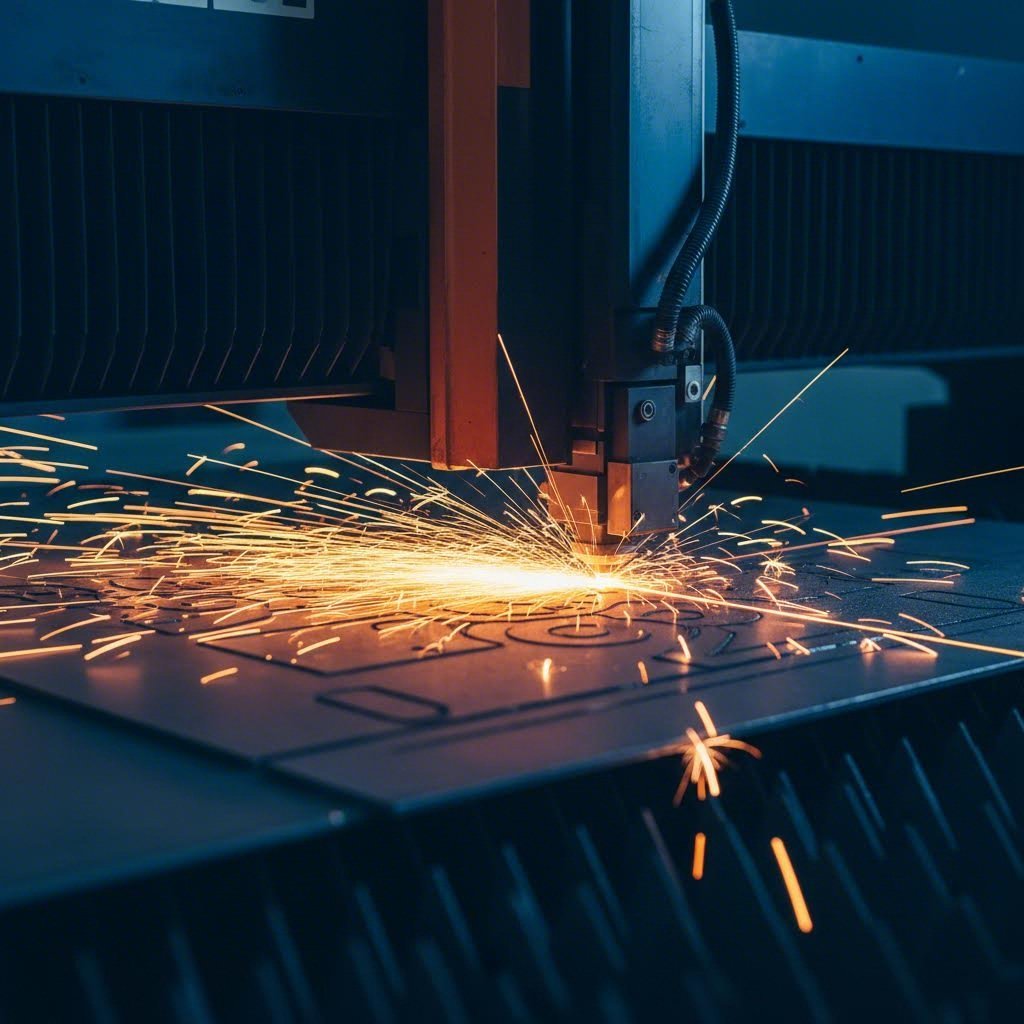
Quan necessiteu un component metàl·lic que s’ajusti exactament a les vostres especificacions, les formes estàndard en estoc simplement no serveixen. Aquí és on entra en joc el tall personalitzat de fulls de metall. Aquest procés especialitzat de fabricació metàl·lica transforma fulls plans de metall en peces de precisió adaptades als requisits únics del vostre projecte. Sigui que esteu desenvolupant un prototip per a una aplicació aeroespacial o produint suports per al muntatge automobilístic , aquest procés ofereix les dimensions, formes i característiques exactes que exigeix el vostre disseny.
Però aquí rau el repte: la majoria de recursos en línia sobre aquest tema es centren massa en la venda de serveis, en lloc d’explicar realment el procés. Us quedeu amb dubtes sobre com funciona tot, quin mètode s’adapta millor a les vostres necessitats i si el tall personalitzat és, efectivament, adequat per al vostre projecte. Aquesta guia canvia aquesta situació oferint-vos els coneixements fonamentals necessaris per prendre decisions informades.
Què fa que el tall de fulls de metall sigui personalitzat
Així doncs, què separa el tall personalitzat d'agafar una fulla de metall estàndard directament de l'estanteria? Es redueix a la precisió i la personalització. Les fulles de metall estàndard arriben en mides, gruixos i formes prèviament definits. Una fulla d'acer típica pot mesurar 4 peus per 8 peus amb un gruix de calibre 16. Aquestes opcions disponibles comercialment funcionen bé per a aplicacions generals com panells de sostre o sistemes de conductes bàsics.
El tall personalitzat, en canvi, comença amb el vostre fitxer de disseny i acaba amb peces que coincideixen exactament amb les vostres especificacions. El procés utilitza tècniques de tall avançades com el tall làser, el tall per plasma o el tall per jet d'aigua per assolir dimensions precises que les opcions estàndard simplement no poden acomodar. Vostè especifica el material, el gruix, la forma i fins i tot forats o patrons intrincats. Penseu en senyals de metall personalitzades amb logotips detallats, suports complexos amb forats de muntatge específics o envolvents amb patrons de ventilació precisos.
Aquest nivell de personalització esdevé essencial quan el vostre projecte requereix:
- Dimensions no estàndard que no coincideixen amb les mides disponibles en estoc
- Formes complexes, corbes o tallats interiors
- Toleràncies ajustades per a muntatges mecànics
- Tipus específics de metalls triats per a característiques de rendiment concretes
- Formes metàl·liques personalitzades dissenyades per a requisits funcionals únics
De la matèria primera a peces de precisió
Imagineu-vos començar amb una planxa d'alumini plana i acabar amb un component de xassís tallat amb precisió, preparat per al muntatge automotriu. Aquesta transformació té lloc mitjançant un procés de fabricació cuidadosament controlat. Primer, es selecciona el material adequat segons els requisits del vostre projecte en termes de resistència, pes i resistència a la corrosió. A continuació, la tecnologia de tall converteix el vostre disseny digital en realitat física amb una precisió remarcable.
Els sectors que depenen d’aquest procés abasten gairebé tots els àmbits de la fabricació moderna:
- Automòbil: Panells de carroceria, suports, components de xassís i escuts tèrmics que requereixen un ajust precís i integritat estructural
- Aeronàutica: Parts d'alt rendiment conformades segons especificacions exactes minimitzant alhora el pes
- Electrònica: Recobriments i carcasses que protegeixen els components mentre acomoden ports, ventilació i requisits de muntatge
- Construcció: Elements arquitectònics, suports estructurals i components especialitzats per a la construcció
- Senyalització: Senyals metàl·liques personalitzades, panells decoratius i elements de marca amb dissenys intrincats
Cadascun d'aquests sectors exigeix una precisió que les formes estàndard no poden oferir. Quan un component ha de complir especificacions exactes i suportar condicions operatives exigents, el tall personalitzat esdevé no només una opció sinó una necessitat. La clau consisteix a comprendre quin mètode de tall, material i especificacions s'ajusten a la seva aplicació concreta, temes que explorarem en les seccions següents.
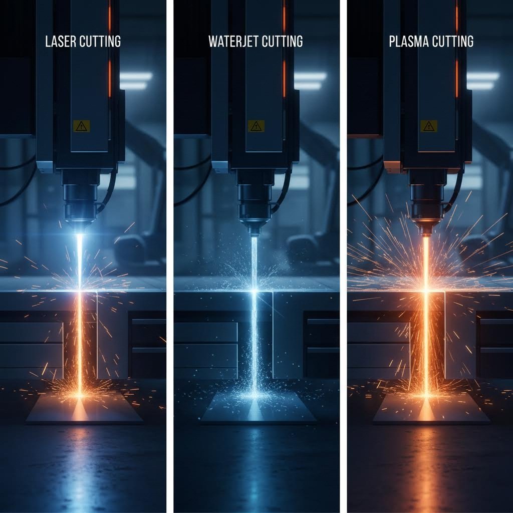
Mètodes de tall comparats: des del làser fins al jet d'aigua
Us pregunteu com retallar làmines metàl·liques per al vostre projecte? La resposta depèn completament del material, dels requisits de gruix i de les necessitats de precisió. Cada tecnologia de tall aporta avantatges diferents, i triar la incorrecta us pot costar milers d'euros en material malgastat i treballs de reforma. Analitzem els quatre mètodes principals perquè pugueu associar la tecnologia adequada a la vostra aplicació específica.
Tall làser per a una precisió extrema
Quan el vostre projecte exigeix una precisió quirúrgica i vores netes, el tall làser ho ofereix. Aquest mètode concentra un raig intens de llum per fondre, cremar o vaporitzar el material al llarg d'una trajectòria precisament definida un tallador làser de fibra pot assolir toleràncies tan ajustades com ±0,05 mm fins a ±0,1 mm, cosa que el converteix en l'opció preferida per a dissenys intrincats i detalls fins.
Què fa que el tall làser es distingeixi en treballs de precisió?
- Vores excepcionalment netes que sovint no requereixen cap acabadat secundari
- Amplada petita de querfa (el material eliminat durant el tall), permetent un encaixat més ajustat de les peces
- Capacitat per tallar forats petits amb diàmetres iguals o més petits que el gruix del material
- Cantonades esmolades i patrons intrincats impossibles amb altres mètodes
El tall làser és excel·lent per a fulls primes, normalment amb millor rendiment en materials d’un gruix inferior a 25 mm. Per a carcasses electròniques, components de dispositius mèdics o qualsevol aplicació que requereixi detalls fins, el tall làser ofereix una capacitat sense comparació. Tanmateix, crea una zona afectada per la calor que pot alterar les propietats del material proper al tall, un aspecte a considerar en aplicacions sensibles a la calor.
Quan el tall per hidroerosió supera el làser
Imaginem un escenari: cal tallar components aeronaútics de titani on qualsevol deformació tèrmica és inacceptable. O potser esteu treballant amb vidre, pedra o materials compostos que els làsers simplement no poden tractar. En aquests casos, el tall per hidroerosió esdevé imprescindible.
La tecnologia d’hidroerosió utilitza un raig d’aigua a alta pressió barrejat amb partícules abrasives per erosionar i tallar gairebé qualsevol material. El el mercat del tall per jet d'aigua preveu superar els 2.390 milions de dòlars el 2034 , reflectint la seva creixent importància en la fabricació de precisió.
Les principals avantatges inclouen:
- Zona lliure d'afectació tèrmica: Cap deformació, endureïment ni distorsió tèrmica
- Versatilitat del material: Talla metalls, pedra, vidre, materials compostos, cautxú i més
- Capacitat per a materials gruixuts: Talla eficaçment materials fins a 200 mm o més
- Toleràncies de precisió: Assoleix ±0,1 mm fins a ±0,25 mm segons el material i el gruix
La contrapartida? El tall per jet d'aigua és més lent que els mètodes de plasma o làser, i els costos operatius solen ser més alts. Però quan no es pot córrer el risc de danys per calor o cal tallar materials no metàl·lics, el tall per jet d'aigua es converteix en l'única opció viable.
Tall per Plasma per Velocitat i Metalls Gruixuts
Necessiteu tallar ràpidament i de manera econòmica una placa d'acer d'una polzada? El tall per plasma domina aquest àmbit. El procés utilitza un arc elèctric i gas comprimit per crear un raig de plasma d'alta temperatura que fon i elimina metalls conductors amb una velocitat impressionant.
Aquesta tecnologia de tall metàl·lic destaca quan:
- Es treballa amb metalls conductors gruixuts (acer, aluminio, coure) superiors a 12 mm
- La velocitat és més important que la precisió ultrafina
- Les restriccions pressupostàries fan que el tall làser sigui prohibitivament costós
- Aplicacions en fabricació d’acer estructural, equips pesats o construcció naval
El plasma assolir toleràncies d’aproximadament ±0,5 mm a ±1,5 mm, més amplades que el làser o el tall per aigua, però totalment acceptables per a aplicacions estructurals. La qualitat del tall requereix més treball de acabat comparat amb el tall làser, però per al processament de metall gruixut, el plasma ofereix el millor equilibri entre velocitat i eficiència de cost.
Aplicacions de router CNC
Tot i que els mètodes tèrmics i de tall per aigua dominen el treball del full metàl·lic, les màquines CNC router tenen aplicacions especialitzades. Aquests sistemes de tall mecànic utilitzen eines rotatives per eliminar material i destaquen amb metalls més tous com l'alumini, especialment quan es necessiten operacions combinades de tall i fresat. Una configuració CNC router pot crear característiques que els mètodes de tall pur no poden assolir, com ara butxaques, canals i contorns complexos en 3D.
Comparació dels mètodes de tall en un cop d'ull
La selecció del mètode adequat requereix sospesar diversos factors al mateix temps. Aquesta taula comparativa reuneix les especificacions clau:
| Factor | Tall Llàser | Tall per Jet d'Aigua | Tall per Plasma |
|---|---|---|---|
| Tolerància de precisió | ±0,05 mm fins a ±0,1 mm | ±0,1 mm a ±0,25 mm | ±0,5 mm a ±1,5 mm |
| Interval d'espessor del material | Fins a 25 mm (òptim sota 12 mm) | Fins a 200 mm o més | Fins a 50 mm o més (òptim per sobre de 12 mm) |
| Zona afectada per la calor | Petit però present | Cap | Gran |
| Qualitat del tall | Excel·lent, gairebé no cal cap acabadat | Bo, lleu textura provocada per l'abrasiu | Més rugosa, sovint requereix desbarbat |
| Velocitat de tall | Ràpid per a materials prims | Més lent que els mètodes tèrmics | El més ràpid per a metalls gruixuts |
| Millors aplicacions | Fulls prims, dissenys intrincats, electrònica, dispositius mèdics | Materials sensibles a la calor, no metàl·lics, aeroespacial, materials gruixuts | Acer gruixut, fabricació estructural, equipament pesant |
| Cost relatiu | Moderat a Alt | La més alta | El més baix |
L'elecció adequada depèn finalment de tres preguntes clau: Quin material esteu tallant? Quant de gruix té? Quina precisió exigeix la vostra aplicació? Per a fulls d'alumini primes que requereixen talls intrincats, el tall amb làser ofereix resultats òptims. Per a acer estructural gruixut, el plasma ofereix una velocitat i valor insuperables. Per a components aerospacials sensibles a la calor o materials no metàl·lics, el tall amb jet d'aigua és l'únic mètode amb aquesta capacitat.
Moltes tallers professionals de fabricació mantenen diverses tecnologies de tall perquè cap mètode únic cobreix totes les aplicacions. Comprendre aquestes diferències us permet especificar el procés adequat per al vostre projecte i comunicar-vos eficaçment amb el vostre soci de fabricació. Un cop esclarida la selecció del mètode de tall, la següent decisió crítica consisteix a triar el material adequat per a les vostres necessitats específiques.
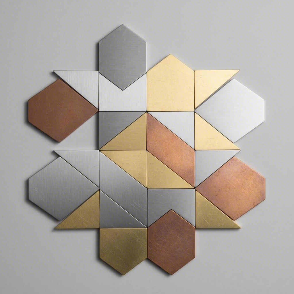
Triar el metall adequat per a projectes de tall personalitzats
Heu seleccionat el vostre mètode de tall, però aquí hi ha el detall: ni tan sols el tallador làser més avançat pot compensar l'elecció del material incorrecte. El metall que seleccioneu condiciona fonamentalment tot, des dels paràmetres de tall fins al rendiment final de la peça. Sigui que estigueu fabricant suports aeronaútics lleugers o accessoris marins duradors, la selecció del material determina l'èxit o el fracàs abans que es produeixi el primer tall.
La majoria de recursos de fabricació passen per alt la selecció de materials, deixant-vos endevinar quina aliatge s'adapta a la vostra aplicació. Canviem això explorant les propietats, els compromisos i les aplicacions pràctiques dels metalls més habituals que es tallen.
Alumini vs Acer per al vostre projecte
Aquesta comparació representa el punt de decisió més freqüent per a projectes personalitzats de tall de xapa metàl·lica tots dos materials dominen la indústria de la fabricació, però compleixen funcions clarament diferents.
Xapa d'alumini ofereix una relació resistència-pes excepcional. Amb aproximadament un terç del pes de l'acer, una làmina d'alumini es converteix en la tria obvia quan la reducció de pes és fonamental. Penseu en les cobertes d'aeronaus, els panells de carroceria d'automòbils i les carcasses d'equipaments portàtils. Aquest material ofereix, a més, una resistència natural a la corrosió, formant una capa protectora d'òxid quan entra en contacte amb l'aire. Per a senyalització exterior, acabats marins i aplicacions arquitectòniques, aquesta característica autorprotegida elimina la necessitat de revestiments protectors.
No obstant això, l'alumini és més car per lliura que l'acer al carboni i té una resistència a la tracció inferior. També és més fàcil de ratllar i pot ser difícil de soldar sense equipament especialitzat.
Placa i làmina d'acer comptador de productes amb una resistència superior i una elevada relació qualitat-preu. L'acer al carboni ofereix una resistència a la tracció més elevada a un cost material més baix, cosa que el fa ideal per a aplicacions estructurals, equips pesats i components portants. La contrapartida? L'acer pesa significativament més i requereix tractaments protectors per evitar la corrosió en entorns humits o humits.
L'acer galvanitzat i altres opcions recobertes solucionen la debilitat davant la corrosió afegint capes de zinc o altres capes protectores. Això fa que els productes galvanitzats siguin adequats per a la construcció exterior, conductes de climatització (HVAC) i equip agrícola on l'exposició a la humitat és inevitable.
Metalls especials i les seves aplicacions
Més enllà de la decisió entre alumini i acer, hi ha metalls especials que serveixen per a aplicacions on els materials estàndard no són suficients.
Xapa d'acer inoxidable combina la resistència de l'acer amb una resistència a la corrosió millorada gràcies al crom. Però aquí és on les coses es posen interessants: la diferència entre l'acer inoxidable 304 i 316 determina si la peça tindrà èxit o fallarà en l'entorn previst.
Segons els especialistes en materials, l'acer inoxidable 304 conté ferro, crom (18 %) i níquel (8 %) , cosa que li proporciona una excel·lent resistència a la corrosió en aplicacions d'elaboració d'aliments, equipaments farmacèutics i aplicacions arquitectòniques. Sovint se l'anomena grau "de treball" per la seva versatilitat i relació qualitat-preu.
l'acer inoxidable 316 afegeix un 2-3 % de molibdè a la composició, millorant significativament la resistència a la corrosió per picades i corrosió intersticial. Això converteix l'acer inoxidable 316 en l'opció obligatòria per a ambients marins, processament químic i implants mèdics on hi ha exposició habitual a aigua salada o substàncies corrosives.
Llató aporta un atractiu decoratiu combinat amb una excel·lent conductivitat elèctrica. El trobareu en accessoris arquitectònics, instruments musicals i connectors elèctrics. En comparar llautó i bronze, recordeu que el llautó (aliatge de coure-zinc) és més fàcil de mecanitzar i ofereix un color més brillant, mentre que el bronze (aliatge de coure-estany) proporciona una resistència al desgast superior per a rodaments i accessoris marins.
Coure és insuperable en conductivitat tèrmica i elèctrica. Els intercanviadors de calor, barres col·lectoras elèctriques i aplicacions de teulats aprofiten extensament aquestes propietats.
Comparació de Propietats dels Materials
Aquesta taula consolida especificacions clau per guiar la vostra selecció:
| Propietat | Alumini | Acer al carboni | inoxidable 304 | 316 Inoxidable | Llató | Coure |
|---|---|---|---|---|---|---|
| Pes relatiu | Lleuger (2,7 g/cm³) | Pesat (7,85 g/cm³) | Pesant (8,0 g/cm³) | Pesant (8,0 g/cm³) | Mitjà (8,5 g/cm³) | Pesat (8,96 g/cm³) |
| Resistència a la corrosió | Excel·lent. | Dolenta (requereix recobriment) | Molt bo | Excel·lent (grau marí) | Bona | Bona |
| Resistència relativa | Moderat | Alta | Alta | Alta | Moderat | Moderat |
| Maquinabilitat | Excel·lent. | Bona | Moderat | Moderat | Excel·lent. | Bona |
| Cost relatiu | Moderat-Alta | Baix | Moderat | Alta | Alta | Alta |
| Aplicacions típiques | Aeroespacial, automoció, senyalització | Estructural, maquinària pesada | Equipament per a alimentació, arquitectura | Marí, químic, mèdic | Decoratiu, elèctric | Intercanviadors de calor, elèctrics |
Comprendre el gruix del calibre
Aquí hi ha alguna cosa que confon a molts nous usuaris: el gruix del full metàl·lic es mesura en calibres, i la numeració va enrere respecte a la intuïció. Com més alt és el número de calibre, més fi és el full metàl·lic . Els calibres més comuns van des del 26 (més fi) fins al 7 (més gruixut) per a treballs d'estructures estàndard.
Què signifiquen aquests números en termes pràctics?
- calibre 16: Aproximadament 0,060 polzades (1,5 mm) per a l'acer, habitualment utilitzat per a panells automotrius i envolventes de mitjana resistència
- calibre 14: Aproximadament 0,075 polzades (1,9 mm), adequat per a suports estructurals i aplicacions de major resistència
- calibre 12: Aproximadament 0,105 polzades (2,7 mm), utilitzat per a equips pesats i components portants
- calibre 10: Aproximadament 0,135 polzades (3,4 mm), proper a la zona de xapa per a treballs estructurals seriosos
Afegint complexitat, el calibre d'espessor s'aplica de manera diferent segons el tipus de metall. Els metalls ferosos i no ferosos classificats amb el mateix calibre tenen realment espessors diferents. La majoria de tallers professionals mesuren l'acer i l'acer inoxidable pel calibre, mentre que especifiquen metalls no ferosos com l'alumini per l'espessor decimal per evitar confusions.
Com la selecció de material afecta el mètode de tall
La vostra selecció de material influeix directament en quina tecnologia de tall produeix els millors resultats. Els metalls altament reflectants com el coure i el llautó presenten reptes per a certes longituds d'ona làser. L'alumini gruixut es talla excel·lentment amb jet d'aigua però pot generar escòria excessiva amb plasma. L'acer al carboni es talla eficientment amb plasma en gruixos on el làser esdevé lent i costós.
La relació funciona en els dos sentits: si el vostre projecte exigeix tall amb plasma per motius de cost, això pot eliminar certs materials de gruix fi de la consideració. Comprendre aquesta interacció entre material i mètode us ajuda a optimitzar-los simultàniament.
Un cop aclarida la selecció del material, el següent repte consisteix a traduir el disseny en fitxers que l'equip de fabricació pugui executar impecablement.
Preparació de fitxers de disseny per a resultats impecables
Heu seleccionat el mètode de tall i el material. Ara arriba la fase en què molts projectes es desvien: traduir el vostre disseny en fitxers que l'equip de fabricació pugui executar realment. La majoria de recursos simplement us diuen que «envieu un fitxer DXF» sense explicar què fa que un fitxer estigui preparat per a producció enfront d'un altre que provocarà cicles de revisió i retards costosos.
Aquesta és la realitat: un fitxer de disseny mal preparat pot malgastar material, allargar els terminis d'entrega i produir peces que no coincideixen amb les vostres especificacions. Sigui que estigueu preparant fitxers per xapes metàl·liques tallades a mida o per panells decoratius complexos, comprendre els fonaments de la preparació de fitxers estalvia temps i diners.
Formats de fitxer que asseguren talls nets
No tots els formats de fitxer contenen la informació que necessiten els fabricants per tallar xapa metàl·lica amb precisió. La distinció clau rau entre fitxers raster i vectorials.
Fitxers raster (JPEG, PNG, GIF) emmagatzemen imatges com a graelles de píxels de colors. Si es fa zoom, es veuen punts individuals. Aquests fitxers no poden definir coordenades precises, dimensions ni trajectòries de tall. Són essencialment inútils per a la fabricació de precisió.
Fitxers vectorials utilitzen fórmules matemàtiques per definir punts, línies i corbes. Aquesta estructura permet escalar indefinidament sense pèrdua de qualitat i, cosa encara més important, emmagatzema les dades geomètriques exactes que necessiten les màquines de tall.
Segons la guia de disseny de tall en xapa metàl·lica de Xometry, aquests formats vectorials funcionen millor per a projectes personalitzats de talls en metall:
- DXF (Drawing Exchange Format): L'estàndard del sector per al tall de xapes 2D. La majoria de motors de pressupostació processen automàticament aquest format, i gairebé totes les màquines de tall l'accepten nadiu.
- DWG: Format natiu d'AutoCAD, totalment compatible amb la majoria de fabricants, tot i que pot requerir conversió.
- AI (Adobe Illustrator): Comú en treballs artístics i senyalització, encara que sovint es prefereix la conversió a DXF.
- SVG: Adequat per a dissenys més simples i art per a gravat.
Per a models 3D que defineixen peces doblegades o conformades, els formats STEP (.step, .stp), SOLIDWORKS (.sldprt) i Autodesk Inventor (.ipt) proporcionen dades geomètriques completes, incloent informació sobre el gruix i els plecs.
Consideracions essencials de disseny
Encara que tingueu el format correcte, el vostre fitxer ha de seguir regles de disseny específiques per aconseguir talls satisfactoris. Aquestes no són directrius arbitràries: reflecteixen les limitacions físiques dels processos de tall i el comportament del material.
- Mida mínima de característica: Els detalls han de tenir com a mínim un 50% del gruix del material o més. Els elements més petits que això tendeixen a desgastar-se o deformar-se durant el tall. Els forats molt petits en materials gruixuts poden quedar subdimensionats o esbiaixats.
- Distància entre forat i marge: Mantingui com a mínim 2× el gruix del material o 3 mm (el que sigui menor) entre els forats i les vores. Això evita el ronyó del material i assegura la integritat estructural.
- Distància entre forat i forat: Mantingui una separació mínima de 6× el gruix del material o 3 mm per evitar distorsions tèrmiques i mantenir la qualitat de les vores entre els elements.
- Ampliació mínima de la ranura: Dissenyi ranures d'almenys 1 mm o 1× el gruix del material d'amplada, el que sigui major. Afegir arredoniments tipus "lollipop" als extrems de les ranures compensa el diàmetre del forat de perforació.
- Arredoniments de cantonades: Les cantonades interiors haurien de tenir arredoniments d'almenys 0,5× el gruix del material o 3 mm per prevenir concentracions d'esforç i millorar la qualitat del tall.
- Marges de doblegat: Si la peça inclou doblecs, els patrons plans han de tenir en compte l'estirament del material. Els factors K solen oscil·lar entre 0,30 i 0,50 per a l'acer, i utilitzar valors incoherents entre el disseny i la fabricació provoca errors dimensionals.
Comprendre la compensació del tall
El tall és l'obertura creada per l'eina de tall: el material que s'evapora, es fon o s'erosiona durant el procés de tall. Aquesta amplada varia significativament segons el procés:
- Tall amb Laser: 0,2–0,4 mm d'ample típic de tall
- Tall per hidrojet: 1–1,2 mm d'ample típic de tall
- Tall de plasma: 3,8 mm o més ample
Per què és important? Els forats petits efectivament es redueixen en l'amplada del tall, mentre que les obertures internes grans augmenten. Si dissenyes un forat de 6,0 mm per a un fixador M6, el forat tallat real pot mesurar 5,7 mm després del tall làser: massa ajustat per al muntatge.
Per a peces acoblades, compenseu afegint la meitat de l'amplada del tall als components interiors i restant la meitat dels perfils exteriors. Alternativament, confirmeu amb el vostre fabricant si esperen dimensions nominals (ells apliquen la compensació) o fitxers prèviament compensats.
Errors de disseny que malgasten material
Els fabricants rebutgen o retardin sovint els fitxers que contenen aquests errors habituals. Eliminar-los abans de l'entrega redueix dràsticament els cicles de revisió:
- Línies duplicades o superposades: La màquina de tall pot intentar tallar el mateix camí dues vegades, malgastant temps i podent danyar la peça.
- Corbes obertes o camins trencats: Les màquines de tall necessiten contorns tancats per definir els límits de tall. Els buits causen errors de processament.
- Text com caixes de text actives: Converteix tot el text en contorns o «explota’l» en geometria. Les caixes de text actives poden renderitzar-se diferentment en el sistema del fabricant.
- Omissió en la tipografia d'estelles: Lletres com O, D, P i Q tenen àrees tancades que es cauran si es tallen directament. Afegeix ponts connectors per mantenir les seccions interiors.
- Punts errants o objectes buits: Aquests elements confonen els algorismes de detecció de contorns i causen errors de processament.
- Bloc de títol i dimensions: Inclou només la geometria del traçat de tall al teu fitxer. Les notes, dimensions i blocs de títol poden interpretar-se erròniament com a elements a tallar.
- Escala incorrecta: Envia sempre els fitxers a escala 1:1. Les peces es pressuposten i tallen segons les dimensions enviades; un plànol d’una nau escalar incorrectament suposa material malgastat.
Organització i verificació de capes
La preparació professional de fitxers inclou organitzar la geometria per funció. Utilitza capes separades per als traçats de tall, línies de gravat i línies de plec. Aquesta claredat ajuda els fabricants a aplicar les operacions correctes i evita que els traçats de gravat es tallin completament.
Abans d'enviar, verifica el teu fitxer amb aquesta llista de comprovació:
- Tots els contorns tancats sense cap obertura
- Cap geometria duplicada ni solapada
- Text convertit en contorns
- Escala verificada a 1:1
- Tipus de material i gruix especificats
- Toleràncies crítiques i referències indicades
- Capes organitzades per tipus d'operació
Dedicar temps a preparar correctament els fitxers elimina els anada i tornada que retardin els projectes. Una màquina de tall per punxonat o un tallador làser només pot executar el que defineix el vostre fitxer: una entrada neta produeix una sortida neta. Un cop optimitzats els fitxers de disseny, comprendre els estàndards de precisió que han de complir les peces es converteix en la consideració següent essencial.
Toleràncies i estàndards de precisió explicats
Heu preparat els vostres fitxers de disseny i especificat el material. Però aquí hi ha una pregunta que separa els projectes exitosos dels fracassos frustrants: quina precisió podeu esperar realment de les peces acabades? La majoria de fabricants amaguen les especificacions de tolerància darrere de formularis de sol·licitud de pressupost, deixant-vos endevinar si les seves capacitats coincideixen amb els vostres requisits.
Comprendre les toleràncies no és només trivialitat tècnica: determina directament si les peces encaixen, funcionen correctament i compleixen els estàndards de qualitat. Desvetllem què signifiquen realment aquests números per al vostre projecte.
Què signifiquen realment les especificacions de tolerància
Quan un fabricant indica una precisió de ±0,13 mm, què vol dir això en termes pràctics? Aquesta especificació significa que qualsevol dimensió determinada de la peça acabada pot variar fins a 0,13 mm per sobre o per sota del valor nominal. Per a un panell quadrat de 100 mm, la mesura real podria oscil·lar entre 99,87 mm i 100,13 mm i encara estar dins de l'especificació.
Sembla ajustat, oi? I ho és —per a moltes aplicacions. Però el context té una importància enorme. Considereu aquestes situacions:
- Un panell decoratiu de paret: una variació de ±0,5 mm és invisible a simple vista i funcionalment irrellevant
- Un envolvent d'equipament: ±0,25 mm assegura que els panells encaixin sense deixar escletxes visibles
- Un muntatge mecànic: ±0,13 mm permet que els components encaixin amb jocs previsibles
- Un envolvent d'instrument de precisió: ±0,05 mm poden ser necessaris per a l'alineació òptica o de sensors
La clau essencial? La precisió no és la mateixa en tots els mètodes de fabricació. Un dissenyador no pot esperar toleràncies com les del mecanitzat en la fabricació amb xapa metàl·lica. Comprendre aquesta realitat ajuda a especificar requisits adequats i evitar costos innecessaris.
Gruix del calibre d'acer i precisió assolible
Aquí hi ha alguna cosa que molts nous arribats passen per alt: el gruix del material afecta directament la precisió assolible. Quan es consulta una taula de calibres de xapa metàl·lica, cal recordar que els materials més gruixuts suposen majors reptes per al tall precís.
Per què importa el gruix del calibre metàl·lic per a les toleràncies? Diversos factors s'incrementen a mesura que augmenta el gruix:
- Divergència del feix: Els feixos làser s'estenen lleugerament a mesura que penetren més profundament, creant una inclinació en les vores tallades
- Acumulació de calor: Els talls més gruixuts requereixen més energia, ampliant la zona afectada tèrmicament
- Variació del kerf: L'amplada del tall varia més significativament en materials més gruixuts
- Deteriorament de la qualitat del tall: L'acabat superficial normalment disminueix amb l'augment del gruix
Per exemple, tallar acer d'16 gauges (aproximadament 1,5 mm) amb tecnologia làser aconsegueix habitualment toleràncies de ±0,1 mm amb una excel·lent qualitat de tall. Passant a acer de 14 gauges (aproximadament 1,9 mm), les toleràncies poden ampliar-se fins a ±0,15 mm. Quan s'arriba a gruixos de 10 gauges (aproximadament 3,4 mm), cal esperar toleràncies de ±0,2 mm o superiors segons la complexitat de la geometria.
Aquesta relació explica per què les especificacions de tolerància sempre haurien de fer referència tant al valor de precisió com a les condicions del gruix del material segons la taula aplicable.
Quan la precisió és essencial
No totes les peces requereixen toleràncies extremadament ajustades, i especificar una precisió innecessària comporta un malbaratament econòmic. Classificar l'aplicació ajuda a determinar els requisits adequats:
Toleràncies més laxes (±0,5 mm a ±1,0 mm):
- Panells decoratius i senyalització
- Cobertes i proteccions no acoblades
- Elements arquitectònics amb muntatge flexible
- Prototips només per avaluació visual
Toleràncies estàndard (±0,2 mm a ±0,4 mm):
- Carcasses d'ús general
- Suports amb forats de muntatge estàndard
- Components i canonades del sistema de climatització (HVAC)
- Involucres d'equips amb requisits moderats d'ajust
Toleràncies ajustades (±0,1 mm a ±0,2 mm):
- Conjunts mecànics amb peces acoblades
- Components automotrius que requereixen alineació precisa
- Carcasses electròniques amb ubicacions específiques de ports
- Peces que requereixen connexions de pressió uniformes
Toleràncies de precisió (±0,05 mm a ±0,1 mm):
- Carcasses d'instruments òptics
- Components d'un dispositiu mèdic
- Conjunts aerospacials amb interfícies crítiques
- Suports de sensors d'alta precisió
El repte de la tolerància d'apilament
Les toleràncies individuals dels elements només expliquen part de la història. Quan diversos elements han d'estar relacionats entre si, especialment a través de plecs, les toleràncies s'acumulen i es combinen.
Segons Guia de toleràncies de Protolabs , creuant quatre plecs mentre es mesura forat a forat, dóna una tolerància lineal de ±0,762 mm (±0,030 in.) més una tolerància angular acumulada de 1° per plec. Això significa que els elements situats en costats oposats d'una peça doblegada tenen una precisió posicional significativament menor que els elements situats a la mateixa superfície plana.
Què podeu fer per gestionar això? Les estratègies de disseny inclouen:
- Ampliar lleugerament els forats per permetre variacions posicionals
- Utilitzar components flotants que compensin el desalineament
- Localitzar característiques crítiques a la mateixa superfície quan sigui possible
- Especificar referències de datum per a la inspecció
Criteris de qualitat d'inspecció
Quan els fabricants publiquen registres de qualitat com ara «99,3 % de conformitat», què representa realment això? Aquestes mètriques solen mesurar el percentatge de peces que superen la verificació dimensional segons les toleràncies especificades. Una taxa del 99,3 % significa que aproximadament 7 peces de cada 1.000 necessiten reprocessament o són rebutjades.
La inspecció completa de qualitat inclou tres avaluacions principals:
Verificació dimensional: Mesurar dimensions crítiques respecte a les toleràncies especificades mitjançant instruments calibrats. La inspecció de l'article inicial verifica la primera peça produïda abans de començar la producció completa.
Avaluació de la qualitat dels vores: Avaluar els extrems tallats per detectar rebava, escòria, estriacions i discoloració tèrmica. El tall làser normalment produeix extrems més nets que requereixen menys acabat secundari que el tall per plasma.
Estàndards d'acabat superficial: Verificació de ratllades, marques de manipulació i defectes del material que afectin l'aspecte o el funcionament. Les mesures Ra (rugositat mitjana) quantifiquen la textura superficial quan les especificacions ho requereixen.
Com assenyalen els experts del sector implementar processos robustos de control de qualitat és fonamental per garantir que les peces fabricades compleixin les toleràncies especificades. Els mètodes de control estadístic de processos supervisen la coherència al llarg de les sèries de producció, detectant desviacions abans que produeixin peces no conformes.
Un cop esclares les toleràncies i els estàndards de qualitat, la següent consideració fa referència a com les operacions secundàries i els tractaments de acabat finalitzen les vostres peces per a la seva aplicació prevista.
Opcions d'acabat: des de la recobriment en pols fins a l'anodització
Les vostres peces es tallen segons les especificacions i es verifiquen per garantir-ne la precisió dimensional. Però això és el que molts planificadors de projectes passen per alt: el metall tallat gairebé mai passa directament a funcionar. Les operacions secundàries i els tractaments de acabat transformen el metall nu en components preparats per a producció que resisteixen la corrosió, compleixen els requisits estètics i funcionen de manera fiable en el seu entorn previst.
La majoria de recursos de fabricació mencionen opcions de acabat sense explicar com funcionen ni quan s'aplica cadascuna. Canviem-ho explorant el procés complet posterior al tall i els tractaments de acabat que protegeixen la vostra inversió.
El flux de treball complet de fabricació
Comprendre com es connecten les operacions secundàries us ajuda a planificar eficaçment els projectes. Després del tall, les peces solen passar per aquestes etapes:
- Desbarbament: Eliminació d’arestes agudes i rebaveus creats durant el tall
- Doblegat i formació: Creació de formes tridimensionals a partir de patrons plans
- Soldadura o muntatge: Unió de múltiples components quan cal
- Preparació de la superfície: Neteja i acondicionament per al acabat
- Tractament de acabat: Aplicació de recobriments protectors o decoratius
La relació entre el mètode de tall i els requisits d’acabat és molt important. El tall per làser produeix vores netes que sovint requereixen un mínim desburrat —de vegades només una lleugera polita o una lleu esmussada manual de les vores afilades. Per contra, el tall per plasma genera vores més rugoses amb una major acumulació de resclosides, exigint un esmerilat o polita substancial abans que les peces estiguin preparades per l’acabat. Aquesta diferència pot afegir hores de mà d’obra i ha de tenir-se en compte a l’hora de triar el mètode.
De la mateixa manera, les operacions de doblegat han de fer-se abans de la majoria dels tractaments d’acabat. No es pot aplicar recobriment en pols sobre una xapa plana i després doblegar-la: el recobriment es fissuraria al llarg de les línies de doblegat. Planificar correctament aquesta seqüència evita treballs de repetició i assegura una qualitat d’acabat uniforme en tota la peça.
Recobriment en pols per a durabilitat i color
Quan necessiteu un acabat resistent i atractiu en pràcticament qualsevol color imaginable, la tecnologia del recobriment en pols ofereix la solució. A diferència de les pintures líquides tradicionals, el recobriment en pols utilitza partícules seques que es carreguen electrostàticament i es polimeritzen amb calor. Aquest procés genera un acabat molt més resistent a la corrosió, l’esquerdadura i la descoloració que la pintura convencional.
Com funciona el procés? En primer lloc, les peces es netegen completament per eliminar olis, brutícia i contaminants; una preparació adequada de la superfície és fonamental per garantir l’adherència. A continuació, mitjançant la deposició electrostàtica (ESD), s’apliquen partícules de pols carregades elèctricament sobre superfícies metàl·liques connectades a terra. L’atracció electrostàtica assegura una cobertura uniforme, fins i tot en zones reculades. Finalment, les peces recobertes entren en forns de curat a temperatures entre 325–450°F (163–232°C) durant 10–30 minuts, on el pols es fon i forma una pel·lícula contínua i durable.
Les avantatges van més enllà de la durabilitat:
- Beneficis Ambientals: El recobriment en polvor emet compostos orgànics volàtils (COV) mínims i produeix residus perillosos negligibles
- Eficiència: L'eficiència de transferència s'acosta al 98% ja que la pols sobrant pot ser recuperada i reutilitzada
- Versatilitat: Disponible en acabats mates, sedosos, brillants, metàl·lics i texturats que coincideixen amb els estàndards de color Pantone i RAL
- Control del gruix: Produeix recobriments uniformes d'un gruix típic de 2–6 milèsimes de polzada, que ofereixen una protecció superior
Els serveis de recobriment en polvor són adequats per a aplicacions com mobles d'exteriors, components automotrius, elements arquitectònics i equipament industrial. Tanmateix, tingueu en compte les limitacions: alguns polímers i materials compostos no poden suportar les temperatures de curat, i és difícil aconseguir pel·lícules molt fines. Per a zones d'alt impacte, cal especificar formulacions resistents a l'impacte per evitar esquerdes sota tensió.
Tractaments superficials que allarguen la vida dels components
Més enllà del recobriment en pols, diverses opcions d'acabat aborden requisits específics de rendiment. La selecció del tractament adequat depèn del material, l'exposició ambiental i les necessitats funcionals.
Anodització per a la protecció de l'alumini
Si esteu treballant amb xapa d'alumini, l'anodització proporciona resistència a la corrosió mitjançant una conversió electroquímica en lloc de recobriments aplicats. El procés engreixa la capa d'òxid natural de les superfícies d'alumini, creant un acabat extremadament dur i resistent al desgast que esdevé part del propi metall.
L'alumini anoditzat ofereix una excel·lent resistència a les intempèries i un cert grau d'aïllament elèctric. La duresa de la pel·lícula anòdica el fa particularment valuós per a components sotmesos a abrasió o manipulació. Hi ha opcions de color mitjançant l'absorció de tintes a la capa d'òxid porosa abans del segellat, tot i que la gamma és més limitada que en el recobriment en pols.
Segons especialistes en tractaments superficials , l'anodització és especialment coneguda per la seva resistència als agents atmosfèrics i la duresa de la pel·lícula, cosa que la fa beneficiosa per a aplicacions exteriors. Tanmateix, el recobriment en pols pot oferir una millor resistència a la corrosió en ambients agressius degut a la seva capa protectora més gruixuda.
Opcions de recobriment
L'electroplacat diposita capes fines de metall sobre substrats, proporcionant propietats funcionals o decoratives específiques:
- Platat de zinc: Proporciona protecció contra la corrosió de tipus sacrificial per a components d'acer a baix cost. El zinc es corroeix preferentment, protegint l'acer subjacent fins i tot si està ratllat.
- Revestiment de níquel: Ofereix una excel·lent resistència a la corrosió amb una aparença platejada atractiva. S'utilitza habitualment com a imprimació per al crom o com a acabat autònom per a accessoris.
- Revestiment de crom: Proporciona l'acabat brillant i lluent típic dels perfils automotrius i accessoris decoratius. L'electroplacat de crom dur ofereix una resistència excepcional a l'ús per a aplicacions industrials.
El recobriment de níquel sense corrent mereix una menció especial. Aquest procés químic diposita níquel sense utilitzar corrent elèctric, proporcionant una cobertura uniforme en geometries complexes que la galvanoplàstia no pot aconseguir. L'acabat resultant ofereix una excel·lent resistència a la corrosió i es pot aplicar a substrats no conductors amb una preparació adequada.
Passivació
Per als components d'acer inoxidable, la passivació reforça la capa protectora d'òxid natural. Aquest tractament químic elimina el ferro lliure de la superfície i promou la formació d'una capa passiva rica en crom que resisteix la corrosió. La passivació és essencial després d'operacions de fabricació que hagin pogut contaminar les superfícies d'acer inoxidable.
Guia de selecció d'acabats
Seleccionar l'acabat adequat per a la vostra aplicació requereix avaluar tres factors clau:
Exposició ambiental:
- Interior, amb control climàtic: protecció mínima necessària; són suficients acabats decoratius
- Interior, humit o exposició a productes químics: recobriment en pols o recobriment metàl·lic per a resistència a la corrosió
- Exterior, clima temperat: recobriment en pols, anodització o galvanització
- Exterior, marí o industrial: acer inoxidable 316 amb passivació, o sistemes robustos de recobriment en pols
Requisits estètics:
- Coincidència de color específica: el recobriment en pols ofereix la paleta més àmplia
- Aspecte metàl·lic: aluminio anoditzat, recobriment de crom o recobriments en pols metàl·lics
- Aspecte de metall natural: anodització transparent o passivació que preserva l'aparença del metall base
- Superfícies texturades: recobriment en pols amb additius de textura o projecció de partícules abrasives
Necessitats funcionals:
- Conductivitat elèctrica necessària: molts acabats aïllen; els recobriments mantenen la conductivitat
- Alta resistència a l'ús: anodització dura o recobriment de crom dur
- Seguretat en contacte amb aliments: formulacions específiques de recobriment en pols o acer inoxidable amb passivació
- Dissipació de calor: alguns recobriments aïllen; l'anodització manté les propietats tèrmiques
La interacció entre tallat, doblegat i acabat crea un flux de treball complet de fabricació. Planificar aquestes operacions conjuntament, en lloc de tractar l'acabat com una addició posterior, assegura que les peces arribin preparades per al muntatge o instal·lació. Un cop es tenen clars els opcions d'acabat, comprendre com aquestes decisions i altres factors influeixen en els costos del projecte es converteix en la següent consideració essencial.
Factors de cost i transparència de preus
Us heu preguntat mai per què els pressupostos de tallat metàl·lic personalitzat varien tant entre proveïdors? L'estructura de preus de fulles metàl·liques i components fabricats inclou múltiples variables que la majoria de fabricants mai no expliquen. Comprendre aquests factors us permet optimitzar els vostres dissenys, prendre decisions informades sobre materials i, finalment, obtenir un millor valor de la vostra inversió en fabricació.
Aixequem el vel sobre allò que realment determina els costos en projectes de tallat metàl·lic personalitzat.
Què determina els costos de tall personalitzat
Cinc factors principals determinen el que pagareu per components fabricats de xapa i placa metàl·liques. Aquí els teniu, ordenats segons el seu impacte típic en la vostra factura final:
- Cost del material per peu quadrat: El metall base representa la despesa més elevada. Les plaques d'acer costen menys que l'alumini, que al seu torn costa menys que els materials d'acer inoxidable. Segons les guies de costos del sector, l'afabilitat dels acers suaus els fa populars per a projectes sensibles al cost, mentre que el cost més elevat de l'alumini per quilo reflecteix les seves propietats de lleugeresa i resistència a la corrosió.
- Temps de tall segons la complexitat: Dissenyos intrincats amb corbes ajustades, nombrosos forats i detalls fins requereixen més temps de tall. La geometria complexa pot duplicar o més el cost per peça —un component fi d'alumini amb un disseny complicat podria costar 27 $ cadascun, comparat amb dissenys més simples a la meitat d'aquest preu.
- Tarifes d'instal·lació per a petites sèries: La primera part de qualsevol sèrie de producció és la més costosa. La programació de la màquina, la càrrega del material i la verificació de qualitat es realitzen independentment de la quantitat. Aquests costos fixos es reparteixen en comandes més grans però es concentren fortament en peces úniques.
- Acabats i operacions secundàries: El recobriment en pols, el galvanitzat, l'anoditzat i la desbarbació suposen un cost addicional important. La mateixa peça d'alumini de 27 $ puja a 43 $ amb recobriment en pols, un augment del 59 % només pel acabat.
- Consideracions sobre l'enviament: El pes, les dimensions i el destí influeixen tots. Alguns proveïdors ofereixen enviament gratuït per sobre de certs límits, incorporant efectivament els costos logístics al preu del material.
La selecció del material mereix una atenció especial perquè afecta diversos factors de cost simultàniament. Les làmines d'alumini es tallen més ràpid que l'acer en gruixos equivalents, podent compensar els costos materials més elevats mitjançant una reducció del temps de màquina. Els productes de fulla inoxidable tenen un cost inicial més alt però eliminen les despeses d'acabat en entorns propens a la corrosió.
Descomptes per volum i preus segons quantitat
Aquí és on entendre l'economia de la fabricació realment reporta beneficis. La relació entre quantitat i cost per peça segueix un patró previsible que els compradors experimentats aprofiten.
Considereu aquest exemple del món real: un petit component d'acer galvanitzat costa aproximadament 29 $ per unitat, però baixa a només 3 $ per peça en comandar deu —una reducció de l'86%. Per què una diferència tan gran?
Els costos de preparació romanen fixos independentment de la quantitat. Programar el trajecte de tall, carregar el material i fer la inspecció del primer article porten el mateix temps tant si esteu fent una peça com si en feu cent. Quan demaneu una sola unitat, tot aquest cost de preparació recau sobre aquella única unitat. Demaneu-ne cinquanta, i el cost de preparació es reparteix entre totes elles.
La majoria de materials reben descomptes a partir de la segona peça i continua amb comandes massives. La corba de descompte s'aclareix en punts habituals:
- 2-10 peces: S'inicia el descompte per quantitat inicial
- 25-50 peces: L'eficiència en la compra de materials millora
- 100+ peces: L'eficiència de la producció maximitza els estalvis
- més de 500 peces: Es fa viable l'ús d'eines especialitzades o l'optimització del nesting
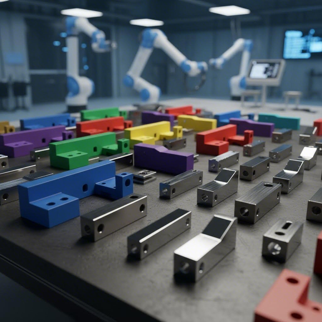
Compromisos entre prototipatge i producció
El prototipatge ràpid i les tirades de producció representen els extrems oposats d'un espectre cost-velocitat. Comprendre aquest compromís ajuda a pressupostar adequadament cada fase del projecte.
Prototipatge Ràpid entrega peces ràpidament, sovint en qüestió de dies, però amb un preu elevat per peça. Es paga per la flexibilitat, la rapidesa en la fabricació i la capacitat d'iterar dissenys sense grans compromisos. Això té sentit quan es validen conceptes, es comprova l'ajust i el funcionament, o es compleixen terminis urgents.
Sèries de producció sacrifica velocitat per obtenir economia. Els plazos més llargs permeten als fabricants agrupar eficientment la vostra feina, optimitzar el nesting de materials i programar operacions per assolir el màxim rendiment. Els costos per peça disminueixen substancialment, però es requereix un compromís amb quantitats més grans i plazos més llargs.
L'enfocament estratègic? Fer prototips en petites quantitats per validar dissenys, i després passar a quantitats de producció un cop les especificacions estiguin definides. Intentar obtenir preus de producció amb quantitats de prototip o esperar velocitats de prototip en sèries de producció condueix a frustració i excés pressupostari.
Optimització del disseny per a l'eficiència de costos
Decisions intel·ligents de disseny preses precoçment redueixen costos sense comprometre la funcionalitat. Tres estratègies ofereixen el major impacte:
Optimitzeu per a l'encabiratge: Els fabricants organitzen múltiples peces en una sola planxa per minimitzar desperdici. Dissenyar peces que s'ajustin eficientment—amb formes complementàries que encaixin com a peces d'un trencaclosques—redueix el consum de material. Les peces rectangulars amb orientacions consistents s'ajusten millor que les formes irregulars orgàniques.
Seleccioneu materials estratègicament: Segons experts en costos de fabricació , la selecció del material afecta directament la quantitat de residus, la velocitat de producció i la qualitat general. Pregunteu-vos si realment necessiteu la resistència addicional de l'alumini 6061 quan el 5052 compleix la funció a un cost inferior. Considereu si la resistència intrínseca a la corrosió de l'acer inoxidable elimina els costos d'acabat que s'aplicarien a l'acer al carboni.
Especifiqueu toleràncies adequades: Les toleràncies més estretes tenen un cost més elevat d'assolir i verificar. Especificar ±0,1 mm quan ±0,3 mm funciona perfectament bé afegirà despeses sense cap benefici funcional. Reserveu les especificacions de precisió per a característiques que realment les necessitin.
Aquests factors de cost interactuen amb tots els aspectes del vostre projecte, des de la selecció inicial del material fins a l'acabat final. Un cop aclarits els fonaments de la fixació de preus, explorar aplicacions específiques on el tall metàl·lic personalitzat aporta valor crític ajuda a contextualitzar aquestes inversions.
Aplicacions Automotrius i Industrials
On és on el tall personalitzat de fulls metàl·lics aporta el valor més crític? No cal mirar més enllà dels sectors automobilístic i industrial, on els components de precisió afecten directament la seguretat, el rendiment i la fiabilitat. Aquestes indústries exigeixen peces fabricades que compleixin especificacions rigoroses i que suportin condicions extremes, des dels compartiments del motor d’alta temperatura fins a les càrregues exigents de la suspensió.
Comprendre com la fabricació de fulls metàl·lics serveix aquestes aplicacions exigents ajuda a valorar per què la selecció de materials, la precisió del tall i les certificacions de qualitat són tan importants. Explorarem els components específics que depenen del tall metàl·lic de precisió i què diferencia una fabricació acceptable d’una excel·lent de categoria automobilística.
Components automobilístics que requereixen precisió
Els vehicles moderns contenen centenars de components metàl·lics fabricats a mida, cadascun dissenyat per a requisits específics de rendiment. A diferència de les aplicacions decoratives, on les petites variacions passen desapercebudes, les peces automotrius han d’encaixar amb precisió, suportar cicles repetits d’esforç i mantenir la seva integritat estructural durant anys de servei.
Les aplicacions més crítiques de la fabricació d’acer i del tall de precisió en l’automoció inclouen:
- Suports de muntatge del xassís: Aquestes peces fixen els sistemes de suspensió, els suports del motor i els panells de la carroceria al xassís del vehicle. Requereixen una elevada resistència a la tracció per suportar càrregues dinàmiques i una col·locació precisa dels forats per assegurar l’alineació del patró de cargols.
- Components de suspensió: Braços de comandament, suports d’amortidors i suports estabilitzadors suporten constantment esforços causats pels impactes de la carretera. Els sistemes de suspensió i direcció necessiten peces metàl·liques robustes i de gran precisió per garantir el comportament i la durabilitat durant tota la vida útil del vehicle.
- Escuts tèrmics: Aquests components tallats làser, situats prop dels sistemes d'escapament i del compartiment del motor, protegeixen els conductes sensibles d'electricitat i combustible de danys tèrmics. La selecció del material i l'ajust precís són essencials per a una gestió eficaç de la calor.
- Reforsos estructurals: Els suports reforçats de la bastida proporcionen resistència als impactes en zones de xoc. Aquests components requereixen propietats materials consistents i precisió dimensional per funcionar segons el disseny durant esdeveniments de col·lisió.
Més enllà dels components estructurals, la fabricació metàl·lica automotriu abasta inclosos els contenidors de bateries per a vehicles elèctrics (EV), suports personalitzats per a sistemes electrònics i peces de decoració estampades amb precisió. Cada aplicació comporta requisits específics pel que fa a la qualitat del material, l'acabat superficial i la tolerància dimensional.
Per què importen la resistència a la tracció i les propietats del material
Els components automotrius estan sotmesos a condicions de càrrega que posen de manifest qualsevol debilitat en la selecció del material o en la qualitat de la fabricació. Un suport de suspensió pot experimentar milers de cicles d'esforç diàriament: cada sot, gir i frenada transmet forces a través d'aquestes peces precises tallades.
Per això, els fabricants d'acer que presten serveis al sector automotriu presten especial atenció a les certificacions dels materials i a les seves propietats mecàniques. Les especificacions de resistència a la tracció asseguren que els components no s'estirin ni es deformin sota càrrega. La resistència al límit elàstic indica el nivell d'esforç a partir del qual comença la deformació permanent. La resistència a l'impacte determina el comportament en casos de càrregues sobtades.
Els metalls ferosos com l'acer al carboni i les qualitats d'alta resistència baixa en aliatge (HSLA) dominen les aplicacions estructurals per la seva relació favorable entre resistència i cost. Per a aplicacions lleugeres d'alt rendiment, les aliatges d'alumini ofereixen estalvis significatius de pes, encara que requereixin paràmetres de tall i tècniques d'unió diferents.
Aplicacions Industrials en Diversos Sectors
Més enllà del sector automotriu, la fabricació de xapes metàl·liques de precisió serveix per a aplicacions industrials on la fiabilitat i la durabilitat justifiquen la inversió en una fabricació de qualitat:
- Fabricació d'equipaments pesants: Les excavadores, maquinària agrícola i equips de manipulació de materials depenen de xapes d'acer tallades amb precisió per als seus bastidors estructurals i components resistent al desgast.
- Estructures aerospacials: Les cobertes d'aeronaus, suports i accessoris de muntatge exigeixen les toleràncies més ajustades i la traçabilitat completa del material.
- Sector energètic: Els envolvents elèctrics, carcasses de transformadors i sistemes de muntatge d'energies renovables requereixen materials resistents a la corrosió amb dimensions precises.
- Equipament mèdic: Les carcasses d'equips de diagnòstic i components de dispositius quirúrgics necessiten materials biocompatibles tallats segons especificacions molt exactes.
Els mètodes d'unió afegeixen una altra capa de complexitat en aplicacions industrials. Les tècniques de soldadura per punts uneixen eficientment components de xapa metàl·lica superposada per a producció d’alta volumetria. La soldadura d'alumini requereix equipament especialitzat i experiència professional a causa de les propietats tèrmiques del material i la formació de la capa d'òxid. Comprendre aquestes operacions posteriors influeix en les especificacions de tall i la selecció de materials des de l'inici del projecte.
La importància de la certificació IATF 16949
Quan s'adquireixen components per a aplicacions automotrius, hi ha una certificació que destaca sobre les altres: la IATF 16949. Aquesta norma específica de qualitat per al sector automobilístic va molt més enllà dels requisits bàsics de la ISO per abordar les necessitats úniques de les cadenes d'aprovisionament automotrius.
Per què és important aquesta certificació per als vostres projectes personalitzats de tall de metall? Segons especialistes del sector automobilístic , la IATF 16949 no és només una certificació de sistema de qualitat, sinó una revisió integral dels sistemes d’un proveïdor, incloent-hi la diversificació de la cadena d’aprovisionament, la gestió de riscos, els procediments de resposta i els processos d’millora contínua.
L'equip tècnic automotriu va desenvolupar aquesta norma específicament per abordar els riscos de pertorbacions en la cadena d’aprovisionament dins la fabricació automobilística complexa. Esdeveniments globals recents han demostrat com les interrupcions poden propagar-se a través de les línies d’aprovisionament, provocant aturades costoses de producció. Els proveïdors amb certificació IATF disposen de sistemes documentats per:
- Controlar i mitigar el risc de pertorbacions en l’aprovisionament
- Garantir una qualitat de producte constant mitjançant el control estadístic de processos
- Mantenir la traçabilitat dels materials des de les matèries primeres fins als components acabats
- Respondre de manera sistemàtica a problemes de qualitat o dificultats d’entrega
Per als fabricants d'equips originals (OEM) i subministradors de primer nivell, exigir la certificació IATF 16949 als socis en fabricació metàl·lica redueix la càrrega d'auditories alhora que assegura una qualitat constant. És cada cop més habitual que els fabricants automotrius exigeixin aquesta certificació precisament perquè el seu valor s'ha demostrat en mantenir les col·laboracions d'aprovisionament funcionant sense problemes.
Solucions Completes de Fabricació Automotriu
Les aplicacions automotrius més exigents requereixen més que simples capacitats de tall. Les solucions completes integren estampació metàl·lica personalitzada amb operacions de tall de precisió, doblegament i acabat per oferir components preparats per al muntatge.
Fabricants com Shaoyi (Ningbo) Metal Technology exemplifiquen aquest enfocament integrat, combinant sistemes de qualitat certificats segons l'IATF 16949 amb capacitats completes de fabricació. La seva capacitat de prototipatge ràpid en 5 dies permet als enginyers automotrius validar dissenys ràpidament abans de comprometre's amb eines de producció. Aquesta rapidesa en obtenir prototips és fonamental quan els terminis de desenvolupament són ajustats i les iteracions de disseny han de fer-se ràpidament.
Què cal buscar en un soci de fabricació especialitzat en l'automoció?
- Sistemes de qualitat certificats: La certificació IATF 16949 demostra el compromís amb la gestió de la qualitat de nivell automotriu
- Capacitats integrades: Embossat, tallat, doblegat i acabats sota un mateix sostre redueixen la complexitat de coordinació i els plazos d'entrega
- Prototipatge Ràpid: La capacitat de produir quantitats de prototips en dies en comptes de setmanes accelera els cicles de desenvolupament
- Suport en el disseny per a la fabricació (DFM): L'expertesa en disseny per a facilitar la fabricabilitat ajuda a optimitzar les peces per a una producció econòmica
- Experiència en Materials: Un coneixement profund dels materials de qualitat automotriu i dels seus requisits de fabricació
Sigui que estigueu desenvolupant components del xassís, suports de suspensió o refors estructurals, treballar amb un soci de fabricació que entengui els requisits automotrius des del principi evita redissenyos costosos i problemes de qualitat en fases posteriors. La inversió en certificacions i capacitats adequades dóna fruits al llarg de tot el cicle de vida del producte.
Un cop queden clares les aplicacions automotrius i industrials, la selecció del soci de fabricació adequat es converteix en la decisió final —i potser més important— del vostre procés de tall personalitzat.
Seleccionar el soci de tall personalitzat adequat
Heu definit els requisits del vostre projecte, seleccionat els materials i preparat els fitxers de disseny. Ara arriba la decisió que determinarà si el vostre projecte de tall personalitzat de metall té èxit o s'estanca: triar el soci de fabricació adequat. Cercar "fabricació de metall a prop meu" dóna dotzenes d'opcions, però com distingiu entre socis capacitats i aquells que no compliran amb els terminis, superaran els pressupostos o entregaran una qualitat deficient?
El repte s’intensifica perquè la majoria de tallers de fabricació ofereixen serveis similars en teoria. Les diferències reals apareixen en les capacitats, els sistemes de qualitat i les pràctiques de comunicació, que només es fan evidents durant la producció —sovint massa tard per poder corregir el rumb. Analitzem els criteris d’avaluació que distingeixen els socis fiables de les opcions arriscades.
Avaluació de les capacitats del proveïdor de serveis
Abans de sol·licitar pressupostos a tallers de fabricació propers a mi o de fer cerques com «fabricació de xapa metàl·lica propers a mi», establiu el vostre marc d’avaluació. Aquests criteris us ajuden a avaluar si un proveïdor pot realment oferir allò que exigeix el vostre projecte:
- Certificacions (ISO, IATF): La certificació ISO 9001:2015 demostra que una empresa ha implantat un sistema eficaç de gestió de la qualitat amb procediments documentats per al seguiment i la millora contínua. Per a aplicacions automotrius, la certificació IATF 16949 indica normes de qualitat específiques per al sector automobilístic, que aborden la fiabilitat de la cadena d’aprovisionament i la gestió de riscos.
- Capacitats de l'equipament: El fabricant disposa de la tecnologia de tall que requereix el vostre projecte? Les instal·lacions de servei complet, com les descrites per experts del sector, integren el tall per làser, el tall per plasma, el tall per jet d’aigua, la maquinària CNC i la conformació de precisió sota un mateix sostre. Aquesta integració permet un control més estricte de la producció i temps de resposta més curts.
- Opcions de material: Un partner competente manté en estoc o pot obtenir fàcilment els materials que requereix el seu projecte —siguin especificacions personalitzades de plaques metàl·liques, graus d'acer personalitzats o aliatges especials. Unes opcions limitades de materials poden obligar a fer concessions que afectin el rendiment final de la peça.
- Temps de resposta: Poden complir amb el seu calendari tant per a prototips com per a sèries de producció? Alguns projectes requereixen una resposta ràpida, mentre que en altres es prioritza l'eficiència de costos per sobre de la velocitat.
- Serveis de suport al disseny: L’empresa de fabricació ofereix consultoria d’enginyeria, suport CAD/CAM i proves de prototips? Aquesta capacitat és essencial per a projectes complexos que necessiten optimització del disseny.
Sorgeixen alertes quan els proveïdors no poden respondre clarament preguntes sobre cap d’aquests criteris. Respostes vagues sobre certificacions, reticència a parlar de detalls d’equipament o incapacitat per oferir estimacions de terminis indiquen mancances operatives que apareixeran durant el seu projecte.
El valor del suport DFM
Aquí hi ha alguna cosa que separa els bons socis de fabricació dels grans: el suport a la Disseny per a Fabricabilitat. Segons especialistes en desenvolupament de productes , si el disseny es realitza sense tenir en compte la fabricació des del principi, els costos poden augmentar significativament. Un disseny que no estigui optimitzat per a la fabricació pot requerir modificacions importants, incrementant els terminis i els costos.
Què ofereix realment el suport a la DFM?
- Assessorament en selecció de materials: Recomanar materials que equilibren els requisits de rendiment amb el cost i la facilitat de fabricació. Si productes similars poden utilitzar components compartits, es poden aprofitar les economies d'escala.
- Alineació del procés: Assegurar que el vostre disseny sigui adequat per al mètode de fabricació previst. Els components de xapa metàl·lica tenen límits definits pel que fa als radis de doblegat, i comprendre aquestes restriccions des del principi evita treballs innecessaris de revisió.
- Optimització de costos: Identificar modificacions de disseny que redueixin els costos de producció sense comprometre la funcionalitat. Això pot incloure l'ajust de toleràncies, la modificació de patrons de forats per millorar l'encabiment o la simplificació de la geometria.
- Planificació de prototip a producció: Assegurar que els dissenys provats en forma de prototip es tradueixin sense problemes en fabricació d’alta volumetria.
Col·laboradors com Shaoyi (Ningbo) Metal Technology demostra aquest enfocament integrat combinant un suport complet en DFM amb capacitats de prototipatge ràpid. El seu temps de resposta de 5 dies per al prototipatge permet als enginyers validar dissenys optimitzats per al DFM ràpidament abans de comprometre’s amb les eines de producció.
Preguntes a fer abans de fer una comanda
En avaluar tallers de transformació de metall propers a mi, aquestes preguntes revelen capacitats que sovint queden amagades en els materials comercials:
Sobre els sistemes de qualitat:
- Quines certificacions teniu i quan es van auditar per última vegada?
- Quin equip i processos d’inspecció verifiquen la precisió dimensional?
- Com gestioneu les peces no conformes detectades durant la producció?
- Podeu proporcionar informes d’inspecció d’article inicial?
Sobre les capacitats:
- Quines tecnologies de tall teniu internes i quines subministreu externament?
- Quines gruixos de material i mides de fulla podeu gestionar?
- Ofereixen operacions secundàries com doblegament, soldadura i acabats?
- Quins formats de fitxers CAD accepteu i preferiu?
Sobre la comunicació i la resposta:
- Quin és el temps habitual de resposta per a pressupostos?
- Com comuniquen les actualitzacions del projecte i els possibles problemes?
- Ofereixen suport d'enginyeria per a l'optimització del disseny?
- Què passa si les especificacions han de canviar durant la producció?
El temps de resposta en els pressupostos mereix una atenció especial com a indicador d'eficiència operativa. Un fabricant que respon amb pressupostos detallats en menys de 12 hores demostra processos optimitzats i una capacitat tècnica adequada. Els proveïdors que triguen dies o setmanes a pressupostar projectes senzills sovint tenen dificultats en la gestió de la capacitat, un repte que probablement també afectarà el vostre calendari de producció.
Experiència i coneixement del sector
L'experiència d'un fabricant es tradueix directament en els resultats del projecte. Tal com assenyalen experts del sector, els anys en el negoci sovint es tradueixen en un coneixement més profund dels materials, processos perfeccionats i la capacitat d'anticipar problemes abans que es converteixin en qüestions costoses.
Abans de triar un soci, pregunteu:
- Quants anys porten fabricant peces metàl·liques complexes?
- Tenen experiència al vostre sector o amb aplicacions similars?
- Poden compartir exemples, estudis de casos o referències?
L'experiència específica del sector és especialment important per a aplicacions regulades. La fabricació d'automoció, aerospacial i dispositius mèdics comporta requisits únics de certificació, expectatives de traçabilitat dels materials i necessitats de documentació de qualitat. Un fabricant experimentat en senyalització de construcció pot mancar de la infraestructura de sistemes de qualitat exigida pels proveïdors principals de l'automoció.
Escalabilitat i potencial de relació a llarg termini
El vostre soci ideal recolza tant les necessitats actuals com el creixement futur. Una empresa de fabricació ha de ser capaç d’escalar la producció des de prototips fins a sèries de producció complertes sense sacrificar la qualitat. Aquesta escalabilitat depèn de:
- Flexibilitat de capacitat: Poden augmentar o reduir la producció segons la vostra demanda?
- Redundància d'equipament: Si una màquina crítica falla, poden continuar la producció?
- Estabilitat de la cadena d'aprovisionament: Mantenen relacions amb diversos proveïdors de materials?
- Profunditat de la plantilla: Depenen només d’unes poques persones clau, o el coneixement està distribuït?
Una comunicació transparent és igualment essencial per a associacions a llarg termini. Un fabricant fiable ofereix terminis clars, actualitzacions proactives del projecte i expectatives realistes des del principi. Una bona comunicació evita sorpreses costoses i manté els projectes alineats des de la pressupostació fins a la lliurament.
Contractar un fabricant no és només una decisió de compra: és una inversió a llarg termini en el rendiment i la fiabilitat dels vostres productes.
Per a projectes centrats en l'automoció que requereixen qualitat certificada segons la IATF 16949, capacitats integrades de punxonat i tall, i una rapida entrega de prototips, Les solucions d'estampat automotiu de Shaoyi demostra l'enfocament integral que exigeixen els projectes complexos. El seu torn de resposta en 12 hores, prototipatge ràpid en 5 dies i suport complet en DFM exemplifiquen els nivells de resposta i capacitat que cal buscar en qualsevol proveïdor de fabricació.
El proveïdor de fabricació que trieu es converteix en una extensió de les vostres capacitats d'enginyeria i fabricació. Trieu basant-vos en competència demostrada, sistemes de qualitat certificats i pràctiques de comunicació que s'ajustin als requisits del vostre projecte, i construireu una relació que aportarà valor molt més enllà del primer comandament.
Preguntes freqüents sobre el tall personalitzat de xapes metàl·liques
1. Quant costa el tall personalitzat de xapa metàl·lica?
Els costos de tall personalitzat de fulla metàl·lica depenen del tipus de material, el gruix, la complexitat del disseny, la quantitat i els requisits d'acabat. Espereu entre 0,50 i 2 dòlars per polzada lineal per talls bàsics, mentre que les peces fabricades completes oscil·len entre 4 i 48 dòlars per peu quadrat. Els prototips individuals tenen un cost significativament més elevat per peça que les sèries de producció a causa de les tarifes fixes de configuració. Per exemple, un component d'acer galvanitzat podria costar 29 dòlars per una unitat però reduir-se a 3 dòlars cadascuna en encarregar deu unitats. L'elecció del material afecta dràsticament el preu: l'acer suau costa menys que l'alumini o l'acer inoxidable. Afegir recobriments en pols o altres acabats pot augmentar el cost de la peça entre un 50 i un 60%.
2. Quin mètode de tall és el millor per al meu projecte de fulla metàl·lica?
El mètode de tall òptim depèn del material, el gruix i els requisits de precisió. El tall làser ofereix una precisió extrema (±0,05 mm a ±0,1 mm) i vores neta per a xapes fines de menys de 25 mm, ideal per a dissenys intrincats i carcasses electròniques. El tall per jet d'aigua elimina completament la distorsió tèrmica i pot tallar materials fins a 200 mm de gruix, inclosos no metàl·lics, perfecte per a aplicacions aerospacials o sensibles a la calor. El tall per plasma ofereix la solució més ràpida i econòmica per a metalls conductors gruixuts superiors a 12 mm, habitualment utilitzat en la fabricació d'acer estructural. Moltes tallers professionals disposen de diverses tecnologies de tall, ja que cap mètode únic cobreix totes les aplicacions.
3. Em tallarà una botiga de ferrateria xapes metàl·liques?
La majoria de les botigues de material elèctric ofereixen serveis bàsics de tall de canonades, però no poden oferir talls personalitzats precisos de xapes metàl·liques. El tall personalitzat de xapes requereix equipament especialitzat com làsers de fibra, jets d’aigua o sistemes CNC de plasma que les botigues de ferreteria no disposen. Per a dimensions personalitzades, formes complexes o toleràncies ajustades, necessitarà un servei professional de fabricació metàl·lica. Les plataformes de fabricació en línia accepten fitxers DXF o STEP i lliuren peces tallades a mida en qüestió de dies. Taller de fabricació locals poden gestionar projectes complexos amb operacions secundàries com doblegament, soldadura i acabats que les botigues de ferreteria simplement no poden oferir.
4. Quins formats de fitxer es necessiten per al tall personalitzat de metall?
Els formats de fitxer vectorial són essencials per al tall precís de metalls; no es poden utilitzar fitxers matricials com JPEG o PNG. El DXF (Drawing Exchange Format) és l'estàndard del sector que la majoria de motors de pressupostació processen automàticament i que totes les màquines de tall accepten. Els fitxers DWG d'AutoCAD funcionen amb la majoria de fabricants, però potser necessiten conversió. Per a models 3D amb doblecs, envieu formats STEP (.step, .stp), SOLIDWORKS (.sldprt) o Autodesk Inventor (.ipt). Assegureu-vos que els fitxers estiguin a escala 1:1, amb contorns tancats, sense línies duplicades i amb el text convertit a contorns. Una preparació adequada dels fitxers redueix els cicles de revisió i evita retards costosos en la producció.
5. Com triar entre alumini i acer per al tall personalitzat?
Trieu l'alumini quan la reducció de pes sigui important: té aproximadament un terç del pes de l'acer i una resistència natural a la corrosió, cosa que el fa ideal per a l’aviació, els panells de carroceria d’automòbils i la senyalització exterior. Tanmateix, l'alumini és més car per lliura i té una resistència a la tracció més baixa. L'acer ofereix una resistència superior a un cost material més baix, ideal per a aplicacions estructurals, maquinària pesada i components portants. El compromís és un pes significativament més elevat i la susceptibilitat a la oxidació sense recobriments protectors. Per a entorns marins o humits, considereu l'ús d'acer galvanitzat o acer inoxidable 316. La selecció del material també afecta la tria del mètode de tall: metalls altament reflectants com l'alumini poden requerir longituds d'ona làser específiques.