 ছোট ছোট ব্যাচ, উচ্চ মান। আমাদের তাড়াতাড়ি প্রোটোটাইপিং সার্ভিস যাচাইকরণকে আরও তাড়াতাড়ি এবং সহজ করে —

মেটাল শীট লেজার কাটিং বিশ্লেষণ: ফাইবার বনাম সিও২ এবং কখন কোনটি শ্রেষ্ঠ
মেটাল শীট লেজার কাটিং আসলে কী বোঝায়
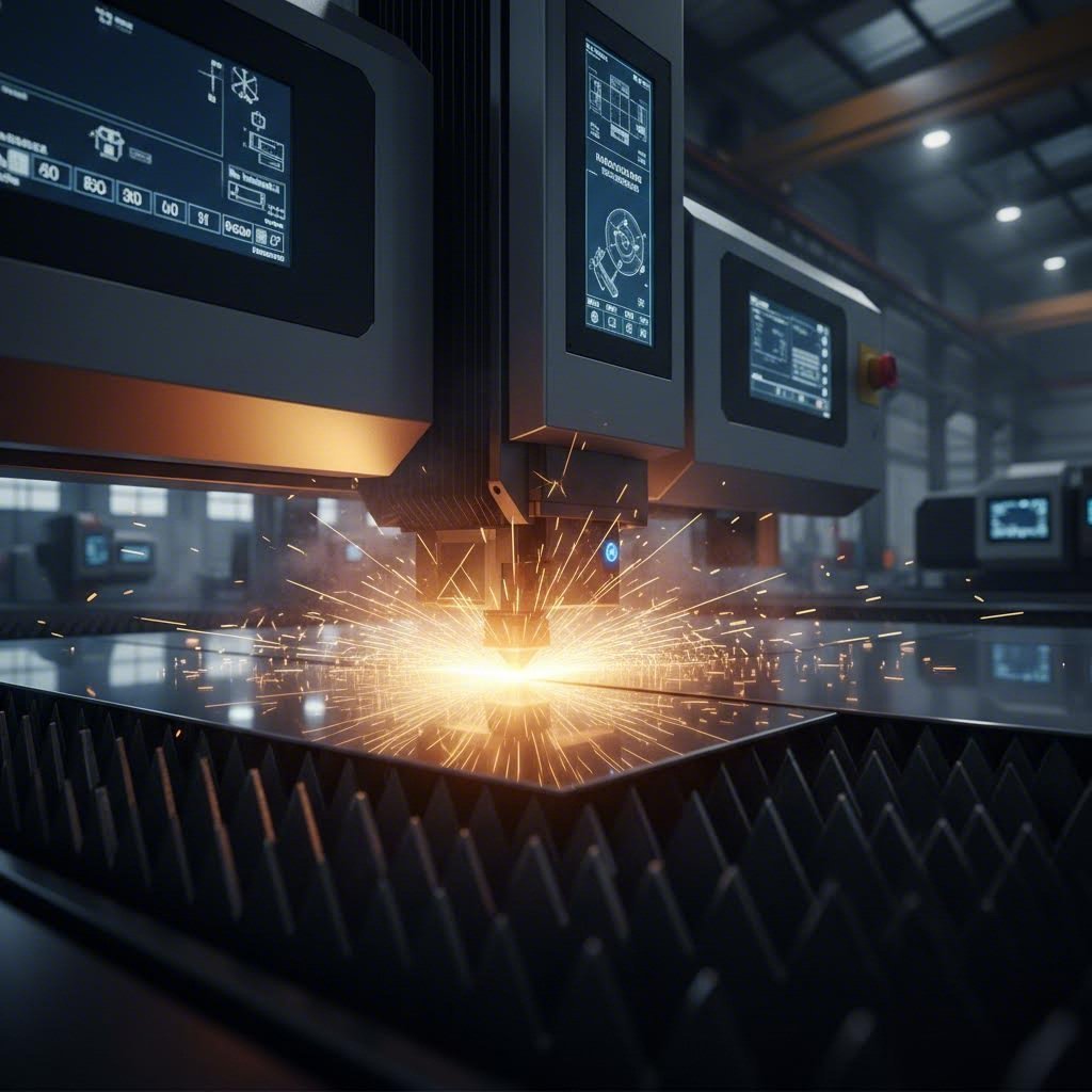
এমন আলোর রশ্মি কল্পনা করুন যা এতটাই ঘনীভূত যে এটি মাখনের মধ্যে গরম ছুরির মতো ইস্পাতকে কেটে ফেলতে পারে। মেটাল শীট লেজার কাটিংয়ের মূল সারমর্ম এটাই—একটি প্রিসিজন উৎপাদন প্রক্রিয়া যা স্মার্টফোনের উপাদান থেকে শুরু করে বিমানের অংশগুলি পর্যন্ত সবকিছু তৈরি করার পদ্ধতিকে মৌলিকভাবে পরিবর্তন করেছে।
এর মূলে রয়েছে একটি অত্যন্ত ঘনীভূত, সঙ্গতিপূর্ণ আলোক রশ্মি, যা বিশেষ অপটিক্সের মাধ্যমে প্রবাহিত হয়ে প্রোগ্রাম করা পথ ধরে উপাদানগুলিকে গলানো, পোড়ানো বা বাষ্পীভূত করার জন্য যথেষ্ট শক্তি প্রদান করে। ফলাফল? ধাতব পাতে পরিষ্কার ও নির্ভুল কাটিং, যা ঐতিহ্যবাহী যান্ত্রিক পদ্ধতিতে অসম্ভব হত।
ধাতব প্রস্তুতিতে নির্ভুলতার বিপ্লব
দ্য ধাতব প্রস্তুতিতে লেজার কাটিংয়ের যাত্রা 1960-এর দশকের শুরুতে শুরু হয়েছিল, যখন বেল ল্যাবস এয়ারোস্পেস উৎপাদনের চ্যালেঞ্জগুলি সমাধানের জন্য প্রাথমিক পরীক্ষা করেছিল। সেই সময়ে, টাইটানিয়াম এবং স্টেইনলেস স্টিলের মতো কঠিন উপাদানগুলি কাটা উৎপাদনের গুরুতর বাধা সৃষ্টি করেছিল। আজ, এই প্রযুক্তিটি শিল্প বিশেষজ্ঞদের দ্বারা উন্নত উৎপাদনের একটি মূল ভিত্তি হিসাবে স্বীকৃত একটি অবস্থায় উন্নীত হয়েছে।
কেন এই প্রক্রিয়াটি অপরিহার্য হয়ে উঠেছে? এই ক্ষমতাগুলি বিবেচনা করুন:
- এক মিলিমিটারের ভগ্নাংশে পরিমাপ করা নির্ভুলতা
- ঐতিহ্যবাহী কাটিং পদ্ধতির তুলনায় উল্লেখযোগ্যভাবে বেশি গতি
- কাস্টম টুলিং-এর প্রয়োজন ছাড়াই জটিল ডিজাইন তৈরির নমনীয়তা
- প্রথম কাট থেকে হাজারতম কাট পর্যন্ত ধ্রুবক মানের নিশ্চয়তা
লেজার প্রক্রিয়াকরণ উন্নত উৎপাদনের একটি অপরিহার্য অংশে পরিণত হয়েছে—মাইক্রোচিপ বিপ্লবের মতোই, লেজার প্রযুক্তি আরও কমপ্যাক্ট, শক্তি-দক্ষ এবং নির্ভরযোগ্য হয়ে উঠেছে, যা আমাদের উচ্চ-নির্ভুলতা ইঞ্জিনিয়ারিংয়ের দৃষ্টিভঙ্গি পালটে দিয়েছে।
আলোক রশ্মি থেকে পরিষ্কার কাট
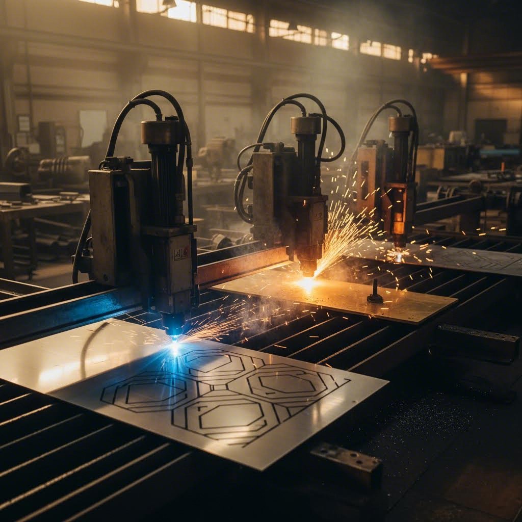
অবশ্যই, ঘনীভূত আলো কীভাবে কঠিন ধাতুর মধ্যে দিয়ে কাট করে? এই প্রক্রিয়াটি কাজের টেবিল জুড়ে একটি অপটিক্স হেড স্থানান্তরিত করে এবং নীচের ধাতব শীটের দিকে উচ্চ-তীব্রতা শক্তি প্রেরণ করে কাজ করে। যখন রশ্মি তার প্রোগ্রাম করা পথ ধরে এগিয়ে যায়, তখন এটি লক্ষ্য উপাদানকে বাষ্পীভূত বা গলিত করার জন্য যথেষ্ট ফোকাল পয়েন্ট তীব্রতা প্রদান করে। এটি সমগ্র শীট ক্ষমতাজুড়ে অভিন্ন নির্ভুলতা এবং কাটিংয়ের ফলাফল নিশ্চিত করে।
পাতলা ধাতুর প্রস্তুতিতে এটিকে যা বিশেষভাবে কার্যকর করে তোলে তা হল এর অ-যোগাযোগমূলক প্রকৃতি। যান্ত্রিক কাটিং সরঞ্জামগুলির বিপরীতে যা ক্ষয় হয়ে যায় এবং ধ্রুবক সমন্বয় প্রয়োজন, লেজার রশ্মি স্থির কর্মদক্ষতা বজায় রাখে। উপাদানের বিরুদ্ধে কোনও শারীরিক বল চাপানো হয় না, যার অর্থ এমনকি পাতলা বা ভঙ্গুর ধাতুর পাতও সমতল এবং বিকৃতি মুক্ত থাকে।
এই গাইডটি জুড়ে, আপনি বিভিন্ন অ্যাপ্লিকেশনের জন্য বিভিন্ন লেজার প্রকারগুলি কীভাবে তুলনা করে, আপনার প্রকৃতপক্ষে কতটা পাওয়ার লেভেল প্রয়োজন এবং কখন জলধারা বা প্লাজমা কাটিংয়ের মতো বিকল্পগুলির তুলনায় এই প্রযুক্তি আরও ভালো কর্মদক্ষতা দেখায় তা জানতে পারবেন। সরঞ্জামের বিনিয়োগ মূল্যায়ন করছেন আপনি বা আপনি যদি আরও ভাল ফলাফলের জন্য আপনার ডিজাইনগুলি অপ্টিমাইজ করতে চান, সেক্ষেত্রে সামনে থাকা অন্তর্দৃষ্টিগুলি আপনাকে আপনার ধাতু প্রস্তুতি প্রকল্পগুলিতে তথ্য-ভিত্তিক সিদ্ধান্ত নিতে সাহায্য করবে।
লেজার কাটিং প্রযুক্তি কীভাবে কাজ করে
আপনি লেজার কাটিং কী অর্জন করে তা দেখেছেন—কিন্তু সেই বিম যখন ধাতুতে আঘাত করে, আসলে কী ঘটে? এই প্রক্রিয়ার পিছনের বলবিদ্যা বোঝা আপনাকে একজন সাধারণ ব্যবহারকারী থেকে সমস্যা সমাধান, প্যারামিটারগুলি অপটিমাইজ করা এবং ক্রমাগত উন্নত ফলাফল অর্জনে সক্ষম করে তোলে।
একটি কমপ্যাক্ট ডেস্কটপ ইউনিট হোক বা শিল্প শক্তি, প্রতিটি লেজার কাটারই একই মৌলিক পদার্থবিদ্যা অনুসরণ করে। পার্থক্য হল প্রতিটি উপাদান কীভাবে প্রকৌশলী করা হয়েছে এবং অপারেটর সেই প্রকৌশলটি কীভাবে কাজে লাগায়।
বিমের পিছনের পদার্থবিদ্যা
একটি কাটার লেজার উদ্দীপিত নি:সরণ নামক একটি প্রক্রিয়ার মাধ্যমে আলো উৎপন্ন করে। এখানে সরল সংস্করণটি: বৈদ্যুতিক শক্তি CO₂ লেজারের জন্য গ্যাস মিশ্রণ এবং ফাইবার লেজারের জন্য ডোপযুক্ত অপটিক্যাল ফাইবারের মতো একটি গেইন মাধ্যমের মধ্যে পরমাণুগুলিকে উদ্দীপিত করে, যার ফলে সেগুলি ফোটন নি:সরণ করে। এই ফোটনগুলি আয়নার মধ্যে প্রতিফলিত হয়, প্রতিটি পাসের সাথে তীব্রতা বৃদ্ধি পায়, যতক্ষণ না তারা একটি সঙ্গতিপূর্ণ, একবর্ণী বিম গঠন করে।
এই বীমটিকে ইস্পাতের মধ্যে কাটা সক্ষম করে তোলয় কী? শক্তির ঘনত্ব। যখন সেই প্রবলিত আলোটি ফোকাসিং অপটিক্সের মধ্য দিয়ে যায়, তখন এটি সাধারণত 0.06 থেকে 0.15 মিমি চওড়া একটি ছোট জায়গায় সংকুচিত হয়। এই ক্ষুদ্র ফোকাল পয়েন্টটি যোগাযোগের স্থানে ধাতুকে তৎক্ষণাৎ গলিয়ে বা বাষ্পীভূত করার জন্য যথেষ্ট শক্তি কেন্দ্রিত করে।
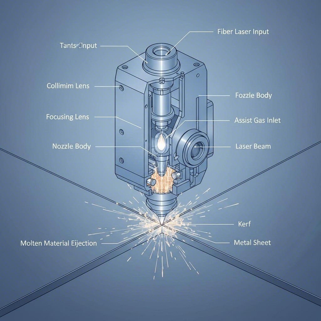
দ্য সম্পূর্ণ লেজার কাটিং ধাতু সিস্টেম পাঁচটি সংহত উপাদানের ওপর নির্ভর করে যা সুরে কাজ করে:
- লেজার সোর্স – সহসংবদ্ধ আলোক বীম উৎপন্ন করে (CO₂ টিউব, ফাইবার মডিউল বা ডায়োড অ্যারে)
- বিম ডেলিভারি – আয়না (CO₂) বা ফাইবার অপটিক কেবল (ফাইবার লেজার) এর মাধ্যমে আলো পরিবহন করে কাটিং হেডে
- কাটিং হেড – ফোকাসিং লেন্স, নোজেল এবং প্রায়শই উচ্চতা অনুভূতির প্রযুক্তি ধারণ করে
- মোশন সিস্টেম – নির্ভুল মোটর এবং রেল যা প্রোগ্রাম করা পথ বরাবর হেডটি নিয়ে যায়
- নিয়ন্ত্রণ সফটওয়্যার – ডিজাইন ফাইলগুলি ব্যাখ্যা করে এবং সমস্ত সিস্টেম উপাদানগুলি সমন্বয় করে
প্রতিটি উপাদানই আপনার চূড়ান্ত কাটার গুণমানকে প্রভাবিত করে। একটি দূষিত লেন্স বীমকে ছড়িয়ে দেয় এবং আপনার কার্ফকে বৃহত্তর করে তোলে। ক্ষয়প্রাপ্ত মোশন উপাদানগুলি কম্পন এবং ঢেউ খেলানো কিনারা তৈরি করে। এই শৃঙ্খলটি বোঝা আপনাকে সমস্যাগুলি দ্রুত নির্ণয় করতে সাহায্য করে।
আপনার কাটার গুণমানকে সাহায্যকারী গ্যাসগুলি কীভাবে প্রভাবিত করে
এখানে এমন কিছু রয়েছে যা অনেক শুরু করার লোকেরা উপেক্ষা করে: আপনার কাটার নোজেলের মধ্য দিয়ে প্রবাহিত গ্যাসটি লেজারের মতোই গুরুত্বপূর্ণ। সাহায্যকারী গ্যাসগুলি একসাথে তিনটি গুরুত্বপূর্ণ কাজ করে—তারা ধ্বংসাবশেষ থেকে লেন্সকে সুরক্ষা দেয়, গলিত উপাদানগুলি কাটার বাইরে ফেলে দেয় এবং কাটার সামনের প্রান্তে রাসায়নিক বিক্রিয়াকে প্রভাবিত করে।
গ্যাসের আপনার পছন্দটি মৌলিকভাবে পরিবর্তন করে কীভাবে ধাতব কাটার আপনার কাজের টুকরোর সাথে মিথস্ক্রিয়া করে:
অক্সিজেন (O₂) উত্তপ্ত ইস্পাতের সঙ্গে একটি তাপোৎপাদী বিক্রিয়া ঘটায়। ধাতব পদার্থটি আসলে জ্বলে, লেজারের চেয়ে বেশি তাপ শক্তি যোগ করে। কার্বন স্টিলের ক্ষেত্রে এটি কাটার গতি উল্লেখযোগ্যভাবে বাড়ায়, কিন্তু একটি জারিত প্রান্ত রেখে যায় যার পরবর্তী প্রক্রিয়াকরণের প্রয়োজন হতে পারে। মৃদু ইস্পাত কাটার সময়, নিষ্ক্রিয় গ্যাস পদ্ধতির তুলনায় অক্সিজেন-সহায়তায় কাটার গতি 30-40% পর্যন্ত বৃদ্ধি পায়।
নাইট্রোজেন (N₂) বিপরীত পদ্ধতি গ্রহণ করে। একটি নিষ্ক্রিয় গ্যাস হিসাবে, এটি কেবল গলিত উপাদানকে রাসায়নিক বিক্রিয়া ছাড়াই উড়িয়ে দেয়। ফলাফল? স্টেইনলেস স্টিল এবং অ্যালুমিনিয়ামে প্রায় আয়নার মতো পরিষ্কার, অক্সাইডমুক্ত প্রান্ত। আপসের বিষয়টি হল উচ্চতর গ্যাস খরচ এবং কিছুটা ধীর কাটার গতি।
গ্যাসের চাপও মানের উপর এমন প্রভাব ফেলে যা তাৎক্ষণিকভাবে বোঝা যায় না। সহায়ক গ্যাস গতিবিদ্যা সম্পর্কে গবেষণা এটি প্রকাশ করে যে অত্যধিক চাপ কোর্ফের মধ্যে বাউন্ডারি লেয়ার আলাদা হওয়ার কারণে কাটার গুণমান খারাপ করতে পারে। এমন হলে, গ্যাস প্রবাহ ল্যামিনারের পরিবর্তে টার্বুলেন্ট হয়ে যায়, যা গলিত উপাদান দক্ষতার সাথে সরানোর ক্ষমতা কমিয়ে দেয়। ফলস্বরূপ কাটা প্রান্তের নিচের অংশে বেশি রুক্ষতা হয় এবং বেশি ড্রস লেগে থাকে।
ড্রসকে সহজভাবে সংজ্ঞায়িত করলে: এটি সেই ধাতব উপাদান যা গলিত উপাদান সম্পূর্ণরূপে নির্গত না হলে আপনার কাটার নীচের প্রান্তে লেগে থাকে। সঠিক গ্যাস চাপ, গতি এবং ক্ষমতার সেটিংসের সংমিশ্রণ ড্রস গঠনকে কমিয়ে দেয়—আপনার পরিষ্কারের সময় বাঁচায় এবং পার্টের গুণমান উন্নত করে।
কার্ফ বোঝা এবং এটি কেন গুরুত্বপূর্ণ
কারফ হল কাটার সময় সরানো উপাদানের প্রস্থ—আসলে লেজার যখন উপাদানের মধ্য দিয়ে যায় তখন যে "ফাঁক" তৈরি হয়। নিখুঁত কাজের জন্য, কারফ বোঝা অপরিহার্য কারণ এটি সরাসরি আপনার চূড়ান্ত পার্টের মাত্রাকে প্রভাবিত করে।
উপাদানের পুরুত্ব, লেজারের ধরন এবং কাটিংয়ের পরামিতির উপর নির্ভর করে সাধারণত কারফের প্রস্থ 0.1 থেকে 0.3 মিমি পর্যন্ত হয়। ফাইবার লেজারগুলি সাধারণত CO₂ সিস্টেমের চেয়ে কম কারফ তৈরি করে কারণ এদের তরঙ্গদৈর্ঘ্য কম এবং ফোকাল স্পটগুলি আরও কাছাকাছি থাকে। জটিল নকশা বা এমন অংশগুলি কাটার সময় যেগুলি নিখুঁতভাবে একে অপরের সাথে মিলে যাওয়া প্রয়োজন, এই বিষয়টি বিশেষভাবে গুরুত্বপূর্ণ হয়ে ওঠে।
কারফ প্রস্থের পরিবর্তন কেন হয়? এখানে কয়েকটি কারণ জড়িত। বীম অপসারণ—আলোর দূরত্বের সাথে ছড়িয়ে পড়ার স্বাভাবিক প্রবণতা—এর অর্থ হল যে পুরু উপাদানগুলির ক্ষেত্রে উপরের চেয়ে নীচে কারফ প্রস্থ বেশি হয়। ফোকাসের অবস্থানও গুরুত্বপূর্ণ; উপাদানের পৃষ্ঠের কিছুটা নীচে ফোকাস বিন্দু রাখলে পুরু শীটগুলির কাটিংয়ের মান উন্নত হয়, যদিও এটি কারফ প্রস্থকে কিছুটা বাড়িয়ে দিতে পারে।
স্মার্ট ডিজাইনাররা কাটার পথগুলি সরিয়ে রেখে তাদের ফাইলগুলিতে কার্ফের বিষয়টি বিবেচনা করে। যদি আপনার লেজার 0.2 মিমি কার্ফ উৎপাদন করে এবং আপনার 10 মিমি বর্গাকার ছিদ্র প্রয়োজন হয়, তবে আপনি চারপাশে আপনার প্রয়োজনীয় মাত্রার 0.1 মিমি বাইরে কাটার পথ প্রোগ্রাম করবেন। আপনি যেই কার্ফ মান ইনপুট করবেন তা দেওয়ার পর অধিকাংশ পেশাদার কাটিং সফটওয়্যার স্বয়ংক্রিয়ভাবে এই ক্ষতিপূরণ পরিচালনা করে।
এই মৌলিক বিষয়গুলি স্থাপন করার পরে, পরবর্তী যুক্তিযুক্ত প্রশ্ন হয়ে ওঠে: আপনি আসলে কোন ধরনের লেজার বেছে নেবেন? উত্তরটি তীব্রভাবে নির্ভর করে আপনি কোন ধাতু কাটছেন এবং তার পুরুত্ব কত—এমন কারণগুলির উপর যা আমরা বিস্তারিত ভাবে বিশ্লেষণ করব।
ধাতু কাটার জন্য ফাইবার লেজার বনাম CO2 লেজার
এখন যেহেতু আপনি লেজার কাটার পেছনের যান্ত্রিক বিষয়গুলি বুঝতে পেরেছেন, সেরা প্রশ্নটি উঠে এসেছে: আপনার অপারেশনগুলির জন্য কোন ধরনের লেজার আপনি বেছে নেবেন? এই সিদ্ধান্তটি আপনার পরিচালন খরচ থেকে শুরু করে আপনি কোন উপকরণগুলি দক্ষতার সাথে প্রক্রিয়া করতে পারেন তা পর্যন্ত সবকিছুকে প্রভাবিত করে।
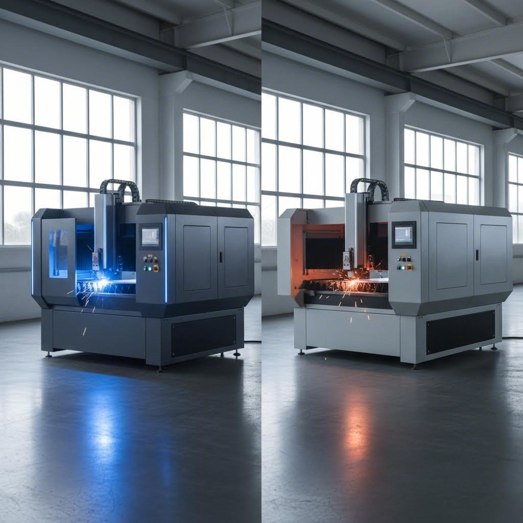
ফাইবার লেজার কাটিং মেশিন প্রযুক্তি পরিপক্ক হওয়ার সাথে সাথে ফাইবার এবং CO2 এর মধ্যে বিতর্ক আরও তীব্র হয়েছে। যেখানে CO2 সিস্টেমগুলি একসময় ধাতব উৎপাদন ক্ষেত্রে প্রভাব বিস্তার করত, সেখানে এখন ফাইবার লেজার কাটারগুলি বিশেষ করে পাতলা থেকে মাঝারি ধাতব অ্যাপ্লিকেশনের জন্য উল্লেখযোগ্য বাজার দখল করেছে। কিন্তু একটি সর্বজনীন বিজয়ী ঘোষণা করা মূল বিষয়টিকে একেবারে উপেক্ষা করে। প্রতিটি প্রযুক্তি নির্দিষ্ট পরিস্থিতিতে শ্রেষ্ঠ কাজ করে।
ফাইবার বনাম CO2 কর্মক্ষমতা বিশ্লেষণ
চলুন শুরু করা যাক এই সিস্টেমগুলিকে মৌলিকভাবে আলাদা করে তোলে এমন বিষয় দিয়ে। একটি ফাইবার লেজার কাটার সলিড-স্টেট প্রযুক্তি ব্যবহার করে, ইটারবিয়ামের মতো মৌলিক মৃত্তিকা দ্বারা দূষিত ফাইবার অপটিক কেবলের মাধ্যমে আলো উৎপন্ন করে। তরঙ্গদৈর্ঘ্য 1.064 মাইক্রোমিটারে অবস্থিত —CO2 লেজারের 10.6 মাইক্রোমিটার তরঙ্গদৈর্ঘ্যের চেয়ে প্রায় দশ গুণ ছোট।
তরঙ্গদৈর্ঘ্য কেন গুরুত্বপূর্ণ? ছোট তরঙ্গদৈর্ঘ্যগুলি ছোট ছোট স্থানে ফোকাস হয়, যা শক্তিকে আরও তীব্রভাবে কেন্দ্রীভূত করে। এর সরাসরি প্রভাব পড়ে পাতলা উপকরণগুলিতে কাটার গতি বাড়াতে। 1মিমি স্টেইনলেস স্টিলের পাত কাটার ক্ষেত্রে ফাইবার লেজার প্রতি মিনিটে 25 মিটার গতি অর্জন করতে পারে, যেখানে তুলনামূলক CO₂ সিস্টেমের ক্ষেত্রে তা মাত্র 8 মিটার প্রতি মিনিট।
দক্ষতার পার্থক্যও তুলনীয়ভাবে চমকপ্রদ। ফাইবার লেজারগুলি তড়িৎ শক্তিকে লেজার আলোতে প্রায় 35% দক্ষতায় রূপান্তরিত করে, অন্যদিকে CO₂ লেজারগুলি মাত্র 10-20% দক্ষতা অর্জন করে। ব্যবহারিক দিক থেকে বিবেচনা করলে, 2 কিলোওয়াটের ফাইবার লেজার কাটিং মেশিন ধাতুতে তুলনীয় কাটিং ক্ষমতা প্রদর্শনের ক্ষেত্রে CO₂ ইউনিটের তুলনায় মোট বিদ্যুৎ খরচের প্রায় এক-তৃতীয়াংশ ব্যবহার করে।
CO2 প্রযুক্তি বিভিন্ন শক্তি নিয়ে আসে। দীর্ঘতর তরঙ্গদৈর্ঘ্য কাঠ, এক্রিলিক এবং টেক্সটাইলের মতো জৈব উপকরণের মধ্যে আরও কার্যকরভাবে শোষিত হয়। বিভিন্ন ধরনের উপকরণ প্রক্রিয়াকরণকারী দোকানগুলির জন্য এই বহুমুখীতা গুরুত্বপূর্ণ। CO2 সিস্টেমগুলি বিশেষ করে অ-ধাতব ঘন উপকরণগুলি উৎকৃষ্ট কিনারা গুণমান নিয়ে পরিচালনা করে। 20 মিমি পুরুত্বের বেশি উপকরণ কাটার ক্ষেত্রে, CO2 লেজারগুলি প্রায়শই আরও মসৃণ ফিনিশ প্রদান করে।
এখানে এমন একটি বিষয় রয়েছে যা অনেক ক্রেতাকে অসতর্ক করে তোলে: প্রতিফলনের মাত্রা। অ্যালুমিনিয়াম, তামা এবং পিতলের মতো ধাতুগুলি সক্রিয়ভাবে অবলোহিত আলো প্রতিফলিত করে। প্রতিফলিত শক্তি অপটিক্যাল উপাদানগুলিকে ক্ষতি করতে পারে বলে ঐতিহ্যবাহী CO2 লেজারগুলি এই উপকরণগুলির সাথে সংগ্রাম করে। ফাইবার লেজার কাটারগুলি প্রতিফলিত ধাতুগুলি অনেক বেশি নিরাপদে পরিচালনা করে—তাদের ডেলিভারি সিস্টেম স্বতঃস্ফূর্তভাবে পিছনের প্রতিফলনের ক্ষতি প্রতিরোধ করে, অ্যালুমিনিয়াম লেজার কাটাকে উল্লেখযোগ্যভাবে আরও ব্যবহারিক করে তোলে।
আপনার ধাতব অ্যাপ্লিকেশনের সাথে লেজার ধরন মেলানো
ফাইবার এবং CO2-এর মধ্যে পছন্দ করা কোন প্রযুক্তি "ভালো" তা নির্বিশেষে আপনার নির্দিষ্ট উৎপাদনের চাহিদা অনুযায়ী কোনটি খাপ খায় তা নির্ধারণ করার বিষয়। এই অ্যাপ্লিকেশন-নির্দিষ্ট দৃষ্টিভঙ্গি বিবেচনা করুন:
ইস্পাত (কার্বন এবং মৃদু ইস্পাত) কাটা হল সবচেয়ে সাধারণ অ্যাপ্লিকেশন। উভয় ধরনের লেজার এই উপাদান দক্ষতার সাথে প্রক্রিয়া করে, কিন্তু 6 মিমি-এর নিচে শীটের জন্য ফাইবার লেজার প্রাধান্য পায়। উচ্চ পরিমাণে উৎপাদনে এর গতির সুবিধা আরও বৃদ্ধি পায়—তিনগুণ দ্রুত কাটা মানে আপনার আউটপুট ক্ষমতা তিনগুণ বৃদ্ধি করা যেখানে কোন অতিরিক্ত সরঞ্জাম যোগ করা হয় না। 12 মিমি-এর বেশি ঘন কার্বন স্টিল প্লেটের ক্ষেত্রে, CO2 লেজার গতির ব্যবধান কমিয়ে দেয় এবং ক্লিন এজ দিতে পারে।
স্টেইনলেস স্টিল শীট প্রক্রিয়াকরণ প্রায় সর্বত্র ফাইবার প্রযুক্তিকে প্রাধান্য দেয়। উপাদানের ক্রোমিয়াম সামগ্রী ফাইবার লেজার তরঙ্গদৈর্ঘ্যের প্রতি অসাধারণভাবে সাড়া দেয়। যখন নাইট্রোজেন সহায়ক গ্যাস ব্যবহার করা হয়, ফাইবার লেজার কাটার উজ্জ্বল, অক্সাইডমুক্ত এজ তৈরি করে যার কোনো দ্বিতীয় পর্যায়ের ফিনিশিংয়ের প্রয়োজন হয় না। প্রাথমিকভাবে স্টেইনলেস স্টিল শীট মেটাল কাটার উৎপাদন সুবিধাগুলি ফাইবার বিনিয়োগ থেকে সবচেয়ে বেশি ROI পায়।
যখন আপনার অ্যালুমিনিয়াম কাটার জন্য লেজারের প্রয়োজন হয় , ফাইবার প্রায় অপরিহার্য হয়ে ওঠে। অতীতে অ্যালুমিনিয়ামের উচ্চ প্রতিফলনক্ষমতা CO2 সিস্টেমের জন্য গুরুতর সমস্যা সৃষ্টি করেছিল—প্রতিফলিত শক্তি আলোক পথে ফিরে গিয়ে দামি উপাদানগুলি ক্ষতিগ্রস্ত করতে পারত। আধুনিক ফাইবার লেজারগুলি এই সমস্যা সম্পূর্ণরূপে এড়িয়ে যায়। তাদের সলিড-স্টেট ডেলিভারি সিস্টেম ঝুঁকি ছাড়াই প্রতিফলনশীল উপকরণ পরিচালনা করতে পারে, যার ফলে অ্যালুমিনিয়াম শীট প্রক্রিয়াকরণ বিপজ্জনক না হয়ে নিয়মিত কাজে পরিণত হয়।
তামা ও পিতল এমন প্রতিফলনের চ্যালেঞ্জ উপস্থাপন করে যা ফাইবার লেজার নিরাপদে পরিচালনা করে। এই উপকরণগুলি তাপও দ্রুত পরিচালনা করে, যা ধীর কাটিং পদ্ধতির সাথে কাটার মান কমিয়ে দিতে পারে। এখানে ফাইবারের গতির সুবিধাটি বিশেষভাবে মূল্যবান প্রমাণিত হয়—দ্রুত কাটা মানে আশেপাশের উপকরণে তাপ ছড়ানোর জন্য কম সময়।
ডায়োড লেজার সম্পর্কে কী? এই কমপ্যাক্ট, কম-শক্তির সিস্টেমগুলি হবিস্ট এবং হালকা বাণিজ্যিক অ্যাপ্লিকেশনগুলিতে জনপ্রিয়তা অর্জন করেছে। যদিও এগুলি ধাতুগুলিতে মার্কিং এবং খোদাই করতে পারে, তাদের শক্তি আউটপুট (সাধারণত 100 ওয়াটের নিচে) পাতলা উপকরণ এবং ধীর কাটিং গতির জন্য সীমিত থাকে। গুরুতর ধাতু নির্মাণের জন্য, ডায়োড লেজারগুলি কাটার চেয়ে মার্কিং সরঞ্জাম হিসাবে ভালো কাজ করে।
| তুলনা উপাদান | ফাইবার লেজার | Co2 লেজার |
|---|---|---|
| সেরা ধাতব অ্যাপ্লিকেশন | স্টেইনলেস স্টিল, অ্যালুমিনিয়াম, তামা, পিতল, পাতলা কার্বন স্টিল | মোটা কার্বন স্টিল, অধাতু ক্ষমতা প্রয়োজন এমন মিশ্র উপকরণের দোকান |
| সাধারণ পাওয়ার রেঞ্জ | শিল্প ইউনিটের জন্য 1kW - 30kW+ | ধাতু কাটার জন্য সাধারণত 1kW - 6kW |
| চলাচলের খরচ | নিম্ন (35% বৈদ্যুতিক দক্ষতা, ন্যূনতম খরচযোগ্য উপাদান) | উচ্চতর (10-20% দক্ষতা, নিয়মিত গ্যাস টিউব প্রতিস্থাপন) |
| রক্ষণাবেক্ষণের প্রয়োজনীয়তা | ন্যূনতম—কোনও আয়না সাজানোর প্রয়োজন নেই, সীলযুক্ত ফাইবার ডেলিভারি | নিয়মিত আয়না সাজানো, প্রতি 20,000-30,000 ঘন্টার পর গ্যাস টিউব প্রতিস্থাপন |
| কাটার গতি (পাতলা ধাতু) | 6 মিমির নিচের উপকরণগুলিতে 3 গুণ দ্রুত | ভিত্তি তুলনা বিন্দু |
| প্রতিফলিত উপকরণ পরিচালনা | চমৎকার—অ্যালুমিনিয়াম, তামা, পিতলের জন্য নিরাপদ | সমস্যাযুক্ত—পিছনের দিকে প্রতিফলনের ক্ষতির ঝুঁকি |
| জীবনকাল | ১,০০,০০০ ঘন্টা পর্যন্ত | সাধারণত 20,000-30,000 ঘন্টা |
| প্রাথমিক বিনিয়োগ | উচ্চতর আদ্যকালিক খরচ | প্রাথমিক ক্রয়মূল্য কম |
| অ-ধাতব ক্ষমতা | সীমিত—মূলত ধাতব-কেন্দ্রিক | কাঠ, অ্যাক্রিলিক, বস্ত্র এবং প্লাস্টিকের জন্য উত্কৃষ্ট |
মালিকানা ব্যয়ের মোট হিসাবটি প্রায়শই প্রথমবারের ক্রেতাদের অবাক করে দেয়। প্রাথমিক ক্রয়মূল্য বেশি হওয়া সত্ত্বেও, ফাইবার লেজার কাটিং মেশিনগুলি তাদের কার্যকরী আয়ু জুড়ে প্রায়শই প্রতি অংশে কম খরচ দেয়। 100,000 ঘন্টার আয়ু—CO2 টিউবের চেয়ে প্রায় পাঁচ গুণ বেশি—এর সাথে বিদ্যুৎ খরচ হ্রাস এবং প্রায় শূন্য খরচযোগ্য উপকরণের খরচ উচ্চ-আয়তনের ধাতু নির্মাণের জন্য দীর্ঘমেয়াদী অর্থনীতিকে আকর্ষক করে তোলে।
তবে, আপনার উৎপাদন মিশ্রণে ধাতু কাটার পাশাপাশি উল্লেখযোগ্য অ-ধাতব কাজ রয়েছে, তবে CO2 সিস্টেমের উপাদানের বহুমুখিতা এর উচ্চতর পরিচালন খরচকে ন্যায্যতা দিতে পারে। কিছু সুবিধাতে উভয় প্রযুক্তি বজায় রাখা হয়, যে নির্দিষ্ট আবেদনটি সবচেয়ে দক্ষতার সাথে পরিচালনা করে সেই লেজার ধরনের দিকে চালানো হয়।
আপনার উপকরণগুলির জন্য কোন লেজার ধরন উপযুক্ত তা বোঝা হল সমীকরণের মাত্র অর্ধেক। পরবর্তী গুরুত্বপূর্ণ চলক—লেজার পাওয়ার—নির্ধারণ করে যে আপনি কতটা পুরুত্ব কাটতে পারবেন এবং কী গতিতে কাটতে পারবেন। আপনার সাধারণ কাজের ভারের সাথে কিলোওয়াট মিলিয়ে নেওয়া হলে ক্ষমতার অভাবে হওয়া হতাশা এবং অপ্রয়োজনীয় মূলধন ব্যয় দুটোই এড়ানো যায়।
আপনার প্রয়োগের জন্য সঠিক লেজার পাওয়ার নির্বাচন
আপনি আপনার লেজার ধরন নির্বাচন করেছেন—কিন্তু আপনার আসলে কত কিলোওয়াট প্রয়োজন? এই প্রশ্নটি অন্য যে কোনো কিছুর চেয়ে বেশি ক্রেতাকে ভুল পথে নিয়ে যায়, ফলস্বরূপ হয় উৎপাদনে বাধা হয় এমন ক্ষমতাহীন মেশিন কেনা হয়, নয়তো এমন ক্ষমতা কেনা হয় যা কখনো ব্যবহার করা হবে না এবং মূলধন নিষ্ক্রিয় হয়ে থাকে।
কেবল বেশি পুরু উপকরণ কাটার জন্যই নয়, পাওয়ার নির্বাচন করা হয় না। কিলোওয়াট, উপকরণের বৈশিষ্ট্য এবং কাটার গতির মধ্যে সম্পর্ক এমন একটি সিদ্ধান্ত ম্যাট্রিক্স তৈরি করে যা সরাসরি আপনার কার্যকরী দক্ষতা এবং প্রতি অংশের খরচের অর্থনীতির উপর প্রভাব ফেলে। চলুন আপনার নির্দিষ্ট প্রয়োগের জন্য স্পেসিফিকেশনগুলি আসলে কী অর্থ বহন করে তা বোঝার চেষ্টা করি।
ধাতুর ধরন এবং পুরুত্ব অনুযায়ী শক্তির প্রয়োজনীয়তা
এখানে মূল নীতিটি হল: লেজার পাওয়ার আপনার সর্বোচ্চ কাটিং পুরুত্ব নির্ধারণ করে এবং আরও গুরুত্বপূর্ণভাবে, বিভিন্ন পুরুত্ব কাটার গতি। 2kW-এ রেট করা একটি ধাতব লেজার কাটিং মেশিন প্রায় 12mm মৃদু ইস্পাত কাটতে পারে—কিন্তু অত্যন্ত ধীর গতিতে। 6kW-এ উন্নীত করুন, এবং একই কাটা তিন থেকে চার গুণ দ্রুত ঘটে।
অনুযায়ী শিল্প পুরুত্ব চার্ট , সাধারণ উপকরণগুলির মধ্যে শক্তি এবং ক্ষমতার মধ্যে সম্পর্কটি ভবিষ্যদ্বাণীযোগ্য প্যাটার্ন অনুসরণ করে:
| উপাদান | 1.5-2kW পরিসর | 3-4kW পরিসর | 6kW+ পরিসর |
|---|---|---|---|
| মিল্ড স্টিল | 8mm পর্যন্ত (মাঝারি গতি) | 16mm পর্যন্ত | ২৫মিমি পর্যন্ত |
| স্টেইনলেস স্টিল | 6mm পর্যন্ত | ১২মিমি পর্যন্ত | ২০মিমি পর্যন্ত |
| অ্যালুমিনিয়াম শীট | ৪ মিমি পর্যন্ত | ৮ মিমি পর্যন্ত | ১২মিমি পর্যন্ত |
| পিতল | ৩ মিমি পর্যন্ত | 6mm পর্যন্ত | ৮ মিমি পর্যন্ত |
| তামা | ২ মিমি পর্যন্ত | ৪ মিমি পর্যন্ত | 6mm পর্যন্ত |
লক্ষ্য করুন যে সমতুল্য শক্তির স্তরে অ্যালুমিনিয়াম শীট, পিতল এবং তামা ইস্পাত প্লেটের তুলনায় উল্লেখযোগ্যভাবে কম পুরুত্বের ক্ষমতা দেখায়? এটি কোনও মেশিনের সীমাবদ্ধতা নয়—এটি পদার্থবিজ্ঞানের কাজ।
যখন 316 স্টেইনলেস স্টিল বা অনুরূপ ক্ষয়রোধী খাদগুলি প্রক্রিয়া করা হয়, তখন আপনি লক্ষ্য করবেন যে একই পুরুত্বের মৃদু ইস্পাতের তুলনায় এগুলির প্রায় 15-20% বেশি শক্তির প্রয়োজন হয়। ক্রোমিয়াম এবং নিকেলের উপস্থিতি লেজার শক্তি শোষণ এবং পরিচালনার ক্ষেত্রে উপাদানের প্রভাব ফেলে, যা আপনার কাটিং প্যারামিটারগুলিতে সামঞ্জস্য আনতে বাধ্য করে।
যেখানে আরও কিলোওয়াট আসলে গুরুত্বপূর্ণ
এখানেই ক্ষমতার নির্বাচন জটিল হয়ে ওঠে। আরও কিলোওয়াট সর্বদা ভালো ফলাফল বয়ে আনে না—এটি সেই উপকরণগুলির জন্য দ্রুত ফলাফল বয়ে আনে যা অতিরিক্ত শক্তি ব্যবহার করতে পারে। এই পার্থক্যটি বোঝা ব্যয়বহুল অতিরিক্ত স্পেসিফিকেশন এড়াতে সাহায্য করে।
গতি গুণনের প্রভাব: ধাতুর জন্য 4kW রেটযুক্ত একটি লেজার কাটিং মেশিন 2kW ইউনিটের চেয়ে দ্বিগুণ দ্রুত কাটে না। এই সম্পর্কটি রৈখিক নয়। পাতলা উপকরণের ক্ষেত্রে আপনি 2.5 গুণ গতি বৃদ্ধি দেখতে পারেন কিন্তু সর্বোচ্চ পুরুত্ব ক্ষমতার কাছাকাছি শুধুমাত্র 1.3 গুণ উন্নতি দেখা যায়। উৎপাদন দক্ষতার জন্য সর্বোত্তম বিন্দুটি সাধারণত মেশিনের সর্বোচ্চ পুরুত্ব রেটিংয়ের 40-60% এর কাছাকাছি হয়।
প্রতিফলিত উপকরণ বিবেচনা: অ্যালুমিনিয়াম এবং তামা এমন চ্যালেঞ্জ তৈরি করে যা শুধুমাত্র উচ্চ ক্ষমতা দিয়ে সমাধান করা সম্ভব নয়। এই ধাতুগুলি অবরক্ত লেজার শক্তি সক্রিয়ভাবে প্রতিফলিত করে— প্রতিফলিত উপকরণ কাটার উপর গবেষণা এটি নিশ্চিত করে যে 2-6kW পরিসরের ফাইবার লেজারগুলি এই অ্যাপ্লিকেশনগুলি সবচেয়ে কার্যকরভাবে পরিচালনা করে কারণ তাদের ছোট তরঙ্গদৈর্ঘ্য ভালো শোষণের হার অর্জন করে।
প্রতিফলনশীল ধাতুগুলি কেন এত চাহিদাপূর্ণ? উপাদানটিতে শক্তি শোষণ না করে তাদের মুক্ত ইলেকট্রনগুলি লেজার শক্তিকে উৎসের দিকে ফিরিয়ে দেয়। এর অর্থ হল যে একই মেশিন যদি ইস্পাত কাটে তবে তার চেয়ে তামা কাটার জন্য লেজার ধাতব কাটার মেশিনটির প্রতি মিলিমিটার বেধের জন্য আরও বেশি শক্তির প্রয়োজন হয়—যদিও তামা প্রকৃতপক্ষে নরম। কারণ শক্তিটি কার্যকরভাবে শোষিত হচ্ছে না।
তাপীয় পরিবাহিতা সমস্যাটিকে আরও বাড়িয়ে তোলে। অ্যালুমিনিয়াম এবং তামা চারপাশের উপাদানের মাধ্যমে তাপ দ্রুত ছড়িয়ে দেয়। যখন আপনি কাটার সামনে শক্তি কেন্দ্রীভূত করার চেষ্টা করছেন, ঠিক তখন ধাতুটি সক্রিয়ভাবে সেই তাপ সরিয়ে নিচ্ছে। এই প্রভাব অতিক্রম করতে উচ্চতর শক্তি সাহায্য করে, কিন্তু কাটার গতি সমানভাবে গুরুত্বপূর্ণ হয়ে ওঠে—দ্রুত কাটা তাপ ছড়ানোর জন্য কম সময় দেয়, যার ফলে ছোট তাপ-প্রভাবিত অঞ্চল সহ পরিষ্কার প্রান্ত তৈরি হয়।
ব্যবহারিক সিদ্ধান্ত গ্রহণের জন্য, এই নির্দেশাবলী বিবেচনা করুন:
- 1.5-2kW সিস্টেম যেসব জব শপগুলি প্রাথমিকভাবে পাতলা উপকরণ (৬ মিমির নিচে) প্রক্রিয়াজাত করে বা কম উৎপাদন পরিমাণের সুবিধাগুলির জন্য উপযুক্ত, যেখানে কাটার গতি প্রাথমিক বিনিয়োগের তুলনায় কম গুরুত্বপূর্ণ
- ৩-৪ কিলোওয়াট সিস্টেম সাধারণ নির্মাণ কাজের সবচেয়ে বিস্তৃত পরিসর পরিচালনা করে, মাঝারি আকারের উৎপাদনের জন্য ক্ষমতা এবং পরিচালন খরচের মধ্যে ভারসাম্য বজায় রেখে
- ৬ কিলোওয়াট বা তার বেশি সিস্টেম ১২ মিমির বেশি ইস্পাতের পাত নিয়মিত কাটার ক্ষেত্রে, মাঝারি পুরুত্বের উপকরণের উচ্চ পরিমাণ প্রক্রিয়াজাত করার ক্ষেত্রে, অথবা যেখানে উৎপাদন গতি সরাসরি আয়কে প্রভাবিত করে, সেসব ক্ষেত্রে তাদের প্রিমিয়াম মূল্য ন্যায্যতা পায়
সবচেয়ে সাধারণ ভুল? মাঝে মাঝে ঘন কাটার জন্য সর্বোচ্চ ক্ষমতা কেনা। আপনার কাজের ৮০% যদি ৩ মিমি স্টেইনলেস স্টিল এবং মাঝে মাঝে ১৫ মিমি ইস্পাতের পাতের সাথে জড়িত হয়, তবে একটি ৪ কিলোওয়াট মেশিন আপনার দৈনিক উৎপাদনকে দক্ষতার সাথে পরিচালনা করবে, এমনকি ভারী কাজগুলিও করবে—শুধু কম গতিতে। হাজার হাজার ঘন্টা অপারেটিংয়ের মধ্যে ৬ কিলোওয়াট সিস্টেমের তুলনায় শক্তি খরচের সাশ্রয় উল্লেখযোগ্যভাবে বৃদ্ধি পায়।
বিদ্যুৎ চাহিদা পরিষ্কার হওয়ার পর, পরবর্তী প্রশ্ন হয়ে ওঠে: আপনি আসলে আপনার কাটিং থেকে কতটা নির্ভুলতা আশা করতে পারেন? সহনশীলতা, কিনারার গুণমান এবং তাপ-প্রভাবিত অঞ্চলগুলি আপনি আপনার কাটিং প্যারামিটারগুলি কীভাবে কনফিগার করেন তার উপর নির্ভর করে ব্যাপকভাবে পরিবর্তিত হয়—এমন ফ্যাক্টরগুলি যা নির্ধারণ করে যে আপনার পার্টগুলি মাধ্যমিক প্রক্রিয়াকরণ ছাড়াই নির্দিষ্টকরণ পূরণ করে কিনা।
নির্ভুলতার মান এবং কাটিংয়ের গুণমানের প্রত্যাশা
তাহলে আপনি আপনার পাওয়ার সেটিংস ঠিক করে নিয়েছেন এবং সঠিক লেজার ধরন নির্বাচন করেছেন—কিন্তু আপনার পার্টগুলি আসলে নির্দিষ্টকরণ পূরণ করবে কি? এই প্রশ্নটি ব্যয়বহুল পরীক্ষার থেকে পেশাদার ধাতু লেজার কাটিংকে আলাদা করে। সহনশীলতার ক্ষমতা এবং কিনারার গুণমানের উপাদানগুলি বোঝার মাধ্যমে নিশ্চিত করা হয় যে আপনার সমাপ্ত পার্টগুলি খরচ বাড়ানো পুনরায় কাজ ছাড়াই যেমনটা ডিজাইন করা হয়েছে তেমনভাবে কাজ করে।
এখানে যা ঘটে তা হল: অনেক ফ্যাব্রিকেটরদের কঠোর অভিজ্ঞতা হয় যে, একটি লেজার যা একটি নির্দিষ্ট গতিতে ধাতুকে সুন্দরভাবে কাটে, তা দ্রুত চালালে অসম এবং ড্রস-পূর্ণ কিনারা তৈরি করে। কাটিং প্যারামিটার এবং নির্ভুলতার মধ্যে সম্পর্কটি স্বতঃস্ফূর্ত নয়, কিন্তু এটি দক্ষতার সাথে আয়ত্ত করা আপনার আউটপুটের গুণমানকে রূপান্তরিত করে।
সহনশীলতার নির্দিষ্টকরণ বোঝা
ধাতব পাতের লেজার কাটিং মূল্যায়নের সময়, চারটি নির্ভুলতা বিশদ নির্ধারণ করে যে অংশগুলি আপনার প্রয়োজনীয়তা পূরণ করে কিনা:
অবস্থানগত নির্ভুলতা প্রোগ্রাম করা স্থানাঙ্কের সাপেক্ষে লেজার কাটার ধাতব ব্যবস্থা কতটা নিখুঁতভাবে কাটা স্থাপন করে তা পরিমাপ করে। শিল্প নির্ভুলতার মান অধিকাংশ উৎপাদন সরঞ্জাম 0.5 মিমি ত্রুটির পরিসরের মধ্যে প্রক্রিয়াকরণের নির্ভুলতা অর্জন করে, আর উচ্চ-নির্ভুলতার ব্যবস্থাগুলি 0.3 মিমি সহনশীলতায় পৌঁছায়। এর তুলনামূলক ধারণা হিসাবে, এটি তিনটি কাগজের পাতের পুরুত্বের সমান—যা বেশিরভাগ কাঠামোগত উপাদানের জন্য যথেষ্ট, কিন্তু নির্ভুল অ্যাসেম্বলিগুলির জন্য অপর্যাপ্ত হতে পারে।
পুনরাবৃত্তি একাধিক অভিন্ন কাটের জন্য সামঞ্জস্য নিয়ে আলোচনা করে। ±0.1 মিমি পুনরাবৃত্তিমূলকতা সহ একটি লেজার অ্যাসেম্বলিতে নির্ভরযোগ্যভাবে বিনিময়যোগ্য অংশ তৈরি করে। উৎপাদন চক্রের জন্য এই বিশদটি পরম নির্ভুলতার চেয়ে বেশি গুরুত্বপূর্ণ—আপনার অ্যাসেম্বলি ফিক্সচারগুলি সামঞ্জস্যপূর্ণ অফসেটের জন্য ক্ষতিপূরণ করতে পারে, কিন্তু এলোমেলো পরিবর্তন অগ্রহণযোগ্য অংশ তৈরি করে।
কার্ফ সামঞ্জস্য আপনার চূড়ান্ত অংশগুলির মাত্রার নির্ভুলতাকে প্রভাবিত করে। আগে উল্লেখ করা হয়েছে, সাধারণ কার্ফ প্রস্থ 0.1 থেকে 0.3মিমি এর মধ্যে হয়, কিন্তু একক কাটিং সেশনের মধ্যে এই পরিবর্তনগুলি অংশের মাত্রা নষ্ট করে দিতে পারে। উপকরণের অসামঞ্জস্য, তাপীয় ড্রিফট এবং লেন্সের দূষণ—এই সবকিছুই দীর্ঘ উৎপাদন চক্রের সময় কার্ফ পরিবর্তনের কারণ হয়ে দাঁড়ায়।
তাপ-প্রভাবিত অঞ্চল (HAZ) আপনার কাটার চারপাশে থাকা উপকরণকে বোঝায় যা সরানো হয় না, কিন্তু তাপীয় চাপের সম্মুখীন হয়। স্টেইনলেস স্টিলের শীট মেটালের ক্ষেত্রে, কাটিং গতি ও ক্ষমতার উপর নির্ভর করে এই অঞ্চলটি কাটার প্রান্ত থেকে সাধারণত 0.1-0.5মিমি পর্যন্ত বিস্তৃত হয়। গুরুত্বপূর্ণ অ্যাপ্লিকেশনগুলিতে—বিশেষত কঠিন ধাতু বা যোড় লাগানোর প্রয়োজন হয় এমন অংশগুলিতে—অতিরিক্ত HAZ উপকরণের বৈশিষ্ট্য বা যৌথ অখণ্ডতাকে দুর্বল করে দিতে পারে।
চূড়ান্ত পণ্যকে প্রভাবিত করে এমন প্রান্তের গুণমানের কারকগুলি
কিনারার গুণমান আপনার কাটা তলের দৃশ্যমান এবং পরিমাপযোগ্য সমস্ত কিছুকে অন্তর্ভুক্ত করে: খামচালো ভাব, সমকোণ, ঝালা আঠালো ভাব এবং রঙ পরিবর্তন। এই উপাদানগুলি নির্ধারণ করে যে অংশগুলি সরাসরি সংযোজনের জন্য এগিয়ে যাবে না কি দ্বিতীয় পরিষ্কারকরণ কাজের প্রয়োজন হবে।
এই ফলাফলগুলি কী নিয়ন্ত্রণ করে? লেজার দ্বারা ধাতব চাদর কাটার সময় একাধিক চলরাশি একসাথে ক্রিয়া করে:
- লেজার শক্তি – উচ্চতর ক্ষমতা দ্রুত কাটার অনুমতি দেয় কিন্তু যদি গতি তা পুষিয়ে না দেয় তবে HAZ বৃদ্ধি করতে পারে; অপর্যাপ্ত ক্ষমতা অসম্পূর্ণ কাট এবং অতিরিক্ত ঝালা তৈরি করে
- কাটার গতি – সর্বোত্তম গতি সম্পূর্ণ উপাদান ভেদ করার সাথে সাথে কম তাপ প্রবেশের মধ্যে ভারসাম্য বজায় রাখে; খুব দ্রুত গতিতে খামচালো কিনারা থাকে, খুব ধীর গতিতে গলন এবং বিকৃতি ঘটে
- ফোকাস অবস্থান – উপাদানের পৃষ্ঠের সাপেক্ষে ফোকাল পয়েন্ট সঠিকভাবে স্থাপন করা স্পট আকার এবং শক্তি ঘনত্ব নির্ধারণ করে; 0.5 মিমি বিচ্যুতি হলেও কাটার গুণমান উল্লেখযোগ্যভাবে খারাপ হয়ে যায়
- সহায়ক গ্যাস চাপ – উপযুক্ত চাপ গলিত উপাদান দক্ষতার সাথে সরিয়ে দেয়; অতিরিক্ত চাপ টার্বুলেন্স এবং নীচের দিকে খামচালো কিনারা তৈরি করে; অপর্যাপ্ত চাপে ঝালা আঠালো থাকে
- মাতেরিয়াল অবস্থা – পৃষ্ঠের দূষণকারী পদার্থ, মরিচা, তেল এবং আবরণগুলি লেজার শক্তি অসমভাবে ছড়িয়ে দেয়, যার ফলে কাটাকাটি অসঙ্গতিপূর্ণ হয়; পরিষ্কার, সমতল উপকরণগুলি সর্বোত্তম ফলাফল দেয়
গতি ও মানের মধ্যে ভারসাম্য বিশেষ মনোযোগ প্রাপ্য। কাটিংয়ের মানের উপর গবেষণা নিশ্চিত করে যে উপাদান এবং পুরুত্বের ভিত্তিতে অনুকূল গতি চমকপ্রদভাবে পরিবর্তিত হয়। খুব দ্রুত কাটা হলে অসম্পূর্ণ ভেদ, ঝাঁঝালো কিনারা এবং ড্রস বৃদ্ধি পায়। খুব ধীরে কাটা হলে অতিরিক্ত তাপ জমা হয়, যা প্রশস্ত কাট (kerf), উপকরণের বিকৃতি এবং সম্ভাব্য পোড়া তৈরি করে।
আপনার উপযুক্ত বিন্দুটি খুঁজে পেতে পরীক্ষা প্রয়োজন। প্রস্তুতকারকের সুপারিশকৃত প্যারামিটারগুলি দিয়ে শুরু করুন, তারপর প্রতিটি উপাদান-পুরুত্বের সংমিশ্রণের জন্য প্রাপ্ত ফলাফল নথিভুক্ত করুন যা আপনি নিয়মিত প্রক্রিয়া করেন।
স্বয়ংক্রিয় ফোকাসিং সিস্টেম উৎপাদন প্রক্রিয়ায় সামঞ্জস্য উল্লেখযোগ্যভাবে উন্নত করুন। উচ্চতা অনুসরণকারী সিস্টেমের মতো প্রযুক্তি কাটার মাথা এবং উপাদানের পৃষ্ঠের মধ্যে দূরত্ব অবিরত পরিমাপ করে এবং বাস্তব সময়ে ফোকাসের অবস্থান সামঞ্জস্য করে। এই সামঞ্জস্যকরণ গুরুত্বপূর্ণ কারণ শীট উপকরণগুলি নিখুঁতভাবে সমতল নয়—এগুলি বাঁকা, বিকৃত হয় এবং তাদের পুরুত্ব ভিন্ন হয়। স্বয়ংক্রিয় সামঞ্জস্য ছাড়া, একটি লেজার যা শীটের কেন্দ্রে ধাতু নিখুঁতভাবে কাটে সেটি প্রান্তগুলিতে খারাপ ফলাফল দিতে পারে যেখানে উপাদানের পৃষ্ঠ নমিনাল উচ্চতা থেকে বিচ্যুত হয়।
বিভিন্ন ধাতু কাটার প্রক্রিয়ায় আলাদাভাবে প্রতিক্রিয়া জানায়। নাইট্রোজেন সহায়ক গ্যাস ব্যবহার করে উপযুক্ত গতিতে কাটার সময় স্টেইনলেস স্টিলের শীট মেটাল পরিষ্কার, উজ্জ্বল প্রান্ত তৈরি করে। তাপ দ্রুত ছড়িয়ে পড়ার কারণে অ্যালুমিনিয়াম সাধারণত খারাপ ফিনিশের দিকে ঝোঁকে। অক্সিজেন সহায়তায় কাটা কার্বন স্টিলের প্রান্তগুলি জারিত হয় যা আঁকা বা ওয়েল্ডিংয়ের আগে সরানো প্রয়োজন হতে পারে।
এই নির্ভুলতার মৌলিক বিষয়গুলি বোঝা একটি ব্যবহারিক প্রশ্ন তোলে: আপনার অ্যাপ্লিকেশনটি যখন নির্দিষ্ট সহনশীলতা বা কিনারার বৈশিষ্ট্য চায়, তখন লেজার কাটিং বিকল্প পদ্ধতির সাথে কীভাবে তুলনা করে? উত্তরটি প্রায়শই নির্ধারণ করে যে একই প্রকল্পের মধ্যে বিভিন্ন অংশের জন্য আপনার কোন প্রযুক্তি নির্দিষ্ট করা উচিত।
লেজার কাটিং বনাম ওয়াটারজেট প্লাজমা এবং সিএনসি পদ্ধতি
আপনার লেজারের ক্ষমতা জানা মূল্যবান—কিন্তু কীভাবে আপনি সিদ্ধান্ত নেবেন যে কোনও ক্ষেত্রে লেজার কাটিং একেবারেই সঠিক পছন্দ নয়? অনেক ফ্যাব্রিকেশন প্রকল্প তাত্ত্বিকভাবে একাধিক কাটিং প্রযুক্তি ব্যবহার করতে পারে, এবং ভুল পদ্ধতি নির্বাচন করলে আপনার সময়, অর্থ এবং গুণমান নষ্ট হয়।
এটাই হল বাস্তবতা: কোনও একক ধাতু কাটার মেশিন প্রতিটি অ্যাপ্লিকেশনে প্রভাব বিস্তার করে না। লেজার কাটিং নির্দিষ্ট পরিস্থিতিতে শ্রেষ্ঠ হয়, আবার জলজেট, প্লাজমা এবং সিএনসি রাউটিং-এর নিজস্ব ক্ষেত্র রয়েছে যেখানে তারা অন্যদের চেয়ে ভালো করে। এই সীমানাগুলি বোঝা আপনাকে সবচেয়ে কার্যকর প্রক্রিয়াতে কাজগুলি পাঠাতে সাহায্য করে—আপনি যদি নিজস্ব অপারেশন চালাচ্ছেন বা ইস্পাত ফ্যাব্রিকেশন পার্টনারের জন্য প্রয়োজনীয়তা নির্দিষ্ট করছেন।
যেখানে লেজার কাটিং বিকল্পগুলির চেয়ে ভাল করে
লেজার প্রযুক্তি তিনটি মূল ক্ষেত্রে অভূতপূর্ব সুবিধা দেয়: নির্ভুলতা, পাতলা থেকে মাঝারি উপকরণে দ্রুতগতি এবং পোস্ট-প্রসেসিং-এর প্রয়োজন নেই এমন কিনারার গুণমান।
নির্ভুলতা এবং জটিলতা হল লেজার কাটিং-এর সবচেয়ে শক্তিশালী প্রতিযোগিতামূলক সুবিধা। অনুযায়ী বিভিন্ন কাটার প্রযুক্তি জুড়ে তুলনামূলক পরীক্ষা লেজার সিস্টেমগুলি অসাধারণভাবে পরিষ্কার কিনারা তৈরি করে যাতে তীক্ষ্ণ কোণ থাকে, যার পরবর্তীতে অতিরিক্ত ফিনিশিংয়ের প্রয়োজন হয় না। যখন আপনার যন্ত্রাংশগুলিতে ছোট ছিদ্র, সূক্ষ্ম বিবরণ বা জটিল রূপরেখা প্রয়োজন হয়, একটি ধাতব লেজার কাটার এই বৈশিষ্ট্যগুলি নিয়ন্ত্রণ করতে পারে যা অন্যান্য পদ্ধতির জন্য চ্যালেঞ্জ বা অক্ষম হতে পারে।
চাদরের উপকরণে গতি উৎপাদন পরিবেশে লেজারের মূল্য বৃদ্ধি করে। 6 মিমি-এর নিচের ইস্পাত প্লেটের ক্ষেত্রে, লেজার কাটিং প্লাজমার তুলনায় উন্নত কিনারার গুণমান প্রদান করে জলধারার চেয়ে অনেক দ্রুত কাজ করে। উচ্চ পরিমাণের উৎপাদনে এই গতির সুবিধা বহুগুণ বৃদ্ধি পায়—তিনগুণ দ্রুত কাটা মানে সরঞ্জাম বা শিফট না বাড়িয়ে উৎপাদন তিনগুণ বাড়ানো।
ন্যূনতম মাধ্যমিক প্রক্রিয়াকরণ কাটিং কোটেশনে যে লুকানো খরচগুলি দেখা যায় না, তা সেভ করে। নাইট্রোজেন অ্যাসিস্ট গ্যাস ব্যবহার করে পাতলা স্টেইনলেস স্টিলের লেজার-কাট কিনারা উজ্জ্বল এবং অক্সাইডমুক্ত হয়ে বেরিয়ে আসে। গ্রাইন্ডিং, ডেবারিং বা এজ কন্ডিশনিংয়ের প্রয়োজন ছাড়াই পার্টগুলি সরাসরি অ্যাসেম্বলি, ওয়েল্ডিং বা ফিনিশিংয়ে চলে যায়। প্রতি পার্টের প্রকৃত খরচ ট্র্যাক করা ধাতু ফ্যাব অপারেশনের জন্য, দ্বিতীয় ধাপগুলি এড়ানো প্রায়শই লেজারের প্রতি ইঞ্চি বেশি কাটার হারকে ন্যায্যতা দেয়।
লেজার কাটিং তাপীয় কাটার পদ্ধতির মধ্যে সবচেয়ে ছোট তাপ-প্রভাবিত অঞ্চল তৈরি করে—সাধারণত প্লাজমার 1-3 মিমি-এর বিপরীতে 0.1-0.5 মিমি। যখন ওয়েল্ডিং বা কঠোরতার প্রয়োজনীয়তার জন্য কাটা কিনারার উপাদানের বৈশিষ্ট্য গুরুত্বপূর্ণ হয়, তখন এই ন্যূনতম তাপীয় প্রভাব উপাদানের অখণ্ডতা রক্ষা করে।
অন্যান্য পদ্ধতির জয়ের পরিস্থিতি
লেজারের শক্তি সত্ত্বেও, বিকল্প প্রযুক্তিগুলি নির্দিষ্ট অ্যাপ্লিকেশনে স্পষ্ট জয় দাবি করে। এই পরিস্থিতিগুলি চিনতে পারা ভুল কাজের জন্য ভুল সরঞ্জাম চাপিয়ে দেওয়া রোধ করে।
জলজেট কাটিং যখন তাপ আপনার উপাদানের সংস্পর্শে আসতে পারে না তখন এটি স্পষ্ট পছন্দ হয়ে ওঠে। উচ্চ-চাপের জলের সাথে ক্ষয়কারী কণা মিশিয়ে তৈরি শীতল কাটিং প্রক্রিয়াটি তাপ-প্রভাবিত অঞ্চলের সৃষ্টি করে না। তাপ-চিকিত্সিত উপাদান, কঠিন ইস্পাত বা যেসব উপাদান তাপীয় চাপে বিকৃত হয়ে যায়, সেগুলির ক্ষেত্রে জলজেট উপাদানের ধর্মগুলি অক্ষত রাখে যা লেজার কাটিং ক্ষতিগ্রস্ত করতে পারে।
জলজেট এমন উপকরণগুলিও প্রক্রিয়া করতে পারে যা লেজার কার্যকরভাবে ছোঁতে পারে না: পাথর, কাচ, সিরামিক এবং ঘন কম্পোজিট। প্রযুক্তির তুলনা এটি নিশ্চিত করে যে জলজেট সিস্টেমগুলি টেম্পারড কাচ এবং হীরাকে ছাড়া প্রায় যেকোনো উপাদান কাটতে পারে। এই বহুমুখিতা ধাতুর বাইরে বিভিন্ন ধরনের উপাদান প্রক্রিয়াকরণের জন্য জলজেটকে অপরিহার্য করে তোলে।
পুরুত্বের দিক থেকে সুবিধাটি একইভাবে নির্ণায়ক। 25 মিমি-এর বেশি ইস্পাতের পাত কাটার সময়, জলজেট উপাদানের গভীরতা জুড়ে ধ্রুবক গুণমান বজায় রাখে। এই ধরনের পুরুত্বে লেজার সিস্টেমগুলি কার্যকর হয় না, যা ধীর গতির কাটিং এবং খারাপ কিনারের গুণমান তৈরি করে। ভারী পাতযুক্ত কাঠামোগত ইস্পাত উৎপাদনের ক্ষেত্রে, কম কাটিং গতি সত্ত্বেও জলজেট প্রায়শই উত্তম ফলাফল দেয়।
প্লাজমা কাটা পুরু পরিবাহী ধাতুর ক্ষেত্রে অর্থনৈতিক দিক থেকে এটি এগিয়ে। পরীক্ষায় দেখা গেছে যে 1 ইঞ্চি ইস্পাত প্লাজমা কাটিং জলজেটের চেয়ে প্রায় 3-4 গুণ দ্রুত এবং প্রতি ফুট চালানোর খরচ প্রায় অর্ধেক। সম্পূর্ণ সিস্টেম বিনিয়োগের তুলনা চোখে পড়ার মতো: উৎপাদন প্লাজমা কাটার মেশিন ধাতু সিস্টেমের দাম প্রায় $90,000, যখন সমতুল্য জলজেট ক্ষমতার জন্য দাম $195,000।
গাঠনিক কাজ, জাহাজ নির্মাণ এবং ভারী যন্ত্রপাতি উৎপাদনের ক্ষেত্রে, যেখানে ±1মিমি পর্যন্ত বৈচিত্র্য অনুমোদিত এবং প্রান্তগুলি আসলে দ্বিতীয় ধাপের প্রক্রিয়াকরণ পাবে, সেখানে প্লাজমার কাটার খরচ প্রতি ইউনিটে উল্লেখযোগ্যভাবে বেড়ে যায়। 1মিমি থেকে 150মিমি জাহাজের প্লেট পর্যন্ত ইস্পাতের পাত কাটার ক্ষেত্রে এই প্রযুক্তি ব্যবহৃত হয়—এমন একটি পুরুত্বের পরিসর যা লেজার বা ওয়াটারজেট প্রযুক্তি ব্যবহার করে ব্যবহারিকভাবে সম্ভব নয়।
সিএনসি মিলিং এবং রাউটিং একেবারে আলাদা নিচে দখল করে। যখন আপনার লুকানো গর্ত, খাঁজ, ঢালুযুক্ত প্রান্ত বা ত্রিমাত্রিক বৈশিষ্ট্যের প্রয়োজন হয়, তখন মিলিং এমন কাজ করতে পারে যা কোনও কাটার প্রযুক্তি দিয়ে সম্ভব নয়। কাটার মেশিন এবং ধাতুর মধ্যকার সংযোগ ঐ গভীরতা নিয়ন্ত্রণ করতে দেয় যা পুরোপুরি কাটার পদ্ধতিতে অসম্ভব। ঘন এবং ভঙ্গুর উপকরণের ক্ষেত্রে যেখানে সুনির্দিষ্ট প্রান্তের প্রোফাইলের প্রয়োজন হয়, সেখানে মিলিং প্রায়শই একমাত্র বাস্তবসম্মত বিকল্প হয়ে ওঠে।
| তুলনা উপাদান | লেজার কাটিং | জলজেট কাটিং | প্লাজমা কাটা | সিএনসি ফ্রেজিং |
|---|---|---|---|---|
| সেরা পুরুত্ব পরিসর | 0.5mm - 25mm | যেকোনো (200মিমি+ পর্যন্ত) | 1মিমি - 150মিমি | টুলিং-এর উপর নির্ভর করে |
| নির্ভুলতার ক্ষমতা | ±0.1 - 0.3মিমি | ±0.1 - 0.25মিমি | ±0.5 - 1.5মিমি | ±0.025 - 0.1মিমি |
| তাপ-প্রভাবিত অঞ্চল | ০.১ - ০.৫মিমি | কোনটিই নয় | 1 - 3মিমি | কোনটিই নয় |
| উপকরণের বহুমুখিতা | ধাতু, কিছু প্লাস্টিক | প্রায় সর্বজনীন | শুধুমাত্র পরিবাহী ধাতু | অধিকাংশ কঠিন উপাদান |
| প্রতি কাটিংয়ের আপেক্ষিক খরচ | মধ্যম-উচ্চ | উচ্চ | নিম্ন-মাঝারি | ভালো (সাধারণ কাটার জন্য) |
| প্রান্তের গুণগত মান | চমৎকার, প্রায়শই সম্পূর্ণ করা প্রস্তুত | ভালো, শুকানোর প্রয়োজন হতে পারে | খামচালো, প্রায়শই গ্রাইন্ডিং প্রয়োজন | উপযুক্ত সরঞ্জাম সহ চমৎকার |
| কাটার গতি (পাতলা ধাতু) | খুবই দ্রুত | ধীর | দ্রুত | ধীর |
| কাটার গতি (ঘন ধাতু) | ধীর থেকে অব্যবহারযোগ্য | মাঝারি | দ্রুত | খুব ধীরগতি |
অসংখ্য সফল ফ্যাব্রিকেশন অপারেশন একাধিক প্রযুক্তির সাথে সংযোগ রাখে—হয় নিজস্ব সুবিধা হিসাবে অথবা কৌশলগত অংশীদারিত্বের মাধ্যমে। ব্যবহারিক পদ্ধতি হল? প্রতিটি কাজকে এমন পদ্ধতিতে প্রেরণ করা যা গুণমান, গতি এবং খরচের সংমিশ্রণকে ঐ নির্দিষ্ট আবেদনের জন্য অনুকূলিত করে। 3 মিমি স্টেইনলেস স্টিলে জটিল বিবরণ প্রয়োজন হলে লেজারে যাবে। 50 মিমি ইস্পাত প্লেটে একই অংশ জলজেটে যাবে। 12 মিমি মৃদু ইস্পাতে উচ্চ-আয়তনের কাঠামোগত ব্র্যাকেটগুলি প্লাজমার অর্থনীতিকে পছন্দ করতে পারে।
এই প্রযুক্তির সীমানা বোঝার ফলে স্বাভাবিকভাবেই একটি ব্যবসায়িক প্রশ্ন উদ্ভূত হয়: আপনি কি কাটিং সরঞ্জামে বিনিয়োগ করবেন, নাকি সেই বিশেষজ্ঞদের কাছে আউটসোর্স করবেন যারা ইতিমধ্যে এই মূলধন বিনিয়োগ করেছেন? এই সিদ্ধান্তটি কাটিং প্রযুক্তির বাইরেও অনেক কিছুর উপর নির্ভর করে—আয়তন, পাল্টা প্রয়োজনীয়তা এবং আপনার মূল ব্যবসায়িক ফোকাস সবই এই সিদ্ধান্তকে প্রভাবিত করে।
লেজার কাটিংয়ের জন্য ব্যবসায়িক যুক্তি তৈরি করা
আপনি প্রযুক্তি, শক্তির প্রয়োজনীয়তা এবং গুণমানের প্রত্যাশা বুঝতে পারছেন—কিন্তু এই প্রশ্নটি উৎপাদন ব্যবস্থাপকদের রাতের ঘুম হরণ করে: আপনি কি একটি লেজার কাটিং মেশিন কিনবেন, না বাইরের ভেন্ডরদের কাছে চেক লেখা চালিয়ে যাবেন?
এই আউটসোর্সিং এবং অভ্যন্তরীণ সিদ্ধান্ত নেওয়ার বিষয়টি মাসিক চালানের তুলনায় লেজার কাটিং মেশিনের দাম তুলনা করার চেয়ে বেশি কিছু। সত্যিকারের হিসাবের মধ্যে অদৃশ্য খরচ, সুযোগ সংক্রান্ত খরচ এবং কৌশলগত কারণগুলি অন্তর্ভুক্ত থাকে যা স্প্রেডশিটগুলি প্রায়শই মিস করে। আসুন একটি সিদ্ধান্ত ফ্রেমওয়ার্ক তৈরি করি যা লাভজনকতা নির্ধারণ করে এমন বিষয়গুলি বিবেচনা করে।
আউটসোর্স বনাম অভ্যন্তরীণ সিদ্ধান্ত ফ্রেমওয়ার্ক
যখন একটি শিল্প লেজার কাটিং মেশিনে বিনিয়োগ করার কথা বিবেচনা করা হয়, তখন অধিকাংশ ক্রেতা ভুল সংখ্যার দিকে মনোনিবেশ করে—ক্রয়মূল্য। অনুযায়ী মোট মালিকানা খরচ সম্পর্কিত শিল্প বিশ্লেষণ , পাঁচ বছরের খরচের মাত্র প্রায় 19% এর জন্য সরঞ্জাম ক্রয় দায়ী। পরিচালন খরচ (25%) এবং শ্রম (44%) প্রকৃত আর্থিক চিত্রটিকে প্রভাবিত করে।
এই অন্তর্দৃষ্টি সম্পূর্ণ সিদ্ধান্তটিকে পুনরায় গঠন করে। উচ্চতর দক্ষতা সম্পন্ন সরঞ্জাম—কম গ্যাস খরচ, দ্রুত কাটার গতি—এর জন্য $50,000 প্রিমিয়াম সাধারণত কম পরিচালন খরচের মাধ্যমে 12-18 মাসের মধ্যে পুনরুদ্ধার হয়। বিপরীতভাবে, সস্তা শিল্প লেজার কাটার কেনা প্রায়শই এর কার্যকর আয়ুর মধ্যে আরও বেশি ব্যয়বহুল প্রমাণিত হয়।
উদ্ধৃতি অনুরোধ করার আগে, এই মূল ফ্যাক্টরগুলি ব্যবহার করে একটি সৎ অভ্যন্তরীণ মূল্যায়ন সম্পন্ন করুন:
- বার্ষিক কাটিং পরিমাণ – 12 মাসের জন্য আপনার আউটসোর্সিং ব্যয় ট্র্যাক করুন; সাধারণত অভ্যন্তরীণ বিনিয়োগের আর্থিক যৌক্তিকতা তৈরি করার আগে এটি বার্ষিক $20,000-$25,000 এর মধ্যে পড়ে
- অংশের জটিলতা – সাধারণ ব্র্যাকেট বনাম জটিল উপাদানগুলি এটি প্রভাবিত করে যে আপনার প্রয়োজনগুলি মান সরঞ্জাম মেটাতে পারে নাকি প্রিমিয়াম ক্ষমতার প্রয়োজন হয়
- আবর্তন প্রয়োজন – ভেন্ডরদের কাছ থেকে দু-সপ্তাহের লিড টাইম বনাম একই দিনে অভ্যন্তরীণ উৎপাদন—আপনার ব্যবসায়িক মডেলের উপর নির্ভর করে এগুলির বিভিন্ন সুযোগ খরচ থাকে
- প্রয়োজনীয় মান সার্টিফিকেশন – এয়ারোস্পেস, চিকিৎসা এবং অটোমোটিভ অ্যাপ্লিকেশনগুলির জন্য প্রক্রিয়া নিয়ন্ত্রণের দলিল প্রয়োজন হতে পারে যা সরঞ্জাম স্পেসিফিকেশনকে পরিবর্তন করে
- মূলধনের উপলব্ধতা – নগদ ক্রয়, সরঞ্জাম অর্থায়ন বা লিজিং প্রত্যেকেই নগদ প্রবাহকে আলাদভাবে প্রভাবিত করে; অনেক ব্যবসা লক্ষ্য করে যে পূর্বের আউটসোর্সিং চালানগুলির তুলনায় মাসিক লিজ পেমেন্ট কম
আয়তনের থ্রেশহোল্ডটি বিশেষ মনোযোগ প্রাপ্য বাস্তব জীবনের খরচ বিশ্লেষণ দেখায় যে $1,500-$2,000 প্রতি মাসে আউটসোর্স লেজার কাটিংয়ে খরচ করা ব্যবসাগুলি ROI-এর ফ্লেকশন পয়েন্টে পৌঁছেছে। এই সীমার নিচে, আউটসোর্সিং সাধারণত আরও অর্থনৈতিক থাকে। মাসিক $2,000 এর উপরে, আপনি কার্যত এমন সরঞ্জামের জন্য অর্থ প্রদান করছেন যার মালিক আপনি নন।
প্রতি পার্টের প্রকৃত খরচ গণনা করা
আসুন আসল সংখ্যা ব্যবহার করে হিসাব করি। একটি প্রস্তুতকারকের কথা বিবেচনা করুন যিনি প্রতি মাসে 5mm পুরুত্বের 2,000টি ইস্পাতের প্লেট ব্যবহার করেন:
আউটসোর্সিং পরিস্থিতি: বিক্রেতা প্রতি পার্টের জন্য $6.00 চার্জ করেন, যা মাসিক লেজার কাটিং চার্জ হিসাবে $12,000 এবং বার্ষিক $144,000 উৎপন্ন করে।
অভ্যন্তরীণ পরিস্থিতি: কাঁচামালের খরচ প্রতি অংশে 2.00 ডলার (মাসিক 4,000 ডলার)। প্রতি ঘন্টা 30 ডলারে (বিদ্যুৎ, গ্যাস, শ্রম) চলমান একটি বাণিজ্যিক লেজার কাটার এই অংশগুলি প্রায় 17 মেশিন ঘন্টার মধ্যে প্রক্রিয়া করে, যার ফলে অতিরিক্ত খরচ হয় 510 ডলার। মাসিক মোট: 4,510 ডলার। বার্ষিক মোট: 54,120 ডলার।
বার্ষিক 89,880 ডলার সাশ্রয় অর্থ হল, 50,000 ডলার মূল্যের একটি ফাইবার লেজার কাটিং মেশিন প্রায় সাত মাসের মধ্যে খরচ উদ্ধার করবে। খরচ উদ্ধারের পর, এই সাশ্রয় সরাসরি আপনার লাভে যুক্ত হবে।
আউটসোর্সিংয়ের চালানে না দেখানো খরচগুলি কী সম্পর্কে? লিড টাইমের বাস্তব মুল্য আছে। যখন আপনার সরবরাহকারী দু-সপ্তাহের ডেলিভারির উদ্ধৃতি দেয়, তখন আপনি নিম্নলিখিতগুলি বহন করছেন:
- অর্ডার শিপমেন্ট বিলম্বিত হওয়া যা আয়কে ভবিষ্যতের ত্রৈমাসিকে ঠেলে দেয়
- যখন তাদের বিলম্ব আপনার প্রতিশ্রুতিকে হুমকির মুখে ফেলে, তখন ত্বরিত শিপিং ফি
- কার্যকরী মূলধন আটকে রাখা সেফটি স্টক ইনভেন্টরি
- যখন গ্রাহকরা অপেক্ষা করতে নারাজ থাকেন তখন বিক্রয় হারানো
অভ্যন্তরীণ ক্ষমতা দু-সপ্তাহের অপেক্ষাকে 15 মিনিটের পরিবর্তন করে। আপনার R&D প্রকৌশলীর প্রোটোটাইপ ধারণা আগামী মাসের পরিবর্তে দুপুরের আগেই পরীক্ষার উপযোগী অংশে পরিণত হয়।
যখন দ্রুত প্রোটোটাইপিংয়ের প্রয়োজন উৎপাদন থেকে ভিন্ন হয়
এখানেই সিদ্ধান্তটি জটিল হয়ে ওঠে। প্রোটোটাইপিং এবং উৎপাদন মৌলিকভাবে ভিন্ন অপারেশনাল মোডকে নির্দেশ করে—এবং এগুলি ভিন্ন সমাধানকে পছন্দ করে।
দ্রুত প্রোটোটাইপিংয়ের জন্য খরচ অনুকূলকরণের চেয়ে নমনীয়তা এবং গতির প্রয়োজন হয়। ডিজাইনগুলি পুনরাবৃত্তি করার সময়, আপনি একটি ব্র্যাকেটের পাঁচটি ভিন্ন ভিন্ন সংস্করণ একদিনে কাটতে পারেন, প্রতিটির পরীক্ষা করতে পারেন, এবং পরদিন আরও পাঁচটি কাটতে পারেন। এই ধরনের কাজের জন্য আউটসোর্সিং করলে প্রতিটি পুনরাবৃত্তি চক্রের মধ্যে ধ্রুবক উদ্ধৃতি অনুরোধ, অর্ডার প্রক্রিয়াকরণ এবং শিপিং বিলম্ব ঘটে। একটি অভ্যন্তরীণ লেজার—এমনকি একটি মামুলি ক্ষমতাসম্পন্ন ইউনিট—এই চক্রগুলিকে উল্লেখযোগ্যভাবে হ্রাস করে।
উৎপাদন কাজের ক্ষেত্রে দক্ষতা এবং সামঞ্জস্য অধিক গুরুত্বপূর্ণ। একই ধরনের অংশগুলির উচ্চ-পরিমাণ উৎপাদনে অপটিমাইজড কাটিং প্যারামিটার, স্বয়ংক্রিয় উপাদান হ্যান্ডলিং এবং ন্যূনতম পরিবর্তনের সুবিধা পাওয়া যায়। এখানে গুরুত্বপূর্ণ শিল্প লেজার কাটিং মেশিনের বিবরণগুলি প্রোটোটাইপিং-এর অগ্রাধিকার থেকে ভিন্ন: শীট ধারণক্ষমতা, উৎপাদন পুরুত্বে কাটিং গতি এবং প্রসারিত অপারেটিং ঘন্টাজুড়ে নির্ভরযোগ্যতা।
কিছু কার্যক্রম হাইব্রিড পদ্ধতি গ্রহণ করে। তারা মাঝারি পরিসরের একটি সিস্টেমে বিনিয়োগ করে যা দৈনিক কাজের 90% সম্পন্ন করে—পাতলা থেকে মাঝারি ইস্পাত এবং স্টেইনলেস—যখন বিশেষ কাজগুলি আউটসোর্স করা হয়: উচ্চ-ক্ষমতার সরঞ্জাম প্রয়োজনীয় মোটা প্লেট, বিশেষ দক্ষতা চাওয়া বিরল উপাদান, অথবা চাহিদা বৃদ্ধির সময় অতিরিক্ত কাজ। এই কৌশলটি ঘরোয়া সাশ্রয় আনে সাধারণ কাজের ক্ষেত্রে, যা মাঝেমধ্যে ব্যবহৃত ক্ষমতার জন্য মূলধন বিনিয়োগের প্রয়োজন ছাড়াই।
আপনি যখন CAD ফাইলগুলি বাহ্যিক ভেন্ডরদের কাছে পাঠান, তখন আপনার ডিজাইনগুলি আপনার ফায়ারওয়ালের বাইরে চলে যায়। অনেক চাকরির দোকানগুলি ওভারল্যাপিং শিল্পে একাধিক গ্রাহকের পরিষেবা দেয়—সম্ভাব্যভাবে আপনার প্রতিযোগীদের অন্তর্ভুক্ত করে। কাটিং অভ্যন্তরীণভাবে আনা আপনার সংস্থার মধ্যে স্বত্বাধীন ডিজাইনগুলিকে ধারণ করে রাখে।
ব্যবসায়িক ক্ষেত্রটি পরিষ্কার হওয়ার পর, ব্যবহারিক প্রশ্নটি হয়ে দাঁড়ায়: আপনি যে কোনও কাটিং পথটি বেছে নেন না কেন, তার জন্য আপনি কীভাবে ডিজাইনগুলি প্রস্তুত করবেন যাতে সর্বোত্তম ফলাফল পাওয়া যায়? কাটিং শুরু করার আগে নেওয়া ডিজাইন সংক্রান্ত সিদ্ধান্তগুলি নির্ধারণ করে যে অংশগুলি সংযোজনের জন্য প্রস্তুত হয়ে বেরোবে নাকি ব্যয়বহুল পুনঃকাজের প্রয়োজন হবে।
লেজার কাটিংয়ের সাফল্যের জন্য ডিজাইনগুলি অপ্টিমাইজ করা
আপনি ব্যবসার ক্ষেত্রে প্রয়োগ করেছেন এবং আপনার কাটিং পদ্ধতি নির্বাচন করেছেন—কিন্তু অনেক প্রকল্পই এখানে ভুল করে: ডিজাইন জমা দেওয়া, যা স্ক্রিনে নিখুঁত মনে হয়, কিন্তু কাটিং বেডে হতাশাজনক ফলাফল দেয়। CAD ফাইল এবং সম্পূর্ণ অংশের মধ্যে ফারাকটি প্রায়শই কয়েকটি গুরুত্বপূর্ণ ডিজাইন নীতি বোঝার উপর নির্ভর করে, যা তখনই বোঝা যায় যখন উপাদান নষ্ট করে শেখা হয়।
আপনি যদি নিজের শীট মেটাল লেজার কাটার চালাচ্ছেন বা বাইরের কোনও সেবাতে ফাইল পাঠাচ্ছেন, এই ডিজাইনের মৌলিক নীতিগুলি নির্ধারণ করে যে অংশগুলি সংযোজনের জন্য প্রস্তুত হয়ে বেরোবে নাকি ব্যয়বহুল পুনর্নির্মাণের প্রয়োজন হবে। এগুলি আয়ত্ত করুন, এবং আপনি সঙ্গতিপূর্ণভাবে পেশাদার ফলাফল সহ শীট মেটাল লেজার কাটিং করবেন।
কাটার গুণমান সর্বোচ্চ করার জন্য ডিজাইন নিয়ম
প্রতিটি শীট মেটালের জন্য লেজার কাটার কয়েকটি শারীরিক সীমাবদ্ধতার মধ্যে কাজ করে যা আপনার ডিজাইনকে মান্যতা দিতে হবে। এই বাস্তবতাগুলি উপেক্ষা করা মানে তাদের অদৃশ্য করা নয়—এটি কেবল সমস্যাটিকে আপনার স্ক্রিন থেকে আপনার খুচরা বিনে স্থানান্তরিত করে।
আপনার মাত্রাগুলিতে কার্ফের জন্য অ্যাকাউন্ট করুন। মনে রাখবেন কাটার সময় উপাদান সরিয়ে ফেলা হয়—সাধারণত 0.1 থেকে 0.3মিমি, আপনার লেজারের ধরন এবং সেটিংসের উপর নির্ভর করে। যদি আপনার 50মিমি বর্গাকার ছিদ্র প্রয়োজন হয়, তবে আপনার প্রত্যাশিত মাত্রার সব দিকে 0.1-0.15মিমি বাইরে কাটার পথ ডিজাইন করুন। অধিকাংশ পেশাদার কাটিং সফটওয়্যার আপনি যখন আপনার কার্ফ মান ইনপুট করেন তখন স্বয়ংক্রিয়ভাবে ক্ষতিপূরণ করে, তবে উৎপাদন চালানোর আগে এই সেটিংসটি যাচাই করুন।
ন্যূনতম ছিদ্রের ব্যাসের নিয়মগুলি মানুন। অনুযায়ী শিল্প নকশা নির্দেশিকা , ছিদ্রের ব্যাস অবশ্যই আপনার উপাদানের পুরুত্বের সমান হতে হবে। 4মিমি ইস্পাত প্লেটে 3মিমি ছিদ্র কাটা? এটি খারাপ প্রান্তের গুণমান বা অসম্পূর্ণ কাটার জন্য একটি রেসিপি। পদার্থবিজ্ঞান যে জ্যামিতি অনুমতি দেয় না, লেজার সেটি কেবল কার্যকর করতে পারে না।
নিরাপদ প্রান্তের দূরত্ব বজায় রাখুন। উপাদানের কিনারার খুব কাছাকাছি ছিদ্রগুলি বিকৃতি বা ভাঙনের ঝুঁকিপূর্ণ দুর্বল অংশ তৈরি করে। যে কোনও ছিদ্র এবং সন্নিহিত কিনারার মধ্যে সর্বনিম্ন দূরত্ব উপাদানের পুরুত্বের সমান হওয়া উচিত—এবং অ্যালুমিনিয়ামের মতো কিছু উপাদানের ক্ষেত্রে এই দূরত্ব দ্বিগুণ হওয়া প্রয়োজন। যখন কিনারার কাছাকাছি ছিদ্রগুলি প্রয়োজন হয়, তখন ড্রিলিং বা ওয়াটারজেট কাটিং-এর মতো বিকল্প প্রক্রিয়াগুলি প্রয়োগ করা প্রয়োজন হতে পারে।
তীক্ষ্ণ অভ্যন্তরীণ কোণগুলি এড়িয়ে চলুন। লেজার বিমগুলি গোলাকার, যার অর্থ পদার্থবিজ্ঞানের দিক থেকে পুরোপুরি 90-ডিগ্রি অভ্যন্তরীণ কোণ অসম্ভব। লেজারটি তার কার্ফ প্রস্থের প্রায় অর্ধেক সমান একটি ছোট ব্যাসার্ধ তৈরি করবে। যদি আপনার নকশাটি কার্যকরী কারণে সত্যিকারের তীক্ষ্ণ কোণ প্রয়োজন হয়, তবে কোণের ছেদ বিন্দুগুলিতে ছোট রিলিফ ছিদ্র যোগ করা বা মাধ্যমিক মেশিনিং অপারেশন নির্দিষ্ট করার বিষয়টি বিবেচনা করুন।
বক্র অংশগুলির জন্য প্রকৃত বৃত্তচাপ ব্যবহার করুন। CAD প্রোগ্রামগুলি কখনও কখনও গাণিতিক বক্ররেখার পরিবর্তে ছোট ছোট সরলরেখা অংশ ব্যবহার করে বক্ররেখা আনুমানিক করে। কাটার সময়, দীর্ঘতর অংশগুলি মসৃণ বক্ররেখার পরিবর্তে দৃশ্যমান তলগুলিতে প্রকাশিত হতে পারে। ফাইলগুলি রপ্তানি করার আগে নিশ্চিত করুন যে বক্র রেখাগুলি প্রকৃত বক্ররেখা হিসাবে আঁকা হয়েছে—যেগুলি কেবল পর্দায় বক্ররেখার মতো দেখায় এমন সংযুক্ত রেখা অংশ নয়।
লেজার কাটিংয়ের জন্য ফাইল প্রস্তুত করা
ফাইল প্রস্তুতির ভুলগুলি কাটিং প্যারামিটারের ত্রুটির চেয়ে বেশি অংশ প্রত্যাখ্যানের কারণ হয়। একটি নিখুঁতভাবে সামঞ্জস্যপূর্ণ শীট মেটাল লেজার কাটিং মেশিন আপনার ডিজাইন ফাইলে ভাঙা জ্যামিতি বা অস্পষ্ট নির্দেশাবলীর জন্য ক্ষতিপূরণ করতে পারে না।
কাটিং অপারেশনের জন্য ভেক্টর ফাইলগুলি সবচেয়ে ভালো কাজ করে। DXF, AI, SVG এবং PDF-এর মতো ধরনগুলি গাণিতিক পথের তথ্য সংরক্ষণ করে যা সঠিক লেজার চলাচলকে চালিত করে। সফটওয়্যার সামঞ্জস্যতা গাইড নিশ্চিত করুন যে ভেক্টর ফরম্যাটগুলি গুণমানের ক্ষতি ছাড়াই স্কেলযোগ্য এবং পিক্সেল আনুমানিকতার পরিবর্তে সঠিক কাটার পথ নির্ধারণ করে।
রাস্টার ফরম্যাট (JPEG, PNG, BMP) এনগ্রেভিং অ্যাপ্লিকেশনের জন্য উপযুক্ত হয় কিন্তু কাটার ক্ষেত্রে সমস্যা তৈরি করে। লেজারটিকে পিক্সেল সীমানাগুলিকে কাটার পথ হিসাবে ব্যাখ্যা করতে হবে, যা প্রায়শই ঝাঁঝালো ধার বা অপ্রত্যাশিত ফলাফল তৈরি করে। থ্রু-কাটিং অপারেশনের পরিবর্তে শুধুমাত্র পৃষ্ঠের ডেকোরেশনের জন্য রাস্টার ফাইল ব্যবহার করুন।
লেজার দিয়ে কাটা ধাতব শীট বা লেজার দিয়ে কাটা ধাতব প্যানেলের জন্য ফাইল জমা দেওয়ার আগে এই চেকলিস্টটি অনুসরণ করুন:
- সমস্ত আকৃতি সম্পূর্ণরূপে বন্ধ করুন – সংযুক্ত না থাকা লাইন বা খোলা পথ অসম্পূর্ণ কাট বা সিস্টেম ত্রুটির কারণ হয়; নিশ্চিত করুন যে প্রতিটি আকৃতি একটি বদ্ধ লুপ তৈরি করে
- ডুপ্লিকেট লাইনগুলি সরান – ওভারল্যাপিং পথগুলি লেজারকে একই জায়গায় দু'বার কাটতে বাধ্য করে, যা উপাদানটি পুড়িয়ে ফেলতে বা ধারের মান কমিয়ে দিতে পারে
- টেক্সটকে আউটলাইনে রূপান্তর করুন – ফন্ট ফাইলগুলি সিস্টেমের মধ্যে নির্ভরযোগ্যভাবে স্থানান্তরিত হয় না; টেক্সটকে ভেক্টর আউটলাইনে রূপান্তর করলে আপনার অক্ষরগুলি যেমনভাবে ডিজাইন করা হয়েছে তেমনভাবেই কাটা হবে
- উপাদানের গ্রেইন দিক নির্দিষ্ট করুন – কোন দিকটি "উপরে" এবং ব্রাশ করা স্টেইনলেস স্টিলের মতো ক্ষেত্রে যেখানে চেহারা গুরুত্বপূর্ণ, সেখানে নির্দিষ্ট গ্রেইন অভিমুখ নির্দেশ করে একটি কলআউট যোগ করুন
- সহনশীলতার নোট অন্তর্ভুক্ত করুন – কোন মাত্রাগুলি গুরুত্বপূর্ণ আর কোনগুলি রেফারেন্স তা নির্দেশ করুন; এটি কাটার অপারেটরকে উপযুক্ত প্যারামিটার অপ্টিমাইজেশনের দিকে নির্দেশিত করে
- নেস্টিং দক্ষতা বিবেচনা করুন – শীট ব্যবহারের দিকে মনোযোগ দিয়ে অংশগুলি ডিজাইন করুন; প্রতিটি অংশের চারপাশে লেজারের প্রায় 0.5-ইঞ্চি বর্ডার প্রয়োজন, তাই দুটি 4'x4' অংশ 4'x8' শীটে আসলে ফিট হবে না
- দৃশ্যমান পৃষ্ঠটি লেবেল করুন – যে সমস্ত উপকরণের সমাপ্ত ও অসমাপ্ত দিকগুলি আলাদা, সেগুলির ক্ষেত্রে কাটার প্রক্রিয়া দ্বারা কোন পৃষ্ঠটি অচিহ্নিত থাকবে তা নির্দেশ করুন
উপাদানের পছন্দও আপনার ফলাফলকে উল্লেখযোগ্যভাবে প্রভাবিত করে। মরচে, তেল বা সুরক্ষামূলক আস্তরণবিহীন পরিষ্কার, সমতল শীটগুলি সবচেয়ে সামঞ্জস্যপূর্ণ কাট তৈরি করে। পৃষ্ঠের দূষকগুলি লেজার শক্তিকে অপ্রত্যাশিতভাবে ছড়িয়ে দেয়, যার ফলে কিনারার গুণমান অসামঞ্জস্যপূর্ণ হয়। যদি আপনার উপাদান সুরক্ষামূলক আস্তরণ সহ আসে, তবে কাটার আগে এটি সরানো হবে কিনা নাকি এটির মধ্য দিয়েই কাটা হবে—এই প্রতিটি পদ্ধতি প্যারামিটারকে ভিন্নভাবে প্রভাবিত করে।
DFM সমর্থন ব্যয়বহুল ভুলগুলি কীভাবে প্রতিরোধ করে
উৎপাদনের জন্য ডিজাইন (DFM) পর্যালোচনা উপাদান এবং মেশিনের সময় খরচ হওয়ার আগেই সমস্যাগুলি ধরে ফেলে। অভিজ্ঞ ফ্যাব্রিকেটরগণ প্রস্তাবিত ডিজাইনগুলিকে বাস্তবসম্মত কাটার সীমাবদ্ধতার সাথে মূল্যায়ন করেন এবং এমন সমস্যাগুলি চিহ্নিত করেন যা ফ্যাব্রিকেশনের পটভূমি ছাড়াই ডিজাইনারদের দ্বারা সাধারণত লক্ষ্য করা হয় না।
সাধারণ DFM ধরা পড়ে এমন বিষয়গুলির মধ্যে রয়েছে জ্যামিতি যা কৌশলগতভাবে কাটা যায় কিন্তু দুর্বল অংশ তৈরি করবে, ছিদ্রের অবস্থান যা ফর্মিং অপারেশনের সময় প্রান্ত ভাঙনের ঝুঁকি তৈরি করে, এবং উপাদানের পছন্দ যা নির্দিষ্ট অ্যাপ্লিকেশনের সাথে মেলে না। পাঁচ মিনিটের DFM পর্যালোচনা প্রায়শই ঘন্টার পর ঘন্টা পুনঃকাজ বা বাতিল উৎপাদন চক্র থেকে বাঁচায়।
যেখানে গাড়ির উপাদানগুলির নির্ভুলতা সরাসরি নিরাপত্তা এবং কর্মক্ষমতাকে প্রভাবিত করে, সেখানে ব্যাপক DFM সমর্থন ঐচ্ছিক নয়, বরং অপরিহার্য হয়ে ওঠে। শাওই (নিংবো) ধাতু প্রযুক্তি dFM পর্যালোচনাকে তাদের কাজের ধারায় অন্তর্ভুক্ত করে, দিনের পরিবর্তে ঘন্টার মধ্যে মতামত প্রদান করে। তাদের 5-দিনের দ্রুত প্রোটোটাইপিং ক্ষমতার অর্থ হল ডিজাইন পুনরাবৃত্তি অংশের জন্য অপেক্ষা করে থামে না—আপনি দ্রুত পরিবর্তনগুলি যাচাই করতে পারেন এবং আত্মবিশ্বাসের সাথে উৎপাদনের দিকে এগিয়ে যেতে পারেন।
এটি বিশেষত চ্যাসিস, সাসপেনশন এবং কাঠামোগত উপাদানগুলির জন্য গুরুত্বপূর্ণ যেখানে মাত্রার নির্ভুলতা অ্যাসেম্বলি ফিট এবং পরিচালন নিরাপত্তাকে প্রভাবিত করে। IATF 16949 সার্টিফিকেশন প্রাথমিক ডিজাইন পর্যালোচনা থেকে শুরু করে চূড়ান্ত পরিদর্শন পর্যন্ত উৎপাদন জুড়ে নথিভুক্ত গুণগত প্রক্রিয়াগুলি নিশ্চিত করে। যখন আপনার লেজার-কাট অংশগুলি অটোমোটিভ অ্যাসেম্বলিগুলিতে যায়, সেই সার্টিফিকেশন ট্রেসিবিলিটি প্রদান করে যা নিয়ন্ত্রক অনুপালনের প্রয়োজন।
ব্যবহারিক প্রত্যয়? আপনার দায়িত্ব শেষ হওয়ার হাতে তুলে দেওয়ার মতো ডিজাইন জমা দেওয়ার ক্ষেত্রে আচরণ করবেন না। আপনার প্রয়োজনীয় ফলাফল উৎপাদন করবে কিনা তা যাচাই করতে আপনার কাটিং পার্টনারের সাথে—অথবা আপনার নিজের সরঞ্জাম সম্পর্কে জ্ঞানের সাথে—যোগাযোগ করুন। প্রস্তুতির ক্ষুদ্র বিনিয়োগ প্রথমবারেই স্পেসিফিকেশন পূরণ করে এমন ধারাবাহিক, অ্যাসেম্বলি-প্রস্তুত অংশগুলিতে লভ্যাংশ প্রদান করে।
ডিজাইনের নীতিগুলি আয়ত্ত করার পর, আপনি লেজার কাটিংয়ের সমগ্র যাত্রা জুড়ে—প্রযুক্তি নির্বাচন থেকে শুরু করে উৎপাদন অপ্টিমাইজেশন পর্যন্ত—তথ্যসহকারে সিদ্ধান্ত নেওয়ার জন্য প্রস্তুত। চূড়ান্ত পদক্ষেপটি হল এই অন্তর্দৃষ্টিগুলিকে আপনার নির্দিষ্ট পরিস্থিতির সাথে মিলিত একটি স্পষ্ট কর্মপন্থায় রূপান্তরিত করা।
আপনার লেজার কাটিং জ্ঞানকে কর্মে রূপান্তরিত করা
আপনি প্রচুর পরিমাণে প্রযুক্তিগত বিস্তারিত জানতে পেরেছেন—লেজারের প্রকার, পাওয়ার স্পেসিফিকেশন, সহনশীলতার প্রত্যাশা এবং ডিজাইন নীতি। এখন সেই মুহূর্ত এসেছে যা তথ্যসমৃদ্ধ সিদ্ধান্ত গ্রহণকারীদের স্থায়ী গবেষকদের থেকে আলাদা করে: আপনার নির্দিষ্ট পরিস্থিতির জন্য অনুকূলিত জ্ঞানকে কর্মে রূপান্তরিত করা।
আপনি যদি আপনার প্রথম লেজার শীট মেটাল কাটার ক্রয় মূল্যায়ন করছেন, বিদ্যমান অপারেশন অপ্টিমাইজ করছেন বা কেবলমাত্র কাটিং ভেন্ডরদের সাথে আরও কার্যকরভাবে যোগাযোগ করার চেষ্টা করছেন, তবে আপনি কোথা থেকে শুরু করছেন তার উপর ভিত্তি করে এগিয়ে যাওয়ার পথ নির্ভর করে। প্রতিটি পরিস্থিতির জন্য নির্দিষ্ট পরবর্তী পদক্ষেপগুলি আমরা এখন নির্ধারণ করব।
আপনার লেজার কাটিং সিদ্ধান্তের রোডম্যাপ
প্রযুক্তির পছন্দ—ফাইবার নাকি CO2—প্রতিটি পরবর্তী সিদ্ধান্তের ভিত্তি হয়ে ওঠে। এটি কীভাবে পদ্ধতিগতভাবে করা যায় তা এখানে দেওয়া হল:
আপনি যদি মূলত পাতলা থেকে মাঝারি ধাতু (6মিমি এর নিচে) কাটেন: ফাইবার লেজার কাটিং মেশিনগুলি স্পষ্ট সুবিধা প্রদান করে। পাতলা উপকরণে 2-3 গুণ দ্রুত গতি, এবং অ্যালুমিনিয়াম ও তামা সহ প্রতিফলিত ধাতুগুলির উপর উন্নত নিয়ন্ত্রণের সমন্বয় আধুনিক ধাতু নির্মাণের জন্য ফাইবারকে ডিফল্ট পছন্দ করে তোলে। 100,000 ঘন্টার কার্যকরী আয়ুর মধ্যে কম পরিচালন খরচ এবং উল্লেখযোগ্যভাবে কম রক্ষণাবেক্ষণের প্রয়োজনের মাধ্যমে উচ্চতর প্রাথমিক বিনিয়োগের ফেরত পাওয়া যায়।
আপনার কাজে যদি উল্লেখযোগ্য অ-ধাতব উপকরণ অন্তর্ভুক্ত থাকে: কাঠ, অ্যাক্রিলিক, বস্ত্র এবং প্লাস্টিকের মতো উপকরণে CO2 প্রযুক্তির বহুমুখীতা এর উচ্চতর পরিচালন খরচকে ন্যায্যতা দিতে পারে। মিশ্র উপকরণ প্রক্রিয়াকরণকারী দোকানগুলি প্রায়শই দেখে যে জৈব উপকরণে CO2-এর তরঙ্গদৈর্ঘ্যের সুবিধাগুলি ফাইবারের ধাতু কাটার গতি লাভকে ছাড়িয়ে যায়।
আপনার উৎপাদনে যদি মোটা ইস্পাতের পাতগুলি প্রাধান্য পায়: সিদ্ধান্তটি জটিল হয়ে ওঠে। আগে সিও২ লেজারগুলি ঘন উপকরণগুলি ভালভাবে পরিচালনা করত, কিন্তু এখন উচ্চ-শক্তির সিএনসি ফাইবার লেজার কাটিং মেশিন সিস্টেম (6kW+) 25mm পর্যন্ত কার্যকরভাবে প্রতিদ্বন্দ্বিতা করে। যে উপকরণগুলি এই সীমা অতিক্রম করে, তাদের ক্ষেত্রে লেজার প্রযুক্তির চেয়ে জলজেট বা প্লাজমা আপনার জন্য আরও ভাল কাজ করতে পারে।
আপনার প্রকৃত উৎপাদনের চাহিদার সাথে খাপ খাওয়ানো না গেলে সেটিই হবে সবচেয়ে বেশি দামি লেজার ধাতু কাটার। সময়ের 80% অবস্থান করা $200,000-এর উচ্চ-শক্তি সিস্টেম প্রতি অংশের খরচ বেশি করে, যা $50,000-এর একটি ইউনিটের চেয়ে ধারাবাহিকভাবে ক্ষমতার সাথে চলে।
শক্তি নির্বাচন আকাঙ্ক্ষার চেয়ে উপকরণের প্রয়োজনীয়তা অনুসরণ করে। আপনি নিয়মিত কাটবেন—আন্তরায় নয়, তার সাথে কিলোওয়াট মিলিয়ে নিন। একটি 3-4kW ধাতু কাটার লেজার মেশিন সাধারণত অধিকাংশ নির্মাণ কাজ দক্ষতার সাথে পরিচালনা করে, যেখানে 6kW+ সিস্টেম শুধুমাত্র ঘন উপকরণ নিয়মিত প্রক্রিয়াকরণের ক্ষেত্রে বা যেখানে উৎপাদনের গতি সরাসরি আয়ের উপর প্রভাব ফেলে, সেক্ষেত্রে তার প্রিমিয়াম ন্যায্যতা পায়।
আপনার প্রকল্পে পরবর্তী পদক্ষেপ নেওয়া
লেজার কাটিং যাত্রায় আপনার বর্তমান অবস্থানের উপর নির্ভর করে আপনার পরবর্তী তাৎক্ষণিক কর্ম পদক্ষেপ:
যন্ত্রপাতি কেনার বিষয়টি মূল্যায়ন করছেন এমন ব্যক্তিদের জন্য: আপনার প্রকৃত উৎপাদন উপকরণ ব্যবহার করে বিক্রেতাদের কাছ থেকে কাটিংয়ের নমুনা চাইুন। আপনি যে ধাতুগুলি প্রতিদিন প্রক্রিয়া করবেন তার ওপর প্রদর্শিত ফলাফলের তুলনায় স্পেসিফিকেশনের কম গুরুত্ব রয়েছে। কেবল ক্রয়মূল্য নয়, বিদ্যুৎ খরচ, গ্যাস ব্যবহার এবং রক্ষণাবেক্ষণ সহ প্রতি অংশের প্রকৃত খরচ হিসাব করুন। অনুযায়ী শিল্প খরচ বিশ্লেষণ , পাঁচ বছরের খরচের মাত্র প্রায় 19% হল যন্ত্রপাতি ক্রয়, আসল আর্থিক চিত্রের বেশিরভাগ অংশ জুড়ে থাকে পরিচালন খরচ এবং শ্রম।
যারা বর্তমানে আউটসোর্সিং করছেন তাদের জন্য: সমস্ত বিক্রেতা জুড়ে আপনার মাসিক কাটিংয়ের খরচ ট্র্যাক করুন। যদি আপনি সামঞ্জস্যতার সাথে প্রতি মাসে $1,500-$2,000 ছাড়িয়ে যান, তবে সম্ভবত লেজার কাটিং মেশিনটি নিজেদের মধ্যে আনা আর্থিকভাবে লাভজনক হবে। সেই সীমা অতিক্রম করা অপারেশনগুলির ক্ষেত্রে ব্রেক-ইভেন হিসাবে সাধারণত 6-12 মাসের মধ্যে ফেরতের সময় দেখায়।
বিদ্যমান অপারেশনগুলি অনুকূলিত করার জন্য যারা আগ্রহী তাদের জন্য: উৎপাদকের সুপারিশগুলির সাথে আপনার কাটিং প্যারামিটারগুলি পরীক্ষা করুন এবং ধাপে ধাপে সমন্বয় করুন। প্রতিটি উপাদান-পুরুত্ব সংমিশ্রণের জন্য অনুকূল ফলাফল উৎপাদনকারী সেটিংসগুলি নথিভুক্ত করুন। হাজার হাজার উৎপাদন ঘন্টার জুড়ে গতি বা মানের ছোট উন্নতিগুলি উল্লেখযোগ্যভাবে যৌগিক হয়ে ওঠে।
ফাইলগুলি প্রস্তুত করার জন্য ডিজাইনারদের জন্য: প্রতিটি জমা দেওয়ার আগে আগের অনুচ্ছেদের চেকলিস্টটি প্রয়োগ করুন। বন্ধ কনট্যুরগুলি যাচাই করুন, নকল লাইনগুলি অপসারণ করুন এবং ন্যূনতম বৈশিষ্ট্যের আকারগুলি মান্য করুন। এই পাঁচ মিনিটের পরীক্ষাগুলি পুনঃকাজের ঘন্টা এবং নষ্ট হওয়া উপকরণ প্রতিরোধ করে।
অটোমোটিভ বা নির্ভুল উৎপাদন খাতের পাঠকদের জন্য, সঠিক অংশীদারদের সাথে ডিজাইন থেকে উৎপাদনের পথ উল্লেখযোগ্যভাবে ত্বরান্বিত হয়। IATF 16949-প্রত্যয়িত উৎপাদকরা শাওই (নিংবো) ধাতু প্রযুক্তি 5 দিনের মধ্যে হাতে পাওয়া যায় এমন দ্রুত প্রোটোটাইপিং ক্ষমতাকে নিয়ন্ত্রণ সম্মতির জন্য প্রয়োজনীয় নথিভুক্ত মান প্রক্রিয়াগুলির সাথে একত্রিত করে। তাদের 12 ঘন্টার উদ্ধৃতি প্রক্রিয়াকরণ মানে আপনি কেবল প্রকল্পের বাস্তবায়নযোগ্যতা বোঝার জন্য দিনগুলি অপেক্ষা করছেন না।
এটি বিশেষত তখন গুরুত্বপূর্ণ হয় যখন লেজার-কাট কম্পোনেন্টগুলি চ্যাসিস, সাসপেনশন বা কাঠামোগত অ্যাসেম্বলিতে ঢোকে যেখানে মাত্রার নির্ভুলতা নিরাপত্তাকে প্রভাবিত করে। ডিজাইনের সময় ডিএফএম সমর্থন, বৈধতা প্রমাণের জন্য দ্রুত প্রোটোটাইপিং এবং আয়তনের জন্য স্বয়ংক্রিয় বৃহৎ উৎপাদনের সমন্বয় এমন একটি সমন্বিত পথ তৈরি করে যা আপনার সরবরাহ শৃঙ্খল থেকে ঐতিহ্যবাহী বাধাগুলি সরিয়ে দেয়।
আপনার যে কোনও শুরুর বিন্দু হোক না কেন, মৌলিক নীতিটি সবসময় একই থাকে: প্রযুক্তিকে অ্যাপ্লিকেশনের সাথে, শক্তিকে উপাদানের সাথে এবং বিনিয়োগকে আয়তনের সাথে মিলিয়ে নিন। দীর্ঘমেয়াদী সাফল্য অর্জনকারী উৎপাদক এবং ফ্যাব্রিকেটররা হলেন তারা যারা অতিরিক্ত স্পেসিফিকেশনের বিরোধিতা করেন এবং নিশ্চিত করেন যে তাদের ক্ষমতা সত্যিকার অর্থে তাদের উৎপাদন বাস্তবতার সেবা করে। এই গাইডের মাধ্যমে আলোচিত সিদ্ধান্ত কাঠামোগুলি প্রয়োগ করুন, এবং আপনি অনুমানের উপর ভিত্তি করে নয়, বোঝার উপর ভিত্তি করে আত্মবিশ্বাসের সাথে ফাইবার বনাম CO2 প্রশ্ন - এবং প্রতিটি সম্পর্কিত পছন্দ - নিয়ে এগিয়ে যেতে পারবেন।
ধাতুর পাতের লেজার কাটিং সম্পর্কে ঘন ঘন জিজ্ঞাসিত প্রশ্নাবলী
1. শীট মেটাল কাটিংয়ের জন্য সেরা লেজার কাটার কোনটি?
6 মিমি-এর নিচে পুরুত্বের বেশিরভাগ শীট মেটাল অ্যাপ্লিকেশনের ক্ষেত্রে, ফাইবার লেজারগুলি আলোমিনিয়াম ও তামা এর মতো প্রতিফলিত ধাতুগুলির উপর 2-3 গুণ দ্রুত কাটিং গতি এবং ভাল হ্যান্ডলিংয়ের মাধ্যমে উত্কৃষ্ট ফলাফল দেয়। ফাইবার লেজারগুলি CO2-এর 10-20%-এর তুলনায় 35% বৈদ্যুতিক দক্ষতার কারণে কম অপারেটিং খরচও প্রদান করে। তবে, CO2 লেজারগুলি এখনও মিশ্র উপকরণ যেমন অধাতু বা 20 মিমির বেশি পুরু ইস্পাত প্লেট প্রক্রিয়াকরণের ক্ষেত্রে মূল্যবান থাকে যেখানে প্রান্তের গুণমান গুরুত্বপূর্ণ।
২. লেজার কাটার কতটা পুরু ধাতু কাটতে পারে?
কাটিং ক্ষমতা লেজার পাওয়ার এবং উপাদানের ধরনের উপর নির্ভর করে। একটি 2kW ফাইবার লেজার 8 মিমি পর্যন্ত মৃদু ইস্পাত, 6 মিমি পর্যন্ত স্টেইনলেস স্টিল এবং 4 মিমি পর্যন্ত অ্যালুমিনিয়াম কাটতে পারে। উচ্চতর পাওয়ার 6kW+ সিস্টেমগুলি 25 মিমি পর্যন্ত মৃদু ইস্পাত, 20 মিমি পর্যন্ত স্টেইনলেস এবং 12 মিমি পর্যন্ত অ্যালুমিনিয়াম পর্যন্ত হ্যান্ডল করে। তামা এবং পিতলের মতো প্রতিফলিত ধাতুগুলি কম লেজার শক্তি শোষণের হারের কারণে প্রতি মিলিমিটারে বেশি পাওয়ার প্রয়োজন হয়।
3. জলজেট বা প্লাজমা কাটিংয়ের তুলনায় লেজার কাটিং কি ভাল?
প্রতিটি পদ্ধতি ভিন্ন পরিস্থিতিতে শ্রেষ্ঠ ফলাফল দেয়। লেজার কাটিং অতুলনীয় নির্ভুলতা (±0.1-0.3মিমি সহনশীলতা), পাতলা থেকে মাঝারি উপাদানগুলিতে সবচেয়ে দ্রুত গতি এবং প্রান্তগুলি প্রস্তুত অবস্থায় দেয় যার জন্য কোনো দ্বিতীয় প্রক্রিয়াকরণের প্রয়োজন হয় না। ওয়াটারজেট কাটিং তাপ-প্রভাবিত অঞ্চল ছাড়াই কাটিং করে, যা তাপ-সংবেদনশীল উপকরণ এবং 25মিমি এর বেশি পুরুত্বের জন্য আদর্শ। প্লাজমা কাটিং 1 ইঞ্চি ইস্পাতে ওয়াটারজেটের তুলনায় 3-4 গুণ দ্রুত চলে এবং ঘন পরিবাহী ধাতুর জন্য প্রতি কাটিংয়ের খরচ সবচেয়ে কম দেয়।
4. লেজার কাটিং সেবার খরচ কত?
লেজার কাটিং চার্জ উপাদানের ধরন, পুরুত্ব, জটিলতা এবং পরিমাণের উপর নির্ভর করে। যে ব্যবসাগুলি মাসিক 1,500-2,000 ডলারের নিচে কাটিং সেবায় খরচ করে তাদের জন্য আউটসোর্সিং খরচ-কার্যকর হয়। এই সীমার ঊর্ধ্বে, অভ্যন্তরীণ সরঞ্জামগুলি প্রায়শই ভালো ROI দেয়। একটি সাধারণ হিসাব অনুযায়ী উচ্চ পরিমাণের ক্ষেত্রে আউটসোর্সিংয়ের খরচ 6 ডলার প্রতি পার্ট এবং অভ্যন্তরীণ খরচ 2.25 ডলার, যেখানে সরঞ্জামের খরচ 6-12 মাসের মধ্যে পুষিয়ে ওঠে।
5. লেজার কাটিংয়ের জন্য কোন ফাইল ফরম্যাট সবচেয়ে ভালো?
লেজার কাটিং অপারেশনের জন্য ভেক্টর ফাইল ফরম্যাটগুলি সবচেয়ে ভাল কাজ করে। DXF হল শিল্প মান, যেখানে AI, SVG এবং PDF-ও ব্যাপকভাবে গৃহীত। এই ফরম্যাটগুলি গাণিতিক পথের তথ্য সংরক্ষণ করে যা নির্ভুল লেজার চলাচল নিয়ন্ত্রণ করে এবং মানের ক্ষতি ছাড়াই স্কেল করা যায়। জ্যাগড এজ তৈরি করে যখন লেজার পিক্সেল সীমানাকে কাটিং পথ হিসাবে ব্যাখ্যা করে, তাই কাটিং অপারেশনের জন্য JPEG বা PNG-এর মতো রাস্টার ফরম্যাট এড়িয়ে চলুন।