 ছোট ছোট ব্যাচ, উচ্চ মান। আমাদের তাড়াতাড়ি প্রোটোটাইপিং সার্ভিস যাচাইকরণকে আরও তাড়াতাড়ি এবং সহজ করে —

মেটাল প্রেস ডাই ব্যাখ্যা করা হয়েছে: কাঁচা ইস্পাত থেকে নির্ভুল পার্টস পর্যন্ত
ধাতু প্রেস ডাই কী এবং এগুলি কীভাবে কাজ করে
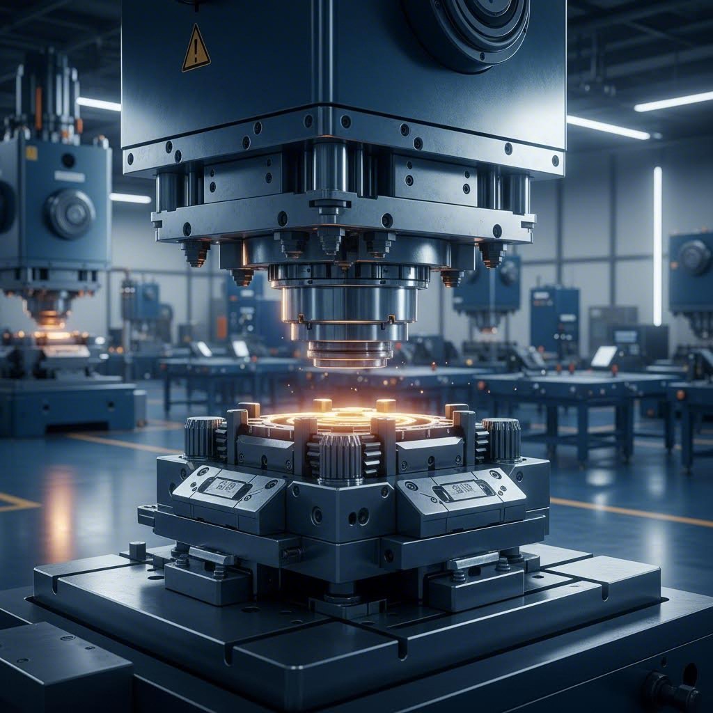
আপনি কখনও ভাবেছেন কীভাবে উৎপাদকরা অত্যন্ত নির্ভুলতার সাথে হাজার হাজার অভিন্ন ধাতব অংশ উৎপাদন করেন? এর উত্তর হলো ধাতু প্রেস ডাই—এক বিশেষায়িত যন্ত্রপাতি যা সমতল শীট ধাতুকে গাড়ির উপাদান থেকে শুরু করে ইলেকট্রনিক আবদ্ধকরণ পর্যন্ত সবকিছুতে রূপান্তরিত করে।
সহজ কথায়, ধাতু প্রেস ডাই হলো স্ট্যাম্পিং অপারেশনে ব্যবহৃত নির্ভুল প্রকৌশল-নির্মিত যন্ত্রপাতি, যা শীট ধাতুকে নির্দিষ্ট আকৃতি বা গঠনে আকৃতি দেয়, কাটে বা গঠন করে। এই শিল্পের বিশেষজ্ঞদের মতে, ফ্যাব্রিকেটর , একটি স্ট্যাম্পিং ডাই হলো "একটি বিশেষ, একক-প্রকারের নির্ভুল যন্ত্রপাতি যা শীট ধাতুকে কাঙ্ক্ষিত আকৃতি বা প্রোফাইলে কাটে ও গঠন করে।" এই যন্ত্রপাতিগুলির আকার অত্যন্ত বৈচিত্র্যময়—মাইক্রোইলেকট্রনিক্সের জন্য আপনার হাতের পালমে ধরা যায় এমন ছোট ডাই থেকে শুরু করে গাড়ির বডি প্যানেলের জন্য ব্যবহৃত ২০ ফুট লম্বা বিশাল কাঠামো পর্যন্ত।
যখন আপনি বিক্রয়ের জন্য একটি উচ্চমানের ডাই (Die) খুঁজছেন, তখন এই যন্ত্রগুলি কীভাবে কাজ করে তা বোঝা আপনার উৎপাদন প্রয়োজনীয়তার জন্য সঠিক পছন্দ করতে অত্যন্ত গুরুত্বপূর্ণ।
প্রেস ডাই (Press Die) অপারেশনের মৌলিক যান্ত্রিক ক্রিয়াকলাপ
একটি কুকিজ কাটার (Cookie Cutter) কে মাখন দিয়ে তৈরি করা মিষ্টির মিশ্রণের উপর রেখে চাপ দেওয়ার কথা কল্পনা করুন। প্রেস ডাইগুলি একই নীতির উপর ভিত্তি করে কাজ করে, কিন্তু অনেক বেশি বল ও নির্ভুলতার সাথে। ডাইটি একটি প্রেস মেশিনের সহযোগিতায় কাজ করে যা প্রয়োজনীয় বল প্রদান করে—অনেক সময় প্রতি মিনিটে ১,৫০০ স্ট্রোক পর্যন্ত গতিতে চক্রায়িত হয়।
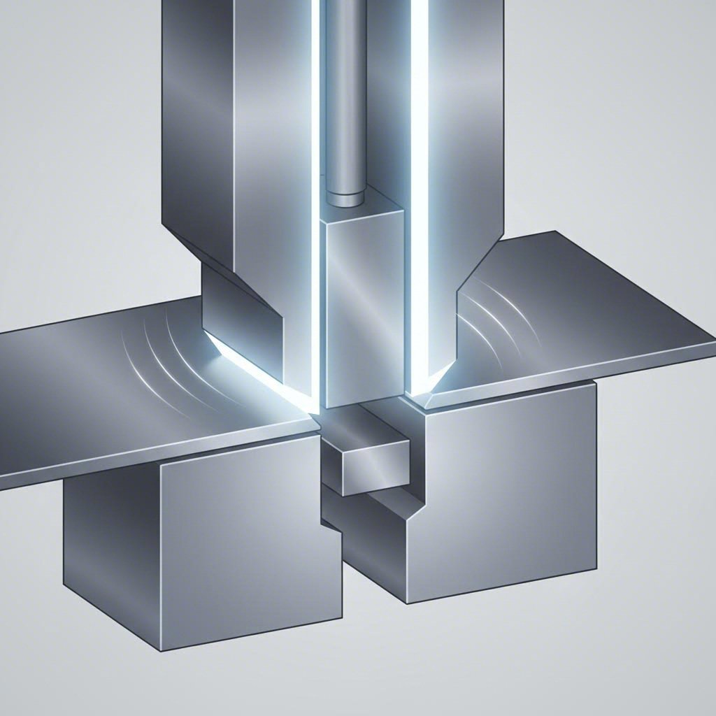
প্রতিটি প্রেস চক্রে যা ঘটে: প্রেস র্যাম (Ram) নিমেষে নিচে নেমে আসে এবং নিচের ডাই অংশে স্থাপিত শীট মেটালের উপর উপরের ডাই উপাদানগুলি নামিয়ে আনে। এই ক্রিয়াটি উপাদানটিকে কেটে ফেলে, বা এটিকে নির্দিষ্ট আকৃতিতে বাঁকিয়ে দেয়, অথবা উভয়টিই করে। স্ট্যাম্পিং (Stamping) কে একটি শীতল-আকৃতি গঠন (Cold-forming) অপারেশন হিসাবে বিবেচনা করা হয়, অর্থাৎ কোনও বাহ্যিক তাপ সচেতনভাবে প্রয়োগ করা হয় না। তবে, কাটিং ও আকৃতি গঠনের সময় ঘর্ষণজনিত তাপ উৎপন্ন হয় যা এতটাই বেশি হয় যে সম্পূর্ণ তৈরি হওয়া অংশগুলি প্রায়শই ডাই থেকে উত্তপ্ত অবস্থায় বেরিয়ে আসে।
প্রয়োজনীয় বল নির্ভর করে উপাদানের পুরুত্ব, অপারেশনের ধরন এবং পার্টের জটিলতার উপর। কাটিং অপারেশনগুলি ধাতুকে চাপের মুখে ফেলে যাতে সেটি ব্যর্থতার সীমায় পৌঁছায়, ফলে একটি বৈশিষ্ট্যপূর্ণ কিনারা তৈরি হয় যা অভিজ্ঞ অপারেটররা একটি স্বাক্ষরের মতো বুঝতে পারেন।
পাঞ্চ ও ডাইয়ের সম্পর্ক বোঝা
পাঞ্চ এবং ডাইয়ের মধ্যে সম্পর্ক প্রতিটি প্রেস ডাই অপারেশনের মূল ভিত্তি। এদেরকে একটি নির্ভুল পাজলের দুটি অংশ হিসেবে ভাবুন যারা নিখুঁতভাবে একসাথে কাজ করতে হবে।
পাঞ্চ হলো পুরুষ উপাদান—একটি কঠিন টুল যা কাজের টুকরোর উপাদানের মধ্যে বা তার মধ্য দিয়ে চাপ দেয়। ডাই হলো মহিলা উপাদান, যা পাঞ্চের সংস্পর্শে আসার সময় ধাতুকে আকৃতি দেওয়ার জন্য একটি গর্ত বা বিপরীত পৃষ্ঠ প্রদান করে। এই দুটি উপাদানের মধ্যে ছোট্ট ফাঁককে কাটিং ক্লিয়ারেন্স বলা হয়, যা অত্যন্ত গুরুত্বপূর্ণ। এই ক্লিয়ারেন্সটি সাধারণত উপাদানের পুরুত্বের শতকরা হারে প্রকাশ করা হয়, যেখানে স্ট্যান্ডার্ড কাটিং অপারেশনের জন্য প্রায় ১০ শতাংশ সবচেয়ে সাধারণ।
একটি ডাই কিনতে যাওয়ার সময় সর্বদা নিশ্চিত করুন যে পাঞ্চ এবং ডাই-এর ফাঁকগুলি আপনার নির্দিষ্ট উপাদানের প্রয়োজনীয়তা মেনে চলছে।
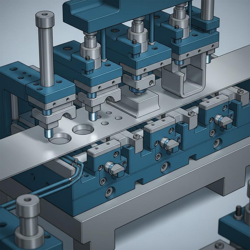
প্রতিটি কার্যকরী প্রেস ডাই কয়েকটি মূল উপাদানের সমন্বিত কাজের উপর নির্ভর করে:
- পাঞ্চ: পুরুষ কাটিং বা ফর্মিং টুল, যা কাজের টুকরোতে বল প্রয়োগ করে
- ডাই ব্লক: মহিলা উপাদান, যার মধ্যে ক্যাভিটি বা কাটিং এজ থাকে যা পাঞ্চকে গ্রহণ করে
- ডাই শুজ: ভারী ইস্পাতের প্লেট (উপরের এবং নিচের), যা অন্যান্য সমস্ত উপাদানের ভিত্তি হিসেবে কাজ করে এবং গুরুত্বপূর্ণ সমান্তরালতা বজায় রাখে
- স্ট্রিপার প্লেট: কাজের টুকরোকে সমতল রাখে এবং প্রতিটি অপারেশনের পরে পাঞ্চ থেকে এটিকে আলাদা করে
- গাইড পিন: নির্ভুল পোস্ট, যা প্রতিটি স্ট্রোকের সময় উপরের এবং নিচের ডাই অংশগুলির মধ্যে সঠিক সমান্তরালতা নিশ্চিত করে
ডাই শুজগুলির বিশেষ মনোযোগ দেওয়া উচিত, কারণ এগুলি স্থির অংশের গুণগত মানের অদৃশ্য নায়ক। এই ভারী ইস্পাতের প্লেটগুলি প্রতিটি উপাদানকে প্রতিটি স্ট্রোকের পর পর সঠিকভাবে সমান্তরাল রাখে, যার ফলে আপনার পাঞ্চ ও ডাইয়ের সম্পর্ক উৎপাদন চক্র জুড়ে স্থির থাকে। যদি ডাই শুজগুলি সঠিকভাবে রক্ষণাবেক্ষণ না করা হয়, তবে সর্বোত্তমভাবে নকশা করা প্রেস ডাইও অসঙ্গত ফলাফল উৎপন্ন করবে।
এই মৌলিক ধারণাগুলি বোঝা আপনাকে বিভিন্ন ধরনের প্রেস ডাই এবং তাদের নির্দিষ্ট প্রয়োগগুলি নিয়ে গভীরভাবে আলোচনা করার জন্য প্রয়োজনীয় ভিত্তি প্রদান করে—যা আমরা পরে আলোচনা করব।
ধাতু প্রেস ডাইয়ের প্রকারভেদ এবং তাদের প্রয়োগ
এখন যখন আপনি পাঞ্চ ও ডাই প্রেস সিস্টেমগুলি কীভাবে কাজ করে তা বুঝতে পেরেছেন, আপনি সম্ভবত ভাবছেন—কোন ধরনের ডাই রয়েছে এবং আপনার উৎপাদন চাহিদা অনুযায়ী কোনটি উপযুক্ত? এর উত্তর নির্ভর করে আপনার অংশের জটিলতা, উৎপাদন পরিমাণ এবং গুণগত মানের প্রয়োজনীয়তার উপর।
ডাই সেটগুলি কয়েকটি স্পষ্ট শ্রেণীতে আসে, প্রতিটি নির্দিষ্ট উৎপাদন পরিস্থিতির জন্য প্রকৌশলীদের দ্বারা নকশা করা হয় আপনি যদি লক্ষাধিক অভিন্ন ফাস্টেনার তৈরি করছেন বা জটিল এয়ারোস্পেস উপাদানের ছোট ব্যাচ তৈরি করছেন, তবে আপনার অ্যাপ্লিকেশনের জন্য উপযুক্ত ডাই টাইপ রয়েছে। আসুন প্রধান বিভাগগুলি বিশ্লেষণ করি যাতে আপনি আপনার অপারেশনের জন্য কোন পদ্ধতিটি সবচেয়ে উপযুক্ত তা চিহ্নিত করতে পারেন।
উচ্চ-পরিমাণ উৎপাদনের জন্য প্রোগ্রেসিভ ডাই
কল্পনা করুন একটি উৎপাদন লাইন যেখানে শীট মেটাল অবিচ্ছিন্ন স্ট্রিপ হিসাবে প্রবেশ করে এবং একক ডাই-এর মধ্যেই সম্পূর্ণ পার্টস হিসাবে বেরিয়ে আসে—এটিই হল প্রোগ্রেসিভ ডাইয়ের সৌন্দর্য।
প্রোগ্রেসিভ ডাইগুলিতে ধারাবাহিকভাবে সাজানো একাধিক স্টেশন থাকে, যেখানে প্রতিটি স্টেশন ধাতব স্ট্রিপটি টুলের মধ্য দিয়ে এগিয়ে যাওয়ার সময় একটি নির্দিষ্ট অপারেশন সম্পাদন করে। প্রতিটি প্রেস স্ট্রোকের সময় স্ট্রিপটি একটি নির্দিষ্ট দূরত্ব (যাকে পিচ বলা হয়) এগিয়ে যায় এবং প্রতিটি স্টেশন একসাথে তার নির্ধারিত কাজ সম্পাদন করে। প্রথম স্টেশনটি সাইটিংয়ের জন্য পাইলট হোল পাঞ্চ করতে পারে, দ্বিতীয়টি কাটআউট তৈরি করতে পারে, তৃতীয়টি একটি বেন্ড গঠন করতে পারে এবং চূড়ান্ত স্টেশনটি সম্পূর্ণ পার্টটিকে স্ট্রিপ থেকে আলাদা করে কেটে নিতে পারে।
এই অবিচ্ছিন্ন স্ট্রিপ ফিডিং পদ্ধতি উচ্চ-পরিমাণ উৎপাদনের জন্য অসাধারণ দক্ষতা প্রদান করে। প্রতি মিনিটে অংশের সংখ্যা বিস্ময়করভাবে বৃদ্ধি পেতে পারে, কারণ প্রতিটি স্ট্রোকে একটি সম্পূর্ণ উপাদান তৈরি হয় এবং একইসাথে অন্যান্য সমস্ত স্টেশনের মধ্য দিয়ে কাজ এগিয়ে যায়। গাড়ির ব্র্যাকেট, বৈদ্যুতিক কানেক্টর এবং ঘরোয়া যন্ত্রপাতির উপাদানগুলি সাধারণত প্রোগ্রেসিভ ডাই সেট থেকে উৎপন্ন হয়।
এর বিনিময়ে কী পাওয়া যায়? প্রোগ্রেসিভ ডাই ডিজাইন ও নির্মাণে উল্লেখযোগ্য প্রাথমিক বিনিয়োগ প্রয়োজন। তবে যখন উৎপাদন পরিমাণ খরচ ন্যায্যতা প্রদান করে, তখন তাদের দক্ষতার সমতুল্য অন্য কোনো পদ্ধতি খুব কমই পাওয়া যায়। মুদ্রা উৎপাদনে ব্যবহৃত কয়েন প্রেস ডাইগুলিতে প্রায়শই একই ধরনের প্রোগ্রেসিভ নীতি প্রয়োগ করা হয়, যাতে মিন্টিং অপারেশনগুলির জন্য প্রয়োজনীয় সুস্থির ও উচ্চ-পরিমাণ আউটপুট অর্জন করা যায়।
জটিল অংশের জ্যামিতির জন্য ট্রান্সফার ডাই
যখন আপনার অংশটি প্রোগ্রেসিভ স্ট্যাম্পিং-এর জন্য অত্যধিক জটিল হয়ে ওঠে, অথবা যখন উপাদান স্ট্রিপটি অপ্রয়োজনীয়ভাবে বড় ও অসুবিধাজনক হয়ে ওঠে, তখন কী হবে? ট্রান্সফার ডাই একটি নির্ভুল সমাধান প্রদান করে।
প্রগ্রেসিভ অপারেশনের বিপরীতে, যেখানে অংশগুলি ক্যারিয়ার স্ট্রিপের সাথে সংযুক্ত থাকে, ট্রান্সফার ডাইগুলি আলাদা ব্ল্যাঙ্কগুলির সাথে কাজ করে। যান্ত্রিক আঙুল বা স্বয়ংক্রিয়করণ সিস্টেমগুলি প্রতিটি ওয়ার্কপিসকে স্টেশন থেকে স্টেশনে শারীরিকভাবে স্থানান্তরিত করে। এই পদ্ধতিটি গভীর ড্র এবং আরও জটিল ফর্মিং অপারেশনগুলি সম্ভব করে তোলে, এবং এমন অংশগুলিও তৈরি করা সম্ভব হয় যা স্ট্রিপ উপাদানের সাথে সংযুক্ত থাকার সময় অন্যথায় উৎপাদন করা সম্ভব হত না।
অটোমোটিভ বডি প্যানেল বা ব্যাপক ফর্মিং অপারেশন প্রয়োজন করে এমন বৃহত্তর অংশগুলি উৎপাদন করার সময় ট্রান্সফার সিস্টেমগুলি চমকপ্রদ কার্যকারিতা প্রদর্শন করে। স্টেশনগুলির মধ্যে অংশগুলিকে স্বাধীনভাবে নিয়ন্ত্রণ করার ক্ষমতা এমন সম্ভাবনা খোলে যা প্রগ্রেসিভ ডাইগুলি সাধারণত অর্জন করতে পারে না।
কম্পাউন্ড বনাম কম্বিনেশন ডাই: ব্যাখ্যা
জটিল শোনাচ্ছে? এটা হতে হবে না। কম্পাউন্ড এবং কম্বিনেশন ডাইয়ের মধ্যে পার্থক্যটি আসলে খুব সহজ— যখন আপনি এদের মৌলিক নীতিগুলি বুঝতে পারেন।
কম্পাউন্ড ডাইগুলি একটি একক প্রেস স্ট্রোকে একাধিক কাটিং অপারেশন সম্পাদন করে। চিন্তা করুন একটি ডাই-এর কথা যা একই সাথে অভ্যন্তরীণ গর্তগুলি পাঞ্চ করছে এবং বাহ্যিক পরিধিকে ব্ল্যাঙ্ক করছে—সবকিছু একটি একক গতিতে। পাঞ্চটি একটি অপারেশনের জন্য ডাই হিসেবে কাজ করে, আবার ডাইটি অন্য একটি অপারেশনের জন্য পাঞ্চ হিসেবে কাজ করে। এই চতুর ব্যবস্থাটি অত্যন্ত সমতল অংশ এবং উৎকৃষ্ট কিনারা গুণগত মান উৎপাদন করে, ফলে কম্পাউন্ড ডাইগুলি ওয়াশার, গ্যাসকেট এবং অনুরূপ উচ্চ সমতলতা সহনসীমা প্রয়োজন করা উপাদানগুলির জন্য আদর্শ।
অপরদিকে, কম্বিনেশন ডাইগুলি কাটিং এবং ফর্মিং উভয় অপারেশনই একসাথে সম্পাদন করে। একটি একক স্ট্রোকে বাহ্যিক আকৃতিটি ব্ল্যাঙ্ক করা হতে পারে এবং একই সময়ে কাজের টুকরোতে বেঁকানো, ড্রয়িং বা এমবসিং করা হতে পারে। এই বহুমুখিতা প্রয়োজনীয় ডাই সেটগুলির সংখ্যা কমিয়ে দেয় এবং মধ্যম জটিলতার অংশগুলির উৎপাদন প্রক্রিয়াকে সরলীকৃত করে।
ফর্মিং ডাইগুলি বেঁকানো ও আকৃতি দেওয়ার কাজের জন্য বিশেষভাবে ডিজাইন করা হয়, যা সমতল ব্ল্যাঙ্কগুলিকে ত্রিমাত্রিক উপাদানে রূপান্তরিত করে। সরল V-বেন্ড থেকে শুরু করে জটিল ফ্ল্যাঞ্জ পর্যন্ত—এই প্রেস কাটিং ডাইগুলি স্ট্যাম্পড অংশগুলির কার্যকারিতা প্রদানকারী জ্যামিতিক বৈশিষ্ট্যগুলি তৈরি করে। একইভাবে, হট-ফর্মিং অপারেশনে ব্যবহৃত ফোর্জ ডাই উচ্চ তাপমাত্রায় একই নীতিগুলি প্রয়োগ করে, যা তাপীয় প্রক্রিয়াকরণ প্রয়োজন করে এমন উপকরণগুলির জন্য উপযুক্ত।
ব্ল্যাঙ্কিং ডাইগুলি শীট স্টক থেকে সমতল আকৃতি কাটার কাজে কেবলমাত্র নিযুক্ত থাকে, অন্যদিকে পিয়ার্সিং ডাইগুলি অভ্যন্তরীণ ছিদ্র ও খোলা সৃষ্টি করে। উভয় ধরনের ডাই-এর ক্ষেত্রেই পাঞ্চ ও ডাইয়ের মধ্যে নির্ভুল ক্লিয়ারেন্স বজায় রাখা আবশ্যিক যাতে পরিষ্কার কিনারা এবং সুসঙ্গত মাত্রা পাওয়া যায়।
| ডাই টাইপ | অপারেশন পদ্ধতি | সর্বোত্তম প্রয়োগ | উৎপাদন পরিমাণ উপযোগিতা |
|---|---|---|---|
| প্রগতিশীল মর | বহু স্টেশনের মধ্য দিয়ে অবিরাম স্ট্রিপ ফিডিং | ছোট থেকে মাঝারি আকারের বহু-বৈশিষ্ট্যযুক্ত অংশ | উচ্চ পরিমাণ (১,০০,০০০+ পার্ট) |
| ট্রান্সফার ডাইস | স্টেশনগুলির মধ্যে ব্যক্তিগত ব্ল্যাঙ্কগুলি স্থানান্তরিত হয় | বড় বা গভীরভাবে গঠিত অংশ | মাঝারি থেকে উচ্চ পরিমাণ |
| Compound dies | একক স্ট্রোকে একাধিক কাটিং অপারেশন | উৎকৃষ্ট কিনারা গুণগত মান প্রয়োজনীয় সমতল অংশ | মাঝারি থেকে উচ্চ পরিমাণ |
| কম্বিনেশন ডাই | একক স্ট্রোকে কাটিং ও ফর্মিং | মিশ্র অপারেশনযুক্ত মাঝারি জটিলতার অংশ | কম থেকে মাঝারি পরিমাণ |
| ব্ল্যাঙ্কিং ডাই | বাইরের পরিধির আকৃতি কাটা | দ্বিতীয়ক অপারেশনের জন্য সমতল খালি অংশ | সমস্ত ভলিউম স্তর |
| ফর্মিং ডাই | উপাদান বাঁকানো, টানা বা আকৃতি দেওয়া | ত্রিমাত্রিক অংশের বৈশিষ্ট্য | সমস্ত ভলিউম স্তর |
| ছিদ্রের মুর্তি | অভ্যন্তরীণ গর্ত এবং কাটআউট তৈরি করা | নির্ভুল গর্তের প্যাটার্ন প্রয়োজনীয় অংশ | সমস্ত ভলিউম স্তর |
সঠিক ডাই ধরন নির্বাচন করতে হলে অংশের জটিলতা, উৎপাদন প্রয়োজনীয়তা এবং বাজেট সীমাবদ্ধতা—এই তিনটি বিষয়ের ভারসাম্য বজায় রাখতে হয়। কিন্তু ডাই নির্বাচন শুধুমাত্র একটি শ্রেণি নির্বাচনের মধ্যেই সীমাবদ্ধ থাকে না—আপনার টুলিং নির্মাণে ব্যবহৃত উপকরণগুলোও কার্যকারিতা ও দীর্ঘস্থায়িত্ব নির্ধারণে সমানভাবে গুরুত্বপূর্ণ ভূমিকা পালন করে।
ডাই-এর উপকরণ এবং নির্বাচনের মাপদণ্ড
আপনি আপনার অ্যাপ্লিকেশনের জন্য সঠিক ডাই ধরন নির্বাচন করেছেন—কিন্তু সেই ডাইটি আসলে কোন উপাদান দিয়ে তৈরি হওয়া উচিত? এই প্রশ্নটি প্রায়শই মিলিয়ন সাইকেল পর্যন্ত স্থায়ী টুলিং এবং প্রাথমিকভাবে ব্যর্থ হওয়া ডাইগুলোর মধ্যে পার্থক্য নির্ধারণ করে। উপকরণ নির্বাচন প্রক্রিয়ায় কঠোরতা, ক্ষয় প্রতিরোধ ক্ষমতা এবং শক্তিশালীতা—এই তিনটি বিষয়ের ভারসাম্য বজায় রাখতে হয়, যার সাথে আপনার নির্দিষ্ট উৎপাদন প্রয়োজনীয়তাগুলোও বিবেচনা করতে হয়।
ডাই উপকরণগুলিকে একটি স্পেকট্রামের মতো ভাবুন। এক প্রান্তে আপনি নরম, কিন্তু শক্তিশালী ইস্পাত পাবেন যা চিপিং-এর বিরুদ্ধে প্রতিরোধ করে, কিন্তু দ্রুত ক্ষয়প্রাপ্ত হয়। অন্য প্রান্তে কার্বাইডের মতো অত্যন্ত কঠিন উপকরণ রয়েছে যা অসাধারণ ক্ষয় প্রতিরোধ ক্ষমতা প্রদান করে, কিন্তু আঘাতের সময় ভঙ্গুর হতে পারে। এই স্পেকট্রামের সঠিক অবস্থান নির্বাচন করা আপনার টুলিং ডাইয়ের কার্যকারিতা এবং মোট মালিকানা খরচ উভয়েরই নির্ধারক।
ডাই নির্মাণের জন্য টুল স্টিল গ্রেড
প্রেস অ্যাপ্লিকেশনের জন্য ডাই তৈরি করার সময়, টুল স্টিলগুলি এখনও অধিকাংশ উৎপাদনকারীর জন্য প্রধান কাজকর্মের উপকরণ । এই বিশেষায়িত মিশ্র ধাতুগুলি যথেষ্ট মূল্যে বৈশিষ্ট্যের একটি চমৎকার ভারসাম্য প্রদান করে। নিম্নলিখিত সাধারণ গ্রেডগুলি সম্পর্কে আপনার যা জানা প্রয়োজন:
- D2 টুল স্টিল: মেশিন ডাইয়ের জন্য সবচেয়ে জনপ্রিয় পছন্দ, D2 উচ্চ ক্ষয় প্রতিরোধ ক্ষমতা এবং ভালো শক্তি প্রদান করে। এর ১১-১৩% ক্রোমিয়াম সামগ্রী মধ্যম মাত্রার কর্মোদ্দীপক প্রতিরোধ প্রদান করে, যখন কঠিনতা স্তর ৫৮-৬২ HRC পর্যন্ত পৌঁছায়। মাঝারি পুরুত্ব পর্যন্ত উপকরণের উপর ব্ল্যাঙ্কিং এবং পিয়ার্সিং অপারেশনের জন্য এটি আদর্শ।
- A2 টুল স্টিল: বায়ু-শক্তিকরণ ইস্পাত যা D2-এর তুলনায় সামান্য নিম্নতর কঠোরতা (৫৭-৬২ HRC) সহ উত্তম টাগনেস প্রদান করে। তাপ চিকিৎসার সময় অত্যুত্তম মাত্রিক স্থিতিশীলতা A2-কে জটিল ডাই জ্যামিতির জন্য প্রিয় করে তোলে, যেখানে বিকৃতি ন্যূনতম রাখা আবশ্যিক।
- O1 টুল স্টিল: একটি তেল-শক্তিকরণ গ্রেড যা নিম্ন-পরিমাণ অ্যাপ্লিকেশনের জন্য ভালো যন্ত্রকরণ সামর্থ্য এবং যথেষ্ট কঠোরতা (৫৭-৬১ HRC) প্রদান করে। O1-এর দাম D2 বা A2-এর তুলনায় কম, ফলে প্রোটোটাইপ টুলিং বা সংক্ষিপ্ত উৎপাদন চক্রের জন্য এটি অর্থনৈতিক।
- S7 টুল স্টিল: আঘাত-প্রতিরোধী ইস্পাত যা আঘাত-সম্পর্কিত অ্যাপ্লিকেশনের জন্য ডিজাইন করা হয়েছে। যখন আপনার প্রেস অপারেশনের জন্য ডাই ভারী ব্ল্যাঙ্কিং বা আঘাত-ভারিত লোড সৃষ্টিকারী উপকরণ প্রক্রিয়া করে, তখন S7-এর উত্তম টাগনেস বিপর্যয়কারী ব্যর্থতা রোধ করে।
- M2 হাই-স্পিড স্টিল: যখন ক্ষয়কারী উপকরণ প্রক্রিয়া করা হয় বা উচ্চ গতিতে কাজ করা হয়, তখন M2 ঐ তাপমাত্রায় তার কঠোরতা বজায় রাখে যেখানে সাধারণ টুল স্টিলগুলি তা করতে পারে না। এটি ঘর্ষণজনিত তাপ সৃষ্টিকারী প্রগ্রেসিভ ডাই কম্পোনেন্টগুলিতে সাধারণত ব্যবহৃত হয়।
এই গ্রেডগুলির মধ্যে নির্বাচনটি আপনার নির্দিষ্ট অ্যাপ্লিকেশনের উপর ব্যাপকভাবে নির্ভর করে। পাতলা অ্যালুমিনিয়াম প্রক্রিয়াজাত করতে ভিন্ন উপাদান বৈশিষ্ট্য প্রয়োজন, যা ঘন স্টেইনলেস স্টিলের মধ্য দিয়ে পাঞ্চ করার চেয়ে আলাদা। আপনার টুলিং সরবরাহকারীকে উপাদানের পুরুত্ব, ধরন এবং উৎপাদন প্রয়োজনীয়তা মূল্যায়ন করে একটি নির্দিষ্ট গ্রেড সুপারিশ করা উচিত।
কার্বাইড ইনসার্টগুলি যখন অর্থনৈতিকভাবে যুক্তিসঙ্গত হয়
কল্পনা করুন, কয়েক মিলিয়ন সাইকেল ধরে একটি ধাতব ডাই সেট চালানো হচ্ছে যেখানে কাটিং উপাদানগুলি প্রতিস্থাপন করা হচ্ছে না। কার্বাইড ইনসার্টগুলি এটি সম্ভব করে তোলে—কিন্তু এদের সাথে উল্লেখযোগ্য কিছু বাণিজ্যিক বিনিময় জড়িত, যা আপনি বুঝতে চাইবেন।
কার্বাইড (কোবাল্ট বাইন্ডারে টাংস্টেন কার্বাইড) প্রায় ৯০ HRA কঠোরতা অর্জন করে, যা যেকোনো টুল স্টিলের চেয়ে উল্লেখযোগ্যভাবে বেশি। এই চরম কঠোরতা সরাসরি ডাই-জীবন বৃদ্ধির দিকে নিয়ে যায়—অনেক সময় তুলনামূলক স্টিল উপাদানগুলির চেয়ে ১০ থেকে ২০ গুণ বেশি। বছরে মিলিয়ন মিলিয়ন পার্টস উৎপাদনকারী উচ্চ-খণ্ড স্বয়ত্ব বা ইলেকট্রনিক্স অ্যাপ্লিকেশনগুলির ক্ষেত্রে, কার্বাইড ইনসার্টগুলি প্রাথমিক উচ্চ খরচ সত্ত্বেও প্রায়শই অর্থনৈতিকভাবে শ্রেষ্ঠ প্রমাণিত হয়।
তবে, কার্বাইডের কঠোরতা এর ভঙ্গুরতার সাথে যুক্ত। এই উপকরণগুলি আঘাতের লোড বা অসমান্তরালতা ভালোভাবে সহ্য করতে পারে না। একটি কার্বাইড পাঞ্চ যদি ডাই-এর সাথে কোণে আঘাত করে—যা একটি ইস্পাত পাঞ্চ টিকে যেতে পারে—তবে তা তৎক্ষণাৎ ভেঙে যেতে পারে। এই বাস্তবতা নির্দেশ করে যে, কার্বাইড সর্বোত্তমভাবে ভালোভাবে রক্ষণাবেক্ষণ করা প্রেসগুলিতে কাজ করে, যেখানে সঠিক সমান্তরালতা বজায় রাখা হয় এবং যেখানে অন্তর্ভুক্তি বা কঠিন স্থান ছাড়াই সুসংগত উপকরণ প্রক্রিয়াকরণ করা হয়।
অনেক উৎপাদনকারী একটি সংমিশ্রণ পদ্ধতি গ্রহণ করেন, যেখানে শুধুমাত্র সর্বোচ্চ ক্ষয়প্রবণ অঞ্চলগুলিতে কার্বাইড ইনসার্ট ব্যবহার করা হয়, অন্যদিকে মেশিন ডাই-এর অবশিষ্ট অংশ টুল স্টিল দিয়ে তৈরি করা হয়। এই কৌশলটি কার্বাইডের দীর্ঘস্থায়ীত্বের সুবিধাগুলি অর্জন করে এবং একইসাথে খরচ ও ভঙ্গুরতা সংক্রান্ত চিন্তাগুলি নিয়ন্ত্রণ করে।
ডাই-এর আয়ু বৃদ্ধি করে এমন পৃষ্ঠ চিকিৎসা
যদি আপনি ব্যয়বহুল কার্বাইড-এ রূপান্তর না করেই আপনার বিদ্যমান টুল স্টিল ডাইগুলির কার্যকারিতা উল্লেখযোগ্যভাবে উন্নত করতে পারেন, তবে কী হবে? পৃষ্ঠ চিকিৎসা ও কোটিংগুলি এই সম্ভাবনাটি সঠিকভাবে প্রদান করে।
নাইট্রাইডিং পদ্ধতিতে ডাইয়ের পৃষ্ঠে নাইট্রোজেন বিস্তৃত করা হয়, যার ফলে প্রায় ০.০০১ থেকে ০.০২০ ইঞ্চি গভীরতা বিশিষ্ট একটি কঠিন পৃষ্ঠস্তর তৈরি হয়। এই চিকিত্সার ফলে পৃষ্ঠের কঠিনতা ৬৫–৭০ HRC-এ পৌঁছায়, অথচ ফাটল প্রতিরোধী শক্তিশালী কোর বজায় থাকে। নাইট্রাইড করা ডাইগুলি পৃষ্ঠের আংশিক আঁচড়ানো (গ্যালিং) ঘটতে পারে এমন ফর্মিং অ্যাপ্লিকেশনগুলিতে উৎকৃষ্ট কাজ করে।
শারীরিক বাষ্পীভবন অধঃক্ষেপণ (PVD) কোটিংগুলি পৃষ্ঠের কার্যকারিতা পরিবর্তন করে এমন পাতলা সেরামিক স্তর যোগ করে:
- TiN (টাইটানিয়াম নাইট্রাইড): পরিচিত সোনালী রঙের কোটিং পৃষ্ঠের কঠিনতা বৃদ্ধি করে এবং ঘর্ষণ হ্রাস করে। পাঞ্চ ও ফর্মিং পৃষ্ঠের জন্য এটি একটি চমৎকার সাধারণ-উদ্দেশ্য চিকিত্সা।
- TiCN (টাইটানিয়াম কার্বোনাইট্রাইড): TiN-এর চেয়ে কঠিন এবং ভালো ক্ষয় প্রতিরোধী ক্ষমতা সম্পন্ন। নীল-ধূসর রঙের কোটিং ঘর্ষণজনিত উপকরণের অ্যাপ্লিকেশনগুলিতে ভালো কাজ করে।
- TiAlN (টাইটানিয়াম অ্যালুমিনিয়াম নাইট্রাইড): অত্যুত্তম তাপ প্রতিরোধী ক্ষমতার জন্য এই কোটিংটি উচ্চ গতিতে কাজ করার জন্য বা যেসব উপকরণ প্রক্রিয়াকরণের সময় উল্লেখযোগ্য ঘর্ষণ সৃষ্টি করে, সেগুলির জন্য আদর্শ।
এই কোটিংগুলি সাধারণত মাত্র ২-৫ মাইক্রন পুরু—মানব চুলের চেয়েও পাতলা—তবুও এগুলি চাহিদাপূর্ণ অ্যাপ্লিকেশনগুলিতে ডাই-এর আয়ু দ্বিগুণ বা ত্রিগুণ করতে পারে। মূল কথা হল আপনার নির্দিষ্ট ক্ষয় ব্যবস্থার সাথে কোটিং নির্বাচনের সঠিক মিল ঘটানো। অ্যাব্রেজিভ ক্ষয়ের জন্য যে সমাধানগুলি প্রয়োজন, সেগুলি আডহেসিভ ক্ষয় বা গ্যালিং-এর জন্য প্রয়োজনীয় সমাধানগুলি থেকে ভিন্ন।
উপকরণ নির্বাচন বোঝার মাধ্যমে আপনি সেই টুলিং নির্দিষ্ট করার ভিত্তি অর্জন করেন যা কার্যকারিতা এবং বাজেট উভয় প্রয়োজনীয়তা পূরণ করে। কিন্তু সর্বোত্তম উপকরণগুলিও খারাপভাবে ডিজাইন করা ডাই-কে বাঁচাতে পারবে না—যা আমাদের একটি গুরুত্বপূর্ণ প্রশ্নের দিকে নিয়ে যায়: কোন প্রকৌশল মৌলিক নীতিগুলি অসাধারণ টুলিংকে গড় ফলাফল থেকে পৃথক করে?
ডাই ডিজাইন প্রকৌশল মৌলিক নীতিসমূহ
আপনি সঠিক ডাই টাইপ নির্বাচন করেছেন এবং প্রিমিয়াম উপকরণগুলি নির্দিষ্ট করেছেন—তবুও কিছু ডাই কেন অসঙ্গতিপূর্ণ পার্টস তৈরি করে বা অকালে ক্ষয় হয়? এর উত্তরটি প্রায়শই সেই প্রকৌশলগত সিদ্ধান্তগুলিতে লুকিয়ে থাকে, যা যেকোনো ইস্পাত কাটার আগেই গৃহীত হয়। কার্যকরী ডাই প্রেস ডিজাইন হলো পদার্থবিজ্ঞান, উপকরণ বিজ্ঞান এবং ব্যবহারিক উৎপাদন অভিজ্ঞতার একটি সমন্বিত পদ্ধতি, যেখানে প্রতিটি উপাদান সামঞ্জস্যপূর্ণভাবে কাজ করে।
ডাই ডিজাইনকে একটি জটিল ধাঁধার সমাধান হিসেবে ভাবুন, যেখানে প্রতিটি টুকরো অন্য সমস্ত টুকরোকে প্রভাবিত করে। আপনি যে ক্লিয়ারেন্স নির্বাচন করেন, তা কিনারার গুণগত মানকে প্রভাবিত করে। আপনার স্ট্রিপ লেআউট উপকরণ ব্যবহারের হারকে প্রভাবিত করে। স্প্রিংব্যাক কম্পেনসেশন নির্ধারণ করে যে বাঁকানো পার্টসগুলি কি মুদ্রিত টলারেন্সের সাথে মেনে চলছে কিনা। একটি মাত্র উপাদানের ভুল সমগ্র উৎপাদন প্রক্রিয়ায় ধারাবাহিকভাবে প্রভাব ফেলে। আসুন সেই গুরুত্বপূর্ণ প্রকৌশলগত নীতিগুলি অন্বেষণ করি যা চমৎকার টুলিং-কে গড়া ফলাফল থেকে পৃথক করে।
উপকরণ প্রবাহ বিশ্লেষণ এবং ফর্মিং বিবেচনা
যখন আপনি পাতলা ধাতুর পাত (শীট মেটাল) বাঁকান, টানেন বা গঠন করেন, তখন আপনি উপাদানটিকে এমন কিছু করতে বলছেন যা এটি স্বাভাবিকভাবে করতে চায় না—অর্থাৎ সমতল রূপ থেকে ত্রিমাত্রিক আকৃতিতে নিজেকে পুনর্বিন্যাস করা। এই প্রক্রিয়াগুলোর সময় উপাদান কীভাবে প্রবাহিত হয় তা বোঝা সফল ফর্ম ডাই ডিজাইনের জন্য মৌলিক।
টানার প্রক্রিয়ার সময়, ধাতুকে কিছু অঞ্চলে প্রসারিত হতে হয় এবং অন্য কিছু অঞ্চলে সংকুচিত হতে হয়। একটি সমতল বৃত্তাকার ব্ল্যাঙ্ককে একটি কাপ-আকৃতির মধ্যে টানার কথা কল্পনা করুন। বাইরের প্রান্তের উপাদানটি অন্তর্মুখীভাবে টানা হওয়ার সময় পরিধীয়ভাবে সংকুচিত হতে হয়, অন্যদিকে কাপের দেয়াল গঠনকারী উপাদানটি প্রসারিত হয়। যদি সংকোচন অত্যধিক হয়, তবে ভাঁজ বা কুঁচকে যাওয়ার চিহ্ন দেখা যায়। আবার, যদি প্রসারণ উপাদানের সীমা অতিক্রম করে, তবে ফাটল দেখা দেয়।
অভিজ্ঞ প্রকৌশলীরা যেকোনো টুল স্টিল কাটার আগে এই প্রবাহ প্যাটার্নগুলি বিশ্লেষণ করেন। তারা ড্র অনুপাত গণনা করেন, সম্ভাব্য সমস্যার এলাকাগুলি চিহ্নিত করেন এবং ড্র বিডস সহ বৈশিষ্ট্যগুলি ডিজাইন করেন যা উপকরণের গতি নিয়ন্ত্রণ করে। ড্র বিডস হল বাইন্ডার পৃষ্ঠের উত্থিত রিজগুলি যা ঘর্ষণ যোগ করে এবং উপকরণটি ডাই ক্যাভিটিতে কত দ্রুত প্রবেশ করছে তা নিয়ন্ত্রণ করে—এদের ধাতুর প্রবাহের জন্য ট্রাফিক কন্ট্রোলার হিসেবে ভাবুন।
জটিল প্রেসিং ডাই জ্যামিতির ক্ষেত্রে, প্রকৌশলীরা উপকরণের পাতলা হওয়ার বিষয়টিও বিবেচনা করেন। গঠনকালীন ধাতু প্রসারিত হওয়ার সময় এটি পাতলা হয়ে যায়। অত্যধিক পাতলা হওয়া সম্পূর্ণ অংশটিকে দুর্বল করে দেয় এবং ব্যবহারকালীন ব্যর্থতার কারণ হতে পারে। উপযুক্ত ডাই ডিজাইন তন্ত্রটিকে আরও সমানভাবে বণ্টন করে, যাতে অংশটির সমগ্র অংশে পাতলা হওয়া গ্রহণযোগ্য সীমার মধ্যে থাকে।
সঠিক বেঁকিংয়ের জন্য স্প্রিংব্যাক কম্পেনসেশন
আপনি কখনও একটি ধাতব স্কেল বাঁকানোর চেষ্টা করেছেন, কিন্তু ছেড়ে দেওয়ার পর এটি আংশিকভাবে মূল আকৃতির দিকে ফিরে আসতে দেখেছেন? এটাই হল স্প্রিংব্যাক—এবং এটি শীট মেটাল ডাই ডিজাইনের সবচেয়ে চ্যালেঞ্জিং দিকগুলির মধ্যে একটি।
প্রতিটি ধাতুর বিকৃতির একটি স্থিতিস্থাপক উপাদান থাকে। যখন আপনি কোনো উপাদানকে এর যিল্ড পয়েন্টের বাইরে বাঁকান, তখন এটি স্থায়ীভাবে বাঁক নেয়, কিন্তু চাপ কমানোর পরও কিছুটা স্থিতিস্থাপক পুনরুদ্ধার ঘটে। উপাদানের যিল্ড শক্তি যত বেশি হবে, এই প্রভাবটি তত বেশি প্রকট হবে। গাড়ি নির্মাণে ব্যবহৃত উন্নত উচ্চ-শক্তি স্টিলগুলি তাদের গঠিত অবস্থান থেকে কয়েক ডিগ্রি পিছনে ফিরে আসতে পারে।
স্প্রিংব্যাক কমানোর জন্য জানতে জানতে অতিরিক্ত বাঁকানো প্রয়োজন। যদি আপনার সম্পূর্ণ পার্টটির ৯০-ডিগ্রি কোণ প্রয়োজন হয়, তবে আপনার ফর্ম ডাইটি এটিকে ৮৭ বা ৮৮ ডিগ্রিতে বাঁকাতে পারে, যাতে স্প্রিংব্যাক এটিকে লক্ষ্য কোণে নিয়ে আসে। সঠিক কম্পেনসেশন পরিমাণ নির্ধারণ করতে হলে উপাদানের বৈশিষ্ট্য, বেন্ড ব্যাসার্ধ এবং গঠন পদ্ধতি সম্পর্কে ভালোভাবে জানা আবশ্যক।
ইঞ্জিনিয়াররা স্প্রিংব্যাক নিয়ন্ত্রণের জন্য একাধিক কৌশল ব্যবহার করেন:
- ওভারবেন্ড: লক্ষ্য কোণের চেয়ে বেশি বাঁকানো, যাতে স্প্রিংব্যাক পার্টটিকে নির্দিষ্ট মানে ফিরিয়ে আনে
- কয়েনিং: বেন্ড লাইনে উচ্চ স্থানীয় চাপ প্রয়োগ করে উপাদানটিকে আরও স্থায়ীভাবে সেট করা
- বটমিং: প্লাস্টিক বিকৃতি সর্বাধিক করার জন্য পাঞ্চটিকে ডাই ক্যাভিটিতে সম্পূর্ণরূপে চাপা
- স্ট্রেচ বেন্ডিং: গঠনকরণের সময় টান প্রয়োগ করে স্থিতিস্থাপক উপাদানটি হ্রাস করা
আধুনিক সিমুলেশন টুলগুলি শারীরিক ডাই তৈরি করার আগেই স্প্রিংব্যাক আচরণের পূর্বাভাস দেয়, যার ফলে প্রকৌশলীরা সমস্যাগুলি ট্রাই-আউটের সময় আবিষ্কার না করে প্রাথমিক ডিজাইনেই কম্পেনসেশন অন্তর্ভুক্ত করতে পারেন।
ক্লিয়ারেন্স গণনা এবং তার পার্ট মানের উপর প্রভাব
আপনার পাঞ্চ ও ডাইয়ের মধ্যবর্তী ফাঁক—কাটিং ক্লিয়ারেন্স—ছোট বিষয়ের মতো মনে হতে পারে, কিন্তু এটি প্রান্তের মান, টুলের আয়ু এবং মাত্রাগত নির্ভুলতা মৌলিকভাবে নির্ধারণ করে। এটি ভুল হলে, আপনি অত্যধিক বার্স, প্রারম্ভিক ক্ষয় বা স্পেসিফিকেশন অনুযায়ী না হওয়া পার্টগুলির মুখোমুখি হবেন।
একটি মৌলিক প্রকৌশলী নীতি হিসাবে, অপটিমাল কাটিং ক্লিয়ারেন্স সাধারণত উপাদানের পুরুত্বের শতকরা হার হিসাবে প্রকাশ করা হয়—সাধারণত উপাদানের ধরন এবং প্রার্থিত প্রান্তের বৈশিষ্ট্যের উপর নির্ভর করে প্রতি পাশে ৫% থেকে ১৫% পর্যন্ত হয়ে থাকে।
অত্যন্ত কম ক্লিয়ারেন্স পাঞ্চ ও ডাইকে অপ্রয়োজনীয়ভাবে বেশি কাজ করতে বাধ্য করে। কাটিং এজগুলো অত্যধিক চাপের সম্মুখীন হয়, যার ফলে ক্ষয় ত্বরান্বিত হয়। অংশগুলোতে উপযুক্ত ফ্র্যাকচার জোন ছাড়াই পলিশ করা ধার দেখা যেতে পারে এবং স্ট্রিপিং বল ব্যাপকভাবে বৃদ্ধি পায়।
অত্যধিক ক্লিয়ারেন্স ভিন্ন ধরনের সমস্যা সৃষ্টি করে। উপাদানটি পরিষ্কারভাবে কাটা না হয়ে টানা হওয়ার কারণে বার্সগুলো স্পষ্টভাবে প্রকট হয়। ছিদ্রের ব্যাস টলারেন্সের বাইরে বৃদ্ধি পায় এবং ধারের গুণগত মান ক্ষুণ্ণ হয়। অ্যালুমিনিয়ামের মতো নরম উপাদান কাটার জন্য ব্যবহৃত ডাইগুলোর ক্লিয়ারেন্স সাধারণত কঠিন ইস্পাত প্রক্রিয়াকরণের জন্য ব্যবহৃত ডাইগুলোর তুলনায় আরও কড়া (কম) হয়।
নিম্নলিখিত সাধারণ উপাদানগুলোর জন্য একটি ব্যবহারিক রেফারেন্স:
| উপাদান প্রকার | সুপারিশকৃত ক্লিয়ারেন্স (% প্রতি পার্শ্বের তুলনা করে) |
|---|---|
| নরম অ্যালুমিনিয়াম | 5-7% |
| মিল্ড স্টিল | 7-10% |
| স্টেইনলেস স্টীল | 10-12% |
| High-strength steel | 12-15% |
মনে রাখবেন, এই শতাংশগুলো প্রতিটি পাঞ্চের পাশের জন্য প্রযোজ্য, অতএব মোট ক্লিয়ারেন্স এই মানগুলোর দ্বিগুণ হবে। ৮% ক্লিয়ারেন্সে ০.০৬০-ইঞ্চি পুরু মাইল্ড স্টিলের অংশের ক্ষেত্রে প্রতিটি পাশে ০.০০৪৮-ইঞ্চি ক্লিয়ারেন্স এবং মোট ০.০০৯৬-ইঞ্চি ক্লিয়ারেন্স হবে।
স্ট্রিপ লেআউট অপ্টিমাইজেশন নীতিসমূহ
প্রোগ্রেসিভ ডাই অপারেশনের জন্য, স্ট্রিপ লেআউট ডিজাইন হতে পারে আপনার দ্বারা গৃহীত একক সবচেয়ে প্রভাবশালী প্রকৌশলগত সিদ্ধান্ত। এটি উপকরণ ব্যবহারের হার, স্টেশন ক্রমবিন্যাস এবং শেষ পর্যন্ত আপনার ডাই প্রেস সিস্টেমের লক্ষ্য গতিতে গুণগত অংশগুলি বিশ্বস্তভাবে উৎপাদন করার সক্ষমতা নির্ধারণ করে।
প্রোগ্রেসিভ ডাই বিশেষজ্ঞদের মতে Jeelix , "স্ট্রিপ লেআউট ডিজাইনই মূলত কোনো ডাই-এর সাফল্য বা ব্যর্থতা নির্ধারণ করে।" উৎপাদনের পর এটি স্ক্র্যাপ হয়ে যাওয়ার জন্য নির্ধারিত হলেও, স্ট্রিপটি একাধিক গুরুত্বপূর্ণ ভূমিকা পালন করে—যেমন: পরিবহনকারী, ফিক্সচার এবং উন্নয়নশীল অংশগুলির জন্য অস্থায়ী ফ্রেম।
কার্যকর স্ট্রিপ লেআউটগুলি একাধিক প্রতিযোগিতামূলক লক্ষ্যকে সামঞ্জস্য করে:
- উপকরণ ব্যবহার: দক্ষভাবে অংশগুলি স্থাপন করে এবং ক্যারিয়ার প্রস্থ কমিয়ে স্ক্র্যাপ ন্যূনতম করা
- ফিড বিশ্বস্ততা: সমস্ত স্টেশনের মধ্য দিয়ে ধারাবাহিকভাবে অগ্রসর হওয়ার জন্য যথেষ্ট ক্যারিয়ার শক্তি বজায় রাখা
- প্রক্রিয়া সম্ভবতা: গঠনকারী অপারেশনগুলির জন্য যথেষ্ট প্রবেশাধিকার প্রদান করা এবং প্রয়োজনীয় স্থানে উপকরণ প্রবাহ সক্ষম করা
- পাইলট হোলের অবস্থান: রেফারেন্স ছিদ্রগুলির অবস্থান নির্ধারণ করা যাতে সমস্ত অপারেশনের পরেও তারা অক্ষত থাকে এবং সঠিক অবস্থান নির্দেশ করতে পারে
ইঞ্জিনিয়াররা সর্বোচ্চ শক্তি বজায় রাখে এমন কঠিন ক্যারিয়ার এবং গঠনকালে উপাদানকে প্রসারিত হতে দেয় এমন ফাটলযুক্ত ডিজাইনের মধ্যে পছন্দ করেন। গভীর আঁকা (deep draws) বা জটিল জ্যামিতিক আকৃতির জন্য প্রয়োজনীয় অংশগুলিতে, কৌশলগতভাবে স্থাপিত "প্রসারণ ওয়েব" (stretch webs) স্ট্রিপকে স্থিতিস্থাপকতা প্রদান করে—যার ফলে উপাদানটি ক্যারিয়ার থেকে গঠন অঞ্চলে ছিঁড়ে না যাওয়া পর্যন্ত প্রবাহিত হতে পারে।
একপার্শ্বীয় ক্যারিয়ারগুলি অংশগুলিকে একটি একক প্রান্ত থেকে ঝুলিয়ে রাখে, যা তিনটি পাশে অ্যাক্সেস প্রদান করে কিন্তু ফিড অস্থিতিশীলতার ঝুঁকি তৈরি করে। দ্বিপার্শ্বীয় ক্যারিয়ারগুলি উত্তম ভারসাম্য ও নির্ভুলতা প্রদান করে, ফলে এগুলি নির্ভুল উপাদান বা বৃহত্তর অংশগুলির জন্য পছন্দনীয়, যেখানে বিপরীত অবস্থান (misalignment) গুরুতর সমস্যা সৃষ্টি করতে পারে।
আধুনিক ডাই উন্নয়নে সিমুলেশনের ভূমিকা
ডিজিটাল সিমুলেশন সাধারণ হওয়ার আগে, ডাই উন্নয়ন মূলত অভিজ্ঞতাভিত্তিক পরীক্ষা-ভিত্তিক পদ্ধতি ছিল। প্রকৌশলীরা তাদের অভিজ্ঞতার ভিত্তিতে টুলিং তৈরি করতেন, এগুলিকে প্রেসে সংযুক্ত করতেন এবং শারীরিক পরীক্ষার সময় সমস্যাগুলি আবিষ্কার করতেন। প্রতিটি পুনরাবৃত্তি সময়, অর্থ এবং উপকরণ খরচ করত।
আজকের দিনে, কম্পিউটার-সহায়ক প্রকৌশল (CAE) এবং সীমিত উপাদান বিশ্লেষণ (FEA) এই প্রক্রিয়াকে রূপান্তরিত করেছে। এখন প্রকৌশলীরা সম্পূর্ণ স্ট্যাম্পিং ক্রমটি ভার্চুয়ালি সিমুলেট করেন, যার মাধ্যমে কোনও শারীরিক টুলিং তৈরি না করেই উপাদানের আচরণ পূর্বাভাস দেওয়া হয় এবং সম্ভাব্য ত্রুটিগুলি চিহ্নিত করা হয়।
আধুনিক সিমুলেশন ক্ষমতাগুলির মধ্যে রয়েছে:
- আকৃতি বিশ্লেষণ: বিভাজন, কুঁচকানো বা অত্যধিক পাতলা হওয়ার ঝুঁকিপূর্ণ অঞ্চলগুলি চিহ্নিত করা
- স্প্রিংব্যাকের ভবিষ্যদ্বাণী: প্রাথমিক টুলিংয়ে কম্পেনসেশন ডিজাইন করার জন্য ইলাস্টিক রিকভারি গণনা করা
- উপাদান প্রবাহ ভিজুয়ালাইজেশন: গঠন অপারেশনের সময় ধাতু কীভাবে চলাচল করে তা বোঝা
- স্ট্রেস বণ্টন ম্যাপিং: যেসব উচ্চ-স্ট্রেস অঞ্চল টুলের প্রারম্ভিক ক্ষয় ঘটাতে পারে তা চিহ্নিত করা
- প্রক্রিয়া অপ্টিমাইজেশন: অপ্টিমাল সমাধান খুঁজে পেতে বিভিন্ন পদ্ধতির ভার্চুয়াল পরীক্ষা করা
এই "ভবিষ্যদ্বাণী ও অপ্টিমাইজেশন" পদ্ধতি ব্যয়বহুল শারীরিক পুনরাবৃত্তিগুলিকে সস্তা ডিজিটাল পরীক্ষার সাহায্যে প্রতিস্থাপন করে। পূর্বে যে সময় একটি একক শারীরিক পরীক্ষার জন্য প্রয়োজন হত, এখন সেই সময়ের মধ্যে ইঞ্জিনিয়াররা ডিজাইনের দশকগুলি ভিন্নতা পরীক্ষা করতে পারেন। ফলাফল কী? দ্রুততর উন্নয়ন চক্র, টুলিং খরচ হ্রাস এবং প্রথম উৎপাদন চক্র থেকেই গুণগত অংশ উৎপাদনকারী ডাইস।
সঠিক ইঞ্জিনিয়ারিং মৌলিক নীতি—যেমন ক্লিয়ারেন্স গণনা থেকে শুরু করে সিমুলেশন-চালিত উন্নয়ন—সেইসব ডাইসের জন্য ভিত্তি গঠন করে যা তাদের নির্ধারিত আয়ুষ্কাল জুড়ে বিশ্বস্তভাবে কাজ করে। কিন্তু এই সরঞ্জামগুলি কোথায় প্রয়োগ করা হয় তা বোঝা এই নিখুঁততার গুরুত্বকে প্রাসঙ্গিক করে তোলে, যা আমাদেরকে প্রেস ডাই প্রযুক্তির উপর নির্ভরশীল বিভিন্ন শিল্পক্ষেত্রের দিকে নিয়ে যায়।
প্রেস ডাই প্রযুক্তির শিল্প প্রয়োগ
আপনার গাড়ি থেকে শুরু করে আপনার পকেটের স্মার্টফোন পর্যন্ত—ধাতুর প্রেস ডাই আধুনিক জীবনকে সংজ্ঞায়িত করে এমন উপাদানগুলির আকৃতি নির্ধারণ করে। যদিও ডাই ইঞ্জিনিয়ারিংয়ের নীতিগুলি স্থির থাকে, প্রতিটি শিল্প ক্ষেত্র টুলিং ডিজাইন, উপকরণ নির্বাচন এবং উৎপাদন পদ্ধতির উপর প্রভাব ফেলে এমন বিশিষ্ট চাহিদা নিয়ে আসে। এই খাত-বিশেষ প্রয়োজনীয়তাগুলি বোঝা আপনাকে বুঝতে সাহায্য করে কেন নির্ভুলতা গুরুত্বপূর্ণ—এবং কীভাবে মেশিন ডাই প্রযুক্তি বিভিন্ন ধরনের উৎপাদন চাহিদা পূরণের জন্য নিজেকে অভিযোজিত করে।
চলুন দেখি কীভাবে প্রেস ডাই প্রযুক্তি প্রধান উৎপাদন শিল্প ক্ষেত্রগুলিকে সেবা করে, যেখানে প্রতিটি ক্ষেত্রের নিজস্ব বিশিষ্ট অগ্রাধিকার রয়েছে যা তাদের টুলিং প্রয়োজনীয়তাকে গড়ে তোলে।
গাড়ি তৈরি শিল্পের জন্য ডাই প্রয়োজনীয়তা
যখন আপনি বিবেচনা করেন যে একটি একক গাড়ির শরীরে শতাধিক স্ট্যাম্পড উপাদান রয়েছে, তখন আপনি বুঝতে পারেন কেন গাড়ি শিল্প ধাতুর প্রেস ডাইয়ের সবচেয়ে বড় ভোক্তা। শিল্প বিশ্লেষণ অনুযায়ী, LSRPF ধাতু স্ট্যাম্পিং দরজা, হুড এবং চেসিস উপাদানের মতো গাড়ির শরীরের অংশগুলি উৎপাদনে গুরুত্বপূর্ণ ভূমিকা পালন করে, কারণ "স্ট্যাম্পিং-এর মাধ্যমে ওজন কমানো যায় যদিও শক্তি অক্ষুণ্ণ থাকে, যা গাড়ির কার্যকারিতা এবং জ্বালানি দক্ষতা উন্নত করতে সাহায্য করে।"
গাড়ি শিল্পের ডাই প্রয়োজনীয়তা তিনটি প্রাথমিক লক্ষ্যের ওপর কেন্দ্রীভূত:
- উচ্চ-পরিমাণে ধ্রুব্যতা: প্রগ্রেসিভ এবং ট্রান্সফার ডাইগুলি অত্যন্ত সীমিত বৈচিত্র্য নিয়ে লক্ষ লক্ষ অভিন্ন অংশ উৎপাদন করতে হবে। সোমবার স্ট্যাম্প করা একটি দরজা প্যানেল মাস খানেক পরে উৎপাদিত একটি প্যানেলের সঙ্গে সম্পূর্ণ মিলে যেতে হবে।
- উপকরণ দক্ষতা: ইস্পাতের খরচ উৎপাদন ব্যয়ের একটি উল্লেখযোগ্য অংশ উপস্থাপন করে; সুতরাং অপ্টিমাইজড স্ট্রিপ লেআউট এবং ন্যূনতম স্ক্র্যাপ লাভজনকতা প্রভাবিত করে।
- দ্রুত পরিবর্তনঃ আধুনিক উৎপাদন পদ্ধতির জন্য নমনীয়তা আবশ্যক। ডাইগুলি বিভিন্ন গাড়ি মডেল এবং উৎপাদন সময়সূচীর সঙ্গে সামঞ্জস্য রেখে দ্রুত সেটআপ পরিবর্তন সম্ভব করে দিতে হবে।
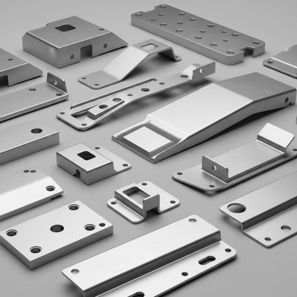
শীট মেটাল ডাই প্রেস অপারেশনের মাধ্যমে উৎপাদিত সাধারণ গাড়ি উপাদানগুলির মধ্যে রয়েছে বডি প্যানেল, কাঠামোগত শক্তিকরণ, সিট ব্র্যাকেট, ইঞ্জিন মাউন্ট, ব্রেক উপাদান এবং অভ্যন্তরীণ ট্রিম টুকরো। প্রত্যেকটির জন্য নির্দিষ্ট উপাদান—হালকা ইস্পাত থেকে উন্নত উচ্চ-শক্তি শ্রেণির ইস্পাত পর্যন্ত—অনুযায়ী ডিজাইন করা টুলিং প্রয়োজন, যা অভিজ্ঞ ডাই ইঞ্জিনিয়ারদেরও চ্যালেঞ্জ করে।
এয়ারোস্পেস অ্যাপ্লিকেশনে নির্ভুলতার প্রয়োজনীয়তা
কল্পনা করুন এমন একটি উপাদান যেখানে কয়েক হাজারাংশ ইঞ্চির টলারেন্স বিচ্যুতি বিমানের নিরাপত্তা ঝুঁকির মধ্যে ফেলতে পারে। এটাই হল এয়ারোস্পেস নির্মাতাদের সম্মুখীন বাস্তবতা, যেখানে নির্ভুলতা সর্বদা উৎপাদন গতির চেয়ে অগ্রাধিকার পায়।
এয়ারোস্পেস ডাই অ্যাপ্লিকেশনগুলি সর্বোচ্চ প্রাধান্য দেয় কঠোর টলারেন্স এবং উপকরণের ট্রেসেবিলিটির ওপর। কম্পোনেন্টগুলি যথাযথ স্পেসিফিকেশন মেনে চলতে হবে, আর ডকুমেন্টেশনে উৎপাদনের প্রতিটি দিককে ট্র্যাক করতে হবে। উৎপাদন শিল্পের গবেষণা লক্ষ্য করেছে যে, এয়ারোস্পেস অ্যাপ্লিকেশনগুলির জন্য "ধাতু স্ট্যাম্পিং পার্টসগুলির চমৎকার শক্তি ও টেকসইতা থাকা আবশ্যিক, যাতে মোট ওজন কমিয়ে ফ্লাইট দক্ষতা বৃদ্ধি করা যায়।"
এয়ারোস্পেসে ব্যবহৃত ফোরজিং ডাইগুলি প্রায়শই বিশেষায়িত সামগ্রী—টাইটানিয়াম, ইনকোনেল এবং এয়ারোস্পেস-গ্রেড অ্যালুমিনিয়াম—এর সাথে কাজ করে, যার জন্য সাধারণ স্টিল স্ট্যাম্পিংয়ের তুলনায় ভিন্ন পদ্ধতির প্রয়োজন হয়। এই সামগ্রীগুলি উত্তপ্ত অপারেশন, বিশেষায়িত লুব্রিক্যান্ট এবং উচ্চমানের টুল স্টিল বা কার্বাইড দিয়ে তৈরি ডাই প্রয়োজন করে, যাতে এদের দ্বারা সৃষ্ট বিশেষ চ্যালেঞ্জগুলি সহ্য করা যায়।
সাধারণ এয়ারোস্পেস স্ট্যাম্পড কম্পোনেন্টগুলি হল:
- অভ্যন্তরীণ কাঠামোগত উপাদান: বিমানের ফ্রেম জুড়ে ব্র্যাকেট, ক্লিপ এবং রিনফোর্সমেন্ট
- বাহ্যিক প্যানেল: যেসব স্কিন সেকশনে নির্ভুল কনটুর এবং সুসঙ্গত পুরুত্ব প্রয়োজন
- ইঞ্জিন উপাদান: তাপ রক্ষাকারী ঢাল, মাউন্টিং হার্ডওয়্যার এবং ডাক্টিং উপাদানসমূহ
- নিয়ন্ত্রণ পৃষ্ঠের অংশসমূহ: হিঞ্জ, অ্যাকচুয়েটর ব্র্যাকেট এবং লিঙ্কেজ উপাদানসমূহ
এয়ারোস্পেস শিল্পে উৎপাদন পরিমাণ সাধারণত গাড়ি শিল্পের চেয়ে কম হয়, কিন্তু গুণগত প্রয়োজনীয়তা প্রতিটি অংশকে উল্লেখযোগ্যভাবে বেশি মূল্যবান করে তোলে। ল্যান্ডিং গিয়ার উপাদান উৎপাদনকারী একটি ফোরজিং ডাই মাঝেমধ্যে মাঝারি গতিতে বছরের পর বছর ধরে কাজ করতে পারে, এবং প্রতিটি ব্যাচ যাচাই করার জন্য ব্যাপক পরীক্ষা প্রোটোকল প্রয়োগ করা হয়।
ইলেকট্রনিক্স শিল্পে সূক্ষ্মীকরণের চ্যালেঞ্জসমূহ
আপনি কতটা ছোট করতে পারেন? ইলেকট্রনিক্স নির্মাতারা এই প্রশ্নটি ধারাবাহিকভাবে তুলে ধরেন, যার ফলে ইঞ্চির পরিবর্তে মিলিমিটারে পরিমাপ করা উপাদান উৎপাদনের জন্য ডাই প্রয়োজন হয়।
ইলেকট্রনিক্স শিল্প এমন উপাদানের চাহিদা রাখে যা LSRPF-এর বিশেষজ্ঞরা "অত্যন্ত উচ্চ নির্ভুলতাসহ ছোট উপাদান—যেমন কানেক্টর, টার্মিনাল, শিল্ড এবং হাউজিং" হিসাবে বর্ণনা করেন। এই স্ট্যাম্পিংগুলির জন্য অন্যান্য শিল্পে অসাধারণ বলে বিবেচিত হওয়া সহনশীলতা প্রয়োজন—কখনও কখনও মাত্র কয়েকটি দশ হাজার ইঞ্চির মধ্যে মাত্রাগুলি ধরে রাখা হয়।
ইলেকট্রনিক্স অ্যাপ্লিকেশনগুলি হল:
- কানেক্টর এবং টার্মিনাল: বিশ্বস্ত বৈদ্যুতিক সংযোগের জন্য নির্ভুল জ্যামিতি প্রয়োজনীয় ক্ষুদ্র যোগাযোগ পিন এবং রিসেপটাকলগুলি
- হিট সিঙ্ক: ফিনযুক্ত গঠন যা প্রসেসর এবং পাওয়ার উপাদানগুলি থেকে তাপীয় শক্তি বিলুপ্ত করে
- RF শিল্ড: আবরণগুলি যা সংবেদনশীল সার্কিটগুলির মধ্যে ইলেকট্রোম্যাগনেটিক হস্তক্ষেপ (EMI) প্রতিরোধ করে
- ব্যাটারি যোগাযোগ বিন্দু: স্প্রিং উপাদানগুলি যা বিশ্বস্ত পাওয়ার সরবরাহের জন্য ধ্রুব চাপ প্রদান করে
- ডিভাইসের আবরণ: স্মার্টফোন, ট্যাবলেট এবং কম্পিউটিং সরঞ্জামের জন্য আবরণ
ইলেকট্রনিক্স উৎপাদনে প্রগ্রেসিভ ডাইগুলি প্রাধান্য বজায় রাখে, যা প্রায়শই উচ্চ গতিতে চালিত হয় পরিমাণগত চাহিদা পূরণের জন্য। ক্ষুদ্র আকারের কারণে টুলিং উপাদানগুলিও অত্যন্ত ক্ষুদ্র হয়ে যায়, যার ফলে প্রয়োজনীয় নির্ভুলতা অর্জনের জন্য বিশেষায়িত উৎপাদন পদ্ধতি এবং উপকরণের প্রয়োজন হয়।
যন্ত্রপাতি এবং ভোক্তা পণ্য প্রয়োগ
আপনার বাড়িতে ঘুরে দেখুন এবং স্ট্যাম্পড ধাতব অংশগুলির সংখ্যা গণনা করুন। রেফ্রিজারেটর প্যানেল, ওয়াশিং মেশিনের ড্রাম, মাইক্রোওয়েভ আবরণ, HVAC উপাদান—স্ট্যাম্পিং আপনার কাছে থাকা প্রায় প্রতিটি যন্ত্রপাতিতেই বিদ্যমান।
যন্ত্রপাতি উৎপাদন টেকসইতা প্রয়োজনীয়তা এবং সৌন্দর্যবোধের দাবিকে ভারসাম্য বজায় রাখে। দৃশ্যমান উপাদানগুলি ছাঁচ থেকে বের হওয়ার পর পেইন্ট করা বা ফিনিশিং করার জন্য উপযুক্ত পৃষ্ঠ সহ আসতে হবে, অন্যদিকে অভ্যন্তরীণ গঠনগুলি শক্তি এবং খরচ-দক্ষতার ওপর গুরুত্ব দেয়। শিল্প সূত্র "মেটাল স্ট্যাম্পিং গৃহ যন্ত্রপাতির উচ্চ টেকসইতা এবং সৌন্দর্যবোধের দাবি পূরণ করে" নিশ্চিত করুন।
সাধারণ যন্ত্রপাতি স্ট্যাম্পিংগুলির মধ্যে রয়েছে:
- বহির্ভাগের আবরণ: রেফ্রিজারেটর দরজা, ওয়াশারের উপরিভাগ, ড্রায়ার প্যানেল
- অভ্যন্তরীণ গঠন: ড্রাম সাপোর্ট, মোটর মাউন্ট, ব্র্যাকেট অ্যাসেম্বলি
- তাপ বিনিময় উপাদান: বাষ্পীভবনকারী ফিন, সংকোচক প্লেট
- হার্ডওয়্যার: হিঞ্জ, ল্যাচ, হ্যান্ডেল ব্র্যাকেট
ভোক্তা পণ্যগুলি এই তালিকাটিকে আরও বাড়িয়ে দেয়—রান্নাঘরের সরঞ্জাম, বাগানের সরঞ্জাম, ক্রীড়া সরঞ্জাম এবং সজ্জা বস্তুগুলি সকলেই দক্ষ উৎপাদনের জন্য স্ট্যাম্পিং-এর উপর নির্ভরশীল। প্রেস ডাই প্রযুক্তির বহুমুখিতা বিভিন্ন পণ্য শ্রেণির মধ্যে ধারাবাহিক মান নিশ্চিত করে।
সাধারণ শিল্প ও বিশেষায়িত প্রয়োগ
প্রধান ভোক্তা শিল্পগুলির বাইরেও, ধাতব প্রেস ডাই অসংখ্য বিশেষায়িত প্রয়োগে ব্যবহৃত হয়:
- নির্মাণ ও ভবন: ছাদের প্যানেল, কাঠামোগত ব্র্যাকেট, জয়েস্ট হ্যাঙ্গার এবং স্থাপত্য ট্রিম টুকরো
- চিকিৎসা যন্ত্রপাতি: শল্যচিকিৎসা যন্ত্রপাতি, রোগ নির্ণয় সরঞ্জামের আবরণ, জৈব-সামঞ্জস্যপূর্ণ উপকরণ প্রয়োজনীয় চিকিৎসা যন্ত্রের উপাদান
- শক্তি ব্যবস্থা: সৌর প্যানেলের ফ্রেম, বাতাসের টারবাইনের উপাদান, বৈদ্যুতিক বিতরণ হার্ডওয়্যার
- সামরিক ও প্রতিরক্ষা: যানবাহনের বর্ম, অস্ত্র ব্যবস্থার উপাদান, যোগাযোগ সরঞ্জামের আবরণ
প্রতিটি অ্যাপ্লিকেশন একটি অনন্য প্রয়োজনীয়তা নিয়ে আসে। চিকিৎসা শিল্পের স্ট্যাম্পিং-এর ক্ষেত্রে উপকরণের ট্রেসেবিলিটি এবং দূষণ প্রতিরোধের প্রয়োজন হয়। সামরিক বিশেষ নির্দেশাবলীতে প্রায়শই কঠোর পরিবেশে চরম স্থায়িত্বের প্রয়োজন হয়। শক্তি সংক্রান্ত অ্যাপ্লিকেশনগুলিতে বহিরঙ্গন ইনস্টলেশনের জন্য ক্ষয় প্রতিরোধের ওপর জোর দেওয়া হতে পারে।
এই বৈচিত্র্যময় শিল্পগুলিকে যা একত্রিত করে, তা হল সঠিকভাবে ডিজাইন করা এবং ভালোভাবে রক্ষণাবেক্ষণ করা টুলিং-এর উপর তাদের নির্ভরশীলতা। স্বয়ংচালিত গাড়ির বডি প্যানেল বা চিকিৎসা যন্ত্রের উপাদান উৎপাদন করা হোক না কেন, ডাই ইঞ্জিনিয়ারিং-এর মৌলিক নীতিগুলি অপরিবর্তিত থাকে—যদিও বিভিন্ন খাতের মধ্যে নির্দিষ্ট প্রয়োজনীয়তাগুলি ব্যাপকভাবে পরিবর্তিত হয়।
শিল্প অ্যাপ্লিকেশনগুলি বোঝা ডাই রক্ষণাবেক্ষণ এবং আয়ু ব্যবস্থাপনাকে কতটা গুরুত্বপূর্ণ করে তা বুঝতে সাহায্য করে। ক্ষয়প্রাপ্ত ডাই কেবল খারাপ পার্টস উৎপাদন করে না—এটি আমরা যেসব খাত নিয়ে আলোচনা করেছি, সেগুলির প্রতিটি ক্ষেত্রেই সম্পূর্ণ উৎপাদন ক্রিয়াকলাপকে ব্যাহত করে।
ডাই রক্ষণাবেক্ষণ এবং আয়ু ব্যবস্থাপনা
আপনার ডাই সরঞ্জামগুলি একটি উল্লেখযোগ্য বিনিয়োগ প্রতিনিধিত্ব করে—কিন্তু সর্বোত্তমভাবে প্রকৌশলীকৃত সরঞ্জামগুলিও যথাযথ যত্ন ছাড়া সামঞ্জস্যপূর্ণ ফলাফল প্রদান করতে পারবে না। আশ্চর্যজনকভাবে, অনেক উৎপাদনকারী প্রতিষ্ঠান উৎপাদন আউটপুটের উপর বেশ মনোযোগ দেয়, কিন্তু তাদের ডাইগুলিকে সর্বোচ্চ দক্ষতায় কাজ করতে সহায়তা করে এমন পদ্ধতিগত রক্ষণাবেক্ষণের প্রতি উদাসীন থাকে। এই উদাসীনতা রক্ষণাবেক্ষণের খরচের চেয়ে অনেক বেশি খরচ সৃষ্টি করে।
ডাই রক্ষণাবেক্ষণ বিশেষজ্ঞদের মতে দ্য ফিনিক্স গ্রুপ , "ডাই শপ ব্যবস্থাপনা পদ্ধতি—যার মধ্যে ডাই রক্ষণাবেক্ষণ ও মেরামত প্রক্রিয়া অন্তর্ভুক্ত—যদি সুস্পষ্টভাবে সংজ্ঞায়িত না হয়, তবে প্রেস লাইনের উৎপাদনক্ষমতা উল্লেখযোগ্যভাবে হ্রাস পাবে এবং খরচ বৃদ্ধি পাবে।" দুর্বল রক্ষণাবেক্ষণ সমস্যার একটি শৃঙ্খল সৃষ্টি করে: উৎপাদনের সময় গুণগত ত্রুটি, বর্জ্য হার বৃদ্ধি, পাঠানোর বিলম্ব এবং ব্যয়বহুল জরুরি মেরামত—যা পূর্বেই প্রতিরোধ করা সম্ভব ছিল।
চলুন এমন প্রতিরোধমূলক অভ্যাস এবং সতর্কতা সংকেতগুলি নিয়ে আলোচনা করি যা তাদের মধ্যে পার্থক্য করে যারা তাদের সরঞ্জাম বিনিয়োগকে সর্বাধিক কার্যকর করে তোলে এবং যারা ধারাবাহিকভাবে ডাই-সম্পর্কিত উৎপাদন সমস্যার বিরুদ্ধে লড়াই করে।
দীর্ঘস্থায়ী ডাই জীবনের জন্য প্রতিরোধমূলক রক্ষণাবেক্ষণ সময়সূচী
ডাই প্রেসিং অপারেশনগুলিকে একটি গাড়ি চালানোর মতো ভাবুন। আপনি যেমন ইঞ্জিন বন্ধ হয়ে যাওয়ার অপেক্ষা করবেন না তারপর তেল পরিবর্তন করবেন—অথচ অনেক উৎপাদনকারী প্রতিষ্ঠান তাদের টুলিংয়ের ক্ষেত্রে মূলত এই একই কাজ করে থাকেন। প্রতিরোধমূলক রক্ষণাবেক্ষণ উৎপাদন ব্যাহত করার আগেই সম্ভাব্য সমস্যাগুলির সমাধান করে।
কার্যকর রক্ষণাবেক্ষণ শুরু হয় পদ্ধতিগত পরিদর্শন প্রোটোকল থেকে। প্রতিবার যখন কোনো ডাই উৎপাদন চক্র থেকে ফিরে আসে, তখন প্রশিক্ষিত কর্মীরা এটিকে সংরক্ষণের আগে এর অবস্থা মূল্যায়ন করবেন। এই পরিদর্শনটি সমস্যাগুলিকে এখনও সামান্য অবস্থায় চিহ্নিত করে—এবং সমাধানগুলি এখনও সাশ্রয়ী মূল্যে পাওয়া যায়।
প্রতিটি উৎপাদন চক্রের পরে এই ক্রমিক পরিদর্শন প্রক্রিয়াটি অনুসরণ করুন:
- সমস্ত ডাই উপাদান গভীরভাবে পরিষ্কার করুন যাতে লুব্রিক্যান্টের অবশিষ্টাংশ, ধাতব কণা এবং অন্যান্য দূষণকারী পদার্থগুলি অপসারণ করা যায় যেগুলি সংরক্ষণকালীন ক্ষয় বা ক্ষয়রোধ ত্বরান্বিত করে।
- কাটিং এজগুলি দৃশ্যমানভাবে এবং স্পর্শ করে পরিদর্শন করুন যাতে চিপ, ফাটল বা অত্যধিক ক্ষয় নির্ণয় করা যায় যা পরবর্তী চক্রে বার্স বা মাত্রাগত সমস্যা সৃষ্টি করতে পারে।
- শীর্ষ ডাই এবং নিম্ন ডাই-এর সাপেক্ষিক অবস্থান পরীক্ষা করুন চাপ প্রয়োগের সময় অসঠিক অবস্থানের ইঙ্গিত দেওয়া সাক্ষ্য চিহ্ন এবং ক্ষয় প্যাটার্ন পরীক্ষা করে।
- ডাই শু-এর অবস্থা যাচাই করুন ফাটল, গাইড পিন বুশিং-এ ক্ষয় এবং মাউন্টিং পৃষ্ঠে যেকোনো ক্ষতি যা অবস্থান নির্ধারণকে প্রভাবিত করতে পারে, তা পরীক্ষা করে।
- স্ট্রিপার প্লেট এবং চাপ প্যাডগুলি পরীক্ষা করুন স্ট্যাম্পিং অপারেশনের সময় উপকরণ নিয়ন্ত্রণকে প্রভাবিত করতে পারে এমন ক্ষয়, আঁচড় বা ক্ষতির জন্য।
- কাজের অর্ডার সিস্টেমে পাওয়া ফলাফলগুলি নথিভুক্ত করুন যাতে সময়মতো মেরামতের জন্য সময়সূচী প্রস্তুতকারী কর্মীরা পরবর্তী উৎপাদন প্রয়োজনীয়তার আগে অগ্রাধিকার নির্ধারণ করতে পারেন।
- সংরক্ষণের জন্য ডাইগুলি স্থানান্তর করার আগে সমস্ত প্রকাশিত পৃষ্ঠে উপযুক্ত মাপের মরিচা-প্রতিরোধী প্রয়োগ করুন।
স্নেহকারী প্রয়োজনীয়তা ডাইয়ের ডিজাইন এবং প্রক্রিয়াকরণের অধীনে থাকা উপকরণের উপর নির্ভর করে। কিছু অপারেশনে সর্বনিম্ন স্নেহকারী প্রয়োজন হয়, অন্যদিকে গভীর টানা (ডিপ ড্রয়িং) অ্যাপ্লিকেশনগুলি—বিশেষ করে—গ্যালিং প্রতিরোধ করতে এবং ফর্মিং বল কমাতে স্থির স্নেহকারী প্রয়োগের প্রয়োজন হয়। প্রতিটি ডাই সেটের কার্যক্রমের প্রয়োজনীয়তা অনুযায়ী নির্দিষ্ট স্নেহকারী প্রোটোকল প্রতিষ্ঠা করুন।
কাটিং এজগুলির ধার করার সময়সূচী অনুমানের উপর নির্ভর করা উচিত নয়। যেমন গ্রোম্যাক্স প্রিসিশন সুপারিশ করেছেন, "পাঞ্চগুলি কখন ধার করা প্রয়োজন বা ইনসার্টগুলি প্রতিস্থাপন করা প্রয়োজন তা অনুমান না করে, কয়েল গণনা, হিট লগ এবং ভবিষ্যদ্বাণীমূলক মডেলিং ব্যবহার করে একটি প্রতিরোধমূলক রক্ষণাবেক্ষণ সময়সূচী তৈরি করুন যা প্রতিক্রিয়াশীল নয়, বরং পূর্বাভাসী হবে।" ধার করার মধ্যবর্তী স্ট্রোক গণনা ট্র্যাক করুন এবং যথার্থ ক্ষয় প্যাটার্নের ভিত্তিতে থ্রেশহোল্ড নির্ধারণ করুন, যার পরিবর্তে যাদৃচ্ছিক ব্যবধান ব্যবহার করা হয়।
সঠিক সংরক্ষণ উৎপাদন চক্রের মধ্যবর্তী সময়ে আপনার বিনিয়োগকে রক্ষা করে। সম্ভব হলে ডাইগুলি জলবায়ু-নিয়ন্ত্রিত পরিবেশে সংরক্ষণ করুন, যাতে করে ক্ষয় ঘটানোর জন্য আর্দ্রতার উৎস থেকে তাদের দূরে রাখা যায়। ডাই শুজগুলিকে যথাযথভাবে সমর্থন করুন যাতে বিকৃতি রোধ করা যায়, এবং স্পষ্ট চিহ্নিতকরণ বজায় রাখুন যাতে অপারেটররা প্রয়োজন হলে দ্রুত টুলিং খুঁজে পেতে পারেন।
ডাই ক্ষয়ের লক্ষণগুলি চিহ্নিত করা
উৎকৃষ্ট প্রতিরোধমূলক রক্ষণাবেক্ষণ সত্ত্বেও, ডাই উপাদানগুলি শেষ পর্যন্ত ক্ষয় হয়। প্রাথমিক সতর্কতা সংকেতগুলি চিহ্নিত করা আপনাকে উৎপাদন ব্যাহত হওয়ার পর জরুরি মেরামতের পরিবর্তে পরিকল্পিত বন্ধের সময়ে মেরামতের সুযোগ করে দেয়।
আপনার ডাই সরঞ্জামের মনোযোগ প্রয়োজন এমন নিম্নলিখিত সূচকগুলির দিকে লক্ষ্য রাখুন:
- বার গঠন: যখন সঠিকভাবে রক্ষণাবেক্ষণ করা কাটিং এজগুলি স্ট্যাম্পড অংশে বার্স উৎপাদন করতে শুরু করে, তখন সম্ভবত ক্ষয়ের কারণে ক্লিয়ারেন্স পরিবর্তিত হয়েছে। ছোট বার্স প্রাথমিক পর্যায়ের ক্ষয় নির্দেশ করে; ভারী বার্স নির্দেশ করে যে ডাইটি এর রক্ষণাবেক্ষণের সময়সীমা অতিক্রম করে অনেকদিন ধরে কাজ করছে।
- মাত্রিক ড্রিফট: ধীরে ধীরে সহনশীলতা ছাড়িয়ে যাওয়া অংশগুলিঘরগুলি আরও বড় হয়ে উঠছে, বাঁকগুলি কোণ পরিবর্তন করে, বা বৈশিষ্ট্যগুলি অবস্থান পরিবর্তন করেপ্রায়শই কাটিয়া উপাদান, গাইড পিন বা ডাই জুতো বুশিংগুলিতে সংকেত পরা।
- টনালাইজিংয়ের প্রয়োজনীয়তা বৃদ্ধিঃ আধুনিক সার্ভো প্রেস এবং পুনর্নির্মাণ লোড মনিটরিং সিস্টেমগুলি শক্তি স্বাক্ষর পরিবর্তন সনাক্ত করতে পারে। শিল্প বিশেষজ্ঞরা উল্লেখ করেন যে "টোন্যাজের ধীর বৃদ্ধি প্রায়ই অলস টুলিং বা ভুল সমন্বয়ের ইঙ্গিত দেয় যে এটি দীর্ঘ সময় পর্যন্ত মেরামত করার সময় আগে এটি অত্যন্ত গুরুত্বপূর্ণ সূত্র যা tolerances খুব দূরে drifted। "
- পৃষ্ঠের সমাপ্তি অবনতিঃ গঠিত অংশের উপর স্ক্র্যাচ, জ্বালা চিহ্ন, বা রুক্ষ পৃষ্ঠগুলি গঠিত পৃষ্ঠের পরিধান বা অপর্যাপ্ত তৈলাক্তকরণের ইঙ্গিত দেয়।
- অসঙ্গত অংশের মান: যখন একই উৎপাদন রান থেকে অংশগুলি উল্লেখযোগ্য বৈচিত্র দেখায়, সমন্বয় সমস্যা বা পরিধানযুক্ত অবস্থান সনাক্তকারী বৈশিষ্ট্যগুলি দোষী হতে পারে।
উন্নত মনিটরিং টুলগুলি সমস্যা শনাক্তকরণকে ত্বরান্বিত করে। শিল্প বিশেষজ্ঞদের মতে, কৃত্রিম বুদ্ধিমত্তা-চালিত পরিসংখ্যানিক প্রক্রিয়া নিয়ন্ত্রণ (SPC) সিস্টেমগুলি "হাতে করা পরীক্ষার চেয়ে আগেই সূক্ষ্ম প্রবণতা—যেমন বর্ধিত বার্স (burrs) বা মাত্রাগত অপসরণ (dimensional creep)—শনাক্ত করে"। লাইনের মধ্যে অবস্থিত ভিশন পরীক্ষা সিস্টেমগুলি বাস্তব সময়ে মাইক্রো-স্তরের মাত্রাগত পরিবর্তনগুলি ধরা দেয়, যা উৎপাদন চলাকালীন সমস্যাগুলি শনাক্ত করে—অন্তিম লাইনে প্রত্যাখ্যানের অপেক্ষা না করে।
পুনঃগ্রাইন্ডিং বনাম প্রতিস্থাপনের সিদ্ধান্ত
যখন কাটিং এজগুলি ধুলো হয় বা ফর্মিং পৃষ্ঠগুলি ক্ষয়প্রাপ্ত হয়, তখন আপনি একটি মৌলিক প্রশ্নের মুখোমুখি হন: বিদ্যমান উপাদানগুলি পুনরায় গ্রাইন্ড করবেন নাকি সম্পূর্ণরূপে প্রতিস্থাপন করবেন? এই উত্তরটি একাধিক বিষয়ের উপর নির্ভর করে।
যেসব ক্ষেত্রে পুনঃগ্রাইন্ডিং অর্থনৈতিকভাবে যুক্তিযুক্ত:
- ক্ষয় কেবলমাত্র পৃষ্ঠের স্তরগুলিতে সীমাবদ্ধ, যা যথেষ্ট উপাদান পুরুত্ব বজায় রেখে অপসারণ করা যায়
- উপাদানগুলি তাদের জ্যামিতিক নির্ভুলতা বজায় রাখে এবং নির্দিষ্ট মানে পুনরুদ্ধার করা যায়
- পুনরায় গ্রাইন্ডিংয়ের খরচ এবং সেটআপ সময় প্রতিস্থাপন খরচের তুলনায় উল্লেখযোগ্যভাবে কম থাকে
- পুনরায় গ্রাইন্ডিংয়ের পরেও ডাইয়ের যথেষ্ট জীবনকাল অবশিষ্ট থাকে, যা এই বিনিয়োগকে যৌক্তিক করে
প্রতিস্থাপন প্রয়োজন হয় যখন:
- বারবার পুনর্গ্রাইন্ডিংয়ের ফলে উপলব্ধ উপাদান শেষ হয়ে গেছে, যার ফলে উপাদানগুলি আরও ব্যবহারের জন্য অত্যধিক পাতলা হয়ে গেছে
- ক্ষতি পৃষ্ঠের ক্ষয়ের চেয়ে বেশি এগিয়ে গেছে—যেমন ফাটল, চিপস বা বিকৃতি, যা পুনর্গ্রাইন্ডিং দ্বারা সমাধান করা সম্ভব নয়
- পূর্ববর্তী পুনর্গ্রাইন্ডিংগুলির ফলে সঞ্চিত মাত্রাগত পরিবর্তনগুলি ডাইটিকে গ্রহণযোগ্য সহনশীলতার সীমা অতিক্রম করে দিয়েছে
- প্রতিস্থাপনকৃত উপাদানগুলির খরচ এবং লিড টাইম পুনর্গ্রাইন্ডিংয়ের খরচের সমতুল্য
ডাইয়ের সামগ্রিক আয়ুষ্কালকে প্রভাবিত করে এমন বিভিন্ন বিষয়ের মধ্যে রয়েছে প্রক্রিয়াজাতকৃত উপাদান (ক্ষয়কারী উপাদানগুলি ক্ষয়কে ত্বরান্বিত করে), উৎপাদন পরিমাণ, প্রেসের সঠিক সাইজিং ও অবস্থা, এবং অপারেটরদের কাজের পদ্ধতি। একটি ভালভাবে রক্ষণাবেক্ষিত প্রেসে পরিষ্কার অ্যালুমিনিয়াম প্রক্রিয়া করে চলা ডাইয়ের আয়ু একই টুলিংয়ের চেয়ে দশ গুণ বেশি হতে পারে যা সমস্যাযুক্ত সাইজিং বিশিষ্ট সরঞ্জামে ক্ষয়কারী স্টেইনলেস স্টিল প্রক্রিয়া করছে।
প্রতিটি ডাই সেটের জন্য বিস্তারিত রেকর্ড রাখা ডাইগুলির পুনঃগ্রাইন্ডিং বা প্রতিস্থাপনের সময় ভবিষ্যদ্বাণী করতে সাহায্য করে, যার ফলে আপনি ব্যর্থতার প্রতিক্রিয়ায় না গিয়ে নির্ধারিত ডাউনটাইমের সময় রক্ষণাবেক্ষণের পরিকল্পনা করতে পারেন। এই প্রতিরোধমূলক পদ্ধতি—যা পদ্ধতিগত পরিদর্শন, তথ্য-ভিত্তিক সময়সূচী প্রণয়ন এবং সমস্যার প্রাথমিক সনাক্তকরণকে একত্রিত করে—ডাই রক্ষণাবেক্ষণকে খরচ কেন্দ্র থেকে প্রতিযোগিতামূলক সুবিধায় রূপান্তরিত করে।
রক্ষণাবেক্ষণের প্রয়োজনীয়তা বোঝা আপনাকে ডাইয়ের গুণগত মান কীভাবে সরাসরি আপনার উৎপাদন ফলাফলকে প্রভাবিত করে তা মূল্যায়ন করতে সক্ষম করে—এই সংযোগটি শুধুমাত্র সরল অংশ উৎপাদনের বাইরে গিয়ে মোট মালিকানা খরচ (Total Cost of Ownership) বিবেচনার মধ্যে প্রসারিত হয়।
ডাই পারফরম্যান্স এবং উৎপাদন গুণগত মান
আপনি উচ্চমানের টুলিংয়ে বিনিয়োগ করেছেন এবং দৃঢ় রক্ষণাবেক্ষণ পদ্ধতি প্রতিষ্ঠা করেছেন—কিন্তু এই সিদ্ধান্তগুলো আসলে কীভাবে উৎপাদন ফলাফলে রূপান্তরিত হয়? ডাইয়ের মান এবং উৎপাদন ফলাফলের মধ্যে সম্পর্কটি সর্বদা স্পষ্ট হয় না, তবুও এটি অংশগুলোর সামঞ্জস্যতা থেকে শুরু করে আপনার চূড়ান্ত লাভ-ক্ষতির পর্যন্ত সবকিছুকে প্রভাবিত করে। এই সম্পর্কটি বুঝতে পারলে আপনি টুলিংয়ে বিনিয়োগ সংক্রান্ত সঠিক সিদ্ধান্ত গ্রহণ করতে পারবেন, যা বছরের পর বছর ধরে লাভজনক হবে।
আপনার প্রেস ডাই সেটটিকে আপনার সমগ্র উৎপাদন ব্যবস্থার ভিত্তি হিসেবে ভাবুন। যেমন একটি অস্থির ভিত্তির উপর নির্মিত ভবনের সময়ের সাথে সাথে ফাটল ও গঠনগত সমস্যা দেখা দেয়, ঠিক তেমনি নিম্নমানের টুলিংয়ের উপর ভিত্তি করে গঠিত উৎপাদন অবশ্যই গুণগত সমস্যা, দক্ষতা হ্রাস এবং সময়ের সাথে সাথে প্রবৃদ্ধ হয়ে যাওয়া লুকানো খরচ তৈরি করে।
ডাইয়ের মান কীভাবে উৎপাদন দক্ষতাকে প্রভাবিত করে
আপনি কখনও একটি ভালভাবে ডিজাইন করা প্রোগ্রেসিভ ডাই পূর্ণ গতিতে চলতে দেখেছেন? অংশগুলি ধারাবাহিকভাবে, প্রতিটি স্ট্রোকের পর প্রতিটি স্ট্রোকে নির্গত হয়, যাতে অপারেটরের হস্তক্ষেপ ন্যূনতম থাকে। এটাই উচ্চমানের টুলিং প্রদান করে—কিন্তু এর সুবিধাগুলি চমকপ্রদ সাইকেল সময়ের চেয়ে অনেক বেশি বিস্তৃত।
এলএমসি ইন্ডাস্ট্রিজের উৎপাদন দক্ষতা গবেষণা অনুসারে, প্রোগ্রেসিভ ডাই স্ট্যাম্পিং "বহুসংখ্যক পৃথক পৃথক অপারেশনের প্রয়োজনীয়তা বাতিল করে উৎপাদন সময় ও খরচ উল্লেখযোগ্যভাবে কমিয়ে দেয়।" এই দক্ষতা সুবিধাটি সরাসরি টুলিংয়ের গুণগত মান থেকে উদ্ভূত হয়। যখন প্রেস অপারেশনের জন্য ডাই সেটগুলি সঠিকভাবে প্রকৌশলীকৃত হয়, তখন প্রতিটি স্ট্রোকে বর্জ্য না হয়ে ব্যবহারযোগ্য অংশ উৎপন্ন হয়।
গুণগত মানের টুলিং কয়েকটি যান্ত্রিক পদ্ধতির মাধ্যমে দক্ষতাকে প্রভাবিত করে:
- ডাউনটাইম হ্রাসঃ নির্ভুলভাবে নির্মিত ধাতব স্ট্যাম্পিং ডাই সেটগুলি দীর্ঘ সময় ধরে সঠিক সাইজিং বজায় রাখে, ফলে সামঞ্জস্য বা মেরামতের জন্য উৎপাদন বন্ধ করার প্রয়োজন কম হয়
- উচ্চ প্রথম-পাস আউটপুট: অংশগুলি প্রথম প্রয়াসেই নির্দিষ্টকৃত মান পূরণ করে, যার ফলে সময় ও সম্পদ ব্যয় করে পুনরায় কাজ করার প্রয়োজন হয় না
- দ্রুত চক্র সময়: ভালভাবে নকশা করা ডাইগুলি চাপ প্রয়োগকারী মেশিনগুলিকে গুণগত ক্ষতি ছাড়াই অপটিমাল গতিতে চালানোর অনুমতি দেয়
- সামঞ্জস্যপূর্ণ আউটপুট: মাত্রিক স্থিতিশীলতার অর্থ হলো উৎপাদন শুরুর সময় তৈরি করা অংশগুলি ঘণ্টা বা দিন পরে উৎপাদিত অংশগুলির সাথে মিলে যায়
উপযুক্তভাবে নকশা করা এবং রক্ষণাবেক্ষণ করা ডাইগুলির মাধ্যমে যে সহনশীলতা (টলারেন্স) অর্জন করা যায়, তা প্রায়শই নিম্নমানের টুলিং-এর সাথে কাজ করে অভ্যস্ত উৎপাদকদের বিস্মিত করে। শিল্প বিশেষজ্ঞরা নিশ্চিত করেছেন যে, গুণগত প্রগ্রেসিভ ডাইগুলি "অত্যন্ত নির্দিষ্ট প্রয়োজনীয়তা মেটানোর ক্ষেত্রে সামঞ্জস্যপূর্ণভাবে উপযুক্ত উপাদানগুলি" তৈরি করে, যা বিকল্প উৎপাদন পদ্ধতির তুলনায় কঠোরতর সহনশীলতা এবং উচ্চতর অংশের নির্ভুলতা প্রদর্শন করে।
এই নির্ভুলতা সরাসরি পরবর্তী অ্যাসেম্বলি অপারেশনগুলিকে প্রভাবিত করে। যখন স্ট্যাম্পড উপাদানগুলি নির্দিষ্ট সীমার মধ্যে থাকে এবং অ্যাসেম্বলি স্টেশনগুলিতে পৌঁছায়, তখন সেগুলি প্রথমবারেই সঠিকভাবে ফিট হয়। অপারেটররা অংশ নির্বাচন, জোর করে ফিট করা বা অ্যাসেম্বলিগুলি প্রত্যাখ্যান করায় সময় নষ্ট করেন না। হাজার হাজার অ্যাসেম্বলি চক্রের মাধ্যমে এই সংযুক্ত প্রভাবটি উল্লেখযোগ্য উৎপাদনশীলতা বৃদ্ধির দিকে পরিচালিত করে।
ডাইয়ের নির্ভুলতা এবং পার্টের সামঞ্জস্যতার মধ্যে সম্পর্ক
কল্পনা করুন, কয়েক মাস ধরে এক মিলিয়ন পার্ট উৎপাদন করা হচ্ছে। এক মিলিয়ন তম পার্টটি কি প্রথম পার্টটির সঙ্গে মিলে যাবে? গুণগত টুলিং এবং উপযুক্ত রক্ষণাবেক্ষণের সাহায্যে এর উত্তর হওয়া উচিত 'হ্যাঁ'।
পার্টের সামঞ্জস্যতা নির্ভর করে ডাইয়ের কয়েকটি পরস্পর-সংযুক্ত বৈশিষ্ট্যের উপর:
- মাত্রাগত স্থিতিশীলতা: ডাই শুজ, গাইড সিস্টেম এবং উপাদান মাউন্টিং বহু সময় ধরে চলমান উৎপাদন প্রক্রিয়ায় তাদের পারস্পরিক সম্পর্ক বজায় রাখতে হবে
- অপচয় প্রতিরোধ: কাটিং এজ এবং ফর্মিং পৃষ্ঠগুলি অবশ্যই এমন ক্ষয়ক্ষতির বিরুদ্ধে প্রতিরোধ করবে যা ধীরে ধীরে পার্টের মাত্রা পরিবর্তন করে দেবে
- উত্তপ্ত ব্যবস্থাপনা: উৎপাদন গতিতে চলমান ডাইগুলি তাপ উৎপন্ন করে, যা যদি উপযুক্তভাবে নিয়ন্ত্রণ না করা হয় তবে প্রসারণ এবং মাত্রাগত পরিবর্তন ঘটাতে পারে
- উপাদান নিয়ন্ত্রণ: স্ট্রিপার, পাইলট এবং ফিড সিস্টেমগুলি প্রতিটি স্ট্রোকে উপাদানকে একইভাবে অবস্থান করতে হবে
যখন এই উপাদানগুলো একসাথে কাজ করে, তখন উৎপাদকরা গুণগতভাবে সংবেদনশীল অ্যাপ্লিকেশনগুলির জন্য প্রয়োজনীয় উৎপাদন সামঞ্জস্যতা অর্জন করেন। উদাহরণস্বরূপ, অটোমোটিভ সরবরাহকারীদের তাদের প্রক্রিয়াগুলি সময়ের সাথে সাথে ক্ষমতা বজায় রাখছে—এটি প্রমাণ করার জন্য পরিসংখ্যানগত প্রক্রিয়া নিয়ন্ত্রণ (SPC) ডেটা উপস্থাপন করতে হয়। এই ক্ষমতা সরাসরি টুলিংয়ের নির্ভুলতা থেকে উদ্ভূত হয়।
মোট মালিকানা খরচের বিবেচনা
এখানেই অনেক ক্রয় সিদ্ধান্ত ভুল হয়: শুধুমাত্র প্রাথমিক ডাইয়ের খরচের ওপর ফোকাস করা হয়, কিন্তু প্রকৃত উৎপাদন অর্থনীতি নির্ধারণ করে এমন অন্যান্য গুরুত্বপূর্ণ বিষয়গুলোকে উপেক্ষা করা হয়।
ম্যানর টুল কর্তৃক সম্পাদিত মোট খরচ বিশ্লেষণ অনুযায়ী, "উচ্চ-গুণগত মেটাল স্ট্যাম্পড পার্টস বৃহৎ পরিমাণে উৎপাদন করা শুরু হয় টুলিং ও ডাই থেকে। এগুলো সমগ্র প্রক্রিয়ায় সবচেয়ে গুরুত্বপূর্ণ উপাদান।" তাদের গবেষণা দেখায় যে, উচ্চ-গুণগত ডাইগুলো "অংশগুলোর গুণগত মান বজায় রাখতে কোনও রক্ষণাবেক্ষণ ছাড়াই ১,০০০,০০০+ বার আঘাত করতে পারে", অন্যদিকে নিম্ন-গুণগত বিকল্পগুলো "অনেক দ্রুত ক্ষয়প্রাপ্ত হয় এবং তাতে ত্রুটি ও ত্রুটিপূর্ণ অংশ আগেই উৎপন্ন হয়।"
প্রকৃত খরচের চিত্রটি শুধুমাত্র প্রাথমিক ক্রয়মূল্যের চেয়ে অনেক বেশি কিছু অন্তর্ভুক্ত করে:
| গুণগত মানের ফ্যাক্টর | উৎপাদন ফলাফলের উপর প্রভাব | খরচ সংক্রান্ত প্রভাব |
|---|---|---|
| টুল স্টিলের গ্রেড এবং কঠোরতা | ক্ষয় হার এবং রক্ষণাবেক্ষণের সময়সীমা নির্ধারণ করে | উচ্চতর প্রাথমিক খরচ দীর্ঘমেয়াদী সেবা জীবন দ্বারা ক্ষতিপূরণ করা হয় |
| ডিজাইনের নির্ভুলতা এবং অনুকরণ | প্রথম পাস অনুমোদনের হার এবং পার্টের গুণগত মানকে প্রভাবিত করে | খরচ, পুনরায় কাজ করা এবং উন্নয়নের পুনরাবৃত্তিগুলি হ্রাস করা হয় |
| কম্পোনেন্ট সাইটিং সিস্টেম | উৎপাদনের মধ্যে মাত্রিক সামঞ্জস্য নিয়ন্ত্রণ করে | নিম্ন প্রত্যাখ্যান হার এবং সংযোজন সমস্যা |
| পৃষ্ঠ ট্রিটমেন্ট এবং কোটিং | কাটিং এজ এবং ফর্মিং সারফেসের আয়ু বৃদ্ধি করে | ধার দেওয়ার ফ্রিক uয়েন্সি এবং প্রতিস্থাপন খরচ হ্রাস |
| রক্ষণাবেক্ষণ অ্যাক্সেসিবিলিটি | দৈনিক পরিষেবার জন্য প্রয়োজনীয় সময় নির্ধারণ করে | শ্রম খরচ হ্রাস এবং উৎপাদনে ফিরে আসার গতি বৃদ্ধি |
খরচ গণনায় স্ক্র্যাপ হারগুলি বিশেষ মনোযোগের যোগ্য। ফ্রিগেট-এর গবেষণা জোর দেয় যে, "প্রতিবার একটি ত্রুটিপূর্ণ অংশ তৈরি হলে, তা ফেলে দিতে হয় এবং তার পরিবর্তে নতুন উপকরণ ব্যবহার করতে হয়। এর মানে হলো কাঁচামাল, শ্রম এবং শক্তির উপর আরও বেশি অর্থ ব্যয় করা হয়।" উচ্চ মানের প্রেস ডাই সেটগুলি ত্রুটির উৎসগুলি দূর করে এই অপচয় কমিয়ে দেয়।
এই পরিস্থিতিটি বিবেচনা করুন: একটি কম খরচের ডাই প্রাথমিক ক্রয়ে $১৫,০০০ সাশ্রয় করে, কিন্তু এটি ২% বেশি স্ক্র্যাপ হার তৈরি করে এবং প্রতি ২৫০,০০০ স্ট্রোক পর রক্ষণাবেক্ষণের প্রয়োজন হয়—যখন অন্যটির ক্ষেত্রে এটি প্রতি এক মিলিয়ন স্ট্রোক পর হয়। কয়েক বছর ধরে চলমান উৎপাদন প্রোগ্রামে যেখানে মিলিয়ন গুলি পার্টস তৈরি করা হয়, সেখানে এই পার্থক্যগুলি সহজেই প্রাথমিক সাশ্রয়ের দশগুণ খরচ ঘটায়—উৎপাদন বাধাগুলি, গুণগত ত্রুটির পালানো (quality escapes) এবং নিম্নমানের টুলিং-এর সাথে সাধারণত যে গ্রাহক সম্পর্কের ক্ষতি হয়, তা হিসাব করা হয়নি।
মোট মালিকানা খরচ (Total Cost of Ownership) দৃষ্টিভঙ্গি আপনার ডাই বিনিয়োগ মূল্যায়নের পদ্ধতিকে রূপান্তরিত করে। এখন প্রশ্নটি হয়ে ওঠে না "কোন ডাইটি কম খরচের?", বরং হয়ে ওঠে "কোন ডাইটি তার সম্পূর্ণ উৎপাদন জীবনকাল ধরে প্রতিটি গুণগত পার্টসের জন্য সবচেয়ে কম খরচ প্রদান করে?" এই চিন্তার পরিবর্তনটি এমন ক্রয় সিদ্ধান্তের দিকে নিয়ে যায় যা আপনার প্রতিযোগিতামূলক অবস্থানকে শক্তিশালী করে, না যেটি তা দুর্বল করে।
ডাইয়ের মান কীভাবে উৎপাদন অর্থনীতির সাথে যুক্ত তা বোঝা আপনাকে সম্ভাব্য টুলিং সরবরাহকারীদের মূল্যায়ন করতে সক্ষম করে, যাতে আপনি যা প্রকৃতপক্ষে গুরুত্বপূর্ণ তা স্পষ্টভাবে বুঝতে পারেন—এটি একটি গুরুত্বপূর্ণ দক্ষতা, যা আমরা পরবর্তীতে সরবরাহকারী নির্বাচনের মাপদণ্ড এবং প্রমাণীকরণের প্রয়োজনীয়তা নিয়ে আলোচনা করার সময় আলোচনা করব।
আপনার উৎপাদন প্রয়োজনের জন্য সঠিক ডাই সমাধান নির্বাচন করা
আপনি ডাইয়ের প্রকার, উপকরণ এবং প্রকৌশলী নীতিগুলি বুঝেন—কিন্তু কীভাবে আপনি এমন একজন সরবরাহকারীকে খুঁজে পাবেন যিনি আপনার এই জ্ঞানকে প্রকৃতপক্ষে কার্যকরী টুলিং-এ রূপান্তরিত করতে সক্ষম? আপনার সমগ্র টুলিং প্রোগ্রামের মধ্যে সঠিক ডাই পার্টনার নির্বাচন করা সম্ভবত সবচেয়ে গুরুত্বপূর্ণ সিদ্ধান্ত। একজন দক্ষ সরবরাহকারী আপনার স্পেসিফিকেশনগুলিকে এমন প্রিসিশন টুলিং-এ রূপান্তরিত করেন, যা বছরের পর বছর ধরে নির্ভরযোগ্যভাবে চলে। ভুল পছন্দ করলে আপনি মাথাব্যথা, বিলম্ব এবং অংশগুলির গুণগত মানের অবনতির সম্মুখীন হন, যা আপনার সমগ্র অপারেশনে প্রভাব ফেলে।
আপনি যদি ভারী ফর্মিং অপারেশনের জন্য একটি হাইড্রোলিক প্রেস ডাই সেট বা শীট মেটাল ফ্যাব্রিকেশনের জন্য বেন্ডিং ডাই সরবরাহ করছেন, তাহলে মূল্যায়নের মাপদণ্ডগুলি একই থাকে। চলুন দেখি কীভাবে অসাধারণ ডাই সরবরাহকারীদের সেইসব সরবরাহকারীদের থেকে পৃথক করা যায় যারা শুধুমাত্র নিজেদের দক্ষতার দাবি করেন।
ডাই সরবরাহকারীদের মূল্যায়নের প্রধান মাপদণ্ড
কল্পনা করুন, আপনি একটি গুরুত্বপূর্ণ উৎপাদন প্রোগ্রাম এমন একজন সরবরাহকারীর কাছে দিয়েছেন যিনি ভালো কথা বলেন, কিন্তু প্রতিশ্রুতি রাখতে পারেন না। আপনি মাস ধরে বিকাশ সময় হারিয়েছেন, ব্যবহারযোগ্য না হওয়া টুলিং-এ অর্থ ব্যয় করেছেন এবং এখন আপনার গ্রাহকদের কাছে বিলম্বের ব্যাখ্যা দিতে বাধ্য হচ্ছেন। এই পরিস্থিতি যথেষ্ট ঘটে—কিন্তু এটি পদ্ধতিগত সরবরাহকারী মূল্যায়নের মাধ্যমে এড়ানো যায়।
উৎপাদন বিশেষজ্ঞদের মতে ডিউইনটেক , "একজন সরবরাহকারীর প্রকৌশলী দক্ষতা মূল্যায়ন করা হলে তাঁর প্রযুক্তিগত দক্ষতা, ডিজাইনের নমনীয়তা, সমস্যা সমাধানের ক্ষমতা এবং অতীত কার্যকারিতা বিবেচনা করা হয়।" এই বহুমাত্রিক পদ্ধতি আপনার নির্দিষ্ট প্রয়োজনীয়তা পূরণ করতে সক্ষম কিনা তা নির্ধারণ করে।
আপনার হাইড্রোলিক প্রেস টুলিং বা স্ট্যাম্পিং ডাই সরবরাহকারী নির্বাচন করার সময় এই অত্যাবশ্যকীয় মূল্যায়ন মাপদণ্ডগুলি বিবেচনা করুন:
- প্রযুক্তিগত জ্ঞানের গভীরতা: ইঞ্জিনিয়ারিং দলটি কি আপনার উপকরণগুলির সাথে সম্পর্কিত ধাতুবিদ্যা, তাপ চিকিৎসা প্রক্রিয়া এবং যন্ত্রকরণ পদ্ধতিগুলি বুঝতে পারে? আপনার প্রয়োগের বিষয়ে নির্দিষ্ট প্রশ্ন করুন এবং তাদের উত্তরগুলির বৈশিষ্ট্য ও জটিলতা মূল্যায়ন করুন।
- ডিজাইন ও প্রোটোটাইপিং সেবা: তারা কি সম্পূর্ণ উৎপাদন টুলিং-এ যাওয়ার আগে আপনার ড্রয়িংগুলিকে কার্যকরী প্রোটোটাইপে রূপান্তরিত করতে পারে? প্রোটোটাইপিং সেবা প্রদানকারী সরবরাহকারীরা তাদের ইঞ্জিনিয়ারিং দক্ষতার প্রতি আত্মবিশ্বাস প্রদর্শন করে।
- সিমুলেশন ও যাচাইকরণ প্রক্রিয়া: তারা কি ভৌত টুলিং তৈরি না হওয়া পর্যন্ত উপকরণের আচরণ ভবিষ্যদ্বাণী করতে এবং ত্রুটিগুলি চিহ্নিত করতে CAE বিশ্লেষণ ও ফাইনাইট এলিমেন্ট পদ্ধতি ব্যবহার করে? এই দক্ষতা উন্নয়ন পুনরাবৃত্তির সংখ্যা উল্লেখযোগ্যভাবে কমিয়ে দেয়।
- অনুরূপ প্রকল্পে তাদের রেকর্ড: তারা কি আপনার মতো অ্যাপ্লিকেশনের জন্য টুলিং সফলভাবে ডেলিভারি করেছেন? প্রাসঙ্গিক অভিজ্ঞতা প্রদর্শনকারী কেস স্টাডিজ বা গ্রাহক রেফারেন্স অনুরোধ করুন।
- সমস্যা সমাধানের উদ্ভাবন: তারা কি আপনার ডিজাইনগুলিতে উন্নতি সাধনের পরামর্শ দিতে পারেন, বিকল্প উপকরণ প্রস্তাব করতে পারেন অথবা কার্যকারিতা উন্নত করতে বা খরচ কমাতে উৎপাদন পদ্ধতির সুপারিশ করতে পারেন?
- উৎপাদন পরিমাণের ক্ষমতা: আপনার যদি প্রোটোটাইপের পরিমাণ বা বার্ষিক লক্ষাধিক পার্টস প্রয়োজন হয়, তবে গুণগত মান কমানো ছাড়াই আপনার প্রয়োজনীয়তা পূরণে সরবরাহকারীর স্কেল করার ক্ষমতা যাচাই করুন।
আজকের সংক্ষিপ্ত উন্নয়ন চক্রে প্রোটোটাইপিংয়ের গতি বিশেষ মনোযোগের যোগ্য। TiRapid-এর গবেষণা নিশ্চিত করে যে, "3D প্রিন্টিং-এর মতো দ্রুত প্রোটোটাইপিং পদ্ধতি ব্যবহার করে টুলিং-এর পরে সংশোধনের তুলনায় পুনরায় ডিজাইনের খরচ ৬০% পর্যন্ত কমানো যায়।" দ্রুত প্রোটোটাইপিং প্রদানকারী সরবরাহকারীরা—যাদের মধ্যে কিছু মাত্র পাঁচ দিনের মধ্যে কার্যকরী প্রোটোটাইপ তৈরি করতে সক্ষম—ডিজাইন যাচাইকরণকে ত্বরান্বিত করে এবং বাজারে আসার সময়কে আরও দ্রুত করে তোলে।
প্রথম পাস অনুমোদন হারের গুরুত্বকে অতিমাত্রায় চিহ্নিত করা যায় না। যখন ডাইগুলি প্রথম উৎপাদন চক্রেই গুণগত পার্টস তৈরি করে, তখন আপনি ব্যয়বহুল পুনরাবৃত্তি, সময়সূচির বিলম্ব এবং উন্নয়নের সময় যেসব সমস্যা সমাধান করা উচিত ছিল তাদের পিছনে ছুটে যাওয়ার হতাশা এড়াতে পারেন। উন্নত CAE সিমুলেশন সম্ভাব্য সমস্যাগুলিকে ভার্চুয়ালি চিহ্নিত করে এবং সমাধান করে এই উচ্চ প্রথম পাস হারগুলিকে সরাসরি সক্ষম করে।
এরকম উৎপাদকদের মতো Shaoyi এই ক্ষমতাগুলি ব্যবহারিকভাবে কীভাবে কাজ করে তা দেখানোর জন্য উদাহরণ দেওয়া হয়েছে। তাদের প্রকৌশলী দল মাত্র ৫ দিনের মধ্যে দ্রুত প্রোটোটাইপিং সরবরাহ করে এবং একইসাথে ৯৩% প্রথম পাস অনুমোদন হার বজায় রাখে—এই মেট্রিকগুলি বাজারজাতকরণের দাবির চেয়ে বরং প্রকৃত প্রকৌশলী দক্ষতার প্রতিফলন ঘটায়। গতি এবং নির্ভুলতার এই সংমিশ্রণ আপনার একজন যোগ্য হাইড্রোলিক প্রেস ডাই সরবরাহকারীর কাছ থেকে যা আশা করা উচিত তার উদাহরণ স্থাপন করে।
ডাই গুণগত নিশ্চয়তায় সার্টিফিকেশনের ভূমিকা
আপনি কীভাবে যাচাই করবেন যে একজন সরবরাহকারীর মানের দাবিগুলি বাস্তবতা প্রতিফলিত করে? প্রমাণপত্রগুলি স্বাধীনভাবে যাচাই করে যে ব্যবস্থিত মান ব্যবস্থাপনা অনুশীলনগুলি আসলেই প্রয়োগ করা হচ্ছে।
গাড়ির অ্যাপ্লিকেশনের জন্য, IATF 16949 প্রমাণপত্রটি স্বর্ণের মানদণ্ড হিসাবে বিবেচিত হয়। এই গাড়ি-বিশেষ মান ব্যবস্থাপনা পদ্ধতিটি ISO 9001-এর ভিত্তির উপর প্রতিষ্ঠিত হয়েছে এবং ত্রুটি প্রতিরোধ, পরিবর্তনশীলতা হ্রাস এবং অপচয় বিলোপের জন্য কঠোর প্রয়োজনীয়তা যোগ করেছে। এই প্রমাণপত্র ধারণকারী সরবরাহকারীরা প্রমাণ করেছেন যে তাদের প্রক্রিয়াগুলি প্রধান গাড়ি ওয়ার্কস (OEM) গুলির দ্বারা নির্ধারিত কঠোর মানদণ্ড পূরণ করে।
সরবরাহকারী মূল্যায়ন বিশেষজ্ঞদের মতে, "পরীক্ষা করুন যে সরবরাহকারী কোনও প্রাসঙ্গিক প্রকৌশল প্রমাণপত্র বা মান ব্যবস্থাপনা প্রমাণপত্র (যেমন, ISO 9001, ASME প্রমাণপত্র) ধারণ করে কিনা। এই প্রমাণপত্রগুলি সরবরাহকারীর প্রকৌশল প্রক্রিয়ায় উচ্চ মানের অনুসরণ করা হচ্ছে কিনা তা নির্দেশ করতে পারে।"
খুঁজতে হবে এমন গুরুত্বপূর্ণ সার্টিফিকেশনগুলি হল:
- IATF 16949: গাড়ি শিল্পের সরবরাহ শৃঙ্খলে অংশগ্রহণের জন্য অপরিহার্য; গাড়ি শিল্পের প্রয়োজনীয়তা অনুযায়ী দৃঢ় মান ব্যবস্থাপনা নির্দেশ করে
- ISO 9001: মৌলিক মান ব্যবস্থাপনা পদ্ধতির সার্টিফিকেশন, যা নথিভুক্ত প্রক্রিয়া এবং চলমান উন্নয়নের প্রতি প্রতিশ্রুতি প্রদর্শন করে
- AS9100: বিমান, মহাকাশ ও প্রতিরক্ষা শিল্পে সেবা প্রদানকারী সরবরাহকারীদের জন্য বিশেষায়িত মহাকাশ শিল্প-নির্দিষ্ট সার্টিফিকেশন
- ISO 14001: পরিবেশ ব্যবস্থাপনা সার্টিফিকেশন, যা টেকসই উন্নয়নে মনোনিবেশ করা গ্রাহকদের কাছে ক্রমশ গুরুত্বপূর্ণ হয়ে উঠছে
শুধুমাত্র সার্টিফিকেশনের বাইরে, সরবরাহকারীর প্রকৃত মান অনুশীলনগুলি মূল্যায়ন করুন। তারা কি আগত উপকরণের পরীক্ষা-নিরীক্ষা করে? সম্পূর্ণ টুলিংয়ের জন্য কোন পরিমাপ ও পরীক্ষা-নিরীক্ষা ক্ষমতা রয়েছে? তারা অ-অনুরূপতা কীভাবে পরিচালনা করে এবং সংশোধনমূলক ব্যবস্থা কীভাবে বাস্তবায়ন করে?
শাওয়ির IATF 16949 সার্টিফিকেশন এবং তাদের উন্নত CAE সিমুলেশন ক্ষমতা—এই দুটি একসাথে সার্টিফিকেশন ও প্রকৌশলী দক্ষতার সমন্বয়ের উদাহরণ তৈরি করে। তাদের ত্রুটিহীন ফলাফলগুলি এমন পদ্ধতিগত প্রক্রিয়ার ফলাফল, যা সমস্যাগুলি উৎপাদনের সময় নয়, বরং ডিজাইনের সময়ই শনাক্ত করে—যা সার্টিফিকেশনগুলি নিশ্চিত করার জন্য প্রাথমিকভাবে ডিজাইন করা হয়েছে।
আপনার চূড়ান্ত সরবরাহকারী নির্বাচন
মূল্যায়নের মানদণ্ড নির্ধারিত হওয়ার পর, আপনি কীভাবে এই তথ্যগুলিকে একটি আত্মবিশ্বাসী সরবরাহকারী নির্বাচনে সংশ্লেষিত করবেন? বড় প্রোগ্রামে প্রতিশ্রুতিবদ্ধ হওয়ার আগে নমুনা কাজ বা একটি ছোট প্রাথমিক প্রকল্প অনুরোধ করার বিষয়ে বিবেচনা করুন। এই পাইলট পদ্ধতি প্রতিশ্রুত ক্ষমতার পরিবর্তে প্রকৃত কার্যকারিতা প্রকাশ করে।
উদ্ধৃতি প্রক্রিয়ার সময় যোগাযোগের প্রতিক্রিয়াশীলতা এবং প্রযুক্তিগত জড়িততা মূল্যায়ন করুন। যেসব সরবরাহকারী আপনার অ্যাপ্লিকেশন সম্পর্কে গভীর চিন্তাভাবনাপূর্ণ প্রশ্ন করে, ধারণাগুলি নির্মাণমূলকভাবে প্রশ্ন করে এবং অপ্টিমাইজেশনের পরামর্শ দেয়, তারা সফল প্রোগ্রামের দিকে পরিচালিত করে এমন প্রকৌশলী অংশীদারিত্বের মানসিকতা প্রদর্শন করে।
বিশেষায়িত অ্যাপ্লিকেশনের জন্য, প্রাসঙ্গিক অভিজ্ঞতা যাচাই করুন। যে সরবরাহকারী ঢালাই শিল্পের জন্য কয়লা-আয়রন প্রেস অপারেশনে অভিজ্ঞ, তার দক্ষতা এবং জ্ঞান সঠিক ইলেকট্রনিক্স স্ট্যাম্পিং-এ বিশেষজ্ঞ সরবরাহকারীর থেকে আলাদা। একইভাবে, কয়লা-আয়রন ফোর্জ প্রেস টুলিং-এর ক্ষেত্রে উচ্চ-তাপমাত্রার উপকরণ এবং তাপীয় ব্যবস্থাপনা সম্পর্কিত নির্দিষ্ট জ্ঞান প্রয়োজন, যা সাধারণ স্ট্যাম্পিং সরবরাহকারীদের অভাব হতে পারে।
অবশেষে, ভৌগোলিক এবং যুক্তিসঙ্গত কারণগুলি বিবেচনা করুন। স্থানীয় সরবরাহকারীরা উন্নয়নের সময় দ্রুততর যোগাযোগ এবং সহজতর সহযোগিতা প্রদান করে। বিদেশি সরবরাহকারীরা হয়তো খরচের সুবিধা প্রদান করে, কিন্তু তারা ডেলিভারি সময় বৃদ্ধি এবং যোগাযোগ সংক্রান্ত চ্যালেঞ্জ তৈরি করে। আপনার নির্দিষ্ট প্রোগ্রামের প্রয়োজনীয়তার বিরুদ্ধে এই বিকল্পগুলির মধ্যে ভারসাম্য বজায় রাখুন।
সঠিক ডাই সরবরাহকারী আপনার উৎপাদন সফলতার একটি প্রকৃত অংশীদার হয়ে ওঠে—যিনি প্রকৌশল বিশেষজ্ঞতা, গুণগত ধারাবাহিকতা এবং দ্রুত সমর্থন প্রদান করেন, যা শুধুমাত্র আপনার নির্দিষ্টকরণ অনুযায়ী টুলিং তৈরি করার চেয়ে অনেক বেশি বিস্তৃত। সরবরাহকারী নির্বাচনের ব্যাপারে পর্যাপ্ত সময় ব্যয় করুন, এবং এই বিনিয়োগ আপনার সমগ্র উৎপাদন কর্মসূচি জুড়ে লাভজনক হবে।
ধাতু প্রেস ডাই সম্পর্কিত প্রশ্নোত্তর
১. ধাতু প্রেস ডাইগুলি কী কাজে ব্যবহার করা হয়?
ধাতু প্রেস ডাইগুলি হলো স্ট্যাম্পিং অপারেশনে ব্যবহৃত প্রিসিশন-ইঞ্জিনিয়ার্ড টুল, যা পাতলা ধাতুর পাতকে নির্দিষ্ট আকৃতিতে আকৃতি দেওয়া, কাটা বা গঠন করার জন্য ব্যবহৃত হয়। এগুলি প্রেস মেশিনের সাথে সমন্বিতভাবে কাজ করে যাতে গাড়ির বডি প্যানেল, এয়ারোস্পেস কম্পোনেন্ট, ইলেকট্রনিক এনক্লোজার এবং ঘরোয়া যন্ত্রপাতির আবাসন পর্যন্ত সবকিছু উৎপাদন করা যায়। ডাইটি একটি পাঞ্চ (পুরুষ উপাদান) এবং ডাই ব্লক (মহিলা উপাদান) নিয়ে গঠিত, যারা একত্রে কাজ করে কাটিং, বেন্ডিং, ড্রয়িং বা ফর্মিং অপারেশনের মাধ্যমে সমতল ধাতুর পাতকে চূড়ান্ত যন্ত্রাংশে রূপান্তরিত করে।
২. প্রগ্রেসিভ ডাই এবং ট্রান্সফার ডাইয়ের মধ্যে পার্থক্য কী?
প্রগ্রেসিভ ডাইগুলিতে একটি ধারাবাহিক ধাতব স্ট্রিপ প্রতিটি প্রেস স্ট্রোকের সময় পরপর সাজানো একাধিক স্টেশনের মধ্য দিয়ে অগ্রসর হয়, যার ফলে চূড়ান্ত অংশটি উৎপাদিত হয় এবং একইসাথে অন্যান্য সমস্ত স্টেশনে উপকরণ প্রক্রিয়াকরণও চলতে থাকে। ট্রান্সফার ডাইগুলি পৃথক ব্ল্যাঙ্কগুলির সাথে কাজ করে, যেগুলিকে যান্ত্রিক আঙুল বা স্বয়ংক্রিয়করণ ব্যবস্থা দ্বারা স্টেশনগুলির মধ্যে শারীরিকভাবে স্থানান্তরিত করা হয়। প্রগ্রেসিভ ডাইগুলি ছোট থেকে মাঝারি আকারের অংশের উচ্চ-পরিমাণ উৎপাদনের জন্য আদর্শ, অন্যদিকে ট্রান্সফার ডাইগুলি বৃহত্তর আকারের অংশ বা জটিল জ্যামিতির অংশ উৎপাদনের জন্য ব্যবহার করা হয়, যেগুলির গভীর ড্র প্রয়োজন হয় এবং যা স্ট্রিপ উপকরণের সাথে সংযুক্ত থাকার অবস্থায় সম্ভব হয় না।
৩. আমার অ্যাপ্লিকেশনের জন্য সঠিক ডাই উপাদান কীভাবে নির্বাচন করব?
উপকরণ নির্বাচনটি উৎপাদন পরিমাণ, প্রক্রিয়াজাতকৃত উপকরণ এবং বাজেটের সীমাবদ্ধতার উপর নির্ভর করে। D2-এর মতো টুল স্টিল অধিকাংশ অ্যাপ্লিকেশনের জন্য চমৎকার ক্ষয় প্রতিরোধ ক্ষমতা প্রদান করে, যখন A2 জটিল জ্যামিতিক আকৃতির জন্য উত্তম শক্তিসম্পন্নতা প্রদান করে। মিলিয়ন চক্রের বেশি উচ্চ-পরিমাণ অ্যাপ্লিকেশনের ক্ষেত্রে কার্বাইড ইনসার্টগুলি স্টিলের তুলনায় ১০ থেকে ২০ গুণ বেশি আয়ু প্রদান করে, কিন্তু এদের ভঙ্গুরতার কারণে ভালভাবে রক্ষণাবেক্ষণকৃত প্রেস প্রয়োজন। TiN বা TiCN কোটিংয়ের মতো পৃষ্ঠ চিকিত্সা কার্বাইডের খরচ ছাড়াই ডাইয়ের আয়ু দ্বিগুণ বা ত্রিগুণ করতে পারে। IATF 16949 সার্টিফিকেশন সম্পন্ন শাওয়ি সহ সরবরাহকারীরা আপনার নির্দিষ্ট প্রয়োজনীয়তা অনুযায়ী অপ্টিমাল উপকরণ সুপারিশ করতে পারেন।
৪. ধাতু প্রেস ডাইগুলি কত ঘন ঘন রক্ষণাবেক্ষণ করা উচিত?
ডাইগুলি প্রতিটি উৎপাদন চক্রের পরে পরীক্ষা করা আবশ্যিক, এবং সংরক্ষণের আগে গভীরভাবে পরিষ্কার করা, প্রান্ত পরীক্ষা করা এবং সঠিক অবস্থান যাচাই করা আবশ্যিক। ধার ধারালো করার সময়সূচী শুধুমাত্র যান্ত্রিক স্ট্রোক সংখ্যা ও প্রকৃত ক্ষয়-প্যাটার্নের উপর ভিত্তি করে নির্ধারণ করা উচিত—যেকোনো ইচ্ছামূলক সময়ব্যবধির উপর ভিত্তি করে নয়। উৎপাদনের সময় টনেজ প্রয়োজনীয়তা ট্র্যাক করুন—ধীরে ধীরে বৃদ্ধি পাওয়া প্রায়শই ধারালো না থাকার লক্ষণ যা তৎক্ষণাৎ মনোযোগ প্রয়োজন। ডাইয়ের গুণগত মান এবং প্রক্রিয়াকরণের জন্য ব্যবহৃত উপকরণের উপর নির্ভর করে সাধারণত প্রতি ২৫০,০০০ থেকে ১,০০০,০০০ স্ট্রোকের পর প্রতিরোধমূলক রক্ষণাবেক্ষণ করা হয়। কাজের অর্ডার সিস্টেমে পাওয়া ফলাফলগুলি লিপিবদ্ধ করা হলে সমস্যা উৎপাদনকে প্রভাবিত করার আগেই পূর্বনির্ধারিত সময়ে রক্ষণাবেক্ষণের সূচী করা সম্ভব হয়।
৫. ডাই সরবরাহকারী নির্বাচন করার সময় আমার কী কী বিষয়ে লক্ষ্য রাখা উচিত?
প্রযুক্তিগত দক্ষতা, ডিজাইন ও সিমুলেশন ক্ষমতা, প্রাসঙ্গিক সার্টিফিকেশন এবং অনুরূপ অ্যাপ্লিকেশনের সাথে সম্পর্কিত অতীত রেকর্ডের ভিত্তিতে সরবরাহকারীদের মূল্যায়ন করুন। প্রধান মাপদণ্ডগুলির মধ্যে রয়েছে টুলিং নির্মাণের পূর্বে ত্রুটি ভবিষ্যদ্বাণী করার জন্য CAE বিশ্লেষণ ক্ষমতা, প্রোটোটাইপিং গতি (কিছু সরবরাহকারী ৫ দিনের মধ্যে কার্যকরী প্রোটোটাইপ তৈরি করতে সক্ষম), এবং প্রথম-পাস অনুমোদন হার। স্বয়ংচালিত অ্যাপ্লিকেশনের ক্ষেত্রে, IATF 16949 সার্টিফিকেশন শক্তিশালী মান ব্যবস্থাপনা নির্দেশ করে। শাওই তাদের ৯৩% প্রথম-পাস অনুমোদন হার, উন্নত CAE সিমুলেশন এবং OEM মানদণ্ড অনুযায়ী পূর্ণাঙ্গ ছাঁচ ডিজাইন ক্ষমতা দিয়ে এই সমস্ত মানদণ্ডের উদাহরণ স্থাপন করে।