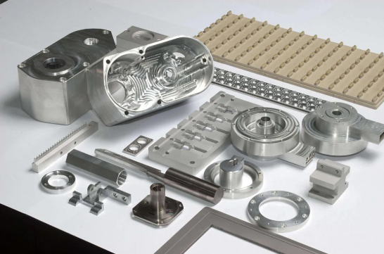
 Maliit na mga batch, mataas na pamantayan. Ang serbisyo sa paggawa ng mabilis na prototyping namin ay gumagawa ng mas mabilis at mas madali ang pagpapatunay —

Pag-unawa sa Wrinkling sa Deep Draw Stamping: Mga Mahahalagang Punto
Pag-unawa sa Pagkakaroon ng Mga Uling sa Malalim na Pagpapadapa
Kapag hinila mo ang isang patag na metal na blank papasok sa isang three-dimensional na hugis, kailangan may bagay na magbibigay. Ang materyal ay lumiliit, tumatagal, at dumadaloy papasok sa loob ng die cavity. Kapag mali ang prosesong ito, nabubuo ang mga uling: mga wave-like na undulasyon na sumisira sa parehong hitsura at istruktural na integridad ng iyong bahagi. Ang depekto na ito ay nananatiling isa sa pinakapananatiling hamon sa pagbuo ng sheet metal malalim na pagpapadapa, na nakaaapekto sa lahat mula sa mga automotive body panel hanggang sa mga lata ng inumin.
Ang pagkakaroon ng mga uring sa malalim na pagpapadapa ay pangunahin ang anyo ng lokal na buckling. Ito ay nangyayari kapag ang compressive stresses sa sheet metal ay lumalampas sa kakayahan ng materyal na labanan ang out-of-plane deformation. Ano ang resulta? Mga fold, wave, o pucker na nagiging sanhi ng pagiging hindi magamit ng mga bahagi o kailangang i-correct sa pamamagitan ng mahal na secondary operations.
Ano ang Pagkakaroon ng Mga Uling sa Malalim na Pagpapadapa
Sa pangunahin, ang kahinaang ito ay isang problema sa instabilitya. Habang pinipilit ng punch ang blank na pumasok sa loob ng die cavity, ang rehiyon ng flange ay nakakaranas ng radial tensile stress na hinihila ito papaloob samantalang nangyayari naman ang circumferential compressive stress dahil sa pagbaba ng diameter nito. Kapag ang compressive hoop stress na ito ay naging sobrang mataas, ang sheet ay nabubuwal.
Ang pagkabuo ng mga ugat (wrinkling) ay nagsisimula kapag ang compressive circumferential stress sa flange ay lumampas sa lokal na buckling resistance ng materyal, na nagdudulot ng out-of-plane na pagbuwal ng sheet.
Ang prinsipyong mekanikal na ito ang nagpapaliwanag kung bakit mas madaling mag-ugat (wrinkle) ang mas manipis na sheet kaysa sa mas makapal na mga sheet, at kung bakit ang ilang grado ng materyal ay mas sensitibo sa depekto na ito kaysa sa iba. Ang blank holder ay gumagamit ng pababang presyon upang tiyak na labanan ang tendensya ng pagbuwal, ngunit ang paghahanap ng tamang balanse ang tunay na hamon sa engineering.
Flange Wrinkling vs. Wall Wrinkling — Dalawang Hiwalay na Mode ng Pagkabigo
Hindi lahat ng mga ugat ay pareho. Ang pag-unawa kung saan sila nabubuo ang unang hakbang patungo sa paglutas nila. Ang pananaliksik na inilathala sa Journal of Materials Processing Technology ay nagkakategorya ng depekto na ito sa dalawang uri na may magkaibang mekanikal na katangian:
- Ang pag-ugat sa gilid (flange wrinkling) ay nangyayari sa patag na bahagi ng blank na nananatili sa pagitan ng blank holder at die habang isinasagawa ang drawing. Ang lugar na ito ay nakakaranas ng diretsong compressive stress habang dumadaloy ang materyal papa-loob.
- Ang pag-ugat sa pader (wall wrinkling) ay nabubuo sa nakadrawing na sidewall o pader ng cup matapos dumaloy ang materyal sa ibabaw ng die radius. Ang rehiyon na ito ay relatibong walang suporta mula sa tooling, kaya mas madaling mag-buckle sa ilalim ng mas mababang antas ng stress.
Ang dalawang mode ng pagkabigo na ito ay may parehong ugat na sanhi, ang compressive circumferential stress, ngunit sumasagot sila sa iba't ibang corrective actions. Mas madali pangyari ang wall wrinkling kaysa flange wrinkling dahil ang sidewall ay kulang sa direktang pagsasala na ibinibigay ng blank holder. Mahirap supilin ang wall wrinkles sa pamamagitan ng pag-aadjust ng blank holder force dahil ang puwersa ay nakaaapekto pangunahin sa radial tensile stress imbes na direktang magpapigil sa wall.
Kaya narito ang pangunahing tanong na dapat gabay sa iyong pagtukoy sa problema: saan nabubuo ang mga ugat ng iyong mga wrinkling? Ang sagot ang magtutukoy sa iyong diagnostic path at sa mga solusyon na dapat isaalang-alang. Ang isang wrinkle sa periphery ng flange ay nagpapahiwatig ng hindi sapat na blank holder force o isang sobrang laking blank. Ang isang wrinkle sa drawn wall ay nagpapahiwatig ng sobrang malawak na punch-die clearance o kulang na suporta sa wall. Ang pagtrato sa mga ito bilang palitan ng mga problema ay humahantong sa pagkawala ng oras at patuloy na scrap.
Sa buong artikulong ito, paulit-ulit nating babalikan ang pamamaraang pang-diagnosis na batay sa lokasyon. Kung ikaw ay nagsisilbi sa paggawa ng bakal o sa paggawa ng mga bahagi ng metal na may mataas na kahusayan, ang mga batas ng pisika ay nananatiling pareho. Ang depekto ang nagpapakita kung saan dapat tingnan; ang iyong tungkulin ay intindihin kung ano ang sinasabi nito sa iyo.
Ang Mekanika sa Likod ng Pagkakaroon ng mga Ulo-ulo
Ang pag-unawa kung bakit nabubuo ang mga ulo-ulo ay nangangailangan ng pagsusuri sa nangyayari sa metal habang isinasagawa ang draw stroke. Imahein ang blank flange bilang isang annular ring na hinahatak paitaas patungo sa punch. Habang ang panlabas na diameter ay sumusukat, ang circumference ay kailangang mabawasan din. Ang materyal na iyon ay kailangang ilipat saanman, at kapag hindi ito maipapadaloy nang maayos, ito ay lumulukab o lumulukab pababa, na lumilikha ng mga ulo-ulo.
Parang kumplikado? Sa katunayan, simple lang ito kapag hinati mo ito. Ang flange ay nakakaranas ng dalawang magkasalungat na stress nang sabay-sabay: radial tensile stress na hinahatak ang materyal patungo sa kavidad ng die, at ang pabilog na compressive stress na nanghihigpit sa materyal habang ang perimeter nito ay sumusukat. Kapag ang compressive hoop stress ay lumampas sa kakayahan ng sheet na labanan ang depekto sa labas ng eroplano, nagsisimula ang buckling.
Compressive Hoop Stress at Buckling — Ang Pangunahing Sanhi na Mekanikal
Isipin ito tulad ng pagpindot sa isang walang laman na aluminum can mula sa taas. Ang cylindrical na pader ay nabubuckling palabas dahil ang compressive load ay lumampas sa resistensya ng manipis na pader sa lateral na deflection. Ang parehong prinsipyo ang nalalapat sa flange habang ginagawa ang deep drawing, maliban sa compression ay kumikilos nang pabilog imbes na axial.
Tatlong heometrikong at materyal na kadahilanan ang namamahala kung gaano kadali ang sheet na mabuckling sa ilalim ng compressive stress na ito:
- Kapal ng sheet: Mas madaling mabuckling ang mas manipis na sheet dahil ang kakayahan laban sa buckling ay nakasukat sa ikatlong kapangyarihan ng kapal. Ang isang sheet na kalahati ang kapal ay mayroon lamang isang-kawalo ang kakayahan laban sa buckling.
- Kakatigan ng materyal (elastic modulus): Ang mga materyal na may mas mataas na modulus ay mas epektibong tumututol sa elastic buckling. Dahil dito, ang mga aluminum alloy, na may halos isang ikatlo lamang na elastic modulus kumpara sa bakal, ay likas na mas madaling mag-krinko sa katumbas na kapal.
- Lapad ng di-nakasuportahang flange: Ang distansya sa pagitan ng bukas na bahagi ng die at ng gilid ng blank ang nagtatakda kung gaano kalaki ang bahagi ng materyal na malayang makakabuckling. Mas malawak na di-nakasuportahang lugar ang nangangahulugan ng mas mababang resistance sa buckling, na katulad ng kung paano ang isang mas mahabang haligi ay nabubuckling sa ilalim ng mas kaunti lamang na load kumpara sa isang mas maikli.
Pananaliksik mula sa Unibersidad ng Estado ng Ohio ipinakita nila ang relasyong ito nang eksperimental gamit ang mga aluminum blank na AA1100-O. Kapag ang blank holder force ay itinakda sa zero, ang flange ay agad na nag-krinko halos kaagad pagkatapos simulan ang pagbuo. Habang dumarami ang pwersang pumipigil, ang pagkakarinko ay inilipat sa mas huli, at kapag lumampas ito sa isang kritikal na threshold, ang mga krinko ay lubos na napigilan.
Paano Nakaaapekto ang mga Katangian ng Materyal sa Panganib ng Pagkakarinko
Nito ang kung saan naging isang kasangkapan sa pagsusuri ang iyong sheet ng datos ng materyal. Ang tatlong katangian ay direktang nakaaapekto sa paraan kung paano tumutugon ang isang materyal sa mga compressive stresses na nagdudulot ng mga ugat o wrinkles: yield strength, strain hardening exponent (n-value), at plastic anisotropy (r-value).
Ang yield strength ay tumutukoy sa antas ng stress kung saan nagsisimula ang plastic deformation. Ang mga materyal na may mas mababang yield strength ay pumasok sa plastic flow nang mas maaga sa loob ng draw stroke, na maaaring tunay na tumulong sa pagpapakalat muli ng stress at pagpapaliban ng buckling. Ang eksperimental na gawain sa mga komersyal na malinis na aluminum na grado ay natuklasan na ang mga alloy na may mas mababang yield stress ay nagpakita ng mas mahusay na paglaban laban sa wrinkling, basta’t ang iba pang katangian ay angkop.
Ang halaga ng n, o eksponente ng pagpapalakas dahil sa pagkabuo, ay naglalarawan kung gaano kabilis ang materyal ay lumalakas habang ito ay nabubuo. Ang mga materyal na may mataas na halaga ng n ay nagpapamahagi ng pagkabuo nang mas pantay sa buong gilid kaysa sa pagtutuon ng dehormasyon sa mga lokal na lugar. Ang pantay na pamamahagi ng pagkabuo ay binabawasan ang posibilidad ng lokal na pagkabuko. Ayon sa MetalForming Magazine, ang pagpapalakas dahil sa paggawa na tinutukoy ng halaga ng n ay binabawasan ang posibilidad ng lokal na pagpapalabnaw sa mga bahagi na lubhang nabuo. Ang parehong prinsipyo ay nalalapat din sa pagkakaroon ng mga ugat o riples: ang mga materyal na nagpapalakas nang pantay ay tumututol sa mga lokal na hindi pagkakapantay-pantay na nagpapasimula ng pagkabuko.
Ang r-value, o ratio ng plastic anisotropy, ay nagpapakita kung paano tumutol ang isang materyal sa pagmumulat kung ihahambing sa deformation sa loob ng eroplano. Ang mga materyal na may mataas na r-value ay mas nangunguna sa pag-deform sa loob ng eroplano ng sheet kaysa sa pagdaan sa kapal nito. Mahalaga ito para sa pagkakaroon ng mga wrinkles dahil ang pagpapanatili ng kapal ng flange ay nagpapanatili ng kakayahang tumutol sa buckling sa buong draw stroke. Ang isang materyal na mabilis na lumalamig ay nawawala ang kakayahang tumutol sa compressive buckling habang tumatagal ang operasyon.
Malinaw ang mga ugnayang direksyonal:
- Mas mataas na n-value = mas pantay na distribusyon ng strain = mas mahusay na pagtutol sa pagkakaroon ng wrinkles
- Mas mataas na r-value = mas kaunti ang pagmumulat = panatiling epektibo ang kakayahang tumutol sa buckling sa buong stroke
- Mas mababang yield strength (kasama ang sapat na n-value) = mas maagang plastic flow = mas mahusay na redistribution ng stress
Ang mga relasyong ito ang nagpapaliwanag kung bakit ang pagpili ng materyal ay hindi lamang tungkol sa lakas. Ang isang mataas na lakas na bakal na may limitadong paghaba at mababang halaga ng n ay maaaring mas madaling magkaburak-burak kaysa sa isang mas mababang antas ng lakas na may napakagandang katangian sa pagbuo. Ang parehong lohika ay nalalapat kapag kinukumpara ang bakal sa aluminum: kahit na ang pag-welding o pag-uugnay ng aluminum ay hindi isang problema, ang mas mababang elastic modulus ng mga alloy ng aluminum ay nangangailangan ng iba’t ibang paraan ng proseso upang pigilan ang pagkaburak-burak.
Kapag itinatag na ang mga pangunahing mekanikal na prinsipyo, ang susunod na tanong ay naging praktikal: paano nakaaapekto ang draw ratio at geometry ng blank sa kung kailan at saan nagsisimula ang pagkaburak-burak?
Ang Draw Ratio at Geometry ng Blank Bilang mga Variable sa Pagkaburak-burak
Ngayon na naiintindihan na ninyo ang compressive stresses na nagpapadala sa pagbuo ng mga ugat, ang susunod na tanong ay praktikal: gaano karaming materyal ang maaari ninyong talagang i-draw bago maging hindi na kayang kontrolin ang mga stress na iyon? Ang sagot ay nakasalalay sa dalawang magkaugnay na variable na madalas na binabale-wala ng maraming inhinyero hanggang sa lumitaw ang mga problema sa shop floor: draw ratio at blank geometry .
Isipin ninyong sinusubukan ninyong hilahin ang isang malaking bilog na tablecloth sa pamamagitan ng isang maliit na singsing. Ang higit na dami ng tela na inilalagay ninyo ayon sa lapad ng singsing, ang higit na maraming materyal ang magkakabundol at magkakapiko. Pareho ang paraan ng deep drawing. Ang ugnayan sa pagitan ng sukat ng inisyal na blank at ng huling diameter ng punch ang tumutukoy kung gaano karaming circumferential compression ang dapat abutin ng flange, at kung nananatili ba ito sa loob ng kontroladong limitasyon o nag-trigger ng buckling.
Draw Ratio at ang Epekto Nito sa Pagsisimula ng Pag-ugat
Ang limiting drawing ratio (LDR) ay tumutukoy sa pinakamataas na ratio ng diameter ng blanko sa diameter ng punch na maaaring matagumpay na i-draw nang walang kabiguan. Kapag lumampas ka sa threshold na ito, ang dami ng materyal sa flange na kinokompress ay naging sobrang malaki. Ang resulting hoop stress ay lumulubog sa buckling resistance ng sheet, at ang mga ugat o wrinkles ay nabubuo anuman ang lakas ng blank holder force na iyong ilalagay.
Ito ang dahilan kung bakit ito mahalaga: habang tumataas ang draw ratio, mas maraming materyal ang kailangang dumaloy paitaas sa bawat stroke. Ang karagdagang materyal na ito ay nagdudulot ng mas mataas na circumferential compression sa flange. Kung sapat ang laki ng drawing punch kung ihahambing sa gilid ng blanko, ang compression ay nananatiling limitado at ang materyal ay dumadaloy nang maayos. Ngunit kapag sobrang malaki ang blanko kung ihahambing sa diameter ng punch, ang labis na compression ay nagdudulot ng resistensya sa daloy na hindi kayang lampasan ng proseso.
Ang pwersang kailangan upang hilumin ang materyal papasok sa die ay tumataas kasabay ng draw ratio. Sa isang tiyak na punto, ang radial tensile stress na kailangan upang labanan ang compression sa flange ay lumalampas sa kayang tustusan ng materyal nang hindi masyadong manipis o sumira sa punch nose. Gayunpaman, bago marating ang threshold ng pagsira, ang pagkukurba (wrinkling) ay karaniwang lumilitaw muna dahil sa pagkabuko (buckling) ng flange sa ilalim ng sobrang compressive load.
Ito ang dahilan kung bakit mahalaga ang pagkalkula ng sukat ng blank gamit ang mga paraan batay sa surface area imbes na sa mga linear na sukat. Ang isang bilog na cup na nabubuo pangunahin sa pamamagitan ng compression ay nangangailangan ng diameter ng blank na malaki ang pagkakaiba sa linear na distansya sa buong nabuong bahagi. Ang sobrang pagtataya sa sukat ng blank batay sa mga dimensyon ng bahagi imbes na sa mga kinakailangan ng daloy ng materyal ay isa sa pinakakaraniwang sanhi ng mga problema sa pagkukurba (wrinkling).
Optimisasyon ng Hugis ng Blank upang Kontrolin ang Daloy ng Materyal
Para sa mga bilog na sisidlan, ang ugnayan sa pagitan ng blank at punch ay direkta. Ngunit ano ang mangyayari kapag gumagawa ka ng mga parihabang kahon, mga panel na may hugis, o mga di-simetrikong anyo? Dito nagsisimula ang pag-optimize ng hugis ng blank bilang isang kapaki-pakinabang na kasangkapan upang kontrolin ang pagkukurba, at kung saan maraming operasyon sa pagpapalipad ng metal ang nawawalan ng potensyal na pagganap.
Na-publish na pananaliksik sa Pandaigdigang Jornal ng Advanced Manufacturing Technology ipinapakita na ang pag-optimize ng paunang hugis ng blank para sa mga parihabang bahagi ay nababawasan ang basura at pinabubuti ang kahusayan sa pagbuo. Ang pag-aaral ay natuklasan na ang pagsasama ng anisotropic na katangian ng materyales sa pag-optimize ng blank ay binawasan ang error sa kontur mula sa 6.3 mm patungo sa 5.6 mm, na nakamit ang kabuuang error na nasa ilalim ng 4 porsyento.
Ang prinsipyo ay simple: ang mga di-bilugang blanko para sa mga di-simetrikong bahagi ay sumusuri kung gaano karaming materyal ang pumapasok sa die sa bawat lokasyon. Ang isang hugis na blanko na sumusunod sa linya ng pagbukas ng punch ay mas malaya ang daloy kaysa sa isang parihabang o trapezoidal na blanko na may sobrang materyal sa mga sulok. Ayon sa paliwanag ng FormingWorld, ang karagdagang materyal sa labas ng mga rehiyon ng pagguhit sa sulok ay naghihigpit sa daloy ng materyal, samantalang ang hugis na blanko na sumusunod sa heometriya ay mas malaya ang daloy.
Isipin ang isang B-pillar o katulad na bahagi ng istruktura ng sasakyan. Ang isang trapezoidal na sheared blanko ay maaaring mas murang gawin dahil hindi nito kailangan ang espesyal na blanking die. Gayunpaman, ang sobrang materyal sa mga rehiyon ng sulok ay lumilikha ng karagdagang paghihigpit sa daloy ng metal. Ang hugis na blanko ay mas malapit na sumusunod sa pagbukas ng punch, na binabawasan ang paghihigpit at pinapahintulutan ang materyal na dumaloy papasok sa mga sulok para sa mas mahusay na formability at nababawasan ang panganib ng pagkakaroon ng mga ugat o wrinkling.
Ang mga sobrang laki na blanko ay karaniwang sanhi ng pagkukurba na minsan ay nakakaligtaan ng mga koponan sa produksyon. Kapag ang blanko ay mas malaki kaysa inaasahan, mas mabagal ang daloy ng materyal papasok sa mga sulok at mas malaki ang kontak nito sa binder. Ito ay nagdudulot ng mas mataas na pagpigil mula sa puwersa ng blank holder at sa panlabas na pwersa (friction). Ang resulta ay mas mataas na compressive stress sa flange at mas malaking posibilidad ng pagkukurba. Sa kabaligtaran, ang mga sobrang liit na blanko ay maaaring dumaloy nang labis, kaya nababawasan ang nais na pagpapahaba (stretching) at maaaring umalis sa draw beads bago makarating sa ilalim.
Ang ilang mga salik sa geometry ng blanko ay direktang nakaaapekto sa panganib ng pagkukurba:
- Diameter ng blanko kung ihahambing sa diameter ng punch: Ang mas mataas na ratio ay nangangahulugan ng higit pang materyal sa estado ng compression at mas malaking posibilidad ng pagkukurba. Panatilihin ang ratio sa loob ng LDR para sa iyong uri ng materyal.
- Simetriya ng hugis ng blanko kung ihahambing sa geometry ng bahagi: Ang mga blankong may hugis na sumusunod sa mga kontur ng bukas na bahagi ng punch ay nababawasan ang labis na materyal sa mga lugar na may mataas na compression.
- Dami ng materyal sa sulok sa mga blankong rectangular: Ang mga sulok ay nakakaranas ng mas mataas na compressive stress kaysa sa mga tuwid na gilid. Ang labis na materyal sa sulok ay pinalalakas pa ang epekto na ito.
- Pagkakapantay-pantay ng lapad ng flange: Ang hindi pantay na lapad ng flange ay nagdudulot ng hindi pantay na distribusyon ng compression, na humahantong sa lokal na pagkukurba (wrinkling) sa mga mas malawak na lugar.
Ang work-hardened na materyal mula sa mga nakaraang operasyon sa pagbuo ay nakaaapekto rin kung paano tumutugon ang mga blank sa compression. Kung ang materyal ay naka-strain hardened na dahil sa nakaraang proseso, bumababa ang kakayahang mag-deform nang pantay. Maaari itong makapitik sa agwat sa pagitan ng pagsisimula ng pagkukurba (wrinkling) at ng pagkabigo dahil sa pagsira (tearing), kaya lalo pang napapahalagahan ang optimal na geometry ng blank para sa mga multi-stage na operasyon.
Ano ang praktikal na kinalabasan? Ang hugis ng blanko ay hindi lamang isang desisyon tungkol sa paggamit ng materyal. Direktang kontrolado nito ang pamamahagi ng compressive stress sa iyong flange at tumutukoy kung ang iyong proseso ay gumagana nang ligtas sa loob ng threshold ng wrinkling o patuloy na nakikipaglaban sa mga depekto dulot ng buckling. Kapag naunawaan na ang draw ratio at ang hugis ng blanko, ang susunod na hakbang ay ang pagsusuri kung paano ang mga parameter ng tooling ay nagbibigay ng direktang kontrol sa wrinkling habang isinasagawa ang operasyon ng pagbuo.
Mga Parameter ng Tooling na Kontrolado o Nagdudulot ng Wrinkling
Napag-optimize mo na ang hugis ng iyong blanko at pinili ang isang materyal na may magandang katangian sa formability. Ano ang susunod? Ang mismong tooling ang naging pangunahing mekanismo mo para kontrolin ang wrinkling habang isinasagawa ang aktwal na operasyon ng pagbuo. Bawat parameter na itinakda mo—mula sa blank holder force hanggang sa die radius geometry—ay direktang nakaaapekto kung ang iyong flange ay mabubuckle o mabubuo nang maayos at pabilog papasok sa loob ng die cavity.
Ito ang hamon na karamihan sa mga inhinyero ang kinakaharap: ang mga parehong pag-aadjust na pumipigil sa pagkukurba ay maaaring mag-trigger ng pagkabulok kung isasagawa nang labis. Hindi ito isang optimization problem na may iisang variable. Ito ay isang pagbabalanse kung saan ang bawat parameter ng tooling ay nasa isang spektrum sa pagitan ng dalawang uri ng kabiguan. Ang pag-unawa kung saan nasa spektrum na iyon ang inyong proseso, at kung paano ito nababahagi, ang naghihiwalay sa pare-parehong produksyon mula sa paulit-ulit na mga isyu sa kalidad.
Pwersa ng Blank Holder — Pagbabalanse ng Pagkukurba Laban sa Pagkabulok
Ang pwersa ng blank holder (BHF) ang pangunahing kontrol na variable para sa pagkukurba sa flange. Ang blank holder ay naglalapat ng pababang presyon sa flange, na lumilikha ng panlabas na panlaban (friction) na humihinto sa daloy ng materyal at nagbubuo ng radial na tensile stress sa sheet. Ang tensyon na ito ay sumasalungat sa circumferential na compression na nagdudulot ng buckling.
Kapag ang BHF ay napakababa, kulang ang flange sa sapat na panlaban. Ang compressive hoop stress ay lumalampas sa kakayahang tumanggap ng buckling ng sheet, at ang mga kurba ay nabubuo. Habang Ang Tagagawa mga tala, ang hindi sapat na presyon ng blank holder ay nagpapahintulot sa metal na magkabuhol kapag inilalagay sa kompresyon, at ang nabuhol na metal ay nagdudulot ng paglaban sa daloy, lalo na kapag nakakulong sa gilid na pader.
Kapag ang BHF ay sobrang mataas, ang kabaligtaran na problema ang lumalabas. Ang labis na presyon ay naglilimita sa daloy ng metal patungo sa loob, kaya't ang materyal ay hinahatak imbes na inilalabas. Ang paghahatak na ito ay pumapalabas sa sheet sa radius ng punch nose, na humahantong sa pagkabulok. Ang parehong sanggunian ay binibigyang-diin na ang labis na presyon ng blank holder ay naglilimita sa daloy ng metal, na nagdudulot ng paghahatak nito, na maaaring magresulta sa pagkabulok.
Ano ang praktikal na implikasyon nito? Ang BHF ay dapat sapat na mataas upang pigilan ang pagkabigat (buckling) ngunit sapat na mababa upang payagan ang daloy ng materyal. Ang saklaw na ito ay nag-iiba depende sa grado ng materyal, kapal ng sheet, at lalim ng pagguhit. Para sa mga materyal na may limitadong paglalawig, tulad ng mga advanced high-strength steels, ang saklaw na ito ay napakapipit. Mayroon kang mas kaunting kaluwagan para sa kamalian bago lumipat mula sa lugar kung saan nabubuo ang mga ugat (wrinkling) patungo sa lugar kung saan nabubura ang materyal (tearing).
Mahalaga ang pamamahagi ng presyon gaya ng kabuuang puwersa. Ang mga press cushion na hindi maayos na pinapanatili o ang mga nasirang cushion pin ay nagdudulot ng hindi pantay na presyon sa buong ibabaw ng blank holder. Ito ay nagdudulot ng lokal na labis na paghihigpit sa ilang lugar at kulang na paghihigpit sa iba, na nagreresulta sa parehong mga ugat (wrinkles) at punit (splits) sa iisang bahagi. Ang mga equalizer ay tumutulong na panatilihin ang tiyak na agwat sa pagitan ng die face at blank holder anuman ang pagbabago ng presyon, ngunit kailangan nilang kalibratin nang regular upang gumana nang tama.
Die Radius, Punch Radius, Clearance, at Disenyo ng Draw Bead
Bukod sa BHF, may apat pang mga parameter ng tooling na direktang nakaaapekto sa pag-uugat (wrinkling): radius ng die entry, radius ng punch nose, clearance ng punch-die, at disenyo ng draw bead. Ang bawat isa ay may sariling kompromiso sa pagitan ng panganib ng pag-uugat at panganib ng punit (tearing).
Ang radius ng pumasok na bahagi ng die ay nagtatakda kung gaano kalakas ang pagkabaluktot ng materyal habang ito ay lumilipat mula sa flange papunta sa nakadrawing na pader. Ang mas malaking radius ay binabawasan ang katapangan ng pagkabaluktot, na nagpapababa ng puwersa ng pagdrowing at panganib ng pagputok. Gayunpaman, ito ay nagpapataas din ng hindi suportadong lugar ng flange sa pagitan ng gilid ng blank holder at ng bukas na bahagi ng die. Ang mas malaking hindi suportadong lugar na ito ay may mas mababang laban sa pagkabuko, kaya't tumataas ang posibilidad ng pagkakaroon ng mga ugat o rippling. Ang mas maliit na radius ng die ay mas epektibong pinipigilan ang daloy ng materyal, ngunit nagpapasentro ng stress sa lugar ng pagkabaluktot, na nagpapataas ng panganib ng pagsira. Toledo Metal Spinning ipinaliliwanag na kung ang radius ng die ay sobrang maliit, hindi madaling dumaloy ang materyal, na nagreresulta sa paglalabas at pagputok nito. Kung ang radius ng die ay sobrang malaki, magkakaroon ng mga ugat o rippling ang materyal pagkatapos umalis sa pinch point.
Sumusunod ang radius ng punso sa parehong lohika. Ang mas malaking radius ng punso ay nagpapakalat ng pormang stress sa mas malawak na lugar, kaya nababawasan ang panganib ng lokal na pagmumulat at pagkaburak. Ngunit ito ay nagpapahintulot din ng higit pang materyal na manatiling hindi suportado sa panimulang yugto ng pagguhit, na maaaring magdulot ng dagdag na panginginig sa transisyong zona sa pagitan ng kontak ng punso at pasukan ng die.
Ang clearance ng tooling sa pagitan ng punso at die ay isang variable para sa panginginig ng pader, hindi para sa panginginig ng flange. Kapag lumampas ang clearance sa kapal ng materyal nang sobra-sobra, ang hinugot na pader ay kulang sa lateral na suporta. Ito ay nagpapahintulot sa sidewall na mag-buckle nang hiwalay sa mga kondisyon ng flange, na nagreresulta sa mga panginginig sa pader kahit na ang flange ay nananatiling walang panginginig. Ang tamang clearance ay karaniwang tinutukoy bilang isang porsyento na higit sa nominal na kapal ng sheet, na sumasaklaw sa pagkapal ng materyal na nangyayari habang ginuguhit.
Ang mga draw bead ay nag-aalok ng tiyak na kontrol na hindi maaaring bigyan ng uniform na BHF adjustment. Ang mga ito ay mga raised na feature sa die face o blank holder na lumilikha ng lokal na pwersang pumipigil sa pamamagitan ng pagbend at unbend ng sheet habang ito ay dumadaloy palapit. Ayon sa pananaliksik mula sa Oakland University, ang pwersang pumipigil ng draw bead ay maaaring baguhin nang humigit-kumulang sa apat na beses lamang sa pamamagitan ng pag-aadjust sa lalim ng bead penetration. Ito ay nagbibigay ng malaking flexibility sa mga designer ng die upang kontrolin ang distribusyon ng daloy ng materyal sa paligid ng perimeter ng blank nang hindi kinakailangang pataasin ang BHF nang pantay sa buong flange.
Ang mga draw bead na nakaposisyon nang estratehiko ay tumutugon sa mga lokal na problema ng pagkukurba na hindi masosolusyunan ng pangkalahatang pag-aadjust ng BHF. Para sa mga bahagi na parihaba kung saan ang mga sulok ay nakakaranas ng mas mataas na compressive stress kaysa sa tuwid na mga gilid, ang mga draw bead sa mga lokasyon ng sulok ay nagpapataas ng lokal na pagpigil nang hindi lumalabis sa pagpigil sa mga tuwid na seksyon. Ang binder force na kailangan upang makamit ang kinakailangang pagpigil ay malaki ang binabawas kapag ginagamit ang mga draw bead, na nangangahulugan na ang mas maliit na press capacity ay maaaring makamit ang katumbas na kontrol sa metal.
| Parameter ng Kagamitan | Epekto sa Pagkukurba | Epekto sa Pagkabura | Pag-aadjust upang Bawasan ang Pagkukurba |
|---|---|---|---|
| Blank Holder Force (BHF) | Ang mababang BHF ay nagpapahintulot sa pagkabuko ng flange | Ang mataas na BHF ay naglilimita sa daloy, na nagdudulot ng mga punit | Pataasin ang BHF sa loob ng hangganan ng pagkabura |
| Radius ng Paggawa ng Die | Ang malaking radius ay nagpapataas ng hindi suportadong lugar | Ang maliit na radius ay nagpapasentro ng stress | Bawasan ang radius habang sinusubaybayan ang pagkakabuhag |
| Punch nose radius | Ang malaking radius ay nagpapababa ng suporta sa maagang hakbang | Ang maliit na radius ay nagdudulot ng lokal na pagpapalapad | Balansin batay sa lalim ng pagguhit |
| Kawalan ng Pagkakasunod-sunod ng Punch at Die | Ang labis na kawalan ng pagkakasunod-sunod ay nagpapahintulot sa pagkabukol ng pader | Ang kulang na kawalan ng pagkakasunod-sunod ay nagdudulot ng stress sa pagpapalapad | Bawasan ang kawalan ng pagkakasunod-sunod upang suportahan ang pader |
| Pagsusulok ng Draw Bead | Ang mga mababaw na bead ay nagbibigay ng hindi sapat na pagpigil | Ang malalim na mga beads ay labis na naghihigpit sa daloy | Pataasin ang pagpasok sa mga lugar na madaling mag-ungos |
Ang pangunahing pananaw mula sa talabang ito ay ang bawat pag-aadjust ng parameter ay may kaukulang kompromiso. Ang paggalaw sa isang direksyon ay pumipigil sa pag-ungos ngunit tumataas ang panganib ng pagputok. Ang paggalaw sa kabaligtaran na direksyon ay gumagawa ng kabaligtaran. Ang matagumpay na pagbuo ng die ay nangangailangan ng paghahanap ng operating window kung saan parehong iwasan ang dalawang uri ng kabiguan, at ang nasabing window ay nag-iiba depende sa materyal, hugis, at antas ng draw.
Ang pag-unawa sa mga relasyong ito ng tooling ay nagha-hahanda sa iyo para sa susunod na hamon: ang pagkilala na ang iba't ibang materyal ay may iba't ibang tugon sa parehong tooling setup. Ang isang die na in-optimize para sa mild steel ay maaaring mag-ungos sa aluminum o magputok sa advanced high-strength steel kung walang pag-aadjust sa mga parameter.
Pag-uugali ng Pag-ungos sa Karaniwang Mga Materyal sa Stamping
Ang isang die na tumatakbo nang perpekto sa mild steel ay maaaring mag-produce ng mga bahagi na may mga ugat o kulubot sa sandaling lumipat ka sa aluminum. Bakit? Dahil ang parehong mga parameter ng tooling ay kumikilos nang iba-iba sa bawat materyal batay sa kanilang mekanikal na katangian. Ang pag-unawa kung paano nagkakaiba ang yield strength, elastic modulus, at strain hardening behavior sa mga karaniwang materyal na ginagamit sa stamping ay mahalaga upang ma-predict ang panganib ng pagkukulubot at i-adjust ang proseso nang naaayon.
Ang sumusunod na talahanayan ay nagtutulad ng pagkukulubot sa loob ng anim na pamilya ng materyal na karaniwang ginagamit sa mga operasyon ng deep draw. Ang bawat rating ay sumasalamin kung paano nakaaapekto ang likas na katangian ng materyal sa kakayahang tumutol sa buckling sa ilalim ng compressive flange stress.
Tendensya sa Pagkukulubot Ayon sa Baitang ng Materyal
| Materyal | Tendensya sa pagkabuhol | Inirerekomendang Paraan ng Paggamit ng BHF | Mga Pangunahing Sensitibidad ng Proseso | Pag-uugali ng Strain Hardening |
|---|---|---|---|---|
| Mild Steel (DC04, SPCC) | Mababa | Katamtaman, stable sa buong stroke | Puwedeng-patawarin; malawak ang window ng proseso | Katamtaman ang n-value; unti-unting humihigpit |
| HSLA Steel | Mababa hanggang Medyo | Katamtaman hanggang mataas; subaybayan ang tearing | Ang mas mataas na lakas ng pagkabigat ay nagpapitik sa window ng BHF | Mas mababa ang halaga ng n kaysa sa mild steel |
| AHSS (DP, TRIP grades) | Katamtaman hanggang mataas | Mataas na paunang BHF; bariyable sa buong stroke | Limitadong paghaba; makitid na window sa pagitan ng pagkakaroon ng wrinkles at pagkakaluma | Mataas na paunang yield; limitadong kakayahan sa work hardening |
| Aluminum 5xxx Series | Mataas | Mas mababa kaysa sa steel; kinakailangan ang tiyak na kontrol | Mababang elastic modulus; sensitibo sa bilis ng pagguhit | Katamtamang halaga ng n; nagkakaroon ng strain hardening habang binubuo |
| Aluminum 6xxx Series | Mataas | Mas mababa kaysa sa bakal; nakasalalay sa temper | Maaaring i-heat-treat; ang pagkakabuo ay nag-iiba depende sa kondisyon ng temper | Mas mababang n-value kaysa sa 5xxx; mas kaunti ang pagkakapantay ng pagkakatigas |
| Hindi kinakalawang na asero 304 | Katamtaman | Mahigh; kailangang dagdagan habang tumatagal ang stroke | Mabilis na work hardening; mataas na friction; sensitibo sa bilis | Napakataas na n-value; agresibong pagkakatigas |
Ang mga rating sa itaas ay sumasalamin kung paano nakikipag-ugnayan ang bawat katangian ng materyal sa compressive stresses na nagdudulot ng buckling. Tingnan natin nang mas malalim kung bakit mahalaga ang mga pagkakaiba na ito sa praktikal na aplikasyon.
Bakit Kailangan ng Aluminum at AHSS ng Iba’t Ibang Pamamaraan sa Paggawa
Ang mga aluminum alloy ay nagbibigay ng natatanging hamon dahil sa kanilang mababang elastic modulus. Ang elastic modulus ng bakal ay nasa paligid ng 200 GPa, samantalang ang aluminum ay nasa paligid ng 70 GPa. Ibig sabihin, ang aluminum ay may humigit-kumulang isang ikatlo lamang na likas na rigidity kumpara sa bakal. Dahil ang kakayahang tumutol sa buckling ay direktang nakasalalay sa rigidity ng materyal, ang isang aluminum sheet na may katumbas na kapal ay mas madaling mag-buckle kaysa sa bakal sa ilalim ng parehong compressive load.
Ang mas mababang paglaban sa pagkabukol na ito ang nagpapaliwanag kung bakit naiiba ang pag-uugali ng aluminum kumpara sa stainless steel habang isinasagawa ang malalim na pagguhit (deep drawing). Hindi tulad ng stainless steel, na maaaring dumaloy at muling ipamahagi ang kapal nito sa ilalim ng puwersa, ang aluminum ay hindi maaaring labis na patagurin o sobrang deform. Ang materyal ay nagkakaroon ng lokal na strain na may limitadong paghaba, na kulang sa pagkakalat ng paghaba na inooffer ng bakal. Ang matagumpay na pagguhit ng aluminum ay nakasalalay sa pagpapanatili ng tamang ratio ng pagguhit at sa eksaktong pagbabalanse ng paghahaba, pagsasampit, at puwersa ng blank holder.
Ang mga aluminong alloy na nasa serye ng 5xxx (tulad ng 5052 at 5182) ay nag-aalok ng mas mahusay na pagkakabuo kumpara sa mga grado ng serye ng 6xxx dahil sa kanilang mas mataas na halaga ng n. Ang eksponente ng pagpapalakas dulot ng pagkakabuo na ito ay nagpapahintulot sa mga alloy ng 5xxx na ipamahagi ang dehormasyon nang mas pantay sa buong gilid, na humihinto sa pagsisimula ng lokal na pagkabigkis. Samantala, ang mga alloy ng serye ng 6xxx (tulad ng 6061 at 6063), bagaman nag-aalok ng mahusay na lakas matapos ang paggamot ng init, ay may mas mababang halaga ng n sa kanilang kondisyon na pinatatae. Dahil dito, mas madaling magkaroon ng lokal na pagkakasentro ng tensyon at mas maagang nagsisimula ang pagkakaroon ng mga ugat o riples.
Ang mga advanced na mataas na lakas na bakal ay nagpapakita ng kabaligtaran ng problema. Ang mga grado ng AHSS tulad ng dual-phase (DP) at transformation-induced plasticity (TRIP) na bakal ay may mataas na yield strength, na kadalasan ay lumalampas sa 500 MPa. Ang mataas na yield stress na ito ay nangangahulugan na ang materyal ay tumututol sa plastic flow, kaya kailangan ng mas mataas na BHF upang pigilan ang pagkakaroon ng mga ugat o wrinkles. Gayunpaman, ang mga grado ng AHSS ay may limitadong kabuuang elongation kumpara sa mild steel. Ayon sa The Fabricator, ang mga problema tulad ng wrinkling, tearing, at springback na nangyayari sa panahon ng pagbuo ng AHSS ay lumilikha ng hamon sa buong supply chain.
Ano ang praktikal na resulta? Ang AHSS ay pumipigil nang malaki sa BHF window. Kailangan mo ng mas mataas na puwersa upang pigilan ang wrinkling, ngunit ang materyal ay sumisira sa mas mababang antas ng strain kumpara sa mild steel. Ito ay nag-iwan ng mas kaunti lamang na margin para sa error. Ang servo press technology na may programmable force profiles ay tumutulong na malutas ang hamong ito sa pamamagitan ng pagpapahintulot sa mga stampers na baguhin ang cushion force sa buong stroke—na nag-aapply ng mas agresibong restraint kung saan kinakailangan at binabawasan ang puwersa kung saan tumaas ang panganib ng tearing.
Ang stainless steel na may grado na 304 ay nagdadagdag ng isa pang salik: mabilis na pagkakabigat ng paggawa. Ang uri ng austenitic na ito ay may napakataas na halaga ng n, na nangangahulugan na ito ay lumalakas nang agresibo habang nababaluktot. Mas mabilis ang pagkakabigat ng paggawa ng stainless steel kaysa sa carbon steel, kaya kailangan ng halos dobleng presyon upang mapagalaw at maporma ito. Ang pelikulang oksido ng chromium sa ibabaw ay nagpapalakas din ng panlabas na pagsalungat (friction) habang pinoporma, kaya kailangang lubusang patubuan at lagyan ng lubricant ang mga tool.
Ano ang kahulugan nito para sa pagkakaroon ng mga ugat o rippling (wrinkling)? Ang mabilis na pagkakabigat ng paggawa ay talagang nakatutulong sa paglaban sa pagkabigkis (buckling) habang tumatagal ang proseso ng pagguhit (drawing), dahil ang materyal ay patuloy na tumitigas. Gayunpaman, ang mataas na antas ng panlabas na pagsalungat at mga kinakailangang presyon ay nangangahulugan na ang BHF (blank holder force) ay dapat dagdagan nang paulit-ulit habang tumatagal ang stroke upang mapanatili ang kontrol. Kung mananatiling pareho ang BHF, maaaring magkaroon ng mga ugat o rippling sa simula ng stroke samantalang magkakaroon ng punit o tearing sa huling bahagi ng stroke. Sa mas malalim na pagguhit, mas mabagal ang kailangang bilis nito upang isama ang mga salik na ito.
Ang relasyon sa pagitan ng yield stress at yield strength ay mahalaga rin dito. Ang mga materyales na may mas mababang paunang yield strength ay pumasok sa plastic flow nang mas maaga, na nagpapahintulot sa redistribution ng stress bago magsimula ang buckling. Ang mga materyales na may mas mataas na yield strength ay tumututol sa maagang daloy na ito, kaya nakakatuon ang stress sa mga lokal na lugar kung saan maaaring magsimula ang buckling bago pa man mag-yield nang pantay ang materyal.
Para sa mga blankong hinugot gamit ang wire EDM o mga bahagi na pinino nang may kahusayan kung saan ang kalidad ng gilid ay nakaaapekto sa daloy ng materyal, ang mga pagkakaiba ng materyal na ito ay lalong lumalabas. Ang isang malinis na gilid ay dumadaloy nang mas maasahan kaysa sa isang gilid na kinuha sa pamamagitan ng shearing na may mga work-hardened na burrs, at ang epekto na ito ay nag-iiba depende sa grado ng materyal.
Ang pangunahing katuwiran? Hindi mo maaaring i-transfer ang mga parameter ng proseso nang direkta mula sa isang materyal papunta sa isa pa. Ang isang die na in-optimize para sa mild steel ay malamang na magpapakurba sa aluminum at maaaring magpaputol sa AHSS. Ang bawat pamilya ng materyal ay nangangailangan ng sariling estratehiya para sa BHF, optimisasyon ng bilis ng pagguhit, at pamamaraan sa paglilipat. Ang pag-unawa sa mga ugali ng materyal na ito bago ang pagputol ng tooling ay nag-iimbak ng malaking oras at gastos sa panahon ng die tryout.
Kapag naunawaan na ang ugali ng materyal, ang susunod na tanong ay naging heometriko: paano binabago ng hugis ng bahagi ang lugar at dahilan ng pagkukurba?
Paano Binabago ng Hugis ng Bahagi ang Lugar at Dahilan ng Pagkukurba
Pumili ka na ng tamang materyal at in-adjust mo na ang mga parameter ng iyong tooling. Ngunit narito ang isang bagay na natutunan ng maraming inhinyero sa pinakamahirap na paraan: ang isang proseso na gumagana nang perpekto para sa mga cylindrical cup ay maaaring ganap na mabigo kapag inilapat sa mga rectangular box o conical shell. Ang hugis ng bahagi ay lubos na binabago ang lugar kung saan nabubuo ang mga kurba, ang dahilan kung bakit sila nabubuo, at kung aling mga aksyon na pangkoreksyon ang talagang epektibo.
Isipin ito sa ganitong paraan. Ang isang cylindrical cup ay may uniform na symmetry sa buong perimeter nito. Ang materyal ay dumadaloy paitaas nang pantay mula sa lahat ng direksyon, at ang compressive stress ay nakadistribute nang pantay sa paligid ng flange. Ang isang rectangular box? Lubos na ibang kuwento. Ang mga sulok ay nakakaranas ng lubos na magkakaibang kondisyon ng stress kumpara sa mga tuwid na gilid. Ang isang conical shell? Ang hindi suportadong area ng pader sa pagitan ng punch at die ay lumilikha ng panganib ng wrinkling na hindi ma-address ng mga kontrol na nakatuon sa flange.
Ang pag-unawa sa mga mekanikong partikular sa geometry na ito ay mahalaga upang ma-diagnose nang tama ang mga problema at mailapat ang tamang solusyon.
Mga Cylindrical, Box, at Conical na Bahagi — Iba't Ibang Mekanika ng Wrinkling
Para sa mga silindrikal na tasa, ang pagkukurba ay kumikilos nang may pananaw. Ang depekto ay simetriko at pangunahing isang pangyayari sa gilid ng metal. Ayon sa paliwanag ng The Fabricator, ang isang silindro ay nagsisimula bilang isang simpleng bilog na blanko, at upang mabago ang mas malawak na diameter ng blanko sa mas maliit na hugis ng silindro, kailangan nitong mag-compress nang radial. Ang metal ay dumadaloy paitaas patungo sa sentral na linya habang nagco-compress din ito nang sabay-sabay. Ang kontroladong compression ay nagreresulta sa isang patag na gilid; ang di-kontroladong compression ay nagdudulot ng matinding pagkukurba.
Ang pangunahing mga kontrol para sa mga silindrikal na bahagi ay ang puwersa ng blank holder at ang draw ratio. Dahil ang distribusyon ng stress ay pantay-pantay, ang global na pag-aadjust ng BHF ay gumagana nang epektibo. Kung lumitaw ang mga kurba, ang pagtaas ng BHF sa buong gilid ay karaniwang nakakaresolba ng problema, basta’t nananatili ka sa ilalim ng threshold ng pagputok. Ang draw ratio ang tumutukoy kung gaano kalaki ang compression na dapat abutin ng gilid, kaya ang pag-iingat sa loob ng limiting drawing ratio para sa iyong materyal ay nakakaiwas sa sobrang compressive load.
Ang mga bahagi ng kahon na may hugis parisukat at parihaba ay nagdudulot ng di-simetriya na nagbabago sa lahat. Ang mga sulok ng isang parisukat na hugis ay literal na isang-kapat ng bilog na hugis, kung saan nararanasan ang radial na compression na katulad sa mga cylindrical na cup. Ngunit ang mga tuwid na gilid ay kumikilos nang iba. Ayon sa parehong pinagkukunan, ang mga pader sa gilid ng isang binuo (drawn) na kahon ay nasa estado ng pagpapaliko at pagpapabango (bend-and-straighten deformation) na may kaunting o walang compression. Ang metal ay dumadaloy paitaas nang may napakaliit na pagtutol sa loob ng mga tuwid na bahagi.
Ang di-simetriyang ito ay lumilikha ng isang mahalagang problema: ang mga rehiyon ng sulok ay nakakaranas ng mas mataas na compressive stress kaysa sa mga tuwid na gilid, kaya ang pagkukurap (wrinkling) sa mga sulok ang pangunahing problema. Kung masyadong maraming surface area ng metal ang pilit na ipinapasok sa radial na compression sa mga sulok, ito ay nagdudulot ng malaking pagtutol sa daloy, na humahantong sa labis na pagkabuwis at posibleng pagputol. Ang mga sulok ay nais kumurap samantalang ang mga gilid ay nais dumaloy nang malaya.
Ang mga pangunahing kasangkapan para sa mga bahagi na may hugis-parihaba ay ang mga draw bead sa mga sulok at ang pag-optimize ng hugis ng blank. Ang mga draw bead ay nagpapataas ng lokal na pwersa ng pagpigil sa mga lokasyon ng sulok nang hindi labis na pinipigilan ang mga tuwid na seksyon. Ang pag-optimize ng hugis ng blank ay binabawasan ang sobrang materyal sa mga rehiyon ng sulok. Kapag gumagamit ng parisukat na blank para gumawa ng isang parisukat na shell, isaalang-alang ang pag-ayos nito nang 45 degree na anggulo na may kaugnayan sa oryentasyon ng bahagi. Ito ay nagdudulot ng mas mataas na paglaban sa daloy sa mga gilid, kung saan higit na kailangan ang tensyon, at mas kaunting materyal sa mga sulok upang tulungan ang maksimum na daloy sa radial na profile.
Ang mga conical shell ay nagbibigay ng isa pang hamon. Ayon sa MetalForming Magazine, ang malalim na pagguhit ng mga hugis-conical ay lubhang mas mahirap kumpara sa mga cylindrical cup dahil ang dehormasyon ay hindi limitado lamang sa rehiyon ng flange. Para sa mga hugis na ito, ang dehormasyon ay nangyayari rin sa hindi suportadong rehiyon sa pagitan ng die at ng punch face kung saan ang compressive stresses ay maaaring magdulot ng mga puckers.
Ang puckering ay tumutukoy sa mga ugat ng pagkakapal na nabubuo sa katawan ng blank dahil sa pagpapahaba, na kabaligtaran ng mga ugat ng pagguhit na nangyayari sa gilid ng blank. Ito ay ugat sa pader imbes na ugat sa tabi, at nangangailangan ng iba't ibang solusyon. Ang bahagi ng pader na walang suporta sa pagitan ng punch at die ay malaki sa mga conical draw, kaya ang ugat sa pader ang pangunahing anyo ng problema. Dapat iwasan ang puckering dahil karaniwang hindi maaalis ang mga ugat na ito.
Para sa mga conical shell, ang ratio ng kapal ng sheet sa diameter ng blank (t/D) ay may mas malaking epekto sa limiting draw ratio kaysa sa cup drawing. Kapag ang t/D ay higit sa 0.25, karaniwang maabot ang isang draw gamit ang normal na blankholder pressure. Kapag ang t/D ay nasa pagitan ng 0.15 at 0.25, maaaring pa ring maisagawa ang isang draw ngunit nangangailangan ng mas mataas na blankholder pressure. Ang t/D na mas mababa sa 0.15 ay nagiging napaka-sensitive ng blank sa pagkakaroon ng ugat at nangangailangan ng maramihang draw reductions.
Ang mga kumplikadong panel na may hugis na may kontur, na karaniwang ginagamit sa mga bahagi ng katawan ng sasakyan, ay nagkakasama ng mga elemento ng lahat ng mga hugis na ito. Ang pagkukurba (wrinkling) ay nakabase sa hugis at nakadepende sa lokasyon, at nagbabago sa buong ibabaw ng bahagi batay sa lokal na kurbatura, lalim ng pagguhit (draw depth), at mga pattern ng daloy ng materyal. Karaniwang kailangan ng mga bahaging ito ang simulation ng pagbuo upang mahulaan kung saan magkakaroon ng pagkukurba at alin sa mga pag-aadjust sa proseso ang magiging epektibo.
Narito ang mga konsiderasyon sa pagkukurba na nakabase sa hugis para sa bawat uri ng bahagi:
- Mga cylindrical cups: Ang pagkukurba ay simetriko at dominado ng flange. Ang BHF at draw ratio ang pangunahing mga kontrol. Ang pangkalahatang pag-aadjust ng BHF ay epektibo. Panatilihin ang LDR para sa iyong grado ng materyal.
- Mga rectangular/box parts: Ang mga sulok ay nakakaranas ng mas mataas na compressive stress kaysa sa mga tuwid na gilid. Ang pagkukurba sa mga sulok ang pangunahing problema. Gamitin ang draw beads sa mga sulok at i-optimize ang hugis ng blank upang mabawasan ang dami ng materyal sa mga sulok. Isaalang-alang ang 45-degree na orientasyon ng blank.
- Mga konikal na kabaong: Ang malaking hindi suportadong lugar ng pader ay nagiging sanhi ng pagkukurap (puckering) ng pader bilang pangunahing anyo. Ang ratio ng t/D ay mahalaga sa pagtukoy sa posibilidad ng pagkukurap. Ang manipis na mga blanko kung ihahambing sa diameter ay nangangailangan ng maraming pagbawas sa pagguhit o ng mga pansamantalang suportang singsing.
- Mga kumplikadong panel na may hugis na may kontur: Ang pagkukurap ay nakabase sa lokasyon at partikular sa heometriya. Kinakailangan ang simulasyon upang hulaan ang mga lokasyon ng kurap. Ang lokal na pagbabago ng BHF at ang paglalagay ng draw bead ay dapat i-customize para sa mga tiyak na lugar na may mataas na panganib.
Mga Epekto ng Pagguhit sa Maraming Yugto at ng Pansamantalang Pagpapainit
Kapag ang isang solong operasyon ng pagguhit ay hindi kayang makamit ang kinakailangang lalim nang walang pagkukurap o pagputol, ang mga sekwensya ng pagguhit sa maraming yugto ay naging kinakailangan. Ito ay lalo na karaniwan sa mga malalim na konikal na kabaong, sa mga hugis na may matinding taper, at sa mga bahagi na nangangailangan ng kabuuang pagbawas na lampas sa kayang ibigay ng isang solong stroke.
Ang matagumpay na pagguhit ng mga shell na may mataas na taper at may ratio ng taas sa diameter na higit sa 0.70 ay nangangailangan ng pamamaraan na tinatawag na stepped-cup approach. Ang deep drawing ng mga stepped cup ay kahalintulad sa cylindrical cup drawing, kung saan ang draw reduction para sa bawat sumunod na hakbang ay katumbas ng kaukulang diameter ng cup. Ang redraw operation ay tumitigil nang bahagya upang itatag ang kaukulang hakbang, at ang shell ng hakbang ay ginuguhit nang pabilog papunta sa isang cone sa huling redraw steps.
Ngunit narito ang hamon: bawat yugto ng pagguhit ay nagpapakumulo ng strain sa materyal. Ang cold working sa unang pagguhit ay nagpapataas ng dislocation density at binabawasan ang ductility. Sa ikalawa o ikatlong pagguhit, maaaring naka-work harden na ang materyal hanggang sa punto kung saan hindi na ito maaaring umunlad nang pantay. Ang nakapiling strain hardening na ito ay nagpapakitid sa agwat sa pagitan ng wrinkling at tearing, na ginagawang lalong mahirap ang mga susunod na pagguhit.
Ang panggitnang pagpapainom ay nakakasagot sa problemang ito sa pamamagitan ng pagbabalik ng kahutukán sa pagitan ng mga yugto ng pagguhit. Ang prosesong ito ng pagpapainom ay nagpapainom sa materyal sa isang tiyak na temperatura, pinapanatili ito sa loob ng isang nakatakda nang oras, at saka ito pinapalamig sa isang kontroladong paraan. Ang proseso ng pagpapainom ay nagbibigay ng thermal na enerhiya na nagpapahintulot sa paggalaw, pag-aayos, at pagkawala ng mga dislokasyon, na epektibong binabago muli ang strain hardening ng materyal.
Mahalaga ang prosesong ito sa mga operasyon sa paggawa na nangangailangan ng malawak na dehormasyon, dahil ito ay nagpipigil sa labis na pagkakabigat at potensyal na pagsira sa panahon ng susunod na mga hakbang sa pagbuo. Ang panggitnang pagpapainom ay nagpapahintulot sa mga tagagawa na makamit ang mas malalaking kabuuang pagbawas kaysa sa maaaring mangyari sa isang solong sekwensiya ng dehormasyon.
Para sa mga aplikasyon na may malalim na pagguhit (deep drawing), ang pansamantalang pagpapainit (intermediate annealing) ay nababawasan ang panganib ng pagkakaroon ng mga ugat o rippling dulot ng materyal na naging matigas dahil sa pagtrabaho (work-hardened), kung saan nawawala nito ang kakayahang mag-deform nang pantay. Kapag ang materyal ay naging strained hardened mula sa nakaraang proseso, ang kanyang n-value ay epektibong bumababa. Ang materyal ay hindi na nagpapamahagi ng strain nang pantay sa buong flange, kaya nakatuon ang dehormasyon sa mga lokal na lugar kung saan maaaring magsimula ang buckling. Ang pagpapainit ay ibinabalik ang orihinal na n-value behavior, na nagpapahintulot sa pantay na pamamahagi ng strain sa mga susunod na pagguhit.
Ano ang praktikal na implikasyon nito? Ang mga multi-stage na pagguhit na may pansamantalang pagpapainit ay nagpapahintulot sa produksyon ng mga kumplikadong hugis nang walang pagkabigo ng materyal. Ang produksyon ng mahusay na bakal na wire ay kadalasang nangangailangan ng 5–10 na pagguhit na may pansamantalang pagpapainit upang makamit ang huling diameter nang walang pagputol ng wire. Ang parehong prinsipyo ay nalalapat din sa mga deep drawn na bahagi: ang maraming yugto ng pagguhit na may pagpapainit sa pagitan ng bawat isa ay maaaring makamit ang mga lalim ng pagguhit na imposible sa isang solong operasyon.
Gayunman, ang panggitnang pagpapainom ay nagdaragdag ng gastos at oras ng siklo. Kailangan ng mga inhinyero na balansehin ang mga parameter ng pagpapainom laban sa kahusayan ng produksyon at mga gastos sa enerhiya. Ang hindi sapat na pagpapainom ay nagdudulot ng mga hamon sa proseso, samantalang ang labis na pagpapainom ay nag-aaksaya ng mga likha at maaaring magdulot ng hindi ninanais na paglaki ng butil na nakaaapekto sa huling hitsura sa susunod na pagbuo.
Ang paraan na may kamalayan sa heometriya sa pag-iwas sa pagkukurap ay kinikilala na walang iisang solusyon na gumagana para sa lahat ng hugis ng bahagi. Ang mga silindrikal na tasa ay tumutugon sa pampangkalahatang pag-aadjust ng BHF. Ang mga parihabang kahon ay nangangailangan ng mga kontrol na partikular sa sulok. Ang mga konikal na kubot ay nangangailangan ng pansin sa suporta ng pader at maaaring kailanganin ang mga multi-hakbang na pagkakasunod-sunod. Ang mga kumplikadong panel ay nangangailangan ng pag-unlad ng proseso na pinamamahalaan ng simulasyon. Ang pagtutugma ng iyong pamamaraan sa pagsusuri sa heometriya ng iyong bahagi ay ang unang hakbang patungo sa epektibong kontrol sa pagkukurap.
Kapag nauunawaan na ang mga mekanika na nakabase sa hugis, ang susunod na hakbang ay ang pagsusuri kung paano hinahPrognohisin ng mga kasangkapan sa pagsimula ng pagbuo ang mga panganib na ito sa pagbuo ng mga ugat bago pa man gawin ang anumang tooling.
Paggamit ng Pag-simula ng Pagbuo upang Mahulaan ang Pagkukurap Bago ang Pagbuo ng Kagamitan
Ano kaya kung makikita mo nang eksakto kung saan magkukurap ang materyal bago pa man i-cut ang isang piraso ng bakal para sa iyong die? Iyon nga ang tiyak na ino-offer ng software para sa pag-simula ng pagbuo. Dynaform at PAM-STAMP ay nagpapahintulot sa mga inhinyero ng proseso na subukan nang virtual ang kanilang mga disenyo ng die, tukuyin ang mga lugar na may mataas na panganib na magkurap, at i-optimize ang mga parameter bago pa man gawin ang mahal na pagbuo ng kagamitan.
Para sa anumang tagagawa ng tool at die, ang kakayahan na ito ay nagbabago sa buong workflow ng pag-unlad. Sa halip na matuklasan ang mga problema sa pagkukurap habang nasa tryout phase—kung saan ang anumang pagbabago ay nangangailangan ng pisikal na pagwawasto o kahit buong muling paggawa ng die—ang simulation ay nakakakita ng mga isyung ito noong panahon ng disenyo. Ano ang resulta? Mas kaunti ang mga ulit na tryout, mas maikli ang mga timeline ng pag-unlad, at malaki ang pagbaba ng gastos.
Ginagamit ng teknolohiyang ito ang mga paraan ng finite element upang model ang pag-uugali ng sheet metal sa ilalim ng mga kondisyon ng pagbuo. Ayon sa paliwanag ng AutoForm Engineering, ang simulasyon ay nagbibigay-daan upang matukoy ang mga error at problema, tulad ng mga ugat o punit sa mga bahagi, sa kompyuter sa maagang yugto ng pagbuo. Ito ay nag-aalis ng pangangailangan na gumawa ng tunay na mga kagamitan lamang upang isagawa ang mga praktikal na pagsusulit.
Anong mga Input ang Nagpapahusay sa Katiyakan ng Simulasyon
Ang simulasyon ay katumbas lamang ng kalidad ng datos na ipinapasok mo dito. Ang 'garbage in, garbage out' ay lubos na applicable dito gaya ng sa anumang iba pang larangan ng inhinyerya. Ang katiyakan ng mga prediksyon tungkol sa pagkakaroon ng mga ugat ay nakasalalay nang direkta sa kung gaano kahusay ang representasyon ng iyong modelo sa tunay na kondisyon ng proseso.
Kabilang sa karaniwang mga parameter para sa simulasyon ng pagbuo ang geometry ng bahagi at ng kagamitan, mga katangian ng materyal, mga puwersa ng press, at ang panlabas na pagtutunggali (friction). Bawat isa sa mga input na ito ay nakaaapekto sa paraan kung paano kinukwenta ng software ang mga stress at strain sa panahon ng virtual na proseso ng pagbuo. Kung mali ang pag-input nito, hindi magkakatugma ang resulta ng iyong simulasyon sa nangyayari sa press.
Narito ang mga pangunahing input sa pagsasagawa ng simulasyon na nakaaapekto sa kawastuhan ng paghuhula ng mga ugat o rippling:
- Mga katangian ng materyal ng blank: Ang lakas ng yield at stress ng yield ang nagtatakda kung kailan nagsisimula ang plastik na depekto. Ang halaga ng n (exponent ng strain hardening) ang tumutukoy kung gaano kabilis at pantay ang pagkakalat ng strain sa materyal. Ang halaga ng r (plastic anisotropy) ang nagpapakita ng resistensya laban sa pagmumulat o pagpapalabas ng materyal. Ang buong stress-strain curve ang nagpapakita kung paano tumutugon ang materyal sa buong saklaw ng proseso ng pagbuo.
- Heometriya ng blank: Ang hugis, sukat, at kapal ng iyong orihinal na blank ang direktang nakaaapekto sa dami ng materyal na pumapasok sa die sa bawat lokasyon. Ang simulasyon ay nangangailangan ng tumpak na mga dimensyon ng blank upang mahulaan ang distribusyon ng compressive stress sa flange.
- Heometriya ng tooling: Ang radius ng die entry, radius ng punch nose, at clearance sa pagitan ng punch at die ang lahat ay nakaaapekto sa daloy ng materyal at sa resistensya laban sa buckling. Ang mga dimensyon na ito ay dapat na eksaktong tugma sa aktwal na disenyo ng iyong tooling upang makamit ang makabuluhang resulta.
- Dami at pamamahagi ng puwersa ng blank holder: Ang BHF ang pangunahing variable na kontrol para sa pagkukurba ng gilid. Ang simulasyon ay nangangailangan ng tumpak na mga halaga ng puwersa at, para sa mga kumplikadong die, ang espasyal na pamamahagi ng puwersang iyon sa buong ibabaw ng blank holder.
- Mga kondisyon ng panlaban: Ang koepisyente ng panlaban sa pagitan ng sheet, die, at blank holder ay nakaaapekto sa paraan ng daloy ng materyal habang inilalagay. Ang uri ng lubrication at paraan ng aplikasyon nito ay malaki ang epekto sa mga halagang ito.
Ang datos ng materyal ay nangangailangan ng espesyal na pansin. Maraming mga kamalian sa simulasyon ay nagmumula sa paggamit ng pangkalahatang katangian ng materyal imbes na aktuwal na datos mula sa pagsusulit para sa tiyak na coil o lot na binubuo. Ang pagkakaiba sa pagitan ng nominal na mga halaga sa data sheet at ng tunay na pag-uugali ng materyal ay maaaring malaki, lalo na sa ugnayan ng yield strength at yield stress sa mga mataas na lakas na grado.
Pagbasa ng Output ng Simulasyon upang Hulaan at Pigilan ang Pagkukurba
Kapag isinagawa na ang isang simulasyon, ang software ay nagbibigay ng mga resulta na nagpapakita kung saan mangyayari ang mga problema. Ngunit ang pag-unawa kung paano interpretahin ang mga output na ito ang naghihiwalay sa mga inhinyero na gumagamit ng simulasyon nang epektibo mula sa mga inhinyero na itinuturing itong simpleng gawain lamang para sa pagsusuri.
Kinukwenta ng simulasyon ang mga stress at strain sa panahon ng proseso ng pagbuo. Bukod dito, ang mga simulasyon ay nagbibigay-daan sa pagkilala sa mga error at problema, gayundin sa mga resulta tulad ng lakas at pagmumulat ng materyal. Kahit ang springback—ang elastikong pag-uugali ng materyal matapos ang pagbuo—ay maaaring maunahan at mapredict.
Para sa pagkukurap (wrinkling) naman, narito ang mga pangunahing output na dapat suriin ng mga inhinyero:
- Mga indikador ng posibilidad ng pagkukurap: Ang karamihan sa mga software ng simulasyon ay nagpapakita ng panganib ng pagkukurap bilang mga color map na nakapatong sa geometry ng bahagi. Ang mga lugar na nagpapakita ng compressive stress states na lumalampas sa mga threshold ng buckling ay lumilitaw sa mga warning color—karaniwang mga asul o purple na lugar sa Forming Limit Diagram (FLD).
- Pagkakalat ng pagpapalabas: Ang labis na pagpapalabas ay nagpapahiwatig na ang materyal ay sumisira imbes na ina-draw, na maaaring mag-signify na ang BHF ay sobrang mataas. Sa kabaligtaran, ang mga lugar na may kaunting pagpapalabas ay maaaring kulang sa pagpigil at madaling mag-ungos.
- Kaluwagan sa FLD: Ang Forming Limit Diagram (FLD) ay nagpapakita ng pangunahing strain laban sa pangalawang strain para sa bawat elemento sa simulasyon. Ang mga estado ng strain sa rehiyon ng compression (nasa kaliwang bahagi ng diagram) ay nagpapahiwatig ng panganib ng pag-ungos. Ang FLD ay nagbibigay ng madaling intindihin na buod ng maraming posibleng kriteya ng kabiguan nang sabay-sabay, kaya ito ay perpekto para sa paunang pagsusuri ng feasibility.
- Mga pattern ng daloy ng materyal: Ang pagvisualize kung paano gumagalaw ang materyal habang isinasagawa ang draw stroke ay nagpapakita kung ang daloy ay pantay o nabibilanggo. Ang hindi pantay na daloy ay madalas na nangyayari bago ang lokal na pag-ungos.
Ang tunay na kapangyarihan ng pagsasagawa ng simulasyon ay lumilitaw kapag ikaw ay nag-uugnay sa mga output na ito sa mga tiyak na pag-aayos sa proseso. Isipin ang iyong simulasyon ay nagpapakita ng pagkukurba sa sulok ng flange ng isang parihabang bahagi. Bago pa man anumang metal ang maputol, maaari mong subukan ang mga solusyon nang virtual: dagdagan ang lokal na BHF sa lugar na iyon, idagdag ang isang draw bead sa sulok, bawasan ang sukat ng blank upang mabawasan ang dami ng materyal, o ayusin ang hugis ng die radius. Ang bawat pagbabago ay tumatagal lamang ng ilang minuto para masimulan sa simulasyon kumpara sa ilang araw para maisagawa nang pisikal.
Ayon sa ETA, ang software para sa simulasyon ng disenyo ng die face ay nagpapahintulot sa mga inhinyero na kilalanin ang mga problema tulad ng pagmamahinay, pagsisira, pag-uulit ng pagpindot, pagbubukas ng gilid, pagbalik ng hugis (springback), at mga isyu sa linya ng pagputol. Bagaman kailangan pa rin ng ekspertong inhinyerong kaalaman ang software na ito, maaaring gamitin ito ng mga operator upang subukan ang iba't ibang solusyon nang hindi nakakawaste ng oras, pagsisikap, o materyales.
Ang ganitong paulit-ulit na virtual na pagsubok ang dahilan kung bakit naging karaniwang kasanayan na ang simulation sa modernong pag-unlad ng die. Sa halip na pilitin ang sarili na gumugol ng ilang linggo sa trial and error, ang mga designer ay maaaring isimula ang simulation ng die face sa loob ng ilang araw o kahit na ilang oras. Mas mabilis nila ma-evaluate ang feasibility ng disenyo, na nagpapahintulot sa mga estimator na mag-isyu ng quote nang mas mabilis, na kung saan ay maaaring magresulta sa mas mataas na posibilidad na manalo sa mga kompetitibong bid.
Ang mga supplier na pinalalim ang advanced na CAE simulation sa kanilang proseso ng pag-unlad ng die ay nakakamit nang paulit-ulit ang mas magagandang resulta. Shaoyi , halimbawa, ay gumagamit ng simulation-driven na disenyo bilang bahagi ng kanilang workflow sa pag-unlad ng automotive stamping die. Ang paraan na ito ay nakatutulong sa kanilang 93% na first-pass approval rate sa pamamagitan ng pagkilala sa panganib ng wrinkling at iba pang depekto bago pa man gawin ang tooling. Kapag nahuhuli ng simulation ang isang problema nang maaga, ang gastos sa pag-aayos ay isang maliit na bahagi lamang kung ikukumpara sa gastos na kailangan para sa pisikal na rework.
Ang integrasyon ng workflow ay kasing-kahalaga ng software mismo. Ginagamit ang mga pagsasagawa ng simulasyon sa buong proseso ng pagbuo ng sheet metal. Ang isang designer ng bahagi ay maaaring hulaan ang kakayahang bumuo habang nasa yugto ng disenyo, na nagreresulta sa mga bahagi na mas madaling gawin. Ang isang inhinyero ng proseso ay maaaring suriin ang proseso habang nasa yugto ng pagpaplano at i-optimize ang mga alternatibo gamit ang simulasyon, na kung saan ay nababawasan ang detalyadong pag-aayos ng tool para sa pagbuo.
Para sa mga kumplikadong automotive panel kung saan ang pag-uugali ng pagkukurba ay nag-iiba depende sa lokasyon at heometriya, ang simulasyon ay hindi opsyonal. Ito ang tanging praktikal na paraan upang hulaan kung saan mangyayari ang mga problema at alin sa mga kombinasyon ng parameter ang magpipigil sa kanila. Ang alternatibo—na matuklasan ang mga isyung ito habang nasa yugto ng pagsubok sa press brake machine o sa produksyon—ay nagkakaroon ng mas mataas na gastos sa oras, materyales, at tiwala ng customer.
Sa pamamagitan ng simulasyon na nagbibigay ng virtual na pagpapatunay sa disenyo ng iyong proseso, ang susunod na hakbang ay ang pag-unawa kung paano mag-diagnose ng mga problema sa pagkukurba kapag ito ay nangyayari sa produksyon, ang pagmamapa ng mga lokasyon ng napansin na depekto sa kanilang ugat na sanhi at mga aksyon na kailangang gawin para sa pagwawasto.
Diyagnostiko ng Ugat na Sanhi
Naipatupad mo na ang iyong simulasyon, in-optimize ang geometry ng iyong blank, at itinakda ang mga parameter ng iyong tooling. Gayunpaman, ang mga kurba ay lumilitaw pa rin sa iyong mga bahagi. Ano ang susunod na gagawin? Ang sagot ay nasa isang solong tanong na dapat gumabay sa bawat sesyon ng pag-troubleshoot: saan nabubuo ang mga kurba?
Mahalaga ang tanong na ito dahil ang lokasyon ng kurba ay direktang nagpapakita ng ugat na sanhi. Ang isang kurba sa periphery ng flange ay may ganap na ibang kuwento kaysa sa isa na lumilitaw sa drawn wall o sa isang corner radius zone. Ang pagtrato sa lahat ng mga kurba bilang iisang problema ay nagdudulot ng pag-aaksaya ng mga pag-aadjust at patuloy na scrap. Ang landas ng diagnosis ay lubos na nagkakaiba depende sa lokasyon kung saan lumilitaw ang depekto.
Ang karanasan sa produksyon ay nagpapatunay sa prinsipyong ito. Ayon sa Yixing Technology, ang pangunahing sanhi ng pagkakaroon ng mga ugat o paita sa mga bahaging nabuburda ay ang pag-akumula ng mga materyales sa panahon ng proseso ng malalim na pagguhit (deep drawing) at ang labis na bilis ng lokal na paggalaw ng materyales. Ngunit ang lokasyon kung saan nangyayari ang akumulasyon ang nagtutukoy kung aling mekanismo ang may responsibilidad at kung aling hakbang na pansugpo ang talagang gagana.
Lokasyon ng Ugnat Bilang Punto ng Pagsisimula sa Pagsusuri
Isipin ang lokasyon ng ugnat bilang iyong unang bakas sa isang pagsusuring pampaglilinaw. Ang bawat zona sa bahaging binurda ay nakakaranas ng iba’t ibang estado ng stress, iba’t ibang mga limitasyon sa kagamitan, at iba’t ibang kondisyon sa daloy ng materyales. Ang pag-unawa sa mga mekanikong partikular sa bawat zona ay nagbabago sa paghahanap ng solusyon mula sa paghuhula tungo sa sistematikong paglutas ng problema.
Ang gilid ng flange ay nakaupo sa pagitan ng blank holder at ibabaw ng die. Ang zona na ito ay nakakaranas ng diretsong compressive hoop stress habang ang materyal ay dumadaloy paitaas. Kapag lumitaw ang mga ugat-ugat dito, ang blank holder ay hindi nagbibigay ng sapat na pagpigil upang labanan ang compression na iyon. Ang materyal ay nabubuwal dahil wala nang humahadlang sa ganitong pagbuwal.
Ang draw wall, sa kabilang banda, ay dumadaan na sa ibabaw ng die radius at pumasok na sa loob ng die cavity. Ang rehiyong ito ay kulang sa diretsong pagpigil ng blank holder. Ang mga ugat-ugat sa pader ay nagpapahiwatig na ang materyal ay nabubuwal sa isang hindi suportadong zona, kadalasan dahil ang clearance sa pagitan ng punch at die ay sobrang maluwang o dahil ang pader ay kulang sa lateral support habang binubuo.
Ang mga lugar sa corner radius ng mga bahagi na may hugis parisukat o kahon ay nakakaranas ng nakapokus na compressive stress. Ang materyal na dumadaloy papasok sa mga sulok ay kailangang makompress nang mas malakas kaysa sa materyal na dumadaloy kasalong tuwid na gilid. Ang mga ugat-ugat sa sulok ay nagpapahiwatig na ang lokal na pagpigil ay hindi sapat upang pangasiwaan ang nakapokus na compression na ito.
Ang bahagi ng ilalim na transition zone, kung saan ang materyal ay lumiliko sa paligid ng radius ng punch nose, ay nakakaranas ng ganap na iba't ibang estado ng stress. Ang mga ugat o rippling dito ay madalas na nagpapahiwatig na ang materyal ay hindi sapat na inuunat sa buong ibabaw ng punch, na nagpapahintulot sa labis na materyal na mag-akumula sa transition zone.
Bawat lokasyon ay tumutukoy sa isang tiyak na mekanismo ng pagkabigo. Ang pagkilala kung aling mekanismo ang aktibo ang nagsasalaysay kung aling corrective action ang magiging epektibo.
Pagmamapa ng mga Pangunahing Sanhi sa mga Corrective Action Ayon sa Zone
Ang sumusunod na talahanayan ay nagmamapa ng mga napansin na lokasyon ng mga ugat o rippling sa kanilang pinakamalamang na pangunahing sanhi at sa inirerekomendang unang corrective action. Ang diagnostic framework na ito ay sumasalamin sa paraan kung paano ang mga ekspertong proseso ng inhinyero ay nagtutroubleshoot sa shop floor.
| Lokasyon ng Ugat o Rippling | Pinakamalamang na Pangunahing Sanhi | Inirerekomendang Unang Corrective Action |
|---|---|---|
| Periphery ng Flange | Kulang na blank holder force; sobrang laki ng diameter ng blank; labis na malaking die entry radius na nagdudulot ng malaking hindi suportadong lugar | Pataasin ang BHF nang paunti-unti habang sinusubaybayan ang panganib ng pagkaburak; bawasan ang diameter ng blank upang mabawasan ang dami ng materyal sa compression; tiyakin na ang radius ng die ay angkop para sa kapal ng materyal |
| Pader ng Pagguhit (Sidewall) | Sobrang luwang sa pagitan ng punch at die na nagpapahintulot sa lateral buckling; kulang na suporta sa pader; sobrang laki ng radius ng die na nagpapahintulot sa mga wrinkles na kumalat mula sa flange | Bawasan ang luwang sa pagitan ng punch at die upang magbigay ng lateral na suporta sa pader; idagdag ang mga intermediate support feature para sa malalim na pagguhit; bawasan ang radius ng die entry habang sinusubaybayan ang panganib ng pagkaburak |
| Area ng Corner Radius (Box Parts) | Kulang na restraint sa corner; sobrang dami ng materyal sa mga rehiyon ng corner; hindi sapat ang uniform na BHF para sa di-uniform na stress distribution | Idagdag ang draw beads sa mga lokasyon ng corner upang mapataas ang lokal na restraint; i-optimize ang geometry ng corner ng blank upang mabawasan ang dami ng materyal; isaalang-alang ang 45-degree na orientasyon ng blank para sa mga square shell |
| Transisyon sa Ilalim ng Bahagi | Kulang na pagkakalat sa buong harap ng punch; ang materyal ay nagkakalagom sa radius ng ilong ng punch; ang radius ng punch ay sobrang laki kaya nagkakaroon ng pagkakalagom ng materyal | Pataasin ang panlabas na pagsalungat sa pagitan ng punch at ng blank upang hikayatin ang paglalabas; bawasan ang lubricant sa harap ng punch; tiyakin na ang radius ng ilong ng punch ay angkop para sa lalim ng pagguhit |
Pansinin kung paano naiiba nang malaki ang mga corrective action batay sa bawat zona. Ang pagtaas ng BHF ay nakakatugon sa mga ugat sa periphery ng flange ngunit walang epekto sa mga ugat sa pader na dulot ng labis na clearance. Ang pagdaragdag ng draw beads sa mga sulok ay nakakaresolba sa mga lokal na problema sa pagpigil ngunit hindi kayang kompensahin ang isang sobrang laking blank. Ang pagtutugma ng tamang corrective action sa lokasyon ay mahalaga.
Ang ugnayan sa pagitan ng yield strength at yield point ay nakaaapekto rin sa kadalisayan ng pag-aadjust ng mga parameter. Ang mga materyales na may malaking agwat sa pagitan ng yield point at tensile strength ay nagbibigay ng mas maraming espasyo para sa adjustment ng BHF bago magsimula ang pagputok. Samantala, ang mga materyales kung saan malapit ang dalawang halagang ito—karaniwan sa mga kondisyon ng work hardened—ay nangangailangan ng mas maingat na mga adjustment.
Ang pagkakabigat ng trabaho habang nasa draw stroke ay nakaaapekto rin sa interpretasyon ng diagnosis. Ang isang materyal na lubhang na-strain hardened ay maaaring magpakita ng mga ugat o riples sa mga lugar kung saan mananatiling malaya sa mga riples ang bagong materyal. Kung lumitaw ang mga riples pagkatapos ng maraming yugto ng pag-draw nang walang intermedyang annealing, maaaring nabawasan na ng nakapag-akumulang strain hardening ang kakayahan ng materyal na umunlad nang pantay-pantay. Ang solusyon sa ganitong kaso ay hindi pag-aadjust ng mga parameter kundi ang pagbabago sa pagkakasunod-sunod ng proseso.
Kapag ikukumpara ang tensile strength at yield strength ng iyong materyal, tandaan na ang pagkakaiba sa pagitan ng mga halagang ito ang kumakatawan sa iyong work hardening window. Ang mas malaking window ay nangangahulugan ng mas mataas na kapasidad para sa strain redistribution bago ang pagkabigo. Ang mas maliit na window ay nangangahulugan na ang materyal ay mabilis na lumilipat mula sa yielding patungo sa fracture, kaya't may kaunti lamang na margin para sa pag-aadjust ng proseso.
Ang diagnostic framework sa itaas ay nagbibigay ng isang starting point, hindi isang kumpletong solusyon. Ang tunay na pagtukoy ng problema ay kadalasang nangangailangan ng paulit-ulit na pagpapabuti sa maraming mga pag-aadjust, pag-check ng mga resulta matapos ang bawat pagbabago, at pagpapahusay ng iyong pag-unawa kung aling mekanismo ang dominanteng gumagana. Ngunit ang pagsisimula sa lokasyon-based na diagnosis ay nagsisiguro na ikaw ay nag-aadjust sa tamang mga variable imbes na habulin ang mga sintomas gamit ang mga hindi kaugnay na pagkukorek.
Kapag naunawaan na ang root cause diagnostics, ang huling hakbang ay ang pagsasama-sama ng mga prinsipyong ito sa isang komprehensibong estratehiya ng pag-iwas na sakop ang buong die development workflow, mula sa paunang disenyo hanggang sa produksyon.
Pag-iwas sa Wrinkling sa Buong Die Development Workflow
Nauunawaan mo na ang mga mekanismo, ang mga variable ng materyal, ang mga hamong partikular sa heometriya, at ang balangkas ng pagsusuri. Ngunit paano mo iisa-isa lahat ng ito upang makabuo ng isang praktikal na estratehiya sa pag-iwas? Ang sagot ay nasa pag-oorganisa ng iyong paraan ayon sa yugto ng inhinyeriya. Ang bawat yugto ng pag-unlad ng die ay nagbibigay ng tiyak na mga oportunidad upang alisin ang panganib ng pagkukurap bago ito maging isang problema sa produksyon.
Isipin ang pag-iwas sa pagkukurap bilang isang nakabalangkas na depensa. Ang mga desisyon na ginagawa sa panahon ng disenyo ay naglilimita sa mga posibilidad sa panahon ng pag-unlad ng tooling. Ang mga pagpipilian sa tooling ay tumutukoy sa saklaw ng proseso na magagamit sa panahon ng produksyon. Kung palampasin mo ang isang oportunidad sa simula, hihigit na maraming pagsisikap ang kailangan upang kompensahin ito mamaya. Kung tama ang gawin mula sa simula, ang produksyon ay tumatakbo nang maayos na may kaunting interbensyon lamang.
Ang sumusunod na mga aksyon na inayos ayon sa yugto ay kumakatawan sa pinakamahusay na mga gawain na kinuha mula sa karanasan sa produksyon at sa mga prinsipyo ng mekanika na tinalakay sa buong artikulong ito.
Pinakamahusay na Mga Gawain sa Disenyo at Paghahanda ng Blank
Ang yugto ng disenyo ang nagtatatag ng pundasyon para sa lahat ng susunod na hakbang. Ang mga desisyon tungkol sa pagpili ng materyales, heometriya ng blanko, at ratio ng pagguhit na ginagawa dito ang magdedetermina kung ang iyong proseso ay gagana nang komportable sa loob ng threshold ng pagkukurap o patuloy na lalaban sa mga depekto ng pagkabuko.
- Pumili ng grado ng materyal na may angkop na n-value at r-value para sa lalim ng iyong pagguhit. Ang mga materyales na may mataas na n-value ay nagpapamahagi ng stress nang mas pantay-pantay, na tumututol sa lokal na pagkabuko. Ang mga materyales na may mataas na r-value ay pinapanatili ang kapal habang nagpapagalaw, na nagpapanatili ng kakayahang tumutol sa pagkabuko. Para sa malalim na pagguhit o mga kumplikadong heometriya, bigyan ng priyoridad ang mga katangian ng pagkabuo kaysa sa purong lakas. Ang diagram ng hangganan ng pagkabuo para sa napiling grado ay nagbibigay ng visual na sanggunian para sa mga ligtas na kombinasyon ng stress.
- Optimisahin ang hugis ng blanko para sa geometry ng bahagi. Ang mga hugis-na-blanko na sumusunod sa mga kontur ng bukana ng punch ay nababawasan ang labis na materyal sa mga lugar na may mataas na compression. Para sa mga bahaging rectangular, isaalang-alang ang 45-degree na oryentasyon ng blanko upang balansehin ang daloy sa sulok laban sa pagpigil sa gilid. Iwasan ang sobrang laking blanko na nagpapataas ng compressive stress sa flange.
- Suriin kung ang draw ratio ay nasa loob ng limiting drawing ratio para sa iyong materyal. Kalkulahin ang sukat ng blanko gamit ang mga paraan batay sa surface area imbes na sa linear measurements. Kapag ang draw ratio ay malapit na sa threshold ng LDR, magplano para sa multi-stage na drawing sequences kasama ang intermediate annealing upang ibalik ang ductility sa pagitan ng bawat stage.
- Isama ang pagkakaiba-iba ng katangian ng materyal. Ang modulus of elasticity ng bakal ay naiiba nang malaki sa aluminum, na nakaaapekto sa kakayahang tumutol sa buckling sa katumbas na kapal. Tukuyin ang mga toleransya ng papasok na materyal na panatilihin ang iyong proseso sa loob ng na-verify na window.
Ang mga desisyon na ginagawa sa yugtong ito ng disenyo ay mahirap baguhin kapag ang mga kagamitan para sa produksyon ay naka-cut na. Ang pag-invest ng oras dito ay nagdudulot ng malaking benepisyo sa buong lifecycle ng produkto.
Pag-unlad ng Kagamitan at mga Kontrol sa Yugtong ng Produksyon
Kapag ang mga parameter ng disenyo ay naitakda na, ang pag-unlad ng kagamitan ay isinasalin ang mga desisyong ito sa pisikal na hardware. Ang yugtong ito ang huling pagkakataon upang matukoy at i-correct ang mga panganib ng pagkukurba bago pa man ganap na magpasya sa produksyon ng mga kagamitan.
- Gamitin ang simulation ng pagbuo upang matukoy ang mga lugar na may mataas na panganib ng pagkukurba bago pa man i-cut ang mga kagamitan. Ang virtual na pagsubok ay nagpapakita kung saan ang mga pook na may mataas na compressive stress na magdudulot ng buckling, na nagbibigay-daan sa mga inhinyero na i-adjust ang distribusyon ng BHF, magdagdag ng draw beads, o baguhin ang geometry ng blank nang walang pisikal na rework. Ang disenyo na pinangangasiwaan ng simulation ay binabawasan ang bilang ng mga tryout iteration at pinapabilis ang oras patungo sa produksyon.
- Tukuyin ang radius ng pumasok na bahagi ng die at radius ng ilong ng punch na may isipan ang kompromiso sa pagitan ng BHF. Ang mas malalaking radius ay binabawasan ang panganib ng pagkabulok ngunit nadaragdagan ang area ng suportadong flange. Ang mas maliit na radius ay mas epektibong pinipigilan ang materyal ngunit nagpapasentro ng stress. Balansehin ang mga kumpitensyang epekto na ito batay sa antas ng iyong materyal at kalubhaan ng pagguhit.
- Idisenyo ang posisyon ng draw bead batay sa output ng simulasyon. Ilagay ang mga bead sa mga lokasyon kung saan kinakailangan ang lokal na pagpigil, lalo na sa mga sulok ng mga parihabang bahagi. Ayusin ang lalim ng pagpasok ng bead upang makamit ang kinakailangang puwersa ng pagpigil nang hindi labis na pinipigilan ang daloy ng materyal.
- Suriin kung ang clearance sa pagitan ng punch at die ay angkop para sa kapal ng materyal. Ang labis na clearance ay nagpapahintulot sa pagkakaroon ng mga ugat o wrinkling sa pader nang hiwalay sa kondisyon ng flange. Tukuyin ang clearance bilang isang porsyento sa itaas ng nominal na kapal, na isinasama ang pagkapal ng materyal habang ginuguhit.
Para sa mga aplikasyon sa automotive kung saan ang mga pamantayan sa kalidad ay hindi pwedeng ipagkait, ang pakikipagtulungan sa mga supplier na isinasama ang mga gawaing ito sa kanilang karaniwang daloy ng trabaho ay nagpapababa nang malaki ng panganib. Shaoyi ang exemplifies this approach, combining advanced CAE simulation with IATF 16949 certification to deliver consistent quality in automotive stamping die production. Their rapid prototyping capability, with turnaround in as little as 5 days, supports iterative tooling development when design changes are needed. The result is a 93% first-pass approval rate that reflects simulation-driven design catching problems before they reach the press.
Kapag na-verify na ang tooling, ang mga kontrol sa yugtong produksyon ay nagpapanatili ng katatagan ng proseso sa buong mga batch ng materyales, mga pagbabago ng operator, at mga pagkakaiba sa kagamitan.
- Itakda ang BHF bilang isang napapansin na parameter ng proseso na may mga tinukoy na itaas at mababang limitasyon. Idokumento ang na-validated na saklaw ng BHF habang sinusubukan at ipatupad ang mga kontrol na magpapaalala sa mga operator kapag lumabas ang puwersa sa loob ng bintanang ito. Ayon sa The Fabricator, ang mga CNC hydraulic cushions ay nagbibigay-daan sa pagbabago ng BHF habang gumagalaw ang stroke, na nagbibigay ng kakayahang kontrolin ang daloy ng metal at bawasan ang mga ugat (wrinkles) habang pinipigilan ang labis na pagpapalapad.
- Ipasok ang mga protokol sa pagsusuri ng unang sample na sumusuri sa mga lugar na madaling magkaroon ng ugat (wrinkle-prone zones). Batay sa iyong output mula sa simulasyon at karanasan sa tryout, tukuyin ang mga lokasyon na may pinakamataas na posibilidad na magkaroon ng mga ugat kung ang mga kondisyon ng proseso ay umalis sa normal. Suriin ang mga lugar na ito sa unang mga piraso matapos ang setup, pagbabago ng materyales, o mahabang panahon ng hindi paggamit.
- Gamitin ang progresibong pag-aadjust ng BHF kapag nagbabago ng coil ng materyales o kapag nagbabago ng thickness (gauge). Ang pagkakaiba sa katangian ng materyales sa pagitan ng mga coil ay maaaring baguhin ang threshold para sa pagbuo ng mga ugat. Magsimula nang maingat at i-adjust batay sa resulta ng unang sample imbes na ipagpalagay na ang nakaraang setting ay gagana pa.
- Subaybayan ang kondisyon at kalibrasyon ng cushion ng press. Ang hindi pantay na distribusyon ng presyon mula sa mga pina ng cushion na naka-wear o mga equalizer na nasira ay nagdudulot ng lokal na labis na paghihigpit at kulang na paghihigpit, na nagpaprodukta ng parehong mga ugat (wrinkles) at mga punit (splits) sa iisang bahagi. Itakda ang preventive maintenance batay sa bilang ng stroke o sa mga panahon na nakabatay sa kalendaryo.
Ang pamamaraang ito na binubuo ng mga yugto ay nagbabago sa pag-iwas sa mga ugat (wrinkling) mula sa reaktibong paglutas ng problema patungo sa proaktibong disenyo ng proseso. Ang bawat yugto ay itinatayo sa nakaraang yugto, na lumilikha ng maraming oportunidad upang matukoy at alisin ang panganib bago pa man ito makaapekto sa kalidad ng produksyon.
Ang pag-unawa kung ano ang mga dies sa pagmamanupaktura at kung paano sila interaktibo sa ugali ng materyal ay pundamental sa pamamaraang ito. Ang die ay hindi lamang isang kasangkapan para sa pagbuo; ito ay isang sistema na kontrolado ang daloy ng materyal, ang distribusyon ng stress, at ang resistensya sa pagkabuko (buckling) sa buong operasyon ng pagbuo. Ang mga inhinyero na nauunawaan ang ugnayang ito ay dinisenyo ng mas mahusay na tooling at nakakamit ng mas konsehente na resulta.
Kahit na ikaw ay nagpapaunlad ng mga kagamitan sa loob ng kompanya o nakikipagtulungan sa mga espesyalisadong supplier, ang mga prinsipyo ay nananatiling pareho. Idisenyo para sa kakayahang pormain. I-verify gamit ang simulasyon. Kontrolin habang nasa produksyon. Ang sistematikong pamamaraang ito sa pag-iwas sa pagkukurap ay nagbibigay ng pare-parehong kalidad na hinahanap ng modernong pagmamanupaktura.
Madalas Itanong na mga Katanungan Tungkol sa Pagkukurap sa Deep Draw Stamping
1. Ano ang sanhi ng pagkukurap sa deep draw stamping?
Ang pagkukurap ay nangyayari kapag ang compressive circumferential (hoop) stress sa flange ng sheet metal ay lumampas sa kakayahang tumutol sa buckling ng materyal. Habang inilalagay ang blank sa loob ng die cavity, ang outer diameter nito ay sumusukat, na lumilikha ng compression na maaaring magdulot ng out-of-plane buckling sa sheet. Ang mga pangunahing kadahilanan na nag-aambag dito ay ang hindi sapat na blank holder force, sobrang laki ng mga blank, manipis na kapal ng sheet, mababang stiffness ng materyal, at labis na sukat ng di-nakasuportahang flange width. Ang mga materyal na may mas mababang elastic modulus, tulad ng aluminum, ay likas na mas madaling magkurap kaysa sa bakal sa katumbas na kapal.
2. Ano ang pagkakaiba ng pagkukurap ng flange at pagkukurap ng pader?
Ang pagkukurap ng flange ay nabubuo sa patag na bahagi ng blank sa pagitan ng blank holder at die habang isinasagawa ang pagguhit, kung saan direktang pumipisil ang compressive stress sa materyal. Ang pagkukurap ng pader naman ay nabubuo sa gilid ng hinugot na bahagi matapos dumaloy ang materyal sa ibabaw ng die radius, sa isang rehiyon na medyo hindi sinusuportahan ng mga tool. Iba-iba ang mga paraan upang ito ay maayos: ang mga kurap sa flange ay tumutugon sa mga pag-aadjust sa puwersa ng blank holder, samantalang ang mga kurap sa pader ay karaniwang nangangailangan ng pagbawas sa clearance sa pagitan ng punch at die o ng pagdaragdag ng mga tampok na sumusuporta sa pader sa gitna.
3. Paano nakaaapekto ang puwersa ng blank holder sa pagkukurap?
Ang puwersa ng blank holder (BHF) ang pangunahing variable na kontrol para sa pagkukurba ng flange. Kapag ang BHF ay napakababa, kulang ang pagpigil sa flange at nabubuwal ito dahil sa compressive stress. Kapag naman ang BHF ay napakataas, nahihinto ang daloy ng materyal, na nagdudulot ng pagpapahaba at posibleng pagputok sa bahagi ng punch nose. Kailangan ng mga inhinyero na hanapin ang optimal na saklaw kung saan ang BHF ay nakakapigil sa buckling habang pinapayagan pa rin ang sapat na daloy ng materyal. Ang saklaw na ito ay nag-iiba depende sa grado ng materyal, kung saan ang AHSS ay may mas makitid na saklaw kaysa sa mild steel.
4. Maaari bang mahulaan ng forming simulation ang pagkukurba bago pa man i-cut ang tooling?
Oo, ang mga software sa pagsasagawa ng simulasyon tulad ng AutoForm, Dynaform, at PAM-STAMP ay gumagamit ng mga paraan ng hangganan ng elemento (finite element methods) upang subukin nang virtual ang mga disenyo ng die at tukuyin ang mga lugar na may mataas na peligro ng pagkakaroon ng mga ugat o kurbada bago pa man gawin ang anumang pisikal na kagamitan. Ang tumpak na mga prediksyon ay nangangailangan ng tamang mga input tulad ng mga katangian ng materyal (lakas ng pagkabigo, halaga ng n, halaga ng r), heometriya ng blanko, mga sukat ng kagamitan, distribusyon ng BHF (blank holder force), at mga kondisyon ng panlaban sa paggalaw (friction). Ang mga supplier tulad ng Shaoyi ay nakapag-integrate ng advanced na CAE simulation sa kanilang workflow sa pag-unlad ng die, na nakakamit ng 93% na unang beses na rate ng pag-apruba sa pamamagitan ng maagang pagtukoy sa mga depekto.
5. Bakit kailangan ng iba’t ibang mga pamamaraan sa proseso ang aluminum at AHSS para sa kontrol ng pagkakaroon ng mga ugat o kurbada?
Ang mga padron ng aluminum ay may modulus ng kakaibang katigasan na humigit-kumulang isang ikatlo ng bakal, kaya't mas mababa ang likas na paglaban nito sa pagkukurba sa parehong kapal. Dahil dito, mas madaling mag-ungos ang aluminum at nangangailangan ito ng tiyak na kontrol sa BHF (Blank Holding Force) gamit ang mas mababang antas ng puwersa kumpara sa bakal. Ang mga grado ng AHSS (Advanced High-Strength Steel) ay may mataas na lakas ng pagbubuhat (yield strength), kaya kailangan ng mas mataas na BHF upang pigilan ang pag-ungos, ngunit ang kanilang limitadong pagpapahaba ay nagpapakitid sa agwat bago mangyari ang pagputok. Bawat pamilya ng materyales ay nangangailangan ng sariling estratehiya para sa BHF, optimisasyon ng bilis ng pagguhit (draw speed), at pamamaraan sa paglilipat (lubrication) na naaayon sa kanilang tiyak na mga katangiang mekanikal.