 Maliit na mga batch, mataas na pamantayan. Ang serbisyo sa paggawa ng mabilis na prototyping namin ay gumagawa ng mas mabilis at mas madali ang pagpapatunay —

Ano ang Stamping sa Pagmamanupaktura at Kumuha Nito kaysa CNC
Ano ang stamping sa pagmamanupaktura?
Kung ikaw ay nagtatanong kung paano ginagawa nang mabilis at pare-pareho ang mga kumplikadong metal na bahagi, hindi ka nag-iisa. Kapag naririnig mo ang mga termino tulad ng "blanking," "piercing," o "drawing," madali kang malito. Kung gayon, ano nga ba ang stamping sa pagmamanupaktura, at bakit maraming industriya ang umaasa dito? Talakayin natin ito gamit ang mga halimbawa sa totoong buhay at simpleng wika.
Ano Ibig Sabihin ng Stamping sa Pagmamanupaktura
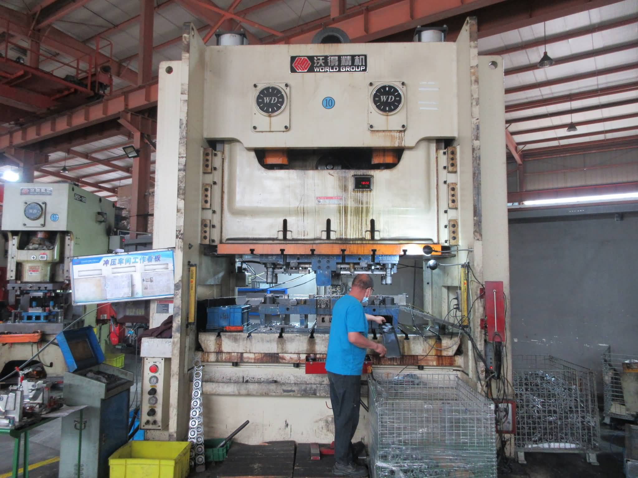
Ang stamping ay isang mataas na bilis, prosesong cold forming na nag-uugnay ng patag na sheet metal sa mga tiyak na bahagi gamit ang custom dies at isang presa—na nagbibigay ng pagkakaunlad, mataas na throughput, at mababang gastos bawat bahagi sa malaking saklaw.
Sa mismong pokus nito, ang depinisyon ng stamping ay nakatuon sa pagbabago ng sheet metal sa mga functional na komponente nang walang paggamit ng init. Sa halip, gumagamit ang stamping ng napakalaking puwersa mula sa isang presa upang ipush o iritsa ang metal sa nais na hugis. Ito minsan ay tinatawag manufacturing stamping , at ito ang pinakapundasyon ng masalimuot na produksyon sa walang bilang na industriya—mula sa mga kotse hanggang sa mga kagamitang pangkusina.
Kahulugan na Maibabahagi ng mga Inhinyero at Mamimili
Inilalarawan ng mga inhinyero ang stamping bilang isang prosesong porma sa malamig kung saan inilalagay ang patag na metal na sheet sa loob ng isang die at binubuo gamit ang isang press. Madalas nakikita ng mga mamimili ang stamping bilang isang maaasahang paraan upang makagawa ng malalaking dami ng mga bahaging may tumpak na sukat nang mabilis at ekonomikal. Ang proseso ay batay sa mga pamantayan at paulit-ulit, na nagpapadali sa pagtukoy at pagkuha nito.
Mga Pangunahing Operasyon sa Stamping
Tila kumplikado? Isipin ang isang metal na sheet na unti-unting nababago habang ito'y gumagalaw sa loob ng isang press. Narito ang ilan sa mga pinakakaraniwang operasyon sa stamping na iyong mararanasan:
- Pagpuputol : Pagputol ng isang patag na hugis (blank) mula sa mas malaking sheet o coil, na nagbibigay-daan sa susunod na pagbubuo.
- Pagbuho : Pagbubutas o paggawa ng mga puwang sa metal na sheet.
- Pagbubuo : Pagyuko o paghubog sa metal upang makabuo ng mga kurba, palara, o anggulo.
- Pagdrawing : Pag-angat sa metal papasok sa isang die cavity upang makalikha ng mas malalim, hugis-tasa na anyo.
- Flanging : Pagbuburol sa gilid ng metal upang lumikha ng isang gilid o labi.
- Paggawa ng barya : Paggamit ng mataas na presyon upang i-imprint ang mga detalyadong disenyo o patigasin ang ibabaw, kadalasang ginagamit para sa mga logo o eksaktong katangian.
- Pag-embos : Paglikha ng mga nakataas o nalalagom na disenyo para sa tekstura o pagkakakilanlan.
Ang bawat hakbang ay maaaring isagawa nang mag-isa o nang sabay-sabay, depende sa kumplikado ng bahagi. Halimbawa, ang progresibong die ay maaaring pagsamahin ang ilang operasyon sa isang pagkakataon upang mapataas ang kahusayan.
Kung Saan Nakalagay ang Stamping sa Halo ng Produksyon
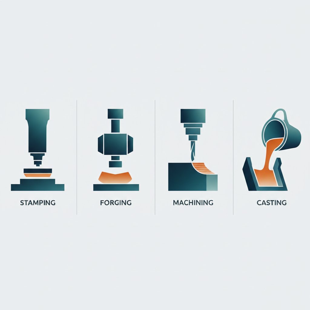
Kung gayon, kung saan nakalagay ang stamping kumpara sa iba pang proseso ng pagtrato sa metal? Ang stamping ay isang subset ng pagbuo ng sheet metal, na nakatuon lalo na sa produksyon na may mataas na dami at bilis gamit ang mga die at press. Ang mag-press ay ang makina na nagbibigay ng puwersa, samantalang pag-stamp ay ang proseso na nagbibigay-hugis sa metal. Ang iba pang pamamaraan ng pagbuo, tulad ng forging o machining, ay maaaring mas mainam para sa mas mababang dami o mas makapal na bahagi ngunit kadalasang hindi kayang tularan ang bilis at murang gastos ng stamping para sa manipis hanggang katamtamang kapal ng sheet metal.
Mga Benepisyo at Limitasyon sa Isang Sulyap
- Mahusay para sa mataas na produksyon kung saan napakahalaga ng pagkakapare-pareho ng mga bahagi.
- Nagbibigay ng mahigpit na toleransya at kumplikadong hugis na may pinakakaunting basura.
- Pinakamainam para sa patag o manipis na 3D na bahagi; ang malalim o makapal na bahagi ay maaaring nangangailangan ng ibang proseso.
- Ma-uulit at masusukat—perpekto para sa mga sektor ng automotive, appliance, electronics, at hardware.
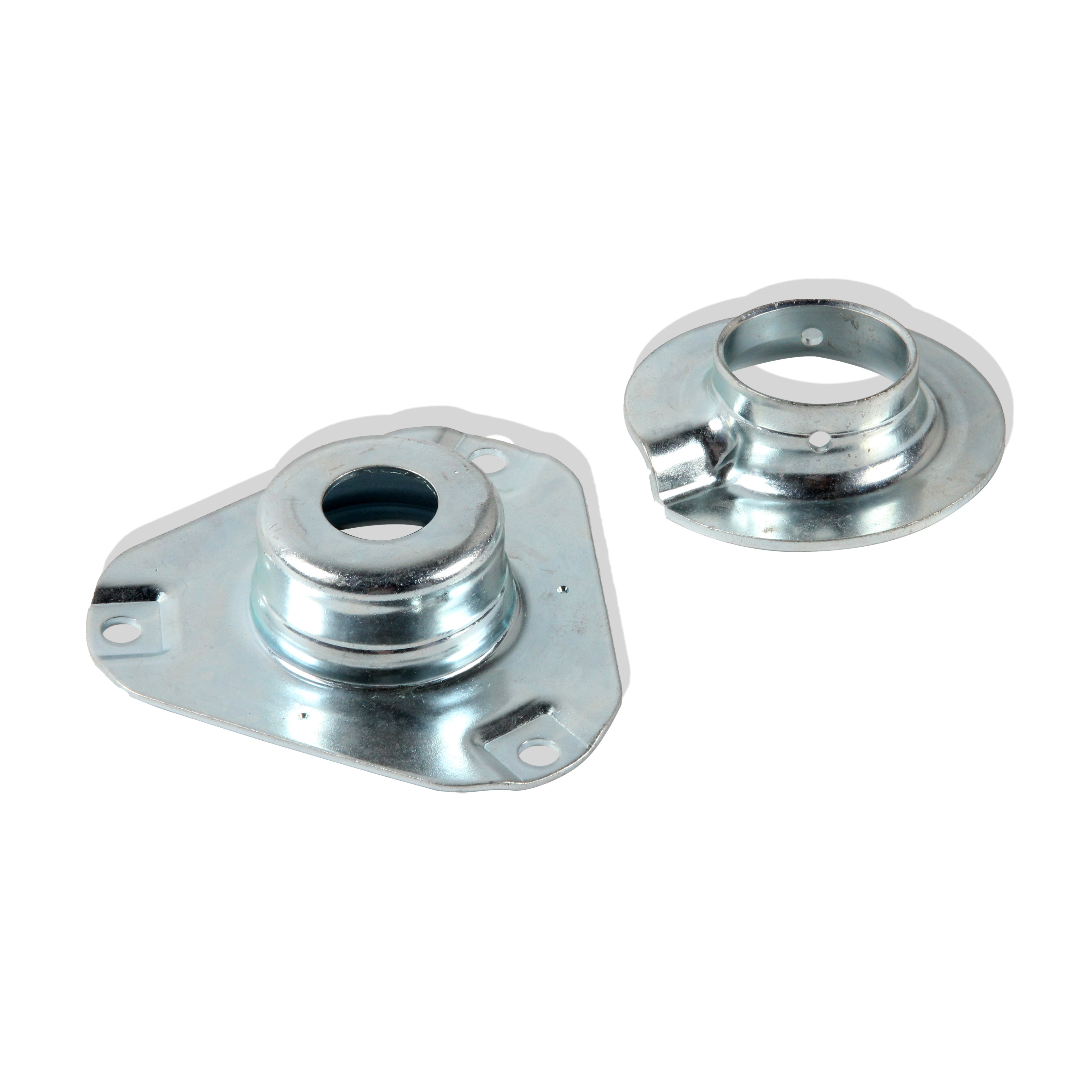
Karaniwang aplikasyon ay kinabibilangan ng mga panel ng katawan ng sasakyan, panlabas na bahagi ng appliance, mga takip ng electronic device, at hardware tulad ng mga bracket o clip. Mapapansin mo na ano ang metal stamping talagang nauuwi sa epektibong pagbabago ng sheet metal sa eksaktong, functional na mga bahagi na nagpapatakbo sa modernong mga produkto [Wikipedia] .
Sa maikli, ang kahulugan ng stamping sa pagmamanupaktura ay tungkol sa paggamit ng cold forming at pasadyang dies upang makamit ang bilis, kawastuhan, at pagtitipid sa gastos—ginagawa itong pangunahing solusyon para sa masusing produksyon kung saan ang kalidad at kahusayan ay hindi pwedeng ikompromiso.

Paano Naging Natapos na Bahagi ang Sheet Metal
Nagtanong ka na ba kung paano isang simpleng roll ng metal sheet ang nagiging isang de-kalidad na sangkap na handa nang gamitin sa iyong kotse, appliance, o electronic device? Ang sagot ay matatagpuan sa puso ng isang stamping plant—kung saan ang isang nakasunod-sunod na hanay ng mga makina at proseso ay nagtutulungan upang magbigay ng mataas na bilis at mataas na produksyon. Halika't tayo'y maglakad sa pamamagitan ng kung ano ang nangyayari sa loob ng isang karaniwang press line, at kung paano pinipili ang tamang stamping machinery para sa gawain.
Mula sa Coil Hanggang sa Mga Sangkap
Ang paglalakbay ay nagsisimula sa isang coil ng hilaw na metal. Isipin mo ang isang malaking roll na unti-unting binubunot at ipinapasok nang maayos sa linya. Narito kung paano gumagana ang bawat yugto:
- Decoiler : Binubunot ang metal coil at tinitiyak ang maayos at walang tensyon na pagpasok nito sa linya.
- Straightener : Pinapantay ang metal, tinatanggal ang coil set at mga alon upang maging pare-pareho ang itsura.
- Pamimilo : Sinusundan nang eksakto ang sheet papasok sa stamping press sa takdang agwat, tugma sa siklo ng die.
- Die set : Ang mga pasadyang die ay nakakabit sa press; anyo, pinuputol, o binubuong muli ang metal habang gumagawa ang press.
- Outfeed/Conveyor inililipat ang mga natapos na sheet metal pressings at kalawang mula sa press para sa karagdagang proseso o pag-recycle.
Ang bawat piraso ng metal ay dumaan sa sekwenyang ito, kung saan ang mga sensor at kontrol ay nagmomonitor sa bawat yugto para sa kalidad at kahusayan.
Mga Uri ng Press at Mga Kaso ng Paggamit
Pumili ng tama stamping press ay mahalaga. Ang tatlong pangunahing uri—mekanikal, hydrauliko, at servo—ay may kanya-kanyang natatanging kalakasan sa production line:
- Mga mekanikal na preno mabilis, mahusay, at perpekto para sa mataas na dami ng produksyon. Ginagamit nila ang flywheel upang maghatid ng puwersa—mainam para sa mga gawain kung saan pinakamahalaga ang bilis at pag-uulit.
- Mga hydraulic presses nag-aalok ng tiyak na kontrol at mataas na puwersa, na gumagawa nito bilang perpektong opsyon para sa malalim na drawing o pagbuo ng mas makapal na materyales. Mas mabagal man ito, ngunit outstanding sa kakayahang umangkop at pagiging pare-pareho.
- Servo Presses pinakabagong henerasyon, na pinagsasama ang bilis at katumpakan. Ang programmable motion ay nagbibigay-daan sa custom na stroke profile, pagtitipid sa enerhiya, at mabilis na pagbabago ng setup—perpekto para sa mga kumplikadong o nagbabagong pangangailangan sa produksyon.
| Uri ng Press | Kontrol ng galaw | Kahusayan sa Enerhiya | Kakayahang Umangkop sa Setup | Mga Tipikal na Aplikasyon |
|---|---|---|---|---|
| Makinikal | Nakapirming, mabilis na siklo | Mataas (para sa simpleng mga bahagi) | Mababa | Malaking dami, simpleng hugis |
| Haydroliko | Baryable, mabagal/kontrolado | Moderado | Katamtaman | Malalim na pagguhit, mas makapal na bahagi |
| Servo | Programadong, tumpak | Mataas (pang-agni ng enerhiya) | Mataas | Kumplikado, baryable na gawain |
Halimbawa, kung kailangan mo ng libo-libong magkaparehong suporta bawat oras, ang mekanikal na metal stamping press ay karaniwang pinakamainam. Para sa masalimuot na mga bahay o bahagi na may baryable na kapal, ang hydraulic o servo press ay nagbibigay ng kinakailangang kontrol.
Sunod-sunod: Ang Linya ng Stamping Press sa Pagkilos
- Handaing ng materyales : Pumili at ihanda ang tamang metal coil para sa iyong bahagi.
- Lubrication : Ilapat upang mabawasan ang pananakip at pagsusuot ng die.
- Strip Layout : Isaplano kung paano nakakaupo ang mga bahagi sa strip para sa pinakamahusay na paggamit ng materyal.
- Mga Operasyon ng Die : Ang progresibong o transfer dies ay nagpapatakbo ng blanking, piercing, forming, at iba pa habang gumagalaw ang strip sa bawat estasyon.
- Mga sensor sa loob ng die : Bantayan ang posisyon, puwersa, at pagkakaroon ng bahagi para sa kaligtasan at kalidad.
- Paglabas ng Bahagi : Ang mga natapos na bahagi ay hiwalay at ililipat sa outfeed.
- Pamamahala ng Scrap : Ang mga sobrang piraso ay kinokolekta para i-recycle o itapon.
Ang workflow na ito ay nagsisiguro na ang bawat stamped part ay sumusunod sa mahigpit na mga tukoy, na may real-time na mga pagbabago dahil sa modernong stamping machinery at kontrol.
Mga Pamilya ng Die at Mga Diskarte sa Linya
Walang isang laki na akma sa lahat ng gawain para sa die. Narito kung paano pipili ang mga tagagawa:
- Progressive dies : Patuloy na gumagalaw ang metal strip sa maraming estasyon, kung saan bawat isa ay nagtatanghal ng iba't ibang operasyon. Mahusay para sa mataas na dami, maliit hanggang katamtamang mga bahagi.
- Transfer dies : Ang mga indibidwal na blanks ay naililipat mula sa isang estasyon patungo sa iba pa. Pinakamainam para sa mas malalaking, mas kumplikadong bahagi o kapag kinakailangan ang malalim na paghubog.
- Mga linyang die : Mga naka-standalone na die, bawat isa ay nasa hiwalay na presa, na ginagamit para sa napakalaking bahagi o kapag kailangan ng kakayahang umangkop sa mga operasyon.
Kaligtasan, Sensor, at Kalidad
Ang mga modernong press line ay nilagyan ng mga safety interlock at sensor para sa proteksyon ng die upang maiwasan ang aksidente at madiskubre ang mga isyu bago ito makaapekto sa produksyon. Ang mga sistema ng pangangalaga ay hindi lamang nagpoprotekta sa kagamitan kundi pinabubuti rin ang kalidad ng bahagi at pinalalawig ang buhay ng die. Sa pagsasama ng mga elementong ito, ang mga kasalukuyang sheet metal pressings ay nagbibigay ng walang kamatayang konsistensya at maaasahan.
Susunod, tatalakayin natin kung paano nakaaapekto ang pagpili ng materyales sa proseso ng stamping at kung ano ang kailangan mong malaman upang mapili ang tamang metal para sa iyong susunod na proyekto.
Pagpili ng Materyales para sa Sheet Forming
Kapag nakaharap ka sa isang bagong disenyo ng bahagi, ang tanong ay hindi lamang kung ano ang pag-stamp sa pagmamanupaktura—kundi pati na rin kung aling metal para sa pag-stamp ang magbubunga ng pinakamahusay na resulta. Ang tamang pagpili ng materyal ay maaaring magtagumpay o mapabigo ang gastos, kalidad, at kakayahang mapagawa ng iyong proyekto. Alamin natin kung paano iba't ibang metal ang kumikilos sa pag-stamp, kung ano ang maaaring mali, at kung paano gumawa ng mas matalinong pagpili para sa susunod mong produksyon.
Mga Pamilya ng Materyales at Kanilang Pag-uugali
Isipin mo na parang pumipili ka sa menu ng mga metal: bawat isa ay may sariling lakas, kakaibang katangian, at angkop na aplikasyon. Narito kung paano nagsisilbi ang mga karaniwang pamilya sa mga materyales para sa pag-stamp ng metal:
- Mababang Carbon na Bakal : Ang pangunahing gamit sa maraming trabaho sa pag-stamp—madaling i-form, murang gastos, at madaling ipasa sa karamihan ng mga hugis. Mainam para sa mga bracket, panel, at pangkalahatang takip.
- HSLA at Advanced High-Strength Steels (AHSS) : Nagbibigay ng mas mataas na lakas na may mas magaang timbang, kaya sila ay popular sa mga bahagi ng sasakyan at istruktura. Mas mahirap hubugin at mas madaling tumalsik o bumalik ang hugis, kaya napakahalaga ng kontrol sa proseso.
- Stainless steels : Nag-aalok ng paglaban sa korosyon at mataas na pagganap sa matinding temperatura. Karaniwan ang austenitic na grado sa pag-stamp ng stainless steel, ngunit mabilis itong lumambot at maaaring pumutok kung hindi maingat na pinamamahalaan.
- Aluminio Alpaks : Magaan, lumalaban sa korosyon, at palaging ginagamit sa automotive at electronics. Ang proseso ng pag-stamp ng aluminum ay nangangailangan ng maingat na pamamahala sa pagbabalik ng hugis at maaaring mangailangan ng espesyal na lubricant upang maiwasan ang galling.
Iba pang mga espesyal na materyales—tulad ng tanso, brass, o titanium—ay ginagamit din kapag kailangan ang conductivity, kakayahang hubugin, o lakas na may magaang timbang.
Mga Paraan ng Pagkabigo at Mga Solusyon
Napakukomplikado ba? Maaari—ngunit ang pag-alam kung ano ang maaaring mali ay nakakatulong upang maiwasan ang mga mahahalagang problema. Narito ang ilan sa pinakakaraniwang depekto sa pag-stamp at kung ano ang maaari mong gawin dito:
- Pagsira/Pagputok : Nangyayari ito kapag ang metal ay lubhang na-stretch, lalo na sa malalim na hugis o matitigas na taluktok. Ang mga bakal na may mas mataas na lakas at manipis na gauge ay mas madaling maapektuhan.
- Pagkakaroon ng mga sugat : Nagkakalat ang sobrang material, lalo na sa mga sulok o flanges. Ang mga malambot na metal at maliit na hugis ay nasa mas mataas na panganib.
- Galling : Nakakapit ang metal sa mga surface ng die, karaniwan sa paggawa ng stainless at aluminum. Nakakatulong ang lubrication at die coatings.
- Springback : Bumabalik ang metal sa dating posisyon matapos ang pagbuo, na nagdudulot ng hindi tumpak na sukat. Karaniwang sanhi ang mga alloy ng aluminum at AHSS.
Ihahambing natin ang mga ugaling ito nang magkaside para sa mas malinaw na pagtingin:
| Pamilya ng Materyales | Karaniwang Saklaw ng Kapal | Mga Tala sa Formability | Karaniwang Mga Modes ng Pagkakamali | Mga Iminungkahing Paraan upang Maiwasan |
|---|---|---|---|---|
| Low-carbon steel | 0.5–3.0 mm | Mahusay na ductility; madaling i-bend at i-draw | Paggulong (maliit na hugis), minor springback | Karaniwang lubrication; katamtamang radii; restrike kung kinakailangan |
| HSLA/AHSS | 0.7–2.0 mm | Matibay na lakas; mas maliit na saklaw ng kakayahang pabaguhin | Pagkabahagi, pagbalik sa dating hugis, pagbitak sa gilid | Mas malalaking radius, lubricantong may mataas na pagganap, draw beads, overbending |
| Stainless steel | 0.32.5 mm | Mabilis na pagtigas habang ginagawa; katamtamang kakayahang pabaguhin | Pagbitak, pagkagat, pagbabalik sa dating hugis | Pinakintab na dies, de-kalidad na lubricants, anneal kung matindi |
| Aluminum Alloy | 0.5–3.0 mm | Malambot, magaan; madaling bumalik sa dating hugis | Pagkagat, pagkurap, mataas na pagbabalik sa dating hugis | Espesyal na lubricants, mas malalaking bend radius, overbend, restrike |
Mga Tiyak at Pamantayan ng Tagapagtustos
Kapag pinapaligiran mo ang iyong mga pagpipilian, huwag kalimutang suriin ang mga teknikal na detalye. Karamihan sa mga tagapagtustos ay tumutukoy sa mga metal gamit ang mga kilalang pamantayan tulad ng ASTM (para sa Hilagang Amerika) o EN (para sa Europa). Kasama rito ang mga mahahalagang katangian:
- Lakas sa Pagkabigat : Ang puwersa na kailangan upang magsimula ang permanenteng pagbabago ng hugis.
- Elongation : Gaano kahaba ang maaaring lumuwang ng metal bago putulin—mas mataas ang mas mainam para sa malalim na pagguhit.
- Hugis ng ibabaw : Nakakaapekto sa itsura at kakayahan sa pagpipinta; ang magaspang na tapusin ay maaaring dagdagan ang pagsusuot ng die.
Kung gumagawa ka kasama ang OEM na mga plano, palaging i-cross-check ang mga tawag sa materyales sa datasheet ng iyong tagapagtustos upang matiyak ang tugma sa iyong proseso ng pag-stamp. Halimbawa, ang mga kinakailangan sa proseso ng pag-stamp ng aluminum ay maaaring tumukoy sa tiyak na haluang metal at temper para sa pinakamainam na kakayahan sa paghubog at paglaban sa korosyon.
Mga Praktikal na Heuristiko sa Pagpili
- Magsimula sa pinakamababang grado ng lakas na sapat na nakakatugon sa mga pasanin ng iyong bahagi. Binabawasan nito ang springback at ginagawang mas madali ang paghuhubog.
- I-verify ang iyong napili gamit ang mga kupon para sa pagsubok o maliit na simulasyon bago magpasya sa buong produksyon.
- Makipagtulungan nang malapit sa iyong tagapagkaloob ng materyales o kasosyo sa pag-stamp—maaari nilang irekomenda ang pinakamahusay na metal para sa metal stamping batay sa hugis, dami, at pangangailangan sa pagganap.
- Para sa aluminium stamping, gumamit ng mas malalaking radius ng pagbabaluktot at de-kalidad na lubricant upang bawasan ang panganib ng galling at springback.
Sa pamamagitan ng pag-unawa kung paano tumutugon ang bawat materyales sa stamping—at sa maagang pagpaplano para sa mga karaniwang hadlang—mas mapapadali mo ang produksyon, mas kaunting depekto, at mas mahusay na kita. Susunod, titingnan natin kung paano ang matalinong disenyo para sa kakayahang mabuo ay mas lalo pang nababawasan ang panganib at kumplikado sa iyong mga proyekto sa stamping.
Disenyo para sa Kakayahang Mabuo at Toleransya
Nagtanong ka na ba kung bakit mas madali at mas mura i-produce ang ilang disenyo kumpara sa iba kapag nakita mo ang isang stamped na bahagi? Ang sagot ay nasa matalino pandisenyo ng pag-stamp mga pagpipilian na nagpapahalaga sa mga limitasyon at kalakasan ng proseso ng paggawa sa pamamagitan ng stamping. Kung ang iyong layunin ay ang eksaktong stamping ng maliit na mga bracket o matibay na disenyo ng sheet metal stamping para sa mga kahon, ang pagsunod sa mga patunay na DFM na alituntunin ay makakatipid sa iyo sa mga problema, pagbabago, at hindi kinakailangang gastos.
Pinakamaliit na Radii at Clearance
Naririnig na komplikado? Hindi naman dapat ganoon. Isipin mo ang pagbubuwig mo ng isang paperclip laban sa isang bakal na bar—mas matigas ang materyal, mas malaki ang posibilidad na mabasag kung subukang ipaikot nang matalim. Ang parehong prinsipyo ang gumagana sa stamping:
- Para sa malambot, duktil na materyales (tulad ng maamong asero): Panatilihing hindi bababa sa kapal ng materyales ang loob na radius ng pagbuwig.
- Para sa hindi gaanong duktil, mas matitigas na materyales (tulad ng 6061-T6 aluminum): Gamitin ang pinakamaliit na bend radius na 4× ng kapal o higit pa upang maiwasan ang pagkabasag [Gabay sa Five Flute DFM] .
- Tandaan: Mas matigas o mas malakas ang metal, mas malaki ang kailangang radius para sa malinis at walang bitak na pagbuwig.
Pantay na mahalaga ang clearance. Ang mga katangian tulad ng mga baluktot, butas, at puwang ay nangangailangan ng sapat na espasyo sa isa't isa at sa mga gilid upang maiwasan ang pagkakaubos o pagkabali sa panahon ng pagbuo. Halimbawa, magdagdag ng bend reliefs (mga maliit na puptan sa gilid ng mga baluktot) upang bawasan ang stress concentration at maiwasan ang mga bitak—layuning magkaroon ng lapad ng relief na hindi bababa sa kalahati ng kapal ng materyal.
Pagitan ng Feature at Disenyo ng Butas
Napansin mo na ba ang isang stamped part na may deformed na butas o tumambok na gilid? Karaniwan itong senyales na napakalapit ang feature sa isang baluktot o gilid. Narito ang ilang praktikal na alituntunin para gabayan ang iyong disenyo:
- Bilis ng Buhol : Para sa ductile na metal, gawing hindi bababa sa 1.2× ang kapal ng materyal; para sa mas matitigas na alloy, gamitin ang 2× ang kapal.
- Pagitan ng butas at gilid : Ilagay ang mga butas nang hindi bababa sa 1.5–2× ang kapal ng materyal mula sa mga gilid.
- Pagitan ng Butas at Butas : Panatilihing hindi bababa sa 2× ang kapal ang pagitan ng mga butas upang maiwasan ang pagkabago.
- Distansya mula sa mga baluktot : Ilagay ang mga butas o puwang nang hindi bababa sa 2.5× ang kapal kasama ang bend radius mula sa mga baluktot.
- Lapad ng Slot : Gawing hindi bababa sa 1.5× ang kapal ang lapad ng mga puwang para sa malinis na punching.
- Haba ng Emboss : Limitahan ang embossing sa 3× na kapal ng materyal upang maiwasan ang pagkabasag.
Kapag may duda, kumonsulta sa iyong stamping partner o suriin ang OEM DFM manual para sa mga rekomendasyon na nakabatay sa materyal.
GD&T para sa mga Stamped na Feature
Gaano kalapot ang dapat na tolerances? Bagaman presisong pagpapasigla maaari itong maisagawa, masyadong mahigpit na tolerances ay maaaring tumaas ang gastos at kumplikado. Narito kung paano itakda ang realistiko mong inaasahan:
- Gamitin ang profile, posisyon, at flatness na tolerances na sumasalamin sa proseso ng pagbuo—iwasan ang paghiling ng CMM-level na presisyon maliban kung talagang kinakailangan.
- Gumamit ng functional datums—mga reference na feature na madaling suriin at tugma sa mga pangangailangan sa pag-assembly.
- Ipaalam nang malinaw sa mga drawing ang mga critical-to-function na feature; ang mga secondary na feature ay maaaring magkaroon ng mas maluwag na tolerances upang makatipid sa gastos.
Halimbawa, ang mga pierced hole ay maaaring magkaroon ng bahagyang taper o burr, habang ang mga formed flange ay maaaring magkaroon ng maliit na pagbabago sa anggulo—normal lang ito sa stamping manufacturing process at dapat ito ay masalamin sa iyong GD&T callouts.
Mga Checklist para sa Tagumpay ng DFM
Gusto mo bang maiwasan ang mga mahal na pagkakamali? Narito ang isang mabilis na tseklis para sa susunod mong pagsusuri ng disenyo sa pagpoporma ng sheet metal:
| DFM Rule | Kung Bakit Mahalaga |
|---|---|
| Gamitin ang inirerekomendang minimum na bend radii para sa bawat materyal | Pinipigilan ang pagkabasag o pagkakapit sa mga taluktok |
| Panatilihing wasto ang espasyo sa pagitan ng mga butas, puwang, at iba pang detalye | Binabawasan ang pagbaluktad at nagagarantiya ng malinis na pag-punch |
| Magdagdag ng bend reliefs kung saan nakatagpo ang mga taluktok sa mga gilid | Kinokontrol ang tensyon at pinipigilan ang mga bitak |
| I-limita ang lalim ng emboss sa 3× ang kapal | Naiiwasan ang pagkabigo ng materyal habang ito ay binubuo |
| Magtakda ng realistiko na GD&T tolerances | Nagbabalanse sa kalidad at kakayahang magawa nang may kontrol sa gastos |
Ang ilang mga katangian ay maaaring palakasin ang die—and ang iyong proyekto—nang higit sa kailangan. Gamitin ang listahang ito upang mapansin ang mga babala:
- Napakaliit na pagbubutas malapit sa mga baluktok
- Malalim na drawing na may mahigpit na mga radius
- Mga logo o teksto na kinukumpuni sa materyales na mataas ang lakas
- Mga katangian na nangangailangan ng maramihang hakbang sa paghubog sa isang solong die
Upang mapamahalaan ang springback, isaalang-alang ang overbending, dagdagan ang restrike station, at gamitin ang process control—tumatulong ito upang matiyak na ang mga stamped parts ay sumusunod sa spec, kahit sa mga hamong materyales o hugis.
Sa pamamagitan ng pagsunod sa mga DFM na alituntunin at masusing pakikipagtulungan sa iyong stamping supplier, gagawa ka ng mga stamping halimbawa na matibay, ekonomiko, at handa na para sa produksyon. Susunod, tatalakayin natin kung paano nakaaapekto ang tooling at pangangalaga ng die sa resulta ng iyong stamping manufacturing process.
Pamamahala sa Tooling at Buhay ng Die
Nagtanong ka na ba kung bakit ang ilang mga die para sa stamping ay tumatagal ng maraming taon, samantalang ang iba ay parang mabilis masira pagkatapos lamang ng ilang production run? Ang sagot ay nasa maingat na pagpili, pangangalaga, at pagsubaybay sa iyong mga kagamitan. Kung ikaw man ay nagtatakda ng custom metal stamping dies para sa bagong proyekto o nagsusuri ng mga isyu sa iyong stamping plant, mahalaga ang pag-unawa sa mga uri ng die, mekanismo ng pagsusuot, at pinakamahusay na pamamaraan sa pangangalaga upang matiyak ang pare-parehong kalidad at operasyon nang walang agwat.
Mga Uri ng Die at Aplikasyon
Hindi pantay-pantay ang lahat ng die. Ang tamang pagpili ay nakadepende sa hugis ng bahagi, dami, at mga operasyong kailangan. Narito ang maikling paglalarawan sa mga pangunahing uri ng stamping die na ginagamit sa die stamping:
- Blanking Dies : Pinuputol ang patag na mga hugis (blanks) mula sa sheet metal, na siyang nagsisilbing panimulang punto para sa karagdagang paghubog.
- Compound dies : Isinasagawa ang maramihang operasyon (tulad ng pagputol at pagbubukod) sa isang solong stroke, mainam para sa bahagi na may katamtamang kumplikado at katamtamang dami.
- Progressive dies : Tampok ang serye ng mga istasyon sa loob ng isang die set, kung saan ang bawat isa ay gumaganap ng tiyak na operasyon habang tumataas ang strip—perpekto para sa mataas na dami at kumplikadong mga bahagi.
- Transfer dies : Ilipat ang mga indibidwal na blanks sa pagitan ng mga istasyon para sa sunud-sunod na operasyon; pinakamainam para sa malalaki o magkakaunting bahagi na nangangailangan ng malalim na draw o maramihang hakbang sa pagbuo.
Ang bawat uri ng die ay nag-aalok ng natatanging mga benepisyo. Halimbawa, ang progressive dies ay mahusay sa paggawa ng pare-parehong bahagi nang mabilis, samantalang ang compound dies ay pumuputol sa oras ng setup para sa mas maliit na produksyon. Ang pagpili ng tamang teknolohiya ng die ay isang mahalagang hakbang upang ma-optimize ang iyong sheet metal stamping dies sa gastos at pagganap.
Mga Mekanismo ng Pagsusuot at Mga Ugat na Sanhi
Isipin mo ang iyong die bilang isang tool na may presisyong laging inaatake—bawat press cycle ay dala ng friction, pressure, at init. Sa paglipas ng panahon, ito ay humahantong sa pagsusuot at, kung hindi kontrolado, sa mapaminsalang downtime. Kasama sa pinakakaraniwang mekanismo ng pagsusuot sa steel stamping dies ang:
- Abrasive wear : Hinuhukot ng matitigas na partikulo sa sheet o ibabaw ng tool ang materyal, na nagdudulot ng pagkawala ng presisyon.
- Pang-adherens na Pagsusuot/Pagkakagat : Napapasa ang metal mula sa workpiece sa die, na nagdudulot ng pag-akyat ng surface at magaspang na tapusin.
- Chipping : Mga maliit na piraso ang napapaloob sa gilid ng die, madalas sa mga sulok o mataas na puntos ng stress.
- Mga depormasyon ng plastik : Permanenteng bumabaluktot ang surface o mga katangian ng die sa ilalim ng labis na karga.
Ano ang nagdudulot ng mga isyung ito? Kasama rito ang mga salik tulad ng:
- Pagpili ng die steel at paggamot nito gamit ang init
- Mga clearance sa pagitan ng punch at die
- Tapusin ang surface at mga patong
- Kalidad at paraan ng paglalagay ng lubricant
Hayaan nating paghiwalayin ang pinakakaraniwang mga mekanismo ng pagsusuot, ang kanilang mga sintomas, at kung paano ito maiiwasan:
| Mekanismo ng Pagsusuot | Tanda | Mga Malamang na Pananampalataya | Mga Hakbang sa Pag-iwas |
|---|---|---|---|
| Abrasive wear | Pagkawala ng talas ng gilid, magaspang na ibabaw ng putol | Matitigas na partikulo sa sheet, hindi sapat na kahigpitan | Gamitin ang mataas na kahigpit na tool steel, pakanin ang die, mag-apply ng mga coating |
| Pang-adherens na Pagsusuot/Pagkakagat | Paglipat ng materyal, pagtubo, pagguhit sa ibabaw | Mahinang pangpapadulas, hindi tugma ang pagkabit ng die at sheet | Mag-apply ng de-kalidad na mga lubricant, gamitin ang TiN/TiAlN coatings, isabay ang uri ng die steel sa materyal |
| Chipping | Panghihina ng gilid, nagkakalag lag na mga sulok | Mataas na stress, matutulis na sulok, mahinang tibay ng die | Pataasin ang mga radius ng gilid, pumili ng mas matibay na tool steel, at tamang tempering |
| Mga depormasyon ng plastik | Mga permanenteng deformed na bahagi, pagkawala ng hugis | Labis na karga, mahinang hardness ng die | I-optimize ang materyal ng die at pagpoproseso ng init, iwasan ang sobrang karga |
Ang mga pag-unlad sa mga coating (tulad ng PVD-applied TiAlN o CrN) at powder metallurgy tool steels ay malaki ang nagpabuti sa performance ng die, lalo na kapag binubuo ang advanced high-strength steels. Mahalaga ang tamang surface finish (Ra < 0.2 μm) at pagpapatigas ng substrate bago ilagay ang coating upang mapahaba ang buhay ng tool [AHSS Insights] .
Dalas ng Pagpapanatili na Nagpoprotekta sa Buhay ng Die
Nagtatanong kung gaano kadalas dapat suriin o serbisyohan ang iyong mga die? Walang isang-sukat-para-lahat na sagot, ngunit ang isang sistematikong programa sa pagpapanatili ay ang pinakamahusay mong depensa laban sa mga sirang kagamitan at basura. Narito ang isang natuklasang paraan:
- Pagsusuri Bago Gamitin : Suriin para sa nakikitang wear, bitak, o misalignment. Linisin at lagyan ng lubricant kung kinakailangan.
- Pagsusuri sa Unang Piraso patakbuhin ang sample na bahagi at suriin para sa katumpakan ng sukat, mga gilid na may tumbok, o mga depekto sa ibabaw.
- Pantuloy na Pagsubaybay Habang Gumagawa regular na suriin ang kalidad ng bahagi at makinig para sa di-karaniwang ingay na maaaring magpahiwatig ng problema sa die.
- Pagsusuri Matapos ang Produksyon linisin ang mga die, suriin para sa pananakot o pagkakasira, at i-document ang anumang isyu para sa kaukulang aksyon.
- Pagpapatalas/Pagpapanumbalik i-iskedyul batay sa dami ng bahagi, katigasan ng materyal, at obserbasyong pananakot—maaaring kailanganin ng ilang die ang pagpapatalas pagkatapos ng sampung libo-libong ikot, habang ang iba ay mas tumatagal nang may tamang pangangalaga.
- Pagpapalit ng Bahagi palitan ang mga nasirang springs, pins, o inserts kung kinakailangan upang mapanatili ang presisyon ng die.
Mahalaga ang regular na paglilinis, paglalagyan ng langis, at pagsusuri sa pagkaka-align. Gamitin ang angkop na shims upang mapanatili ang katumpakan ng die set at bawasan ang misalignment. Ang paggamit ng predictive maintenance techniques—tulad ng vibration analysis o thermal imaging—ay makatutulong upang mahuli ang mga problema bago ito magdulot ng downtime.
Matalinong Estratehiya para sa Mas Matagal na Buhay ng Die
- Mga sensor sa loob ng die : Bantayan ang puwersa, pag-alis ng bahagi, at pagsusuot ng kagamitan sa totoong oras—upang matulungan na maiwasan ang malalaking kabiguan.
- Pagkakalign ng Die Set : Iregular na i-calibrate at i-align ang mga die upang maiwasan ang hindi pare-parehong paglo-load at maagang pagsusuot.
- Estratehiya sa Mga Spare : Panatilihing nandoon ang mga mahahalagang spare component upang minumin ang downtime kapag may hindi inaasahang kabiguan.
Sa huli, ang tibay ng iyong mga sheet metal stamping dies ay nakadepende sa matalinong disenyo, tamang pagpili ng materyales, at disiplinadong rutina ng pagpapanatili. Sa pamamagitan ng pagbibigay-pansin sa mga salik na ito, mapapataas mo ang uptime, babawasan ang basura, at masisiguro na ang iyong die stamping operations ay magbibigay ng pare-pareho at dekalidad na resulta.
Sa susunod na seksyon, tatalakayin natin kung paano lalong napoprotektahan ng matibay na quality control at mga checkpoint sa inspeksyon ang iyong mga naka-stamp na bahagi at produksyon throughput.
Quality Control at Mga Checkpoint sa Inspeksyon
Kapag gumagawa ka ng mga libo o kahit milyon-milyong stamped na bahagi, paano mo masisiguro na ang bawat piraso ay sumusunod sa pamantayan? Ang kalidad ng stamping ay hindi lamang tungkol sa pagtukoy ng maruruming bahagi sa huli; ito ay tungkol sa pagbuo ng katiyakan sa bawat hakbang ng proseso ng metal stamping. Alamin natin kung paano pinamamahalaan ang mga depekto at kung ano ang hitsura ng matibay na inspeksyon sa isang modernong operasyon ng stamping.
Mga Uri ng Depekto na Dapat Bantayan
Isipin mo na nagpapatakbo ka ng isang batch ng mga stamped na metal na bahagi at natuklasan ang mga isyu lamang pagkatapos ng pag-assembly—nakakainis, di ba? Sa pamamagitan ng pag-unawa sa karaniwang uri ng mga depekto, maaari kang mag-setup ng mga kontrol upang mahuli ang mga ito nang maaga. Narito ang mga pangunahing isyung dapat bantayan:
- Burrs : Matalas, hindi gustong gilid mula sa mga operasyon sa pagputol. Ang labis na burr ay maaaring makahadlang sa pagkakabuklod o kaligtasan.
- Rollover : Mga bilog o deformed na gilid mula sa punching; maaaring makaapekto sa pag-assembly o sealing.
- Fractured Edges : Mga bitak o punit sa mga lugar na pinutol o nabuo, kadalasang dahil sa labis na t tensyon o mahinang kalagayan ng die.
- Thinning : Ang materyal ay nagiging masyadong manipis sa mga hinugot o naunat na bahagi, na nagdudulot ng panganib na mabigo ang bahagi.
- Pagkakaroon ng mga sugat : Mga alon o mga kulubot sa sheet, karaniwan dahil sa sobrang materyal o hindi tamang parameter sa pagbuo.
- Springback : Bumabalik ang hugis ng bahagi pagkatapos ito mabuo, na nagdudulot ng hindi tumpak na sukat.
- Mga Depekto sa Surface : Mga gasgas, dampa, o mantsa dulot ng maruming die, debris, o hindi sapat na pangpahid.
Ang bawat isa sa mga ito ay nakakaapekto sa tungkulin o hitsura ng mga naka-stamp na metal na bahagi, kaya't napakahalaga ang pag-iwas at pagtuklas nito.
Plano ng Inspeksyon Ayon sa Yugto
Ang kontrol sa kalidad sa proseso ng sheet metal ay isang nakakahihigit na gawain, na may mga pagsusuri sa bawat pangunahing hakbang:
- Pag-verify sa Paparating na Materyales : I-kumpirma ang uri ng alloy, kapal, at kalidad ng surface bago magsimula ang produksyon.
- Pagsusuri sa unang artikulo : Sukatin ang isang sample na bahagi mula sa paunang takbo upang i-verify ang lahat ng katangian laban sa disenyo.
- Pagsusuri Habang Nagda-dadaloy : Periodikong pagsusuri habang gumagawa upang madiskubre ang paglihis o pagsusuot ng tool bago ito magdulot ng basura.
- Huling inspeksyon : Suriin ang mga natapos na bahagi para sa kritikal na sukat, tapusin ang ibabaw, at mga pamantayan sa pagganap bago ipadala.
| Tampok | Paraan ng pagsusuri | Halimbawa ng Pamantayan sa Pagtanggap |
|---|---|---|
| Taas ng Burr | Tagasubok ng gilid na magaspang, pansining pagsusuri | Loob ng tinukoy na pinakamataas (hal., walang matutulis na gilid) |
| Posisyon ng Butas | Pang-ukol, CMM, optikal na sistema | Loob ng posisyonal na pasensya (ayon sa drawing) |
| Anggulo ng Flange | Protractor, CMM | Loob ng pasensya ng anggulo (hal., ±1°) |
| Hugis ng ibabaw | Pansining, optical comparator | Walang malalim na gasgas, mantsa, o dampa |
| Kapal ng Materyal (Mga Hinugis na Bahagi) | Micrometer, ultrasonic gauge | Hindi mas mababa sa pinakamaliit na takdang kapal |
Mga Kasangkapan sa Pagsukat at Pinakamahusay na Kasanayan
Anong mga kasangkapan ang nakatutulong upang matiyak ang kalidad ng stamping? Narito ang isang praktikal na listahan:
- Mga calipers at micrometer para sa mabilisang pagsusuri ng sukat
- Coordinate Measuring Machines (CMM) para sa mga kumplikadong hugis
- Optical vision systems o comparators para sa non-contact, mataas na presisyong pagsukat
- Mga edge burr tester para sa taas at talas ng burr
- Pasadyang mga gauge para sa go/no-go na pagsusuri sa mahahalagang katangian
Upang matiyak na maaasahan ang iyong mga pagsukat, isagawa ang gage R&R (Repeatability and Reproducibility) na pag-aaral—nito ay nagpapatibay na pare-pareho ang proseso ng inspeksyon at hindi nakadepende sa operator.
Ang paggamit ng statistical process control (SPC) sa mga kritikal na sukat at dokumentasyon ng mga pampawi-aksyon kapag may lumilitaw na kalakaran ay mahalaga para sa pang-matagalang kakayahan at mas kaunting sorpresa sa produksyon.
Mga Balangkas sa Kalidad at Patuloy na Pagpapabuti
Ang nangungunang mga planta ng stamping ay umaasa sa mga internasyonal na kinikilalang balangkas sa kalidad tulad ng ISO 9001 at IATF 16949. Ang mga pamantayan na ito ay nangangailangan ng dokumentadong mga pamamaraan, patuloy na pagsubaybay sa proseso, at dedikasyon sa patuloy na pagpapabuti. Sa pamamagitan ng pagsunod sa mga balangkas na ito, tinitiyak mo na ang bawat batch ng mga stamped metal parts ay pare-pareho na nakakatugon sa inaasahan ng customer at regulasyon.
Sa pamamagitan ng pagsasama ng mga checkpoint sa inspeksyon at mga kasangkapan sa kalidad, hindi mo lamang mababawasan ang mga depekto kundi bubuo rin ng tiwala sa mga customer na umaasa sa iyong mga napatampang bahagi para sa mahahalagang aplikasyon. Susunod, titingnan natin kung paano makatutulong ang mga kalkulasyon sa inhinyero upang magplano para sa maaasahan at paulit-ulit na resulta sa produksyon.

Mga Kalkulasyong Pang-inhinyero na Maaari Mong Kopyahin
Kapag nagpaplano ka ng isang proyektong pagpapatampang, kailangan mo ng higit pa sa simpleng haka-haka—kailangan mo ng mga numero na mapagkakatiwalaan. Kung ikaw ay naglalaki ng isang metal stamping press machine o bumubuo ng patag na piraso para sa isang kumplikadong bahagi, ilang pangunahing kalkulasyon ang magpapanatili sa proseso mo nang maayos. Mukhang kumplikado? Hatiin natin ito nang sunud-sunod gamit ang mga praktikal na formula at mga relatable na halimbawa.
Paghuhula ng Lakas ng Presa
Gaano karaming puwersa ang kailangang ipaabot ng iyong metal stamp press upang masukat ang toneladang kinakailangan? Ang pagkababa sa pagtatantiya ng tonelada ay maaaring makasira sa kagamitan o makagawa ng mga depektibong bahagi, samantalang ang sobrang laki ay nagdaragdag ng hindi kinakailangang gastos. Narito kung paano mo mahuhulaan ang kinakailangang tonelada para sa karaniwang operasyon ng pagpapatampang:
- Blanking & Piercing: Gumamit ng formula: Palapalibot × Kapal ng Materyal × Lakas ng Shear = Kailangang Tonnage .
- Pagpapaliko: Ang tonnage ay nakadepende sa uri ng materyal, kapal, haba ng pagbabaluktot, at bukas na dies—ginagamit ang mga koepisyente mula sa handbook para sa eksaktong mga halaga.
- Paggagawa: Gamitin ang pinakamataas na lakas ng tensile imbes na lakas ng shear para sa malalim na drawing.
Mga Pangunahing Pormula:
Blanking/Piercing:
Tonnage = Sukat ng Gilid × Kapal × Shear Strength
Paggagawa:
Tonnage = Palapalibot × Kapal × Pinakamataas na Lakas ng Tensile
Pagpapaliko:
Tonnage = (Koepisyente) × Haba ng Pagbabaluktot × Kapal 2/ Buka ng Die
(Kumuha ng lakas ng shear, lakas ng tensile, at mga K-factor mula sa datasheet ng iyong materyales o pinagkakatiwalaang mga handbook.)
Huwag kalimutang isama ang dagdag na karga para sa blank holder pads, stripper springs, o cams. Para sa progresibong mga die, i-total ang mga karga sa bawat estasyon upang makuha ang kabuuang kailangang tonnage. Para sa mas detalyadong gabay, tingnan ang Gabay ng Tagapagfabricate sa Pagkalkula ng Stamping .
Pag-unlad ng Blangko at Pahintulot sa Pagbabaluktot
Nakapagsimula ka na ba ng kahon mula sa patag na sheet at nakatapos na may maling sukat pagkatapos bumaluktot? Dito napapasok ang pagkalkula ng blank stamping. Kapag binabaluktot mo ang metal, lumalawig at lumiliit ang materyal—kaya kailangang i-adjust ang iyong patag na blangko upang makamit ang tamang huling hugis. Narito kung paano:
- Pahintulot sa Pagbabaluktot (Bend Allowance o BA): Haba ng arko kasama ang neutral axis ng pagbubulok. Pormula: BA = Angle × (π/180) × (Bend Radius + K-Factor × Thickness)
- Bawas sa Pagbubulok (Bend Deduction o BD): Halaga na inaalis sa kabuuang haba ng flange upang makuha ang patag na haba. Pormula: BD = 2 × (Bend Radius + Thickness) × tan(Angle/2) – BA
Gamitin ang mga halagang ito upang kalkulahin ang pasimulang patag na haba para sa iyong bahagi. Ang K-Factor (karaniwang nasa 0.3 hanggang 0.5 para sa karamihan ng mga metal) ay isinasaisip ang paglipat ng neutral axis habang bumabagal. Laging kunin ang K-Factor at mga halaga ng bend radius mula sa iyong supplier ng materyales o datasheet para sa katumpakan.
Upang kompensahan ang springback (pagbalik ng metal sa orihinal na hugis matapos ito hubugin), isaalang-alang ang overbending o pagdaragdag ng restrike station. Lalo itong mahalaga kapag gumagamit ng mataas na lakas na asero o mga haluang metal na aluminum sa blank stamping.
Cycle Time at Throughput
Gaano kabilis ang maaaring takbo ng iyong proseso sa production stamping? Ang cycle time at throughput ay nakadepende sa:
- Strokes Per Minute (SPM): Kung ilang beses bumibilis ang press bawat minuto.
- Bilang ng mga estasyon: Ang bawat operasyon sa isang progressive die ay nagdadagdag ng isang station.
- Oras ng Transfer: Oras na kinakailangan upang ilipat ang strip o blank mula sa isang station patungo sa iba pa.
Throughput = SPM × Bilang ng Bahagi bawat Stroke. Halimbawa, kung ang iyong metal stamping press machine ay tumatakbo sa 60 SPM at gumagawa ng isang bahagi bawat stroke, gagawa ito ng 3,600 bahagi kada oras. Maaaring mas mababa ang aktuwal na bilis dahil sa paghawak ng materyales, kumplikadong die, o mga hakbang sa pagsusuri nang paisa-isa. Mahalaga ang pagmomonitor sa cycle time bilang sukatan ng pagganap—tingnan ang press metrics ng Aomate Machinery para sa karagdagang impormasyon tungkol sa pag-optimize ng throughput.
Nasolusyunang Halimbawa: Pagtukoy ng Sukat ng Press at Paghahambing ng Flat Blank
-
Blanking Tonnage:
- Paligid ng bahagi: [Ilagay ang halaga, hal., 200 mm]
- Kapal ng Materyal: [Ilagay ang halaga, hal. 1.0 mm]
- Katibayan sa Shear: [Ilagay ang halaga mula sa datasheet, hal. 400 MPa]
- I-convert ang mga yunit kung kinakailangan (hal. mm sa in, MPa sa psi).
- Ilagay ang mga halaga sa: Tonnage = Sukat ng Gilid × Kapal × Shear Strength
-
Bend Allowance:
- Anggulo ng pagbend: [Ilagay ang halaga, hal. 90°]
- Bend Radius: [Ilagay ang halaga, hal. 2 mm]
- K-Factor: [Ilagay ang halaga, hal. 0.4]
- Kapal ng Materyal: [Ilagay ang halaga, hal. 1.0 mm]
- Ilagay ang mga halaga sa: BA = Angle × (π/180) × (Bend Radius + K-Factor × Thickness)
-
Pagkalkula ng Habang Flat:
- Magdagdag ng haba ng flange, ibawas ang bend deductions para sa bawat pagyuko.
- Tumukoy sa CAD software o gumamit ng manu-manong kalkulasyon tulad ng nakasaad sa itaas.
-
Pagpili ng Press:
- Magdagdag ng safety margin (karaniwang 20–30%) sa kinalkulang tonelada.
- Suriin ang sukat ng press bed at mga kinakailangan sa enerhiya.
- Itakda ang die protection upang maiwasan ang overload at matiyak ang ligtas na operasyon.
-
Oras ng siklo:
- Tukuyin ang SPM batay sa kumplikadong anyo ng bahagi at materyal.
- Kalkulahin ang output kada oras: SPM × bilang ng bahagi kada stroke × 60.
Sa pamamagitan ng pagsunod sa mga hakbang na ito, masisiguro mong ligtas at epektibo ang iyong blank stamping at production stamping processes. Laging basihin ang pinakabagong datos ng materyal at i-ayos ang mga kalkulasyon para sa mga tunay na salik tulad ng die wear o maintenance ng press. Ang ganitong kahigpitan sa inhinyero ang nagtatakda sa isang mataas na pagganap na stamping operation.
Susunod, alamin natin kung paano makatutulong ang cost drivers at ROI modeling upang mapabuti ang iyong stamping program para sa pangmatagalang tagumpay.
Paano Mapapabuti ang Iyong Metal Pressings
Nagulat ka na ba kung bakit ang dalawang mukhang magkatulad na stamped na bahagi ay may malaking pagkakaiba sa gastos? O kung paano ang isang matalinong pagbabago sa disenyo o estratehiya sa produksyon ay maaaring baguhin ang isang mahal na bahagi sa isang matipid na resulta? Kung ikaw man ay buyer, inhinyero, o production planner, ang pag-unawa sa tunay na mga salik ng gastos sa production metal stamping ay susi upang mapataas ang iyong ROI at lubos na mapakinabangan ang iyong metal pressing services.
Ano ang Nagtutulak sa Gastos Bawat Bahagi
Hatiin natin ang mga pangunahing salik sa gastos ng mga stamped metal components. Isipin mo ang kabuuang gastos ng bahagi bilang isang pie chart—ang bawat hiwa ay kumakatawan sa isang salik na maaari mong impluwensyahan:
- Amortisasyon ng Kagamitan : Ang paunang puhunan sa dies at tooling ay nahahati sa kabuuang bilang ng mga bahaging ginawa. Sa mataas na volume metal stamping, ang gastos bawat bahagi ay malaki ang pagbaba habang tumataas ang dami.
- Run Rates : Mas mabilis na press speeds at epektibong setups ay nangangahulugan ng higit na bahagi bawat oras, na nagpapababa sa labor at overhead bawat yunit.
- Paggamit ng Materyales : Kung gaano kahusay ang paggamit sa metal strip o coil. Ang mabuting nesting at layout ng strip ay nagpapakunti sa kalawang, na direktang nagbabawas sa gastos.
- Tasa ng Basura : Mas mataas na kalawang ang ibig sabihin ay higit pang nasayang na materyales at mas mataas na gastos. Ang pag-optimize sa oryentasyon ng bahagi at disenyo ng die ay makatutulong.
- Pampadulas at Mga Gamit Na Nasasayang : Ang mga pampadulas, panlinis, at mga kasangkapan na nasasayang ay pumipila, lalo na sa mataas na dami ng produksyon.
- Mga Pagpapalit : Ang oras na ginugol sa paghahanda sa pagitan ng mga trabaho ay nakakain sa produktibidad. Ang mga estratehiya tulad ng quick-change tooling at SMED (Single-Minute Exchange of Die) ay nagbabawas sa oras ng hindi paggawa.
- Mga Sekundaryong Operasyon : Ang mga proseso tulad ng deburring, plating, o pag-assembly ay nagdaragdag ng gastos sa paggawa at materyales. Ang pagsasama nito sa loob ng die o pagbawas sa pangangailangan ay nakakatipid ng pera.
Ayon sa mga eksperto sa industriya, ang pagpili ng materyales at pamumuhunan sa tooling ang dalawang pinakamalaking driver ng gastos, ngunit mahalaga rin ang kumplikadong disenyo, dami ng produksyon, at kahusayan sa operasyon.
| Driver ng Gastos | Epekto sa Kabuuang Gastos | Mga Sangkap Para sa Pag-optimize |
|---|---|---|
| Amortisasyon ng Kagamitan | Mataas para sa mababa ang dami, mababa para sa mataas ang dami | Pataasin ang laki ng batch, standardisahin ang mga dies, i-share ang tooling sa iba't ibang bahagi |
| Paggamit ng Materyales | Direktang nakakaapekto sa gastos sa materyales | Pabutihin ang nesting, bawasan ang lapad ng web, i-optimize ang orientasyon ng bahagi |
| Tasa ng Basura | Nagdudulot ng mas mataas na gastos sa basura | Baguhin ang disenyo para sa mas mahusay na layout ng strip, gamitin ang simulation upang mahulaan ang scrap |
| Run Rates | Nakakaapekto sa gastos sa trabaho at overhead bawat bahagi | I-automate ang paghawak, gamitin ang mataas na bilis na presa, minumehan ang idle time |
| Mga Pagpapalit | Ang idle time ay binabawasan ang throughput | Ipapatupad ang SMED, modular na mga dies, i-schedule nang magkasama ang magkatulad na trabaho |
| Mga Sekundaryong Operasyon | Nagdadagdag ng gawain, pinalalawak ang lead time | Isama sa loob ng die ang tapping, deburring, o pag-aasemble kung maaari |
Mga Breakpoint at Estratehiya sa Dami
Kailan makatuwiran na mag-invest sa pasadyang metal stamping services, at kailan dapat mong tingnan ang mga alternatibo? Madalas, ang sagot ay nakadepende sa dami ng produksyon:
- Mataas na dami ng metal stamping : Kung gumagawa ka ng libo-libo o milyon-milyong bahagi, ang progressive dies at automation ang nagtutulak sa pinakamababang gastos bawat bahagi. Ang mga gastos sa tooling ay nahahati-hati sa malalaking produksyon, at ang kahusayan ng proseso ay pinakamaksimal.
- Mababa hanggang katamtamang dami : Para sa mas maliit na batch, maaaring hindi nababayaran ang mataas na paunang gastos sa tooling. Ang soft tooling, modular dies, o kahit ang laser-blank kasama ang form approach ay maaaring mag-alok ng kakayahang umangkop nang walang malaking pamumuhunan.
- Kumplikasyon ng Disenyo : Mas murang i-stamp ang simpleng, simetriko na bahagi; ang mga kumplikadong hugis na may mahigpit na tolerances o maraming feature ay nagpapataas ng gastos.
Madalas na sulit na makipagtulungan sa iyong tagagawa ng metal na bahagi nang maaga sa proseso ng disenyo—maaari nilang imungkahi ang mga pagbabago upang mas maging madaling i-stamp at mas ekonomikal ang iyong bahagi.
Mga Salik sa Pagkuwota at Lead Time
Ano ang kasama sa isang kuwota para sa mga metal stamping na sangkap? Ang ilang mga variable ang nakakaapekto sa gastos at oras ng paghahatid:
- Kumplikadong Anyo ng Bahagi : Mas maraming tampok, mas masiglang tolerances, at kumplikadong geometriya ang nangangailangan ng mas advanced na tooling at mas mahabang oras ng setup.
- Bilang ng Die Station : Ang bawat karagdagang operasyon ay nagdaragdag ng oras sa engineering, paggawa, at pagsisiyasat.
- Mga Pagsubok sa Tryout : Maaaring kailanganin ang prototyping at pagsusuri upang mapatunayan ang disenyo at tooling bago magsimula ang produksyon.
- Kakayahang Magamit ng Materyal : Ang mga eksotikong haluang metal o di-karaniwang gauge ay maaaring magpataas ng lead time kung hindi agad na nasa stock.
- Kapasidad ng Tagapagtustos : Maaaring mas mahaba ang lead time sa mga abalang tindahan, lalo na para sa mataas na dami o mga rush order.
Para sa pinakatumpak na quote, ibahagi ang iyong taunang volume, mga drawing ng bahagi, at mga kinakailangan sa pagganap sa iyong stamping partner. Ang maagang pakikipag-ugnayan ay nakakatulong upang matukoy ang potensyal na gastos o mga panganib sa lead time bago pa man ito maging isyu.
ROI Playbook: Pagmo-modelo ng Iyong Stamping Program
Isipin mo na binabalanse mo ang dalawang opsyon: isang mababang-gastong die para sa maikling produksyon, o isang premium progressive die para sa patuloy na produksyon. Paano ka magdedesisyon? Narito ang isang simpleng paraan para i-modelo ang iyong ROI:
- Tantiyahin ang Kabuuang Gastos sa Tooling : Isama ang gawa ng die, setup, at validation.
- Kalkulahin ang Gastos Bawat Bahagi : Dagdagan ang materyales, labor, overhead, at amortized tooling na hinati sa taunang volume.
- Isama ang Scrap Rate : Gamitin ang realistiko na mga pagpapalagay batay sa hugis ng bahagi at nakaraang mga produksyon.
- Magsagawa ng Sensitivity Analysis : I-model ang iba't ibang volume at scrap rate upang makita kung paano nagbabago ang gastos bawat bahagi.
- Isama ang Secondary Operations : Huwag kalimutan isali ang mga gastos para sa finishing, plating, o assembly.
Ang tamang pamamaraan ay nakadepende sa iyong partikular na pangangailangan, ngunit sa pamamagitan ng pag-unawa sa mga salik na ito, mas handa ka nang gumawa ng desisyon batay sa datos at mapataas ang halaga ng iyong production metal stamping program.
Susunod, titingnan natin kung paano ang mga pag-unlad sa teknolohiya ng presa at automation ang hugis ng hinaharap ng metal pressings at ano ang ibig sabihin nito para sa iyong susunod na proyekto.
Modernong Presa at Automation na Hugis ng Resulta
Kapag isinipat mo ang isang stamping plant, ba ay mayroon kang isipin ng mga hanay ng malalakas na pres at mga manggagawa na nagmamadali para hindi mahuli? Ang katotohanan sa ngayon ay mas napakaraming advanced. Ang pinakabagong teknolohiya sa pag-stamp ay pinagsama ang mga programmable press, robotics, at matalinong sistema ng data upang magbigay ng kalidad, bilis, at pagtitipid sa gastos na hindi pa isinasip kahit isang dekada lamang ang nakalilipas. Tingnan natin kung paano binabago ng mga inobasyong ito sa metal stamping machine ang larangan para sa mga tagagawa at inhinyero.
Mga Benepisyo ng Servo Press
Isipin mo na maari mong i-tune ang bawat galaw ng iyong metal stamper machine para sa pinakamataas na eksaktitud. Ito ang pangako ng servo press teknolohiya. Hindi tulad ng tradisyonal na mekanikal na press—na gumagana sa nakapirming siklo—ang servo press ay gumagamit ng mga programmable motor upang kontrolin ang bilis, posisyon, at puwersa ng slide sa bawat punto ng stroke. Ang kakayahang umangkop na ito ay nagbibigay-daan sa:
- Pinaunlad na Formability: Bagalan o itigil ang stroke sa mga mahahalagang punto para sa mas mahusay na daloy ng materyal, na binabawasan ang panganib ng pagputok o pagkurap.
- Bawasan ang Snap-Through: Mas malambot at kontroladong galaw sa ilalim ng stroke ay nagpapakonti ng shock load, na nagpoprotekta sa die at sa press.
- Mas Mahusay na Kontrol sa Restrike Operations: Kakayahang tumigil o ulitin ang galaw para sa malinaw na gilid at masikip na tolerances.
- Kahusayan ng Enerhiya: Ginagamit lamang ang kuryente kung kinakailangan, kaya nababawasan ang gastos sa enerhiya kumpara sa mekanikal na presa na patuloy na gumagana.
- Mabilis na Pagpapalit: I-program at i-rekord ang iba't ibang stroke profile para sa iba't ibang trabaho, na nagpapabilis sa pag-setup—perpekto para sa mataas na hain, mababa hanggang katamtaman ang dami ng produksyon.
Ang mga katangiang ito ang nagiging dahilan kung bakit nangunguna ang servo-driven metal stamping machine para sa mga komplikadong bahagi na may mataas na presisyon o kapag ginagamit ang advanced na materyales. Gayunpaman, nangangailangan ito ng mas mataas na paunang puhunan at mas bihasang operator kumpara sa mekanikal na presa.
High-Speed Stamping at Coil Automation
Ang bilis ay nananatiling hari sa maraming operasyon ng pag-stamp. Ang mga mataas na bilis na preno, na may kasamang awtomatikong straightener, feeder, at sistema ng pagpapalit ng die, ay kayang gumawa ng libo-libong bahagi bawat oras. Narito kung paano pinapataas ng modernong kagamitan sa pag-stamp ng sheet metal ang produksyon:
- Mga Straightener at Feeder: Nagagarantiya na perpektong patag at tumpak na nakaposisyon ang materyales papasok sa die sa bawat ikot, binabawasan ang mga pagkakabara at basura.
- Awtomatikong Pagpapalit ng Die: Ang mga robotic system ang nagpapalit ng mabibigat na die sa ilang minuto lamang, hindi oras, upang patuloy na gumagalaw ang linya ng produksyon at bawasan ang downtime.
- Pinagsamang Paglalagay ng Lubrikante: Ang mga awtomatikong sistema ang nagdadala ng eksaktong dami ng lubricant, pinalalawig ang buhay ng tool at pinapabuti ang kalidad ng bahagi.
Ang mga pag-unlad na ito ay nangangahulugan na ang makabagong stamping machine para sa metal ay kayang humawak ng mas maraming trabaho, gamit ang mas kaunting manu-manong pakikialam at mas mataas na pagkakapare-pareho—na partikular na mahalaga sa mga industriya tulad ng electronics at automotive kung saan ang bilis at katiyakan ay hindi pwedeng ikompromiso.
Robotics at In-Line Inspeksyon
Ano naman ang tungkol sa salik ng tao? Ang mga modernong linya ng pag-stamp ay nakadepende na nang mas malaki sa robotics at pagsusuri sa loob ng linya upang mapataas ang kalidad at kakayahang umangkop. Narito ang iyong makikita:
- Mga Robot sa Paglilipat: Inililipat ang mga bahagi sa pagitan ng mga istasyon o preno gamit ang perpektong pag-uulit, na nagpapababa sa gastos sa paggawa at pagkakamali ng tao.
- Sistemang Machine Vision: Ang mga kamera at software na pinapagana ng AI ay nagsusuri sa mga bahagi nang real time, na nahuhuli ang mga depekto bago pa man ito iwan ng linya.
- Mga Sensor sa Loob ng Die: Nagbabantay sa puwersa, posisyon, at pagkakaroon ng bahagi, na nagtutrigger ng mga alerto o awtomatikong pag-shutdown kung may natuklasang problema.
Sa pamamagitan ng pagsasama ng mga sistemang ito, nababawasan ng mga tagagawa ang pagkakaiba-iba, napapabilis ang pagsusuri ng ugat ng problema, at ginagarantiya na ang bawat bahagi ay sumusunod sa mahigpit na mga pangangailangan—hindi mahalaga kung gaano kabilis ang takbo ng linya.
Paghahambing ng Mechanical at Servo Presses
| Tampok | Mekanikal na press | Servo Press |
|---|---|---|
| Kontrol ng galaw | Nakapirming siklo na mataas ang bilis | Programmable, may iba't-ibang bilis at posisyon |
| Paggamit ng Enerhiya | Tumatakbo nang patuloy, mas mataas ang baselines na konsumo | On-demand, mas mababang kabuuang paggamit ng enerhiya |
| Epekto sa Habambuhay ng Kasangkapan | Mas mataas na shock loads, mas maraming wear sa paglipas ng panahon | Mas maayos na galaw, pinalalawig ang buhay ng die/kagamitan |
| Kakayahang Umangkop sa Setup | Manu-manong pag-aadjust, mas mabagal na pagpapalit | Imbakan ng programa, mabilis na pagpapalit |
| Pinakamahusay para sa | Mataas na dami, simpleng mga bahagi | Kumplikadong, nagbabagong trabaho at advanced na materyales |
Industry 4.0: Smart Manufacturing para sa Stamping
Isipin mo ang iyong metal stamp machine na hindi lamang gumagawa ng mga bahagi, kundi nagsasabi pa kung kailangan na serbisyuhan—o kaya ay hulaan ang posibleng pagkabigo sa hinaharap. Iyon ang kapangyarihan ng Industry 4.0 sa stamping technology. Kasalukuyang kasama sa nangungunang kagamitan sa sheet metal stamping:
- Pagsusuri sa kalagayan para sa lahat ng pangunahing bahagi ng press at die
- Mapaghuhulaang pagpapanatili gamit ang datos ng vibration, temperatura, at lubricant
- Pag-log ng datos para sa Statistical Process Control (SPC) at pagsubaybay sa kalidad
- Automatikong mga alerto para sa mga paglihis, pagsusuot ng tool, o mga isyu sa materyales
Tinutulungan ka ng mga digital na kasangkapan na mas maaga makakita ng mga problema, mapabuti ang produksyon, at mabawasan ang downtime—nagiging mas matalino at mapagkumpitensya ang iyong stamping operation.
Epekto sa Disenyo at Kakayahang Pagmamanupaktura
Kung gayon, paano nakaaapekto ang lahat ng mga pag-unlad na ito sa disenyo ng iyong bahagi? Gamit ang programmable presses at in-line inspeksyon, maaari mong:
- Gumawa ng mas masikip na mga baluktot o mas kumplikadong mga katangian nang hindi kinakailangang mag-risk ng depekto
- Bawasan ang bilang ng mga forming station na kailangan para sa mga detalyadong bahagi
- Ipagmaikli ang development cycle gamit ang digital twins at simulation tools
Ang resulta: mas mabilis na paglulunsad, mas kaunting mga pagkabigla, at ang tiwala na palawigin ang mga hangganan sa iyong mga disenyo ng stamped part. Habang patuloy na umuunlad ang teknolohiya ng stamping, inaasahan ang mas malaking integrasyon ng AI, additive manufacturing, at mga sustainable na kasanayan—na nagbubukas daan para sa mas matalino, mas berde, at mas fleksibleng produksyon.
Susunod, ihahambing natin ang stamping sa iba pang proseso ng pagmamanupaktura, upang matulungan kang magpasya kung kailan pipiliin ang stamping—at kung kailan ang mga alternatibo tulad ng CNC, casting, o forging ay mas angkop na pagpipilian.
Pagpili ng Stamping Kumpara sa Iba Pang Proseso
Kailan Angkop ang Stamping
Nagtanong ka na ba kung ang pag-stamp ay ang pinakamainam para sa iyong susunod na proyekto, o kung may iba pang proseso na magbubunga ng mas mahusay na resulta? Isipin mo naman na ilulunsad mo ang isang bagong automotive bracket, consumer electronics housing, o appliance panel. Kung ang iyong bahagi ay gawa sa manipis o katamtamang kapal na sheet metal, may pare-parehong kapal, at kailangang gawin nang malaking dami na may mataas na pagkakapareho, ang pag-stamp at pagpindot sa isang dedikadong stamping plant ay mahirap matalo. Narito kung kailan nagliliwanag ang pag-stamp:
- Mga kumplikadong 2D o manipang 3D hugis, tulad ng mga bracket, takip, o enclosures
- Malaking dami ng produksyon—mula sa libo-libo hanggang milyon-milyong bahagi
- Pare-pareho at maigsing tolerances sa buong malalaking batch
- Manipis hanggang katamtamang gauge na metal (bakal, aluminum, tanso)
- Automotive metal stamping para sa body panel at structural reinforcements
- Husay sa gastos dahil sa mabilis na cycle times at minimum na basura
Ang pag-stamp ay nagsisilbing likas na batayan ng maraming proseso sa pagmamanupaktura, lalo na sa mga industriya kung saan mahalaga ang pagkakapare-pareho at bilis ng produksyon. Gayunpaman, hindi ito ang tanging opsyon—lalo na para sa mga bahagi na may natatanging pangangailangan.
Mga Alternatibo at Kasamang Proseso
Ano kung makapal ang iyong bahagi, kritikal sa kaligtasan, o nangangailangan ng sobrang lakas? O marahil napakakomplikado ng hugis nito para sa isang stamping die, o gumagawa ka lamang ng maliit na dami ng produksyon? Dito papasok ang mga alternatibo tulad ng forging, machining, casting, at iba pa. Pag-aralan natin ang mga pangunahing opsyon, na nagsisimula sa pagtutuon sa forging para sa automotive at aplikasyon na nangangailangan ng mataas na lakas:
- Shaoyi Automotive Forging Parts : Kapag kailangan mo ng hindi matatawarang lakas, paglaban sa pagod, at tibay—tulad sa mga bahagi ng suspensyon, steering knuckles, o drivetrain—ang precision hot forging ang nangungunang pamantayan. Ang aming mga bahagi para sa automotive ay ginawa sa isang pasilidad na sertipikado sa IATF 16949, na nagagarantiya ng pinakamataas na kalidad. Nag-aalok kami ng kompletong solusyon mula sa prototyping hanggang sa masalimuot na produksyon, kasama ang disenyo ng die sa loob ng kumpanya at pandaigdigang pagpapadala na pinagkakatiwalaan ng higit sa 30 automotive brand. Ang forging ay perpekto kung ang stamping ay mangangailangan ng masyadong maraming forming station, kung may panganib ang springback, o kung kritikal ang direksyonal na grain flow para sa kaligtasan.
- Cnc machining : Pinakamainam para sa maliit hanggang katamtamang dami, makapal o solidong bahagi, at kapag kailangan ang napakatiyak na toleransya o kumplikadong 3D na katangian. Mas mabagal at mas mahal ang machining bawat piraso kumpara sa stamping ngunit nagbibigay ito ng pinakamataas na kakayahang umangkop.
- Paghuhulma (Die, Buhangin, Investment) : Angkop para sa mga kumplikadong, makapal na pader na bahagi o kapag kailangan ang panloob na kuwarto. Karaniwan ang paghuhulma para sa mga bloke ng engine o katawan ng bomba, ngunit maaaring magdulot ito ng butas at nangangailangan ng maingat na kontrol sa proseso.
- Pagpapasok ng Porma (Metal/Plastik) : Perpekto para sa maliliit, detalyadong bahagi sa mataas na dami—lalo na kapag prayoridad ang kumplikadong disenyo o pagbawas ng timbang. Ginagamit ang metal injection molding (MIM) para sa napakaliit, tumpak na sangkap.
- Paggupot gamit ang Laser/Plasma na may Pagpaporma : Mahusay para sa prototype, pasadyang isahan, o mababang produksyon kung saan hindi nababayaran ang gastos sa die para sa pagtutumbok. Ang mga pamamarang ito ay nag-aalok ng mabilis na paggawa at kakayahang umangkop sa disenyo, kasama ang pangalawang pagpaporma kung kinakailangan.
- Pagpapaligid na Pagpaporma at Pagpilit : Pinipili para sa mahahaba, pare-pareho ang cross-section (tulad ng riles o frame) at mataas na throughput, lalo na sa industriya ng konstruksyon at mga appliance.
| Proseso | Kumplikadong Anyo ng Bahagi | Makakamit na Toleransiya | Karaniwang Saklaw ng Dami | Mga Limitasyon ng Materyales | Oras ng paghahanda |
|---|---|---|---|---|---|
| Mga Parte ng Pagkakalubog para sa Automotibo | Makapal, kritikal sa seguridad, mataas ang lakas; simpleng hanggang katamtamang kumplikado | Katamtaman hanggang masikip (matapos ang machining) | Mula mababa hanggang mataas; nakakasukat batay sa pangangailangan ng proyekto | Mga bakal, mga haluang metal na nangangailangan ng direksyonal na binhi | Katamtaman (kailangan ang disenyo ng die) |
| Pag-stamp | Pantay, manipis na 3D, kumplikadong 2.5D | Masikip; pinakamahusay para sa mga paulit-ulit na katangian | Mataas (libo-libo hanggang milyon-milyon) | Mga sheet metal (bakal, aluminum, tanso) | Maikli hanggang katamtaman (oras ng paggawa ng tooling) |
| Cnc machining | Napakakumplikado, 3D, nagbabago | Napakasikip (posibleng mikron) | Mababa hanggang Medyo | Praktikal na lahat ng mga metal at plastik | Maikli (kung may stock pa) |
| PAGMOMOLDO | Makapal, kumplikado, panloob na mga kuwarto | Katamtaman (ang post-processing ay nakapagpapabuti) | Mababa hanggang mataas | Malawak na hanay; pinakamahusay para sa mga natunaw na metal | Katamtaman hanggang mahaba (oras ng paggawa ng mold) |
| Injection Molding (MIM/Plastic) | Maliit, detalyado, kumplikado | Masikip (lalo na para sa maliit na bahagi) | Mataas | Pulbos na metal o plastik | Katamtaman (kailangan ang tooling) |
| Laser/Plasma + Pagpaporma | Simple hanggang katamtaman; prototype/pasadya | Katamtaman (nakadepende sa pagpaporma) | Napakababa hanggang mababa | Mga metal na nakakahon | Napakaliit (walang kagamitan) |
| Pagpaporma sa pamamagitan ng rolyo/Ekstrusyon | Mahaba, pare-pareho ang hugis | Masikip (para sa mga profile) | Katamtaman hanggang mataas | Aluminum, bakal, tanso na haluang metal | Katamtaman (kailangan ang tooling) |
Paano Magpasya
- Pumili ng forging kung kailangan mo ng makapal, mataas ang lakas, o mga bahaging kritikal sa kaligtasan kung saan hindi pwedeng ikompromiso ang direksyon ng daloy ng grano at resistensya sa impact—lalo na sa automotive, mabigat na makinarya, o aerospace.
- Pumili ng stamping para sa manipis hanggang medium gauge na mga bahagi, mataas na volume ng produksyon, at kapag ang pag-uulit at mababa ang gastos bawat bahagi ang nangungunang priyoridad—tulad ng automotive stamping para sa body panel o electronic housings.
- Pumili ng CNC machining para sa prototype, makapal o solidong bahagi, o kapag ang hugis at toleransya ay lampas sa limitasyon ng stamping.
- Isaisip ang casting para sa komplikadong disenyo, makapal ang pader, o mga hugis na may butas kung kailangan ang mga detalye sa loob.
- Isipin ang injection molding (MIM/plastic) para sa maliit ngunit mataas ang presisyon na mga bahagi na gagawin sa napakataas na dami.
- Gamitin ang laser/plasma cutting na may forming para sa custom na trabaho, maikling produksyon, o kapag kailangan ang pinakamataas na kalayaan sa disenyo nang walang imbestment sa tooling.
Sa huli, ang tamang proseso ay nakadepende sa hugis, tungkulin, at mga layunin sa produksyon ng iyong bahagi. Sa pamamagitan ng pag-unawa sa mga kalakasan at kalakip na kompromiso ng bawat paraan, mas mapagpapasya mo nang may kumpiyansa ang pinakaaangkop—maging ito man ay isang stamping plant para sa mga bracket na masaganang ipinaprodukto, isang forging partner para sa mga critical na bahagi sa kaligtasan, o isang hybrid na pamamaraan. Kapag may duda, kumonsulta nang maaga sa iyong mga kasunduang tagagawa upang ma-optimize ang kalidad, gastos, at oras ng pagkumpleto.
Mga Karaniwang Tanong Tungkol sa Stamping sa Pagmamanupaktura
1. Ano ang stamping manufacturing?
Ang stamping manufacturing ay isang prosesong cold forming kung saan binubuo ang patag na metal na sheet sa tiyak na mga bahagi gamit ang mga dies at isang press. Pinapayagan ng paraang ito ang mabilis at paulit-ulit na produksyon ng mga sangkap para sa mga industriya tulad ng automotive, appliances, at electronics habang pinapanatili ang mahigpit na tolerances at kahusayan sa gastos.
2. Anu-ano ang pangunahing hakbang sa proseso ng stamping?
Ang proseso ng pag-stamp ay karaniwang kasama ang pagdidisenyo at pagpaplano, paghahanda ng mga metal na sheet, pag-setup ng mga kagamitan at tooling, paggawa ng mga dies at punches, pagsasagawa ng mga operasyon sa pag-stamp, kontrol sa kalidad at inspeksyon, at anumang kinakailangang pagtatapos pagkatapos mag-stamp. Ang bawat hakbang ay nagagarantiya na ang mga bahagi ay napoproduce nang tumpak at mahusay.
3. Paano iba ang pag-stamp sa forging o casting?
Ang pag-stamp ay gumagamit ng malamig na sheet metal na binubuo gamit ang isang pres at mga dies, na siyang ideal para sa mataas na dami, manipis hanggang katamtamang kapal na mga bahagi. Ang forging ay kinasasangkutan ng paghubog ng mainit na metal para sa pinakamataas na lakas at pinakamainam para sa makapal, mga bahaging kritikal sa seguridad. Ang casting ay puro ng natunaw na metal sa mga mold para sa mga komplikado o makapal na sangkap. Ang bawat proseso ay nakasalalay sa iba't ibang pangangailangan sa disenyo at pagganap.
4. Aling mga materyales ang karaniwang ginagamit sa metal stamping?
Karaniwang materyales para sa metal stamping ay ang mababang-karbon na bakal, mataas na lakas na mababa ang haluang metal (HSLA) na bakal, hindi kinakalawang na asero, at mga haluang metal ng aluminum. Nakadepende ang pagpili sa kailangang lakas, kakayahang porma, paglaban sa korosyon, at aplikasyon sa huling gamit. Ang aluminum at hindi kinakalawang na asero ay popular para sa magaan at lumalaban sa kalawang na mga bahagi.
5. Kailan dapat piliin ang stamping kaysa CNC machining?
Ang stamping ay pinakamainam para sa paggawa ng malalaking dami ng mga bahagi na may pare-parehong kapal, simpleng hanggang katamtamang kumplikadong hugis, at kung ang mababang gastos bawat bahagi ay prioridad. Ang CNC machining ay mas angkop para sa maliit na dami, makapal, o napakakumplikadong 3D na mga bahagi na nangangailangan ng napakatiyak na sukat o pasadyang katangian.