 Maliit na mga batch, mataas na pamantayan. Ang serbisyo sa paggawa ng mabilis na prototyping namin ay gumagawa ng mas mabilis at mas madali ang pagpapatunay —

Rapid Prototyping Para sa Custom na Aluminum na Bahagi ng Sasakyan: Plano sa Gastos
Hakbang 1 Sukatin ang Iyong Bahagi at Mga Pamantayan ng Tagumpay
Tukuyin ang function, loads, at kapaligiran
Kapag nagsisimula ka ng rapid prototype development para sa custom aluminum automotive components, ang unang hakbang ay maging lubos na malinaw kung ano ang dapat gawin ng iyong bahagi at kung saan ito matatagpuan. Nakakumplikado ba? Isipin ang pagdidisenyo ng isang bracket na nasa malapit sa powertrain—haharapin ba nito ang matinding init, pag-vibrate, o pagkalantad sa asin sa kalsada? Baka naman ikaw ay nagtatrabaho sa isang battery enclosure na dapat ay lumaban pareho sa thermal cycling at sa tubig na nagsisiksik mula sa ilalim ng sasakyan. Bawat kaso ng paggamit ay dala ang kanyang sariling natatanging hanay ng mga kinakailangan.
Magsimula sa pagguhit ng papel ng bahagi sa loob ng sistema ng sasakyan. Isaalang-alang:
- Thermal exposure (hal., proximity sa engine, exhaust, o battery modules)
- Vibration at NVH (Noise, Vibration, Harshness) na mga limitasyon
- Mga nakakapanis na kapaligiran (asin sa kalsada, kahalumigmigan, pagkakalantad sa kemikal)
- Mga interface ng pagpupulong (mga bahaging magkakatugma, pag-access sa mga fastener, at mga limitasyon sa espasyo)
Ang pagdokumento ng mga salik na ito nang maaga ay makatutulong upang maiwasan ang mga mabigat na sorpresa sa susunod na proseso. Halimbawa, ang manipis na bahagi sa aluminum ay maaaring lumuwag sa ilalim ng init, at ang mga pagkakabuklod na may iba't ibang metal ay maaaring magdulot ng galvanic corrosion kung hindi tama na mapapamahalaan. Sa pamamagitan ng pagtukoy sa mga ganitong panganib nang maaga, naglalagay ka ng pundasyon para sa isang prototype na parehong functional at maaaring gawin.
Isalin ang mga pangangailangan sa mga nasusukat na layunin ng prototype
Susunod, isalin ang mga kinakailangan sa mga malinaw at maaaring subukan na layunin. Ito ang kung saan sumisilang ang mga serbisyo sa disenyo ng prototype—tumutulong ito upang matukoy kung ano ang dapat mangyari para sa iyong unang gawa. Itanong mo sa sarili: aling mga sukat ang talagang functional? Aling mga ibabaw ang dapat magmukhang maganda? Aling mga toleransiya ang talagang nakakaapekto sa pagpupulong o kaligtasan?
- Pagkakatugma sa sukat (Tumutugma ba ang bahagi sa mga kasamang bahagi?)
- Pagpapanatili ng torque (Maari bang higpitan ang mga fastener ayon sa specs?)
- Pakikipigil ng pagtagas (Mahalaga para sa mga housing o takip)
- Mga limitasyon sa timbang (Lalo na para sa EV at mga layuning mabawasan ang timbang)
Huwag kalimutang isama ang mga kinakailangan sa regulasyon, materyales, o pagtatapos na dapat maipakita sa mga paparating na pre-production reviews. Kung ang iyong proyekto ay may layunin na ilunsad ang sasakyan noong 2025, isalign ang iyong mga layunin sa prototype sa mga susunod na checkpoint sa validation.
Bigyan ng prayoridad ang mga tampok na kritikal sa kalidad para sa pagbabago
Hindi lahat ng tampok ay kailangang perpekto sa unang pagkakataon. Bigyan ng prayoridad ang mga elemento na talagang kritikal sa pagganap, kaligtasan, o pagsunod. Halimbawa, tumuon sa sealing face ng isang takip bago isipin ang mga cosmetic ribs sa ilalim. Maaaring tumulong ang mga prototype design services para mabilis kang makapag-iterate, tumutok sa mga mahahalagang katangian bago isara ang mga detalyeng hindi gaanong kritikal.
Gumawa ng prototype para mapatunayan ang pagganap; iayos lamang ang mga tolerance kung saan ito mahalaga.
Linawin ang build volume—ikaw ba ay gumawa ng one-off, pilot batch, o isang maikling produksyon para sa fleet testing? Maituturo nito ang iyong prototype manufacturing strategy at makakaapekto sa gastos, lead time, at pagpili ng proseso. Para sa bawat prototype part, i-dokumento ang assembly sequence at tiyaking praktikal ang access sa tool at fastener, hindi lamang teoretikal na posible.
Sa wakas, tiyaking lahat ng stakeholders—engineering, purchasing, at quality—ay sumasang-ayon sa kung ano ang itinuturing na “pass.” Magkasundo sa material spec at temper language na iyong ilalagay sa inyong mga drawing para sa traceability. Ang ganitong uri ng paglilinaw sa una ay mahalaga para sa manufacturing at prototyping teams upang makapaghatid ng tamang resulta.
Tapusin ang yugtong ito ng scoping sa pamamagitan ng isang maikling internal na buod. Isummarize ang iyong mga layunin, limitasyon, at mga sukatan ng tagumpay upang ang lahat mula sa disenyo hanggang sa pangangalap ay nasa parehong pahina bago magsimula ang gawain sa CAD. Sa isang matibay na pundasyon, mapapansin mo ang mga susunod na yugto—mga materyales, pagpili ng proseso, at DFM—ay mas maayos na maisasaayos, itinatag ang iyong proyekto sa pag-unlad ng mabilis na prototype para sa tagumpay.
Hakbang 2 Pumili ng Tamang Aluminum Alloy at Temperatura
Ihambing ang Karaniwang Mga Aluminum Alloy sa Industriya ng Kotse
Kapag tinutukoy ang mga materyales para sa mga pasadyang bahagi ng kotse, maaaring nakakadepress ang pagpili ng tamang aluminum alloy. Dapat ba mong piliin ang pamilyar na 6061, ang mataas na lakas na 7075, o ang lubhang mabubuong 5052? Ang bawat opsyon ay may kanya-kanyang halo ng mga kalakasan, kahinaan, at pinakamahusay na aplikasyon. Alamin natin ito nang paisa-isa upang matiyak ang iyong pagpili para sa iyong proyekto sa mabilis na prototyping.
Isipin mong nagdidisenyo ka ng isang magaan na bracket, isang kahon para sa baterya, o isang bahay para sa precision. Ang alloy na pipiliin mo ay direktang nakakaapekto sa pagmamanupaktura, tibay, at gastos. Narito ang mabilis na paghahambing ng mga pinakakaraniwang alloy na ginagamit sa aluminum sheet metal at mga bahagi na pinagtrabaho sa makina:
| Haluang metal | Kakayahang Machining | Kakayahang Lumubog | Tugon sa Anodizing | Kakayahan sa paglilimos | Karaniwang Mga Gamit |
|---|---|---|---|---|---|
| 6061 | Napakaganda | Katamtaman (T6: kailangan ng malaking radius ng paglubog) | Mahusay | Mahusay | Mga istrukturang bracket, bahay, mga bahagi ng CNC |
| 6082 | Mabuti | Mabuti | Mabuti | Mabuti | Mga extrusion, mga bahagi ng chassis ng kotse |
| 7075 | Mabuti | Katamtaman (T6: kailangan ng malaking radius ng paglubog) | Mabuti | Katamtaman | Mga aplikasyon na may mataas na lakas, aerospace, mga bahagi ng pagganap |
| 5052 | Mabuti | Mahusay | Mabuti | Mahusay | Mga kahon na gawa sa sheet metal, mga panel, karagatan at katawan ng kotse |
Mapapansin mo na 5052 aluminum nakatayo ito dahil sa kanyang superior na kakayahang umubob at mag-weld, na ginagawa itong nangungunang pagpipilian para sa aluminum sheeting at bumubuo ng masikip na radii nang hindi nagbibitak. Mas madaling available din ito sa sheet form kaysa sa 6061 o 7075, na makakatulong na mapanatiling maikli ang mga lead time at mahulaan ang mga gastos. Kung nagpaplano kang gumawa ng isang kumplikadong bracket ng CNC machine, ang 6061 ay isang go-to salamat sa mahusay na machinability at mahusay na lakas nito. Para sa mga high-stress o performance na bahagi, nag-aalok ang 7075 ng pambihirang lakas, ngunit hindi gaanong mapagpatawad ang pagbuo at pagwelding, kaya ireserba ito para sa mga application kung saan talagang kailangan ang mga katangiang iyon.
Pumili ng Temper at Unawain ang Epekto ng Heat-Treatment
Hindi lahat ng aluminyo ay nilikhang pantay-pantay—kahit sa loob ng parehong haluang metal, mahalaga ang init ng ulo. Ang pagtatalaga ng temper (tulad ng T0, T4, o T6) ay nagsasabi sa iyo kung paano naproseso ang metal at kung paano ito kikilos sa pagbuo o pagmachining. Halimbawa, ang 6061-T6 ay pinainit para sa maximum na lakas ngunit mas mahirap yumuko nang walang basag, habang ang 5052-H32 ay madaling mabuo at naghahatid pa rin ng magandang lakas para sa karamihan. prototipo ng aluminyo . Kung balak mong umungoy, bumuo, o humugot ng bahagi, pumili ng annealed o bahagyang pinatigas na temper. Para sa CNC na gawain, ang T6 o katulad na temper ay nagbibigay ng katatagan at malinaw na pagtatapos ng pagmamin.
Ang paggamit ng init pagkatapos ng pagmamin ay maaaring dagdagan ang lakas, ngunit maging maingat: ang post-machining heat treatment ay maaaring maging sanhi ng pagbaluktot, lalo na sa manipis o kumplikadong mga tampok. Tiyaking suriin kung ang napiling proseso at geometry ay makakatolerate ng thermal cycle nang hindi nagkakabagot.
Suriin ang Compatibility ng Finish at Pag-uugnay nang Maaga
Ang mga hakbang sa pagtatapos at pag-uugnay ay maaaring gawin o sirain ang iyong proyekto. Ang anodizing, chromate conversion, at powder coating ay may iba't ibang pakikipag-ugnayan sa bawat alloy at temper. Halimbawa, ang 6061 at 5052 ay parehong maayos na ma-anodize, ngunit ang 7075 ay maaaring hindi makamit ang parehong uniform na tapusin. Kung ang iyong bahagi ay nangangailangan ng pagpuputol, ang 5052 at 6061 ay mahusay, samantalang ang 7075 ay maaaring mas mahirap at maaaring nangangailangan ng alternatibong paraan ng pag-uugnay. Ang pagtuturing sa mga salik na ito sa simula ay makatitipid sa iyo ng oras at muling paggawa sa hinaharap.
- Kumpirmahin ang availability ng stock sa iyong kinakailangang kapal o extrusion profile para sa iyong napiling alloy.
- Suriin kung ang post-machining heat treatment ay posible para sa iyong geometry at tolerances.
- I-verify na ang iyong alloy ay tugma sa iyong napiling paraan ng pag-uugnay (pagpuputol, fasteners, adhesives).
Para sa pinakamataas na kahusayan, iugnay ang lahat ng kaugnay na datasheet at temper definition sa inyong internal spec pack. Ito ay nagpapanatili sa inyong grupo at mga supplier na naayon sa mga mekanikal na katangian at processing windows, nang hindi binabara ang inyong mga drawing ng mga teknikal na detalye.
Ngayon, bago magpatuloy, huminto muna para sa isang mabilis na desisyon: aprubahan ang isang pangunahing alloy at isang pangalawang opsyon batay sa suplay, gastos, at kakayahang magtapos nang magkatugma. Ang hakbang na ito ay nagdudulot ng klaridad, pinapanatili ang inyong timeline na nasa tamang landas, at nagpapaseguro na ang inyong aluminum sheet metal o bahagi na pinagtrabahuang makinang ay handa na para sa susunod na yugto ng proseso ng mabilis na pag-prototype. Susunod, pipili ka ng pinakamahusay na paraan ng prototyping upang tugmain ang napiling alloy at disenyo ng geometry.
Hakbang 3 Pumili ng Pinakamahusay na Paraan ng Prototyping
Iugnay ang Proseso sa Geometry at Timeline
Kapag nakatingin ka sa isang bagong CAD model at may papalapit na deadline, paano mo pipiliin ang pinakamahusay na paraan upang ilipat ang iyong disenyo sa isang tunay na bahagi? Nakadepende ang sagot sa geometry ng iyong bahagi, kinakailangang pagganap, tapusin, at iskedyul. Isipin na kailangan mo ang isang bracket na may siksik na toleransiya para sa mounting, o baka isang magaan na kahon na may panloob na mga kanal—ang iyong pagpili ng paraan ay nakakaapekto sa lahat mula sa gastos hanggang sa bilis ng iyong pag-itera.
| Paraan | Mga Bentahe | Limitasyon | Katumpakan ng Mga Tampok | Kalagayan ng Ibabaw | Mga Pangangailangan sa Karagdagang Proseso |
|---|---|---|---|---|---|
| CNC Machining (Plate/Billet) | Mataas na tumpak, angkop para sa mga mating surface, mabilis para sa isahang produksyon | Limitado sa tool access, mas maraming basura, mas mataas ang gastos para sa malalaking bahagi | Mabuti para sa karamihan sa mga tampok | Napakahusay, maaari pang mapabuti sa pagwawakas | Deburr, posibleng anodize |
| Pagbuo ng sheet metal | Mabilis para sa mga bracket/enclosure, kakaunti ang paggamit ng materyales | Limitado sa pare-parehong kapal, hindi para sa komplikadong 3D hugis | Angkop para sa mga baluktot/hems | Mabuti, may bahagyang nakikitang direksyon ng grano | Maaaring kailanganin ang pagtatapos ng ibabaw, paglilinis ng spot weld |
| Metal 3D Printing (DMLS, SLM) | Walang kapantay para sa komplikado/lattice/panloob na mga kanal | Mas mataas ang gastos, magaspang na ibabaw, mas mabagal para sa malalaking dami | Napakahusay para sa mga organicong hugis | Magaspang, nangangailangan ng machining o bead blasting | Suportang pagtanggal, pagmamakinang, HIP (kung kinakailangan) |
| Buhangin/Die Casting (Prototipo ng Kasangkapan) | Naghihikayat ng produksyon ng casting, mabuti para sa masa na mga katangian | Nangungunang oras ng kasangkapan, panganib ng porosity, mas mababang katiyakan | Mabuti para sa geometry na katulad ng casting | Katamtaman, maaaring kailanganin ang pagmamakinang | Pagmamakinang ng mahahalagang bahagi, tapusin |
| Ekstrusyon + CNC | Matipid para sa mahabang, pare-parehong profile; mataas na paggamit ng materyales | Limitado sa pare-parehong cross-section; paunang gastos sa die | Mahusay para sa mga profile | Mabuti, naroroon ang direksyon ng grain | Pinutol na sa haba, CNC pangalawang operasyon |
Unawain ang Mekanikal na Mga Kimplikasyon ng Bawat Paraan
Ipagpalagay natin: Ang CNC prototyping ay ang ginto na pamantayan para sa mga bahagi na may kumpas—isipin ang mga mounting bracket o housing kung saan mahalaga ang bawat libo-libo. Kasama ang mabilis na paggawa ng prototipo cnc machining makakakuha ka ng mahigpit na toleransiya at pag-uulit, ngunit mahihirapan ka sa limitasyon ng mga tool sa pagputol. Ang sheet metal prototyping ay mainam para sa mga kahon o bracket na may pare-parehong kapal ng pader, ngunit mahalaga ang direksyon ng grain at ang radius ng pagbend—kung sobrang higpit, may panganib ng pagsabog.
Ang 3D metal printing (tulad ng DMLS) ay nagbubukas ng mga anyo na hindi mo maaaring i-mill—mga lattice structures, panloob na mga channel ng paglamig, o mga bracket na may pinakamahusay na topology. Ang kompromiso? Mga magaspang na surface at posibleng porosity, kaya madalas ay kailangan mo pa ang pangalawang cnc aluminium prototyping upang makumpleto ang mga kritikal na mukha. Para sa mga bahagi na katulad ng casting, ang mga paraan ng pag-cast ng prototype na aluminum (buhangin o die) ay nagpapahintulot sa iyo na subukan ang mga katangian ng masa at tunay na geometry, ngunit maging handa para sa mas magaspang na tapusin at mas kaunting katiyakan sa dimensyon. Ang Extrusion plus CNC ay iyong mapupuntahan para sa mahabang mga riles o profile, ngunit only kung ang iyong disenyo ay umaangkop sa isang pare-parehong cross-section.
Magpasya Gamit ang Maikling Puno ng Desisyon
- Pumili ng CNC machining para sa tumpak na mating surfaces, tight tolerances, o kung kailangan mo ng mabilis at tumpak na isang-off.
- Pumunta sa sheet metal prototyping para sa magaan ang timbang na mga bracket, takip, o kapag kailangan mo ng maramihang mga bahagi na may simpleng mga taluktok at hems.
- Pumili ng metal rapid prototyping sa pamamagitan ng 3D printing kung ang iyong bahagi ay mayroong panloob na mga channel, lattice structures, o kumplikadong organic shapes.
- Pumili ng prototype aluminum casting kapag kailangan mong kopyahin ang casting geometry o subukan ang mga katangian ng masa sa isang malapit na huling anyo.
- Gumamit ng extrusion plus CNC para sa mahabang, constant-profile na mga bahagi—isipin ang mga riles, suporta, o frame members.
Narito ang isang praktikal na proseso ng pagpili: Magsimula sa pamamagitan ng pagkilala sa iyong mga pinakamahalagang katangian. Kung mahigpit na toleransya o mga functional mating surface ay kailangan, bigyan ng prayoridad mabilis na paggawa ng prototipo cnc machining o cnc aluminium prototyping . Susunod, isaalang-alang ang iyong dami at lead time—kailangan mo ba ng ilang piraso para sa pagsubok nang mabilis? Maaaring mas mabilis ang sheet metal o 3D printing. Sa wakas, suriin ang kakayahang magtapos at mga kinakailangan sa post-processing—kailangan mo ba ng anodizing, powder coat, o bead blasting?
Para sa tibay, palaging i-record ang isang pangunahing at pangalawang proseso. Kung ang iyong CNC supplier ay puno na, maaari ka bang lumipat sa metal rapid prototyping o sheet metal forming nang hindi nawawala ang oras? Ang pagtatayo ng ganitong kalakip ay nagpapanatili ng iyong iskedyul na nasa tamang landas, lalo na kapag ang mga bahagi ay nagbabago sa pagitan ng mga iteration.
Ang pagpili ng tamang pamamaraan para sa iyong proyekto sa rapid prototyping ay nangangahulugang pagbabalance ng geometry, pagganap, at bilis. Susunod, makikita mo kung paano ilapat ang design-for-manufacture (DFM) na mga prinsipyo upang higit pang mabawasan ang panganib at lead time, anuman ang proseso na iyong napili.

Hakbang 4 I-aplikar ang DFM para Iwasan ang Panganib at Mabawasan ang Tagal ng Proseso
Tseklis sa Design-for-Manufacture para sa Aluminum
Kapag nagmamadali kang gawing realidad ang isang bagong bahagi ng sasakyan mula sa CAD, paano mo maiiwasan ang muling paggawa na nagkakagastos at mga pagka-antala? Ang sagot: gamitin ang mga prinsipyo ng Design-for-Manufacture (DFM) nang maaga—lalo na para sa aluminum. Isipin mo ang paglalaan ng linggo-linggo sa isang napakagandang disenyo, ngunit nalaman mong ito ay nagbago ng hugis sa presyon o nangangailangan ng mahal na pagbabago sa makina. Ito ang kung saan kapaki-pakinabang ang isang praktikal na DFM tseklis para sa prototype machining at mabilis na CNC prototyping projects.
- Pagsamahin ang kapal ng pader at iwasan ang biglang pagbabago ng seksyon upang mabawasan ang pagkaka-debelo habang nasa proseso ng ekstruksyon, pagbubuo, o pagmamasahe. Ang pare-parehong kapal ng pader ay nakatutulong sa kontrol ng daloy ng metal at pagbawas sa pagkabagyo.
- Magdagdag ng sapat na panloob na gilid (fillets) ; ang matulis na panloob na sulok ay maaaring magdulot ng mikrobitbit at tumaas na gastos sa kagamitan. Ang pinakamaliit na panloob na radius na 0.5–1.0 mm ay isang magandang simula para sa karamihan ng mga alloy ng aluminum.
- Gumamit ng karaniwang laki ng butas at tawag sa thread ; magbigay ng relief sa thread kung saan kinakailangan. Nakakatulong ito para mapanatili ang kahusayan ng serbisyo sa machining ng prototype at maiwasan ang paggamit ng custom tools.
- Iwasan ang malalim at makitid na puwesto ; magdagdag ng access sa tool o isaalang-alang ang mga hiwa-hiwalay na geometry na pinagsama gamit ang mga fastener. Mahalaga ito pareho sa prototyping ng CNC machining at sa mga bahagi ng prototype sheet metal.
- Tukuyin lamang ang tunay na posisyon at kapantayan sa mga functional na feature ; paluwagin ang mga hindi kritikal na toleransiya upang bawasan ang oras at gastos. Ihiwalay ang masusing toleransiya para sa sealing faces o mahahalagang pagkakasya.
- Tukuyin ang istraktura ng datum na umaangkop sa paraan ng pagkakabit ng bahagi habang sinusuri at isinasama. Nakakatulong ito upang mapanatili ang pare-parehong pagsukat at mabawasan ang mga pagkakamali sa pag-aayos.
- Para sa mga disenyo ng sheet, standardisahin ang mga bend radii at panatilihing sapat ang minimum na haba ng flange para magkasya sa karaniwang gamit. Nakakatulong ito upang maiwasan ang pagbitak at mapabilis ang proseso ng pagbending.
- Isama lamang ang mga simbolo ng surface-finish kung kinakailangan ng function ; bigyang-diin ang sealing o bearing surfaces, ngunit iwasang sobraang pagtukoy sa mga cosmetic areas.
- Kung kailangan ng finishing, iwanan ng dimensional stock para sa post-treatment o masking allowances. Ang anodizing at powder coating ay maaaring magdagdag o magbawas ng materyal, kaya kailangang maayos ang plano.
- Magdagdag ng inspection notes para sa critical dimensions at uri ng gage upang mapabilis ang quoting at validation.
I-optimize ang Geometry para sa Bilis at Katatagan
Mukhang detalyado? Gawin nating praktikal. Isipin mong nagdidisenyo ka ng heat sink na may mataas at manipis na fins. Sa halip na i-maximize ang taas, bawasan ang fin aspect ratio (height:gap ≤ 4:1) at magdagdag ng backing rib para sa stiffness. O kaya, kung kailangan mo ng slot na may tight tolerance, i-stabilize ang gap gamit ang pansamantalang keeper tab habang nasa extrusion, pagkatapos ay tanggalin ito sa pamamagitan ng pangalawang hiwa. Ang mga maliit na pagbabago na ito ay maaaring magdulot ng malaking pagpapabuti sa yield at bawasan ang rework habang nasa prototype fabrication at production.
| Tampok | Karaniwang Panganib | Inirerekomendang Pagbabago sa Disenyo | Paraan ng Pagsusuri |
|---|---|---|---|
| Mga manipis na costillas/aletas | Ali-ugat, pagkabasag ng die | Mas mababang aspect ratio, magdagdag ng rib sa likuran | Suriin ang height:gap, flatness gage |
| Countersinks | Kumalikot ang tool, mga tualya | Gumamit ng standard na mga anggulo, magdagdag ng chamfer relief | Diameter at depth gage |
| Mga mahabang butas | Pagkalumbay, hindi pagkakaayon | Suporta sa web, i-minimize ang haba | Sukat ng butas, pagsusuri ng pagkakatugma |
| Mga nasusunog na lugar | Pagbaluktot, pagmaliw | I-limit ang mga tahi, pumili ng magkakaugnay na alloy/temperatura | Pagsusuri ng kahirapan, visual inspection |
Gumawa ng mga Drawing Upang Mapabilis ang Pagkuwota
Malinaw at maikling mga drawing ang siyang inyong mabuting kaibigan kapag humihingi ng mga quote para sa mga serbisyo ng prototype machining o prototype fabrication. I-highlight lamang ang mga mahahalagang toleransiya at mga surface na gumagana. Gamitin ang mga gage-friendly datums at lagyan ng numero ang mga kritikal na sukat para madaling sanggunian. Kung kailangan ng finishing ang inyong bahagi, tukuyin ang mga kinakailangan sa surface at mga masking zone nang direkta sa drawing.
Huwag kalimutan: ang bawat dagdag na setup, espesyal na kagamitan, o mahigpit na toleransiya ay nagdaragdag ng oras at gastos—patunayan muna ang function, pagkatapos ay higpitan nang mapili.
Ang bawat dagdag na setup, espesyal na kagamitan, o mahigpit na toleransiya ay nagdaragdag ng oras at gastos—patunayan muna ang function, pagkatapos ay higpitan nang mapili.
Sa pamamagitan ng pagtugon sa isang matibay na DFM checklist at pag-optimize ng iyong geometry, mapapabilis mo ang lahat mula sa mabilis na CNC prototyping hanggang sa final inspection. Susunod, makikita mo kung paano ang isang maalalahanin na machining at fixturing plan ay higit pang mapapahusay ang kahusayan at kalidad para sa iyong custom na aluminum automotive components.
Hakbang 5 Maghanda ng Machining at Fixturing Plan
Magplano ng Toolpaths at Cutters para sa Aluminum
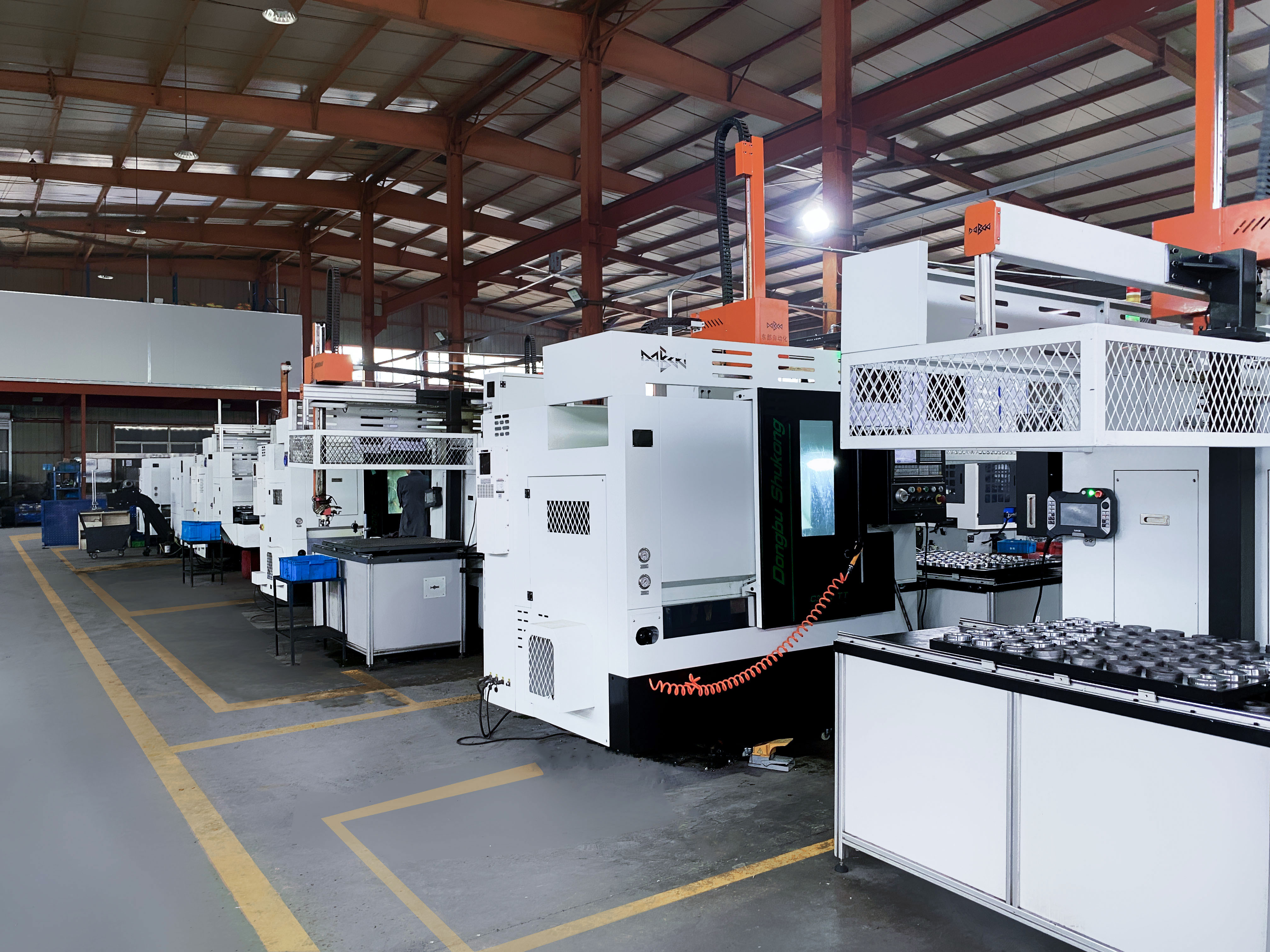
Kapag handa ka nang gawin sa realidad ang iyong aluminum prototype design, ang machining plan ang lugar kung saan nagtatagpo ang mga ideya at katiyakan. Mukhang kumplikado? Isipin mong nagse-set up ka ng cNC MILLING MACHINE —bawat toolpath at pagpili ng cutter ay maaaring magtagumpay o magpabigo sa resulta. Ang tamang estratehiya ay hindi lamang nagpapataas ng kahusayan kundi nagagarantiya rin na ang iyong ginawa sa CNC na Mga Prototype nagkakasya sa masikip na tolerances at mahihigpit na automotive standards.
- Adaptive clearing para sa mabilis na pagtanggal ng materyal—mainam para sa mabilis na pag-ukit o pagbubutas habang minimitahan ang tool wear.
- Climb milling upang mapabuti ang surface integrity at palawigin ang tool life, lalong mahalaga para sa aluminum na madaling kapitan ng built-up edge.
- Mga huling paggiling na may magaan na hakbang sa paglipat sa mga surface ng sealing o mating, upang masiguro ang kailangang-kailangan na kakinisan para sa mga gaskets at O-rings.
- Pumili ng matalas na mga carbide tool na may angkop na mga coating (tulad ng TiAlN o ZrN) upang bawasan ang pagkapit at mapabuti ang pag-alis ng mga chip.
- Panatilihin ang tamang daloy ng coolant at pag-alis ng mga chip upang maiwasan ang muling pagputol sa mga chip, na maaaring makapinsala sa surface at masira ang tool.
- Minimisahin ang paglabas ng tool—mas maikling tool ay nagpapabawas ng ingay at pag-undol, lalo na sa manipis o malalim na bahagi.
Bago ilabas ang anumang programa sa shop floor, simulprehin palagi ang mga toolpath sa iyong CAM software. Nakakatulong ito upang mahuli ang mga posibleng collision, isyu sa abot ng tool, o hindi epektibong paggalaw na maaaring magdagdag ng hindi kinakailangang oras o panganib ng sira.
Fixture para sa Katatagan at Pag-uulit
Nakaranas ka na ba ng problema sa isang bahagi na hindi man lang tumitigil sa lugar? Mahalaga ang epektibong fixturing para sa paggawa ng cnc —ito ang nagpapanatili sa iyong prototype na matatag, tumpak, at maipapaulit sa bawat operasyon. Narito ang ilang paraan para maisakatuparan mo ito nang maayos:
- Paggamit malambot na panga o mga pasadyang fixture para sa kumplikadong mga contorno at delikadong mga tampok.
- Para sa malalaking, patag na plato, isaalang-alang ang mga yugto ng vacuum upang ipamahagi ang pwersa ng pagkakabit nang walang pagbaluktot.
- Magdagdag ng mga tab o mga rib ng suporta para sa manipis o matitigas na bahagi—maaaring alisin ang mga ito sa huli upang mapanatili ang katumpakan ng sukat.
- Pangkatang mga tampok na nagbabahagi ng mga datum sa isang solong setup upang minumahan ang pag-uulit at pag-stack ng mga toleransiya.
- I-document ang lokasyon ng fixture at mga paraan ng pagkakabitan sa iyong mga setup sheet para sa pagkakapare-pareho sa lahat ng pagtakbo.
| Uri ng Feature | Inirerekomendang Workholding | Diskarte sa Toolpath | Paraan ng pagsusuri |
|---|---|---|---|
| Mga Bored Holes | Mga Soft jaws, precision vise | Pagbabarena, pagpapalapad | Sukat ng butas, CMM |
| Mga Manipis na Pader | Pasadyang fixture, plate ng vacuum | Magaan na climb milling, pinakamaliit na step-over | Mikrometro, profilometer |
| Mahabang Mga Puwang | Mga parallel clamp, tab supports | Adaptive clearing, finish pass | Mga divider, CMM |
| O-Ring Grooves | Mga pababag, rotary fixture | Contour toolpath, magaan na finish | Profilometer, visual check |
Target Surface Finish Kung Saan Ito Mahalaga
Hindi lahat ng surface ay nangangailangan ng mirror finish. Ituon ang iyong mga mapagkukunan kung saan ito mahalaga—sa sealing faces, bearing surfaces, at anumang bahagi na kaseguwahan ng ibang parte. Tukuyin ang mga simbolo ng surface finish (tulad ng Ra values) sa iyong mga drawing na eksklusibo para sa mga functional zones na ito. Para sa mga hindi gaanong kritikal na lugar, maaaring iwasan ang masyadong detalyadong milled finish upang makatipid ng oras at gastos. Bago ipadala ang mga bahagi para sa finishing, tukuyin ang inaasahan para sa deburr at break-edge upang maprotektahan ang mga manggagawa sa pag-aassembly at mga seals. Ito ay mahalagang hakbang sa cNC Prototype Machining , dahil ang matatalas na gilid ay maaaring magdulot ng mga panganib sa kaligtasan o pagkabigo sa pag-seal.
Itala ang mga kritikal na inspeksyon—tulad ng flatness, roundness, o surface roughness—malapit sa kanilang mga katangian sa drawing. Ginagawa nitong madali para sa mga quality team na i-verify ang mga kinakailangan at bawasan ang panganib ng hindi napansin na specs.
"Ang isang mabuti nang na-optimize na plano sa pag-machining ay nagbabalance ng bilis, katatagan, at tapos—huwag masyadong i-engineer kung saan hindi kinakailangan, ngunit huwag ring balewalain ang mga kritikal na bahagi."
- I-simulate ang abot ng tool at collision sa CAM bago ilabas ang programa.
- Tiyaking matatag ang fixture para sa bawat operasyon.
- Suriin ang mga kinakailangan sa tapusin ang ibabaw at i-mask lamang ang mga functional na ibabaw kung kinakailangan.
- I-document ang mga pamamaraan ng inspeksyon para sa lahat ng kritikal na bahagi.
Gamit ang isang matibay na plano sa pag-machining at fixturing, handa na ang iyong grupo na makagawa ng mga prototype na bahagi ng mataas na kalidad nang mabilis at maaasahan. Susunod, makikita mo kung paano maplano ang pagtatapos at mga paggamot sa ibabaw upang maprotektahan at mapaganda ang iyong mga custom na aluminum na bahagi ng sasakyan.
Hakbang 6: Magplano ng Pagtatapos at Mga Pagtrato sa Ibabaw para sa Aluminum Prototypes
Pumili ng Mga Tapusin para sa Function at Tibay
Kapag dumating ka sa yugto ng pagtatapos sa mabilis na prototyping para sa custom na aluminum na mga bahagi ng sasakyan, ang iyong mga pipiliin ay magpapasiya hindi lamang kung paano ang itsura ng iyong aluminum prototype mga itsura, kundi pati kung paano ito gumaganap sa tunay na mundo. Nakakatamad isipin? Isipin mo ang isang bahay-baterya o isang bracket na nalantad sa asin sa kalsada, init, at pag-ugoy—ang paggamot sa ibabaw ay maaaring mag-iba sa pagitan ng isang bahagi na pumasa sa pagpapatunay at isa na nabigo sa field.
Hatiin natin ang pinakakaraniwang mga opsyon sa pagtatapos, upang pumili ka ng pinakamahusay na tugma para sa iyong bahagi:
| Finish Type | Paggana | Mga Tipikal na Aplikasyon | Mga Isinasaalang-alang sa Dimensyon | Kakayahang magkasya ng Alloy |
|---|---|---|---|---|
| Anodizing (Pandekorasyon/Hardcoat) | Tumutulong sa korosyon at pagsusuot, mga opsyon sa kulay | Mga panlabas na trim, mga bahay, mga bracket | Nagtatayo ng layer (~0.002"), maaapektuhan ang pagkakasya | Pinakamahusay na kasama ang 6061, 5052, ilan sa serye ng 7000 |
| Chromate Conversion (Chem Film/Alodine) | Pagkapit ng pintura, pagkakasunod ng kuryente, resistensya sa mababang korosyon | Mga punto ng pagbaba, paghahanda bago magpinta | Pinakamaliit na pagbabago ng kapal | Saklaw ang karamihan sa mga haluang metal ng aluminum |
| Bead blasting | Unipormeng matte/satin na tapusin, nag-aalis ng mga marka ng tool | Mga nakikitang ibabaw, paghahanda bago mag-anodize | Walang makabuluhang pag-akyat; maaaring bahagyang mag-etch | Lahat ng karaniwang haluang metal |
| Pulbos na Patong/Pintura | Proteksyon mula sa UV/korosyon, kulay at tekstura | Mga panel, takip, at mga bahagi para sa disenyo | Nagbubuo ng kapal, maaaring punan ang maliit na mga detalye | Lahat ng karaniwang haluang metal |
Mapapansin mo na anodized ang mga tapusin ay ang pinakamainam para sa paglaban sa pagsusuot at korosyon, lalo na para sa mga bahagi na nakakalantad sa matitinding kondisyon o nangangailangan ng pagkakaiba-iba ng kulay. Para sa tuloy-tuloy na kuryente o kapag nag-aayos para sa pagpipinta, ang chromate conversion (chem film o Alodine) ay angkop dahil ito ay nagpapanatili ng conductivity at nagdaragdag ng kaunting proteksyon laban sa korosyon. Kung gusto mo ng isang maayos at pare-parehong itsura o kailangan mong tanggalin ang mga bakas mula sa pagmamanupaktura, ang bead blasting gamit ang bead blaster ay nagbibigay ng isang pantay na dulap na tapusin nang hindi nagbabago nang malaki sa sukat.
Isaalang-alang ang Pagbabago ng Sukat at Masking
Naranasan mo na bang dumating ang isang bahagi mula sa pagtatapos at biglang hindi na umaayon? Ito ay karaniwang dulot ng pagbubuo ng kapal mula sa mga patong tulad ng powder o anodizing. Magplano nang maaga sa pamamagitan ng:
- Pagtukoy sa mga kritikal na sukat at pagtala kung aling mga ibabaw ang dapat takpan upang maprotektahan ang mga pagkakatugma o punto ng koneksyon sa kuryente.
- Pagdokumento ng mga lugar na dapat takpan nang direkta sa iyong mga drawing—isipin ang mga butas, thread, o ground stud.
- Iayon ang iyong sequence ng pagtatapos sa inspeksyon: gawin ang CMM checks bago tapusin, pagkatapos ay spot-check ang masked at natapos na mga lugar pagkatapos.
- Nagtatakda ng proteksyon sa touchpoint para sa sealing faces, upang maayos na umupo ang gaskets at O-rings.
Ang pagmamaskara ay lalong mahalaga para sa aluminum prototype mga bahagi na may siksik na pagkakatugma o kung saan kinakailangan ang conductivity. Halimbawa, dapat iwanang nakalantad ang chromate conversion sa ground points, habang ang anodizing o powder coat ay maaaring tumakip sa cosmetic surfaces.
Maghanda ng Ibabaw para sa Paint at Assembly
Bago ipadala ang iyong parte para sa pagpinta o perpera, tiyaking malinis ang surface at natutugunan ang anumang kinakailangan sa rugosidad para sa adhesive bonding o gasket sealing. Narito ang isang praktikal na tseklis:
- Tukuyin ang kulay at ningning lamang kung saan ito mahalaga—ang sobrang pagtukoy ay maaaring magdagdag ng hindi kinakailangang gastos at kumplikado.
- Tukuyin ang cleanliness at roughness ng ibabaw sa mga adhesive o sealing zone.
- Isama ang mga coating ng fastener kasama ang iyong napiling finish upang maiwasan ang galvanic corrosion—huwag kailanman pagsamahin ang magkakaibang metal nang walang insulation.
- Tiyaking ang mga vendor ng tapos ay mayroong mga parehong drawing at tawag tulad ng mga machinist sa pamamagitan ng paglalagay ng isang routing note sa iyong traveler.
Isipin mong ikaw ay nagpe-prep ng isang bracket para sa powder coating: nais mong i-blast muna ito ng bead upang matiyak ang pagkakadikit ng pintura, pagkatapos ay takpan ang lahat ng threaded hole at sealing face. Kung ang iyong assembly ay umaasa sa electrical grounding, tiyaking ang mga bahaging iyon ay pinabayaang walang tapis o tinapal na chromate conversion imbes na pintura o anodize.
"Ang isang mabuting plano ng pagtatapos ay nagpoprotekta sa iyong bahagi, pinapabilis ang assembly, at nagpapatunay na ang iyong prototype ay natutugunan ang parehong cosmetic at functional na layunin."
Gamit ang mga pinakamahusay na kasanayan sa pagtatapos, ang iyong proseso ng mabilis na prototyping ay hindi lamang maganda ang hitsura aluminum prototype kundi pati na rin ang isang bahagi na handa na para sa tunay na automotive na tungkulin. Susunod, tataya ang gastos, lead time, at ilalagay ang mga buffer ng kontingensiya upang mapanatili ang iyong programa sa tamang landas.
Hakbang 7 Planuhin ang Gastos, Lead Time, at Mga Kontingensiya para sa Aluminum Prototypes
Tayahin ang Time-to-First-Part Sa Lahat ng Paraan
Kapag ikaw ay nagmamadali sa isang deadline sa paglulunsad, paano mo mahuhulaan kung aling proseso ng prototyping ang magbibigay sayo ng bahagi nang mas mabilis? Isipin mong kailangan mo ng isang bracket para sa pilot build o isang housing para sa functional testing. Bawat pamamaraan - CNC machining, sheet metal, metal 3D printing, casting na may prototype tooling, o extrusion kasama ang CNC - ay may sariling bilis at kumplikasyon. Narito ang isang paghahambing ng bawat isa:
| Paraan ng Prototyping | Relatibong Bilis | Kumplikasyon ng Order | Pangunahing Mga Dahilan ng Gastos | Mga Salik/Paraan |
|---|---|---|---|---|
| CNC gawa sa Plate | Mabilis na umpisa (ilang araw hanggang 1 linggo) | Mababa para sa isang beses lang, katamtaman para sa kumplikadong mga bahagi | Mga Setup, siksik na toleransiya, espesyal na cutter | Stock ng materyales, programming ng toolpath, inspeksyon |
| Pagbuo ng sheet metal | Mabilis kung standard ang tooling; mas mabagal kung may pasadyang pag-bend/hem | Simple para sa mga bracket, mas kumplikado para sa mga enclosure | Setup ng tooling, kumplikado ng pag-bend, pagtatapos | Mabilis na sheet metal, access sa standard die, queue para sa pagtatapos |
| Pagprint sa 3D gamit Metal | Mabilis na simula (1-2 araw), mas matagal na post-processing | Pinakamahusay para sa mga kumplikadong panloob, lattice | Oras ng pagpi-print, pagtanggal ng support, post-machining | Kakayahang ma-access ang makina, oryentasyon ng parte, pagtatapos |
| Casting kasama ang Prototype Tooling | Mas mabagal na simula (tooling lead time), mainam para sa masa | Katamtaman hanggang mataas; nakadepende sa geometry | Prototype tooling, mold setup, secondary ops | Rapid prototype tooling, material pour, finishing |
| Ekstrusyon + CNC | Profile lead time (weeks), mabilis na machining pagkatapos ng extrusion | Simple para sa mahabang, uniform na profile | Paglikha ng die, extrusion run, CNC finishing | Die queue, laki ng batch, secondary ops |
Mapapansin mo na mabilis na cnc madalas na ang machining ang pinakamabilis na paraan para sa isa-lamang o maikling produksyon ng mga bahagi, lalo na kung simple ang geometry. Hindi matatalo ang sheet metal para sa mga bracket at enclosures kung maaari mong gamitin ang umiiral na dies. Sumisigla ang metal 3D printing kapag kailangan mo ng mga kumplikadong panloob na tampok, ngunit maghanda para sa karagdagang post-processing. Mas matagal ang simula ng prototype at maikling serbisyo ng casting at extrusion ngunit mabisa kapag kailangan mo ng higit sa ilang piraso lamang ng mga bahagi.
Matukoy ang Pangunahing Mga Salik sa Gastos nang Maaga
Ano ang nagpapakaiba sa gastos ng isang prototype na $200 at isa pang $2,000? Ang sagot ay nasa pag-unawa sa pangunahing mga salik sa gastos para sa bawat proseso. Narito ang dapat mong bantayan:
- Mga Setup at Mahigpit na Tolerance: Mas maraming setup at mas mahigpit na espesipikasyon ay nangangahulugan ng higit na oras at mas mataas na gastos sa inspeksyon.
- Mga Espesyal na Cutter o Fixture: Nagdaragdag ng oras at gastos ang custom na kagamitan, lalo na para sa mga kumplikadong bahagi o mabilis na pagtrato sa sheet metal.
- Kakailanganin sa Materyales: Maaaring mapabagal ng rare alloys o makakapal na stock ang proseso kahit sa pinakamahusay na mabilis na Serbisyo sa Prototyping .
- Oras sa Pagtatapos: Maaaring magdagdag ng ilang araw ang mga pagtrato sa ibabaw tulad ng anodizing o powder coat kung mahaba ang pila ng supplier.
- Kumplikadong inspeksyon: Ang mga bahagi na may maraming kritikal na sukat o pangangailangan sa ibabaw ay nangangailangan ng higit na oras sa CMM o manwal na mga sukatan.
Para sa cnc mabilis na prototyping , isaalang-alang ang pagpapasimple ng iyong disenyo upang mabawasan ang mga setup, paluwagin ang mga toleransiya kung maaari, at i-grupo ang mga bahagi upang magbahagi ng mga fixture. Para sa paghuhulma o pagpilit, ang gastos ng prototype na kagamitan ay isang malaking paunang driver—kaya lamang pumunta sa ganitong paraan kung malamang na ulitin mo ang disenyo o kailangan mong masuri ang masa ng mga katangian.
Gumawa ng Iskedyul na May Buffer para sa Panganib
Paano mo mapapanatili ang iyong iskedyul na nasa tamang landas habang bawat yugto ay may sariling sorpresa? Ang sagot: magplano para sa hindi kilalang sa pamamagitan ng pagbuo ng mga buffer at malinaw na komunikasyon. Narito ang mga praktikal na paraan upang mapabilis ang lead time at mabawasan ang panganib:
- Paluwagin ang mga hindi kritikal na toleransiya—tanungin kung sapat na ba ang ±0.1 mm sa halip na ±0.01 mm para sa mga estetiko.
- Ipagkaisa ang mga setup at i-bundle ang mga bahagi sa iisang fixture kung maaari.
- Unang aprubahan ang mga tapusin at iwasan ang mga pagbabago sa huling minuto na maaaring magka-delay sa paghahatid.
- Magbigay ng malinis, kumpletong naka-dimensyon na STEP files at PDF drawings sa bawat supplier—ito ay mahalaga para sa mabilis na prototyping manufacturing.
- Magdagdag ng puwang para sa posibleng pagbabago sa pagtatapos at pag-adjust ng dimensyon sa pagitan ng mga yugto.
I-quote nang tama sa pamamagitan ng pagpadala ng parehong malinis na STEP, kumpletong naka-dimensyon na PDF, at mga tala sa pagtatapos sa lahat ng supplier.
I-document ang cycle-time insights pagkatapos ng bawat yugto—mayroon bang proseso na tumakbo nang mas mabilis kaysa inaasahan, o nagdagdag ba ng pagka-antala ang isang partikular na pagtatapos? Ang mga natutunan ay makatutulong upang mapaganda ang iyong pamamaraan para sa hinaharap na prototype at maikling produksyon o kapag tataas ang dami ng produksyon.
Sa pamamagitan ng paghahanda para sa mga hindi inaasahang pangyayari at pag-unawa sa mga pangunahing driver ng gastos, maitatakda mo ang realistiko na mga inaasahan at maiiwasan ang mga mahalagang sorpresa. Susunod, makikita mo kung paano i-validate ang kalidad at pagganap ng iyong prototype—tinitiyak na bawat puhunan at araw ay magbabayad sa huling produkto.

Hakbang 8 Suriin, Subukan, at I-record ang mga Natutunan para sa Aluminum Prototypes
Tukuyin ang Pagsusuri para sa Mahahalagang Feature
Kapag sa wakas ay nasa iyong kamay na ang prototype, paano mo malalaman na talagang handa na ito para sa anumang gawain sa industriya ng automotive? Isipin ang paglalagay ng mga linggo ng pagsisikap sa mataas na tumpak na prototyping , lamang upang malaman na may malubhang isyu sa pagkakatugma habang isinasama ang mga bahagi. Iyan ang dahilan kung bakit mahalaga ang isang nakaplanong inspeksyon para sa mga pasadyong bahagi ng sasakyan na gawa sa aluminum. Parang marami? Baliktarin natin ito sa mga praktikal na hakbang na magagarantiya na ang iyong bahagi ay makakatugon sa bawat kinakailangan—bago pa man ito makarating sa kalsada.
- Plano sa Pagmemeasurement: Isabay ang iyong paraan ng inspeksyon sa paraan ng pagkaka-fixtured ng bahagi. Gamitin ang CMM (Coordinate Measuring Machine) para sa posisyon ng mga feature, gauge para sa mga thread at bore, at surface roughness tester para sa sealing faces. Halimbawa, kung ang mounting holes ng iyong bracket ay kritikal, suriin ang kanilang eksaktong posisyon at lapad gamit ang CMM at plug gauge.
- Pagsusuri sa Tugma sa Assembly: Subukan ang prototype kasama ang aktwal na mating hardware. Itala ang mga torque values para sa fasteners, talaan ang anumang interference, at i-dokumento ang assembly sequence. Ang mga fit notes na ito ay mahalaga para paunlarin ang iyong precision prototype para sa susunod na iteration.
- Pagsusuri ng Kagamitan: Patunayan ang iyong parte sa ilalim ng tunay na kondisyon sa automotiko—isipin ang vibration, thermal cycling, o pagkalantad sa mga likido. Sa halip na hula-hulaan, tingnan ang mga itinatag na pamantayan tulad ng ASTM para sa waterproofing o ISO para sa vibration. Kung ang iyong housing ay dapat manatiling walang leakage, gawin ang seal tests sa tinukoy na presyon at tagal.
- Pagsusuri sa Tapos na Bahagi: Suriin ang lahat ng coated o treated surfaces para sa adhesion, kapal, at kalidad ng itsura. Bigyan ng espesyal na atensyon ang mga masked zones—ang mga threads, bores, o ground points ba ay angkop na napoprotektahan? Ang visual at tactile inspection, kasama ang thickness gauges, ay tumutulong upang kumpirmahin ang kalidad ng tapos na bahagi.
- I-update ang Dokumentasyon: Ang anumang isyu o tagumpay ay dapat maituturing sa iyong CAD models at drawing. Kung ang isang tolerance ay sobrang sikip o isang feature ay hindi kinakailangan, mangyaring baguhin ang dokumentasyon bago ang susunod na pagbuo.
| Uri ng Feature | Paraan ng pagsukat | Dokumentasyon ng Pagtanggap |
|---|---|---|
| Mounting holes | CMM, Plug Gage | Ballooned Drawing, Ulat sa Pagsusuri |
| Mukha ng Pag-seal | Pamantayan ng Katigasan ng Sufis | Tumutukoy sa Kahit anumang Kahon sa Ibabaw, Biswal/Haplos na Pagsusuri |
| Mga Thread at Mga Butas | Thread Gage, Bore Gage | Log ng Pagsusuri, Pagbabago sa Drawing |
| Mga Patong/Huling Ayos | Sukat ng Kapal, Biswal na Pagsusuri | Sertipiko ng Tapusin, Tseklis ng Pagmamaskara |
| Kabuuan ng Materiales | Pagsusuri ng Kemikal, Sertipiko ng Materyales | Punong Pakete ng Sertipiko ng Materyales |
I-verify ang Pagganap Sa Iba't Ibang Tunay na Kondisyon
Ang pagsubok ay hindi lamang tungkol sa pagtsek ng mga kahon—ito ay tungkol sa pagtitiyak na ang iyong bahagi ay gumaganap sa larangan. Isipin ang isang kahon ng baterya na dapat umaguant sa init at pag-vibrate sa ilalim ng hood. Sa pamamagitan ng paggaya sa mga tunay na kondisyong ito, makakatuklas ka ng mga kahinaan bago pa ito maging mabigat na pagkabigo. Gamitin ang kompletong serbisyo ng prototype upang patakbuhin ang thermal cycling, vibration, at corrosion tests na kopya ng tunay na kapaligiran sa kotse. Lagi nating iugnay ang bawat pagsubok sa isang tiyak na kinakailangan mula sa dokumentasyon ng iyong disenyo, at huwag mag-atubiling ihiwalay ang mga pagsubok—suriin nang hiwalay ang pagganap ng sealing mula sa impact resistance, halimbawa. Ang ganitong target na paraan ay isang katangian ng epektibong precision prototyping at pagmamanufaktura .
- Mga pagsubok sa thermal cycling para sa mga bahagi na nalantad sa init ng engine o baterya
- Pagsusuri sa pagyanig at pagbugso para sa mga bracket at mounts
- Mga pagsusuring katugma sa likido para sa mga housing o takip
- Mga pagsusuri sa pagkapit at pagkalat ng kahoy sa mga natapos na surface
Itala ang lahat ng resulta, kabilang ang mga kinalabasan na pumasa/hindi pumasa at anumang paglihis sa inaasahang pagganap. Kung ang isang bahagi ay hindi nagtagumpay, suriin ang pinagmulan—ito ba ay isang isyu sa materyales, isang depekto sa disenyo, o isang pagbabago sa proseso? Ang feedback loop na ito ang siyang nagpapalit ng isang prototype sa isang solusyon na handa na sa produksyon.
Ilagay ang Mga Resulta para sa Susunod na Iterasyon
Tila maraming dokumentasyon? Isipin ang oras na makokonserba kapag maibibigay mo sa iyong supplier ang isang kumpletong package ng traceability. Pagnilayan ang mga sertipiko ng materyales, sertipiko ng tapusin, at mga process traveler sa isang solong file. Gamitin ang isang log ng paglihis upang subaybayan ang mga isyu at pagkilos na paliwanag, upang mapadali ang komunikasyon kasama ang iyong grupo at mga nagbibili para sa susunod na pagkakataon.
Narito ang isang praktikal na checklist para sa dokumentasyon:
- Mga drawing na may bilog na numero na konektado sa mga ulat ng inspeksyon
- Mga sertipiko ng materyales at tapusin
- Mga tala sa pagkakasunod ng pagtitipon at mga tala ng torque
- Mga resulta ng functional test at mga analisis ng pinagmulan ng problema
- Na-update na CAD/mga drawing file na nagpapakita ng lahat ng pagbabago
I-validate ang function, pagkatapos ay i-lock ang mga tolerance na talagang nagdudrive ng performance.
Sa pamamagitan ng pagkuha ng mga natutunan, hindi ka lang nagtatapos ng loop—kundi nagtatayo ka ng isang knowledge base na magpapabilis sa hinaharap metal prototyping at produksyon. Ang diskarteng ito ay sentro sa precision prototyping at pagmamanufaktura , na nagpapakita na ang bawat prototype ay nagdadala sa iyo nang mas malapit sa isang matibay at mura ang gastos na automotive component. Handa ka na bang gumawa ng susunod na hakbang? Ang huling yugto ay sumasaklaw kung paano i-package ang iyong mga natuklasan para sa mga supplier RFQ at pumili ng perpektong kasosyo para sa iyong susunod na build.
Hakbang 9 Ipadala ang RFQs at Pumili ng Tamang Partner para sa Iyong Aluminum Prototypes
Gumawa ng isang Kompletong RFQ Package
Kapag handa ka nang lumipat mula sa disenyo patungo sa pagmamanupaktura, ang iyong Request for Quotation (RFQ) package ay iyong gabay para sa tagumpay. Nakakatakot ba? Isipin ang pagpapadala ng hindi kumpletong mga file at makakatanggap ng isang dosenang hindi tugmang mga quote—nakakabigo at nakakapagod. Sa halip, ang mabuti at maayos na RFQ ay nagpapabilis sa proseso at tumutulong sa mga kumpanya ng prototype na lubos na maintindihan ang iyong mga pangangailangan.
- Idagdag ang mga digital design file: Isama ang malinis na STEP o Parasolid model at isang kumpletong ballooned PDF drawing upang linawin ang bawat kritikal na bahagi.
- Tukuyin ang materyales at temper: Maliwanag na sabihin ang aluminum alloy at temper upang maiwasan ang pagkalito o mga kapalit.
- Ilista ang mga kinakailangan sa pagtatapos (finish): Tukuyin ang mga surface treatment, masking zones, at kulay o antas ng kinaragatan kung kinakailangan.
- Tukuyin ang mga dami at target na paghahatid: Nag-uutos ka ba ng isang prototype, isang pilot batch, o isang maikling produksyon?
- I-highlight ang mga kritikal na sukat at paraan ng inspeksyon: Ipakita kung aling mga tampok ang nangangailangan ng CMM, plug gages, o espesyal na pagsusuri.
- Mga detalye ng fixturing o masking na kailangan: Kung kailangan ng espesyal na fixtures o masking, i-dokumento ito nang maaga.
- Isama ang alternatibo: Imungkahi ng backup alloys o proseso kung may alalahanin sa supply o lead time.
- Magdagdag ng mga larawan o cross-sectional view: Para sa mga mahirap na tampok, ang visual reference ay maaaring maiwasan ang pagkakamali.
- Tukuyin ang patakaran sa pagpapalit: Gawing malinaw kung ang ilang mga pagbabago ay nangangailangan ng iyong pahintulot.
Sa pamamagbigay ng ganitong antas ng detalye, tinutulungan mo ang mga kumpanya na gumawa ng prototype na magbigay ng tumpak na quote at maiwasan ang mahal na mga sorpresa sa hinaharap.
Maikling Listahan ng mga Supplier na Naayon sa Iyong Proseso
Ang pagpili ng tamang kasosyo ay hindi lamang tungkol sa presyo—it ay tungkol sa paghahanap ng mga kompanya ng prototype na naaayon sa iyong mga pangangailangan para sa kalidad, bilis, at suporta sa engineering. Isipin mong ipadala ang iyong RFQ sa isang dosenang mga vendor at makatanggap ng mga quote na nag-iiba-iba ng ilang linggo sa lead time at libu-libo sa gastos. Paano mo ihahambing ang mansanas sa mansanas?
| Nagbibigay | Pangunahing Kakayahan | Oras ng Paggugol | MGA SERTIPIKASYON | Suporta sa Engineering | Mga pagpipilian sa palitan ng ibabaw | Karanasan sa Automotive |
|---|---|---|---|---|---|---|
| Shaoyi Metal Parts Supplier | In-house extrusion, CNC, surface treatments, DFM, rapid prototyping service | 24-oras na quote, mabilis na paggawa ng prototype | IATF 16949, ISO 9001 | Dedikadong automotive engineering team, DFM analysis | Anodize, nickel, paint, custom masking | 80%+ automotive, naipakita na kasama ang mga global na OEM |
| Rehiyonal na CNC Job Shop | CNC machining, basic finishing | 3-10 araw na karaniwan | ISO 9001 (nag-iiba) | Limitado, karaniwang ayon sa trabaho | Basic anodize/powder coat | Pangkalahatang industriyal, limitadong auto focus |
| Metal AM Bureau | Metal 3D printing, post-machining | 5-15 araw | ISO 9001 (nag-iiba) | Design for AM, some DFM | Bead blast, kaunting masking | Medyo may automotive |
| Prototype Foundry | Aluminum casting, secondary CNC | 2-4 na linggo | ISO 9001 (nag-iiba) | Payo na partikular sa proseso | Pinta, chromate, basic anodize | Konting automotive, karamihan ay industrial |
Pansinin kung paano Shaoyi Metal Parts Supplier nagmumukha, lalo na para sa mga serbisyo ng pag-unlad ng prototype ng aluminum na may maraming proseso o nakabatay sa ekstrusyon. Ang kanilang pinagsamang paraan, mabilis na pagkuwota, at pokus sa automotive ay nagpapahusay sa kanila para sa mga pangangailangan sa mabilis na pagpoprototype, lalo na kapag kailangan mo ng parehong bilis at kalidad. Para sa mas partikular na mga pangangailangan, ang mga lokal na shop para sa CNC o mga metal AM bureau ay maaaring maging mahalagang kasosyo, ngunit maaaring kulang sa kalaliman ng pagtatapos o suporta sa DFM na makikita sa mga dedikadong kumpanya ng prototype manufacturing.
Gumawa ng Mapanatag na Desisyon
Paano nga ba pipiliin ang mga kumpanyang gagawa ng prototype para sa iyong proyekto? Higit pa sa presyo, isaalang-alang ang mga sumusunod na kriteria:
- Pagiging tumutugon: Nakakasagot ba sila nang mabilis at malinaw?
- Suporta ng DFM: Nakikinita ba nila ang pagmungkahi ng mga pagbabago sa disenyo para sa pagmamanupaktura?
- Pagtatapos ng integrasyon: Kayang ba nilang gawin ang lahat ng pagtatapos nang internal o maayos na ikoordinado?
- Dokumentasyon ng kalidad: Ibibigay ba nila ang mga ulat sa inspeksyon, mga sertipiko ng materyales, at pagsubaybay?
- Karanasan sa Automotive: Nauunawaan ba nila ang mga kinakailangan sa regulasyon at pagganap na natatangi sa mga bahagi ng kotse?
- Kapasidad at kakayahang umangkop: Kayang ba nilang lumipat nang madali sa pagitan ng prototype at maliit na produksyon habang umuunlad ang iyong mga pangangailangan?
Isipin mong nagba-bulk up ka mula sa isang prototype papunta sa maikling produksyon para sa field testing. Ang perpektong kasosyo ay isang kumpaniya ng mabilis na prototyping na lumalago kasama mo—nag-aalok ng engineering input at matibay na quality control sa bawat yugto.
Pumili ng mga kasosyo na mapapahusay ang iyong disenyo, hindi lang babasahin ito.
Sa pamamagitan ng pagbuo ng isang kumpletong RFQ, paghahambing ng mga kakayahan, at pagtimbang sa mga kriterya sa pagpili, makakahanap ka ng mga kumpaniya ng prototype na gumagawa ng higit sa paghahatid ng mga parte—naging mga kasama sila sa tagumpay ng iyong produkto. Handa ka nang magpatuloy? Kasama ang tamang supplier, naka-ayos na ang iyong custom na aluminum automotive components para sa mas maayos at mabilis na transisyon mula sa konsepto hanggang sa kung saan naabot ng realidad.
Mga madalas itanong
1. Ano ang pinakamahusay na aluminum alloy para sa mabilis na prototyping ng custom na automotive components?
Ang pinakamahusay na kakaunting haluang metal ay depende sa tungkulin ng iyong bahagi. Ang 6061 ay mataas na mapapakinabangan at angkop para sa mga istrukturang bracket, samantalang ang 5052 ay mahusay sa paghubog ng sheet metal dahil sa kanyang superior na kakayahang umusbong. Para sa mga pangangailangan ng mataas na lakas, maaaring piliin ang 7075, ngunit ito ay mas mahirap i-weld at mahirap hubugin. Palaging isaalang-alang ang kagamitan sa imbentaryo, mga paraan ng pagdok, at kailangang mga tapusin upang makagawa ng pinakamahusay na pagpili.
2. Paano nakikinabang ang mga pasadyang automotive project sa mabilis na prototyping?
Ang mabilis na prototyping ay nagpapabilis sa pagpapatunay ng disenyo, binabawasan ang oras bago ilunsad sa merkado, at nagbibigay ng mabilis na pagpapabuti batay sa tunay na pagsubok. Ang mga serbisyo tulad ng Shaoyi Metal Parts Supplier ay nag-aalok ng pinagsamang pagsusuri ng disenyo, mabilis na pagkalkula ng presyo, at nakatuon sa linya ng prototyping, na nagsisiguro na ang mga bahagi ay nakakatugon sa kalidad at pamantayan ng pagganap ng automotive mula pa sa unang sample.
3. Ano ang pangunahing mga hakbang sa proseso ng mabilis na prototyping para sa mga bahagi ng sasakyan na gawa sa aluminum?
Kabilang sa mga mahahalagang hakbang ang pagtukoy sa function at mga kriterya ng tagumpay, pagpili ng angkop na aluminum alloy at temper, pagpili ng pinakamahusay na paraan ng prototyping, paglalapat ng mga prinsipyo ng design-for-manufacture, pagplano ng machining at finishing, pagtataya ng gastos at lead time, pagpapatunay ng kalidad, at pagpili ng tamang supplier para sa produksyon.
4. Paano ko matitiyak ang kalidad at katiyakan sa mga bahagi ng prototype ng aluminum?
Napapanatili ang kalidad sa pamamagitan ng isang nakabalangkas na plano ng inspeksyon: gamitin ang CMM para sa mga kritikal na tampok, subukan ang pagkakatugma sa assembly, isagawa ang functional at finish checks, at i-dokumento ang lahat ng resulta. Ang mga supplier tulad ng Shaoyi ay nag-aalok ng IATF 16949 na sertipikadong proseso, materyales at finish na may dokumentasyon, at DFM suporta sa loob ng bahay upang matiyak ang mataas na katiyakan mula sa prototype hanggang sa produksyon.
5. Bakit pipiliin si Shaoyi para sa automotive aluminum prototyping?
Nagbibigay si Shaoyi ng one-stop solution na may in-house na extrusion, machining, at finishing, rapid prototyping services, at IATF 16949 sertipikadong kalidad. Ang kanilang espesyalisasyon sa automotive, mabilis na quote turnaround, at malalim na engineering expertise ay tumutulong sa mga kliyente na bawasan ang panganib, mapabilis ang supply chain, at makamit agad ang matibay at mataas na kalidad na mga bahagi.