 Maliit na mga batch, mataas na pamantayan. Ang serbisyo sa paggawa ng mabilis na prototyping namin ay gumagawa ng mas mabilis at mas madali ang pagpapatunay —

Panghihigpit ng Precision Sheet Metal: Pagpapakatatag ng Springback, Tooling, at Toleransya
Pag-unawa sa Presisyong Pagkukurba ng Sheet Metal at Bakit Mahalaga ang mga Pasanay
Kapag nagtatrabaho ka sa pagkukurba ng sheet metal, maaaring magtanong ka: ano ba talaga ang naghihiwalay sa isang "sapat na" kurba mula sa isang tunay na presisyong kurba? Ang sagot ay nasa isang mahalagang kadahilanan—ang mga pasanay. Kung ikaw man ay nagpapagawa ng mga bahagi para sa mga automotive assembly o medikal na device, ang pagkukurba ng sheet metal sa antas ng presisyon ay nangangailangan ng higit pa sa kayang ibigay ng karaniwang operasyon sa pagbuo.
Ang presisyong pagkukurba ng sheet metal ay isang paggawa na may antas ng inhinyero na nakakamit ng mga pasanay sa anggulo na ±0.5° o mas mahigpit pa at mga pasanay sa linear na ±0.2 mm o mas mahusay pa, gamit ang advanced na CNC equipment, espesyalisadong kagamitan, at mahigpit na mga sistema ng quality control.
Ang kahulugan na ito ay hindi arbitraryo. Ito ay sumasalamin sa nakukukuhang pagkakaiba sa pagitan ng pangkalahatang gawaing paggawa at ng mahigpit na pamantayan na kinakailangan kapag ang pagkakasya at pagganap ng mga bahagi ay walang espasyo para sa kamalian.
Ano ang Nagpapagawa ng Pagkukurba na Tunay na Tumpak
Isipin ang pag-aassemble ng isang bahagi ng chasis kung saan ang bawat kurba ng flange ay kailangang mag-align nang perpekto sa mga kasalungat na bahagi. Ang karaniwang toleransya sa paggawa—na karaniwang nasa saklaw na ±1/16" hanggang ±1/8" (±1.6mm hanggang ±3.2mm) —ay hindi sapat. Sa kabilang banda, ang tumpak na pagkukurba ay konsehente na pinapanatili ang toleransya sa pagitan ng ±0.005" at ±0.010" (±0.13 mm hanggang ±0.25 mm) sa mga kumplikadong heometriya.
Ang nagpapabukod ng gawaing tumpak ay hindi lamang ang mas maliit na numero sa isang technical specification sheet. Ito ay isang lubos na iba’t ibang paraan na kasama ang:
- Mga CNC press brake na may real-time na pagsukat ng anggulo at awtomatikong koreksyon
- Mga tool na idinisenyo partikular para sa aplikasyon upang matiyak ang paulit-ulit na katiyakan
- Malalim na pag-unawa sa ugali ng materyales, mga kalkulasyon sa springback, at direksyon ng butil (grain direction)
- Statistical process control at komprehensibong dokumentasyon ng kalidad
Ang bawat desisyon sa eksaktong pagkukurba—mula sa pagpili ng materyales hanggang sa pagpili ng mga kagamitan—ay dumadaan sa isang pananaw lamang: kaya ba nating maabot at panatilihin ang aming target na toleransya?
Ang Mga Pamantayan sa Toleransya na Nagtatakda ng Kalidad
Ang mga espesipikasyon sa toleransya sa mga operasyon ng eksaktong pagkukurba ng sheet metal ay nahahati sa dalawang pangunahing kategorya: angular at dimensional. Ang mga modernong CNC press brake ay karaniwang nakakakamit ng ±0.5° na angular tolerance at ±0.2 mm na linear tolerance para sa karamihan ng mga aplikasyon. Kapag kailangan ng mas mahigpit na kontrol, ang mga operasyon ng coining ay maaaring itaas ang angular accuracy hanggang sa ±0.1° kasama ang linear precision na ±0.1 mm.
Bakit kaya napakahalaga ng mga numerong ito? Sa mga industriya tulad ng automotive, paggawa ng medical device, at telecommunications, ang maliit na pagkakaiba man ay maaaring magdulot ng kabiguan sa assembly o mabawasan ang pagganap ng produkto. Ang isang pagkakaiba na 0.020" na lubos na tinatanggap sa mga aplikasyon sa konstruksyon ay maaaring gawing ganap na hindi magamit ang isang komponente para sa aerospace.
Sa buong artikulong ito, matutuklasan mo kung paano ang bawat aspeto ng eksaktong pagkukurba—mula sa kompensasyon sa springback hanggang sa pagpili ng mga kagamitan—ay direktang nauugnay sa pagkamit ng mga mahigpit na espesipikasyon ng toleransya. Isipin ang mga toleransya hindi bilang mga panghihigpit, kundi bilang pamantayan ng kalidad na nagbibigay-daan sa bawat desisyon sa paggawa na gagawin mo.
Paghahambing sa Air Bending at Bottom Bending at Coining Methods
Ngayon na alam mo na kung paano ang hitsura ng mga eksaktong toleransya, ang susunod na tanong ay: paano nga ba talaga sila makakamit? Ang sagot ay lubhang nakasalalay sa paraan ng pagkukurba na pipiliin mo. Ang mga operasyon sa pagkukurba ng metal ay nahahati sa tatlong pangunahing kategorya—ang air bending, bottom bending, at coining—bawat isa ay may natatanging kakayahan sa eksaktong paggawa . Ang pag-unawa sa mga pagkakaiba ng mga ito ay mahalaga kapag pinipili ang kagamitan sa pagkukurba ng sheet metal para sa iyong aplikasyon.
Air Bending para sa Flexible na Kontrol sa Toleransya
Ang air bending ay ang pinakakaraniwang ginagamit na paraan sa modernong paggawa, at may magandang dahilan para dito. Kapag natututo ka kung paano gamitin ang sheet metal brake, malamang na dito ka magsisimula. Sa prosesong ito, ang punch ay pinipindot ang workpiece nang bahagya papasok sa V-die nang hindi pilitin ang materyal na makipag-ugnayan sa ilalim ng die. Ang anggulo ng pagkukurba ay nakasalalay sa lalim ng pagbaba ng punch—hindi sa hugis ng die mismo.
Ano ang nagpapaganda ng air bending para sa mga aplikasyong nangangailangan ng kahusayan?
- Versatilidad: Maaaring mag-produce ng maraming anggulo ng pagkukurba ang isang solong set ng punch at die, kaya nababawasan ang gastos sa tooling
- Mas mababang kinakailangang tonelada: Kadalasan ay nangangailangan lamang ng 25–50% ng puwersa na kailangan para sa iba pang mga paraan
- Bawasan ang pagkasira ng tooling: Ang mas mababang presyon ng kontak ay nagpapahaba nang malaki ng buhay ng die
- Kahusayan ng Enerhiya: Ang mas mababang kinakailangang puwersa ay nagreresulta sa mas mababang gastos sa operasyon
Gayunman, may malaking hamon ang air bending: ang springback. Dahil ang materyal ay hindi kailanman ganap na sumasalim sa die, mas malinaw ang elastic recovery. Ang pagkamit ng mahigpit na toleransya ay nangangailangan ng tumpak na paghuhula at kompensasyon sa springback—maging sa pamamagitan ng over-bending o ng mga sistema ng CNC angle correction. Para sa karamihan ng mga operasyon sa pagbend ng sheet metal gamit ang brake, ang mga angular tolerance na ±0.5° hanggang ±1° ay makakamit gamit ang tamang teknik.
Bottom Bending at Coining para sa Pinakamataas na Kagandahan ng Akuratong Resulta
Kapag ang mas mahigpit na toleransya ay hindi pwedeng ipagkait, ang bottom bending at coining ang sumusulong. Ang pag-unawa kung paano gamitin ang bending brake para sa mga pamamaraang ito ay nangangailangan ng kaalaman sa kanilang natatanging mekanika.
Pagbend sa Ilalim (tinatawag din na bottoming) ay pilitin ang workpiece na lubos na umupo laban sa mga ibabaw ng die. Ang materyal ay umaabot sa parehong punch at sa ilalim ng die, na nagdudulot ng mas konsehente na mga anggulo ng bend. Ang pamamaraang ito ay nangangailangan ng humigit-kumulang 100% ng kinukwentang tonelada—halos doble ang kailangan kumpara sa air bending—ngunit nagbibigay ng mas mahusay na katiyakan at nababawasan ang springback.
Paggawa ng barya ay nagpapalawig pa ng konseptong ito. Pagkatapos dumating ang punch sa ilalim ng die, karagdagang puwersa ang inaaplay upang plastikong dehormahin ang materyal sa linya ng pagkukurba. Ang kompresyon na ito ay kumbaga'y "nagmamarka" ng anggulo ng kurba sa metal, na halos nililimita ang springback. Ang kapalit? Ang coining ay nangangailangan ng 200% o higit pang standard na tonelada, na pabilis sa pagsusuot ng tooling at sa stress sa makina.
Para sa mga operasyon ng CNC sheet metal brake kung saan kinakailangan ang angular na toleransya na ±0.1°, ang coining ay nananatiling gold standard—kahit na may mas mataas na operasyonal na gastos.
Paghahambing ng Mga Paraan ng Presisyon sa Isang Sulyap
Ang pagpili ng tamang paraan ay nangangahulugan ng balanse sa pagitan ng mga kinakailangan sa presisyon at ng mga kadahilanan sa operasyon. Ang paghahambing na ito ay binibigay ang mga pangunahing pagkakaiba:
| Factor | Paghuhugas ng Hangin | Pagbend sa Ilalim | Paggawa ng barya |
|---|---|---|---|
| Abot-kayang Angular na Toleransya | ±0.5° hanggang ±1° | ±0.25° hanggang ±0.5° | ±0.1° o mas mahigpit |
| Katumpakan ng Sukat | Magaling (kasama ang kompensasyon) | Napakaganda | Mahusay |
| Kaugnay na Toneladang Kinakailangan | 25–50% | ~100% | 200%+ |
| Bilis ng Pagsusuot ng Tooling | Mababa | Moderado | Mataas |
| Springback | Malaki (Kailangan ng Kompensasyon) | Moderado | Maliit o wala |
| Pinakamainam na Gamit | Pangkalahatang paggawa, trabaho sa prototype, iba't ibang anggulo | Mga bahagi na may katamtamang dami ng produksyon at mataas na kahusayan, pare-parehong mga anggulo | Mga bahaging may mataas na kahusayan, malal sharp na anggulo, manipis na mga sheet |
Pagtutugma ng Paraan sa Aplikasyon
Kaya alin nga ba ang dapat ninyong piliin? Isaalang-alang ang mga gabay na ito:
- Gamitin ang air bending kapag kailangan ninyo ng kakayahang umangkop sa maraming anggulo, gusto ninyong bawasan ang pamumuhunan sa mga tool, o kapag ang ±0.5° na toleransya ay sapat para sa inyong mga kinakailangan. Ang mga modernong CNC press brake na may real-time na pagsukat ng anggulo ay maaaring paunlarin pa ang kahusayan ng air bending.
- Gamitin ang bottom bending para sa produksyon na may katamtamang hanggang mataas na dami kung saan ang pare-parehong mga anggulo ay mahalaga at ang pagbabago sa springback ay magdudulot ng mga isyu sa kalidad.
- Gamitin ang coining kapag ang mga teknikal na tukoy ay nangangailangan ng pinakamaliit na posibleng toleransya, kapag nagtatrabaho sa manipis na mga materyales na madaling magkaroon ng hindi pare-parehong springback, o para sa maikling produksyon kung saan ang ganap na katiyakan ay mas mahalaga kaysa sa gastos sa mga kagamitan.
Maraming mga workshop sa presisyong paggawa ay pinauunlad ang mga pamamaraan nang estratehiko—gamit ang air bending para sa pangkalahatang mga katangian at inilalaan ang coining para sa mga kritikal na sukat sa parehong bahagi. Ang kombinasyong ito ay nagpapabalance sa mga kinakailangan sa katiyakan at sa praktikal na pamamahala ng gastos.
Kapag napili na ang iyong pamamaraan sa pagbend, ang susunod na hamon ay lumilitaw: ang pagpapamahala sa springback na nangyayari sa bawat operasyon ng pagbend. Ang pag-unawa kung bakit bumabalik ang metal—at kung paano kompensahin ito—ay mahalaga upang patuloy na makamit ang iyong mga layuning presiso.
Pagpapakatatag ng Pagtataya at mga Teknik sa Kompensasyon ng Springback
Napili mo na ang paraan ng iyong pagkukurba at na-set up na ang iyong mga kagamitan—kaya bakit hindi tugma ang natapos na anggulo sa iyong layunin? Ang salot ay ang springback, at ito ang pinakamalaking hadlang na humaharang sa iyo at sa mga resulta na may katiyakan. Bawat oras na kinukurba ang metal, ito ay lumalaban. Ang pag-unawa kung bakit ito nangyayari—at kung paano ito mapipigilan—ang naghihiwalay sa nakakainis na trial-and-error mula sa tiyak at paulit-ulit na katiyakan.
Bakit Nagbabalik ang Metal Pagkatapos ng Pagkukurba
Isipin ang pagkukurba ng isang piraso ng wire sa pagitan ng iyong daliri. Kapag inilabas mo ito, bahagyang tumutuwid ang wire. Ang parehong pisika ang gumagana kapag kinukurba ang mga sheet ng metal, ngunit sa mas malaking sukat at may higit pang mga variable na kasali.
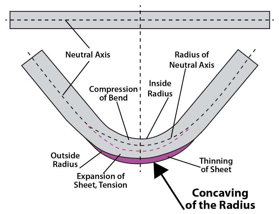
Ito ang talagang nangyayari sa loob ng materyal: kapag inilalapat ang puwersa, ang panlabas na ibabaw ng kurba ay sumisira dahil sa tensile stress habang ang panloob na ibabaw ay sumusuko sa compression. Sa pagitan ng dalawang lugar na ito ay matatagpuan ang neutral axis —isang layer na hindi nasa ilalim ng tension ni compression. Ayon sa Ang Tagagawa , ang mga pwersang pumipigil sa loob ay mas kaunti kaysa sa mga pwersang humihila sa labas, na nagdudulot ng pagtatangkang bumalik ang materyal sa kanyang patag na posisyon.
Ang mga panlabas na hinatak na hibla ay permanente nang nabago (plastic deformation), ngunit ang mga hibla malapit sa neutral axis ay nananatiling nasa kanilang elastic state. Kapag inilabas mo ang pwersang pinaliit, ang mga elastic na hiblang ito ang kumuha ng balik sa likod ng pinaliit—ito ang tinatawag na springback sa aktibo. Ang resulta? Ang iyong metal ay pinaliit sa 88 degrees imbes na sa 90 degrees na ipinrogram mo.
Ang ilang mga salik ang tumutukoy kung gaano kalaki ang springback na makikita mo:
- Uri ng materyal at lakas ng tensile: Ang mga materyales na mas mataas ang lakas ay higit na nagba-back nang agresibo
- Bend Radius: Ang mas malalaking radius ay lumilikha ng napakalaking springback kumpara sa mga mahigpit na pinaliit.
- Kapal ng Materyal: Mahalaga ang ugnayan sa pagitan ng radius at kapal.
- Anggulo ng pagbend: Ang mas matutulis na anggulo ay karaniwang nagbubunga ng mas kaunting springback.
- Direksyon ng Hilatsa: Ang pagpapalit nang perpendicular sa direksyon ng pag-rol ay madalas na nagbibigay ng iba't ibang resulta kumpara sa pagpapalit nang parallel.
Kapag gumagawa ng mga manipis na sheet metal na maaaring ibaluktot, ang 1-sa-1 na ugnayan sa pagitan ng kapal ng materyal at radius ng panloob na baluktot ay karaniwang nagdudulot ng kontroladong springback. Ngunit kung dagdagan ang ratio na ito hanggang 8:1 o mas mataas—na tinatawag na malalim na radius ng baluktot—ang springback ay maaaring lumampas sa 30 hanggang 40 degree.
Mga Estratehiya sa Pagkompensar para sa Iba't Ibang Materyales
Ang pag-alam na mangyayari ang springback ay kalahati lamang ng laban. Ang tunay na kasanayan ay nasa paghahPrognoza kung gaano kalaki ang springback ng bawat materyal—and pagkompensar nang bago pa man hawakan ng punch ang workpiece.
Iba’t iba ang pag-uugali ng springback ng iba’t ibang metal. Narito ang inaasahan kapag binabaluktot ang karaniwang materyales:
- Carbon steel (mild steel): Ang pinakamahuhulaan na materyal. Sa 1-sa-1 na ugnayan ng kapal sa radius, inaasahan ang humigit-kumulang 0.5 hanggang 1 degree na springback. Ang batayang ito ay ginagawang ideal ang carbon steel para sa pag-aaral ng mga teknik sa pagkompensar ng springback.
- Stainless steel (grade 304): Bumabalik nang malaki kumpara sa karaniwang bakal—halos 3.5 na beses na mas malaki. Para sa parehong hugis ng pagkukurba, maaaring makita ang 1.75 degree o higit pa na pagbabalik ng anggulo. Ang pagkukurba ng stainless steel ay nangangailangan ng mas malalaking anggulo ng sobrang pagkukurba at mas agresibong kompensasyon.
- Aluminum (H32 temper): Nasa gitna ng carbon at stainless steel na may humigit-kumulang 3 beses na springback kumpara sa karaniwang bakal. Ang pagkukurba ng aluminum sheet ay nangangailangan ng maingat na pansin dahil ang springback ay sumasali kasama ang pagkakaroon ng materyal na crack sa mga maliit na radius.
- Advanced High-Strength Steels (AHSS) :Ang mga materyal na ito para sa automotive ang nagbibigay ng pinakamalaking hamon. Ayon sa pananaliksik mula sa Center for Precision Forming ng Ohio State University, ang AHSS ay may mas mataas na ratio ng lakas sa ductility, na nagdudulot ng mas malaking springback kumpara sa tradisyonal na bakal dahil sa mataas na yield at tensile strength.
Sobrang Pagkukurba at Real-Time na Koreksyon
Ang pinakasimpleng paraan ng kompensasyon ay ang overbending—ang sinasadyang pagbend sa labas ng iyong target na anggulo upang ang materyal ay bumalik sa ninanais na posisyon dahil sa springback. Kung kailangan mo ng 90-degree na panghuling anggulo at ang iyong materyal ay bumabalik ng 2 degrees dahil sa springback, ibebend mo ito sa 88 degrees (ang bending angle) at ipapabaya mo sa springback ang gawin ang natitira.
Inilalagay ng mga tagagawa ng tooling ang kompensasyong ito sa kanilang mga produkto. Ang karaniwang V-dies na may bukas na sukat na mas maliit sa 0.500 pulgada ay karaniwang pinuputol sa 90 degrees, habang ang mas malalaking dies ay gumagamit ng mas maliit na included angles—88 degrees, 85 degrees, o kahit 73 degrees para sa profound-radius work—upang ipush ang materyal palibot sa punch at kompensahin ang nadagdagang springback.
Ngunit ang mga pagkakaiba sa materyal sa loob ng parehong batch—mga pagbabago sa kapal, direksyon ng ugat, at pagkakaiba sa lakas ng pagtutol sa pagbaba—ay maaari pa ring magdulot ng pagkakamali sa iyong mga anggulo. Dito nagtatagumpay ang mga modernong CNC press brake. Ang mga advanced na makina ay gumagamit ng mga sistema ng pagsukat ng anggulo na may mekanikal na sensor, camera, o laser upang subaybayan ang springback sa workpiece nang real time. Ang mga sistemang ito ay sumusukat sa aktwal na anggulo ng pagkubkob habang ginagawa ang pagbuo at awtomatikong ina-adjust ang lalim ng ram upang makamit ang nakaprogramang resulta—bawat bahagi nang walang kamali-mali, kahit anong pagkakaiba sa materyal.
Para sa mga inhinyero at tagapagawa na naghahanap ng mapagkakatiwalaan at eksaktong resulta, ang pag-unawa sa springback ay hindi opsyonal—ito ay pundamental. Ngunit kahit ang perpektong kompensasyon para sa springback ay hindi makakaligtas sa iyo kung mali ang iyong mga kalkulasyon sa bend radius. Dito pumasok ang K-factor at bend allowance.
Mga Kalkulasyon sa Bend Radius at Mga Pangunahing Prinsipyo ng K-Factor
Nakamaster mo na ang kompensasyon para sa springback—ngunit narito ang isang tanong na nagpapalagay ng mga kahit na eksperyensiyadong tagagawa: bakit laging mali ang sukat ng iyong flat pattern? Karaniwang nanggagaling ang sagot sa dalawang magkaugnay na konsepto: bend radius at K-factor. Ang tamang pagkalkula ng mga ito ang nagtatakda kung ang mga bahagi ay tumpak na magkakasya o magiging mahal na scrap metal. Maging kung ikaw ay nagpoprograma ng CNC press brake o nagse-set up ng sheet metal bending sa SolidWorks, ang mga pundamental na konseptong ito ang tumutukoy sa huling sukat ng iyong bahagi.
Pagkalkula ng Minimum Bend Radius para sa Iyong Materyal
Bawat materyal ay may limitasyon sa pagbend—kung lalampasin mo ito, magkakaroon ng pukos ang workpiece. Ang minimum bend radius ay tumutukoy sa pinakamaliit na kurba na maaari mong likhain nang hindi nababasag ang panlabas na ibabaw ng bend. Ngunit paano mo malalaman ang limitasyong ito para sa iyong tiyak na materyal?
Ang ugnayan ay nakasalalay sa tatlong salik na gumagana nang sabay-sabay:
- Kapal ng Materyal: Ang mas makapal na materyales ay karaniwang nangangailangan ng mas malalaking bend radii upang maiwasan ang pukos
- Ductility: Ang mga mas ductile na materyales (tulad ng karaniwang bakal o tanso) ay kayang magdala ng mas makitid na baluktot kaysa sa mga brittle na materyales
- Temper o kahigpit: Ang mga annealed na materyales ay mas makitid ang baluktot kaysa sa mga work-hardened na bersyon ng parehong alloy
Ang karamihan sa mga gabay sa disenyo ng sheet metal ay nagpapahayag ng minimum bend radius bilang isang ratio sa kapal ng materyal. Halimbawa, ang malambot na aluminum ay maaaring tanggapin ang isang bend radius na katumbas ng 1× kapal nito (isinusulat bilang 1T), samantalang ang mas matitigas na uri ng stainless steel ay maaaring nangangailangan ng 2T o higit pa. Ayon sa Mga gabay sa pagbabaluktot ng Fabworks , ang bend radius ay isang mahalagang parameter na tumutukoy sa minimum na sukat ng baluktot—at ang maling mga halaga ay maaaring magresulta sa hindi inaasahang sukat ng bahagi pagkatapos ng pagbabaluktot.
Narito ang isang praktikal na paraan kapag natututo ka kung paano ibaluktot ang sheet metal: simulan palaging sa mga rekomendasyon ng tagagawa para sa iyong tiyak na alloy at temper. Pagkatapos, i-validate ito gamit ang mga test bend bago isagawa ang produksyon. Ang isang baluktot na tila kasiya-siya ay maaaring mayroon pa ring mikro-cracks na sumisira sa structural integrity nito.
Pag-unawa sa mga Halaga ng K-Factor sa Praktikal na Paggamit
Ngayon ay dumadating ang konsepto na nagpapalito ng higit pang mga inhinyero kaysa sa anumang iba pang aspeto ng trabaho sa sheet metal: ang K-factor. Mukhang kumplikado? Sa katunayan, ito ay diretso na kapag naintindihan mo kung ano ang kinakatawan nito.
Tandaan ang neutral axis mula sa aming talakayan tungkol sa springback—ang imahinasyong linya sa loob ng materyal na hindi sumisira o sumusuko habang binubendahan? Kapag patag ang metal, ang neutral axis na ito ay nasa eksaktong gitna ng kapal ng sheet. Ngunit kapag binubendahan mo ito, may kakaiba nangyayari: ang neutral axis ay lumilipat papunta sa loob ng kurba.
Ang K-factor ay simpleng ratio ng lokasyon ng neutral axis sa kapal ng materyal habang binubendahan. Ito ang nagpapakita kung saan eksaktong nilipat ang neutral line na iyon.
Ayon sa Teknikal na dokumentasyon ng VICLA sa karamihan ng mga kaso, ang neutral na eroplano ay nasa humigit-kumulang isang ikatlo ng kapal mula sa panloob na ibabaw—na nagbibigay ng K-factor na humigit-kumulang 0.33. Gayunpaman, kapag ang ratio ng panloob na radius ng pagkukurba sa kapal ng materyal ay lumampas sa 1 (r/T > 1), ang neutral na aksis ay gumagalaw patungo sa sentro, na nagpapataas ng K-factor.
Ang ilang kadahilanan ang nakaaapekto sa iyong aktwal na halaga ng K-factor:
- Material Type: Iba’t ibang metal ang may iba’t ibang katangian ng elastisidad na nakaaapekto sa posisyon ng neutral na aksis
- Radius ng pagkukurba na nauugnay sa kapal: Ang mas mahigpit na mga kurba ay nagpupush sa neutral na aksis nang mas malalim pa sa loob
- Paraan ng pagbend: Ang air bending, bottom bending, at coining ay may iba’t ibang epekto sa K-factor
- Kondisyon ng materyales: Ang annealed at work-hardened na estado ay nagbabago ng tugon
| Materyal | Karakteristikong Saklaw ng K-factor | Mga Tala |
|---|---|---|
| Malambot na aluminum (5052) | 0.40 – 0.45 | Ang mas mataas na ductility ay nagpapalabas ng neutral na aksis |
| Mild steel (1008–1010) | 0.33 – 0.40 | Pangunahing materyal para sa karamihan ng mga kalkulasyon |
| Stainless steel (304) | 0.30 – 0.35 | Mas mataas na lakas ang nagpapanatili sa neutral axis na mas malapit sa loob |
| Copper and brass | 0.35 – 0.42 | Nag-iiba nang malaki depende sa temper |
Bakit ito mahalaga para sa katiyakan? Ayon sa paliwanag ng Fabworks, ang maling K-factor ay maaaring magdulot ng hindi inaasahang sukat ng bahagi pagkatapos ng pagbend. Ang isang tila maliit na kamalian—tulad ng paggamit ng 0.33 kapag ang aktuwal na pag-uugali ng iyong materyal ay nasa 0.42—ay dumarami sa bawat bend ng iyong bahagi, na maaaring gawing imposible ang pag-aassemble.
Paliwanag sa Bend Allowance at Bend Deduction
Kapag naunawaan na ang K-factor, maaari mo nang harapin ang mga kalkulasyon na direktang tumutukoy sa sukat ng iyong flat patterns. Dalawang pormula ang nangunguna sa katiyakan ng sheet metal bending: ang bend allowance at ang bend deduction.
Bend Allowance kumakatawan sa haba ng arko ng neutral axis sa loob ng bend. Ayon sa Ang teknikal na gabay ng SendCutSend , ito ay nagpapakita kung gaano kalaki ang karagdagang haba na nabubuo dahil sa pagkukurba na nagpapabago sa materyal.
Ang pormula ay:
Bend Allowance = Angle × (π/180) × (Bend Radius + K-Factor × Thickness)
Bawas na pagbabaluktot sumasagot sa praktikal na tanong: gaano kalaki ang dapat mabawasan sa aking patag na pattern upang ang natapos na bahagi ay may tamang sukat? Ito ay kinukwenta bilang:
Bend Deduction = 2 × (Bend Radius + Thickness) × tan(Angle/2) – Bend Allowance
Subukan nating gawin ang isang tunay na halimbawa. Kailangan mo ng bahagi mula sa 0.080" na kapal na 5052 aluminum na may 6" na base at dalawang 2" na flange na may 90-degree na kurba. Sa pamamagitan ng pagtingin sa mga katangian ng materyal, nakita mo ang sumusunod:
- Bend Radius: 0.050"
- K-Factor: 0.43
- Thickness: 0.080"
Kapag ipinasok ang mga halagang ito sa mga pormula, ang resulta ay humigit-kumulang 0.133" na bend allowance at humigit-kumulang 0.127" na bend deduction bawat kurba. Sa halip na i-cut ang 10" na patag na pattern (6" + 2" + 2"), i-cut mo ang humigit-kumulang 9.75"—na kumukuha ng impormasyon sa paglalabas ng materyal (material stretch) na nangyayari habang binubuo.
Mga Praktikal na Gabay para sa mga Inhinyero
Kapag tinutukoy ang mga bahaging may kurba, ang mga gabay sa disenyo ng sheet metal na ito ay makakatipid sa iyo ng mahal na mga pagrerebisa:
- Patunayan ang K-factor nang empirikal: Magputol ng isang test strip, sukatin nang tumpak, isagawa ang isang test bend, pagkatapos ay i-back-calculate ang iyong aktwal na K-factor. Ayon sa rekomendasyon ng VICLA, mas mahalaga ang paghahanap ng isang K-factor na akurat na nagpapahula ng mga dimensyon ng bend sa tunay na mundo kaysa sa paggamit ng mga textbook na halaga.
- Obserbahan ang distortion zone: Ang lugar sa paligid ng bawat bend ay nakakaranas ng malaking dehormasyon. Ayon sa Fabworks, ang mga kritikal na feature tulad ng mga butas o slots ay dapat nasa labas ng rehiyong ito — at ang distortion zone ay umaabot sa parehong direksyon mula sa bend line, hindi lamang sa isang direksyon.
- Isumakop ang mga kinakailangan sa haba ng flange: Bawat kombinasyon ng materyal at kapal ay may minimum na haba ng flange. Kung gagamitin ang mas maikli, may panganib na hindi kumpleto ang mga bend o masira ang tooling.
- Gamitin nang tama ang mga CAD tool: Ang mga software package tulad ng SolidWorks at Autodesk Fusion ay may built-in na sheet metal bend tools. Ilagay ang iyong napatunayang K-factor at mga halaga ng bend radius, at awtomatikong kalkulahin ng software ang mga flat pattern — ngunit ito lang kung ang iyong input na halaga ay sumasalamin sa katotohanan.
Ang tamang pagkuha ng radius ng pagkukurba at ng K-factor ay nagtatatag ng pundasyon na matematikal para sa kahusayan. Ngunit ang mga kalkulasyon lamang ay hindi sapat upang kompensahin ang maling kagamitan. Ang mga punch at die na pinipili mo ay direktang nakaaapekto kung ang mga detalyadong kinalkula mong spesipikasyon ay magreresulta sa mga natapos na bahagi na may tumpak na sukat.
Pagpili ng Tamang Kagamitan para sa Mga Resulta na May Kahusayan
Kinalkula mo na ang iyong K-factor, binigyan mo na ng kompensasyon ang springback, at perpekto mong inprogram ang iyong pagkakasunod-sunod ng pagkukurba—kaya bakit pa rin kulang sa toleransya ang iyong mga bahagi? Madalas, ang salot ay nasa harap mo mismo: ang kagamitan. Ayon sa The Fabricator, bagaman ang mga press brake ay umunlad na bilang mga makina na may maraming axis, mataas na kahusayan, at mga katangian na may sariling pagkakapantay-pantay, ang kagamitan lamang ang tunay na umaapak sa bahagi habang ito ay kinukurba. Ang pagpili ng tamang punch at die ay hindi lamang tungkol sa pagkakasya—ito ang pundasyon ng bawat resulta na may kahusayan na iyong pinaglalaban.
Pagsasama ng Punch at Die sa Iyong mga Kinakailangan sa Kahusayan
Isipin ang iyong metal sheet bender bilang kasing-preciso lamang ng mga kasangkapan na nakainstal dito. Kahit ang pinakamodernong CNC press brake ay hindi makakakompensate para sa mga nasira, hindi tugma, o mali ang sukat na mga tooling. Kaya saan ka dapat magsimula?
Una, isaalang-alang ang tool na pumupuno ng metal sa pinakapangunahing antas: paggawa ng toleransya ng mismong tooling . Para sa mga aplikasyon na nangangailangan ng presisyong pagbend, ang mga tool ay dapat gawin ayon sa toleransya sa loob ng 0.0004-inch na saklaw. Ang antas ng katiyakan na ito ay nag-aalis ng pangangailangan ng shimming o iba pang pag-aadjust habang nasa setup—nakakatipid ng oras at nagpapaguarantee ng pag-uulit ng resulta mula sa unang bahagi hanggang sa huling bahagi.
Bukod sa katiyakan sa paggawa, hanapin ang mga sumusunod na mahahalagang katangian sa iyong mga tool para sa sheet metal bender:
- Mga segmented na seksyon: Ang mga ito ay nagbibigay-daan sa iyo na magbuo ng iba’t ibang haba mula sa ilang pre-cut na piraso, na ginagawang mas ligtas ang paghawak at mas flexible ang mga setup para sa mga komplikadong hugis ng bahagi
- Self-retaining installation: Ang mga tool na nananatili sa posisyon kahit nakaangat ang ram ay nagpapasimple sa paglo-load at nababawasan ang mga error sa setup
- Mga self-seating mechanism: Habang ang presyon ng pagkakapit ay inilalapat, ang mga punch ay dapat mekanikal na umunat papasok sa posisyon—nagtatanggal ng pangangailangan na ilagay ang punch sa ilalim ng die habang nasa setup.
- Kakayahan sa paglo-load mula sa harapan: Ang pag-install ng mga kagamitan mula sa harap ng makina ay nagpapababa nang malaki ng oras ng setup at nagtatanggal ng pangangailangan ng forklift o overhead crane.
- Mga karaniwang taas: Ang mga kagamitan na may parehong taas ay binabawasan ang mga pag-aadjust sa makina sa pagitan ng mga gawain at ginagarantiyahan na ang mga bagong kagamitan ay tugma sa iyong umiiral na koleksyon.
Kapag sinusuri ang kagamitan para sa pagbend ng metal, tandaan na ang mga de-kalidad na press brake tool ay kadalasang ginagawa ayon sa mga pamantayan sa metrik. Ang isang nominal na 0.250-inch na V opening ay talagang 6 mm (0.236 pulgada). Para sa karamihan ng mga gawaing may mataas na kahusayan, ang pagkakaiba na ito ay hindi maaapektuhan ang iyong resulta—ang mga bend sa sheet metal ay may bahagyang elliptical na corner radii, kaya kailangan mo lamang lumapit sa tamang sukat.
Mga Ratio ng V-Die Opening para sa Pinakamahusay na Resulta
Ang bukas ng V-die ay posibleng ang pinakamahalagang desisyon sa pagpili ng kagamitan na gagawin mo. Kung mali ito, walang anumang pag-aadjust sa makina ang makakapagligtas sa iyong kahusayan. Kung tama naman ito, naitatag mo na ang pundasyon para sa mga baluktot na pare-pareho at eksakto.
Ang pamantayan ng industriya ay ang panuntunan ng 8 : ang bukas ng V-die ay dapat humigit-kumulang na 8 beses ang kapal ng materyal. Kaya para sa materyal na may kapal na 0.125 pulgada, pipiliin mo ang bukas ng die na 1 pulgada (0.125 × 8 = 1). Ayon sa mga gabay ng industriya, ang ratio na ito ang nagbibigay ng pinakamahusay na pagganap sa anggulo—tinatawag itong "sweet spot" sa pagpili ng V-die, at ang karamihan sa mga nailathalang chart para sa pagbabaluktot ay nakasentro sa pormulang ito.
Ngunit ang mga gawaing nangangailangan ng mataas na kahusayan ay kadalasang nangangailangan ng mas mahigpit na ratio. Narito ang mga pagbabago:
| Ratio ng V-Die | Aplikasyon | Mga Pag-iisip |
|---|---|---|
| 8 beses ang kapal ng materyal | Pamantayang gawaing nangangailangan ng kahusayan | Pinakamahusay na kahusayan sa anggulo, batayan para sa karamihan ng mga kalkulasyon |
| 6 beses ang kapal ng materyal | Mas maliit na radius, mas maikling mga flange | Kailangan ng mas mataas na tonelada, posible ang mas malapit na toleransya |
| 5× ang kapal ng materyal | Pinakamababang ligtas na ratio | Kung bababa sa halagang ito, may panganib na magkaroon ng mga isyu sa katiyakan ng anggulo at potensyal na pinsala sa kagamitan |
| 10–12× ang kapal ng materyal | Mga aplikasyon na may mas malalaking radius | Binabawasan ang kinakailangang tonelada, ngunit tumataas ang springback at nababawasan ang kontrol sa anggulo |
Kapag ginagawa ang air bending sa mild steel, ang loob na radius ng pagkukurba ay nabubuo nang humigit-kumulang sa 16 porsyento ng bukas na sukat ng V-die. Kaya ang isang die na may sukat na 1 pulgada ay nagbibigay ng humigit-kumulang sa 0.160-pulgadang loob na radius. Kung ang iyong drawing ay nangangailangan ng mas maliit na radius, gamitin ang mas makitid na die—ang isang bukas na sukat na 0.75 pulgada ay nagbibigay ng humigit-kumulang sa 0.120-pulgadang radius.
Huwag kalimutan ang mga limitasyon sa haba ng flange. Ang pinakamababang haba ng flange na maaaring gawin ng isang tiyak na V-die ay humigit-kumulang sa 77 porsyento ng bukas na sukat nito. Ang isang die na may sukat na 1 pulgada ay nangangailangan ng hindi bababa sa 0.77-pulgadang flange. Ang mas maikling flange ay nangangahulugan ng mas makitid na die—ngunit tandaan ang limitasyon ng minimum na ratio na 5×.
Radius ng Punso ng Punch at ang Epekto Nito sa Katiyakan
Bagaman madalas bigyan ng pansin ang pagpili ng V-die, ang radius ng punso ng punch ang direktang nagtatakda sa loob na radius ng pagkukurba ng iyong natapos na bahagi. Para sa mga materyales na may kapal na 0.187 pulgada at mas manipis pa, ang isang acute offset knife punch na may radius na humigit-kumulang sa 0.04 pulgada ay kadalasang sapat para sa karamihan ng mga aplikasyong nangangailangan ng katiyakan. Ang mas makapal na materyales—na may kapal na nasa pagitan ng 0.187 at 0.5 pulgada—ay nangangailangan ng mas malakas na tuwid na punch na may mas malalaking radius—karaniwang humigit-kumulang sa 0.120 pulgada—upang mabigyan ng sapat na suporta ang tumataas na pwersa sa pagbuo.
Sa mga hamon na aplikasyon na kinasasangkutan ng makapal o mataas na tensilye na materyales, ang gawaing metal ay madalas na magkakaroon ng mga paltos o pumuputok kapag ginagamit ang karaniwang mga parameter sa pagkukurba. Ayon sa payo ng The Fabricator, lalo na kapag ang kapal ng materyales ay lumalampas sa 0.5 pulgada, kailangang kumonsulta sa iyong tagapag-suplay ng materyales tungkol sa inirerekomendang mga halaga ng radius ng tip ng punch.
Mga Pag-iisip Tungkol sa Materyales ng Tooling para sa Mga Trabaho na Nangangailangan ng Katiyakan
Ang mga kagamitan para sa pagbuo ng sheet metal ay hindi pantay-pantay. Ang pagpili ng materyales ay direktang nakaaapekto sa buhay ng kagamitan, pagpapanatili ng kahusayan, at kalidad ng ibabaw sa iyong natapos na mga bahagi:
- Mataas na carbon na bakal: Angkop para sa pangkalahatang pagbubuhat ng mga bahagi na may katamtamang dami. Maaaring i-heat-treat upang mapabuti ang kahigpitn, ngunit mas mabilis itong wear under demanding conditions
- Mga hardened tool steels (D2, A2): Ang pamantayan para sa mataas na dami ng gawaing nangangailangan ng kahusayan. Ayon sa pananaliksik sa industriya , ang mga materyales na ito ay nag-aalok ng mataas na kahigpitn at tibay, lalo na epektibo sa mabigat na pagbubuhat at mga kumplikadong hugis
- Tungsten carbide: Ipinagkakaloob lamang para sa pinakamahihirap na aplikasyon—napakataas na kahigpitn at superior na resistance sa wear para sa pagbubuhat ng matitigas na materyales kung saan ang buhay ng kagamitan ay napakahalaga
- Ceramic at carbide coatings: Inilalapat gamit ang PVD o CVD processes, ang mga coating na ito ay nagpapahusay ng kahigpitn ng ibabaw, binabawasan ang friction, at pinalalawig ang buhay ng kagamitan nang hindi binabago ang geometry ng kagamitan
Para sa mga operator na gumagamit ng metal na hand brake o mas magaan na kagamitan, ang karaniwang tool steels ay karaniwang sapat na. Ngunit ang mataas na dami ng produksyon sa CNC press brakes ay nangangailangan ng investisyon sa premium na mga materyales para sa tooling—ang pangmatagalang pagtitipid mula sa mas kaunting pagbabago ng tool at pare-parehong kahusayan ay malaki ang impluwensya kumpara sa unang pagkakaiba sa gastos.
Pagsusuot ng Tooling at Pagbaba ng Kahusayan
Kahit ang pinakamahusay na tooling ay unti-unting susuutin—at ang pagsusuot ay direktang nagpapababa ng iyong kakayahang magbigay ng eksaktong sukat. Ang tanong ay hindi kung susuutin ba ang iyong mga tool, kundi gaano kabilis mo makikita ang pagsusuot bago ito makaapekto sa kalidad ng mga bahagi.
Maging mapagbantay sa mga sumusunod na babalang senyales:
- Pagtaas ng angular deviation: Ang mga bahagi na dati ay sumusunod sa toleransya ay unti-unting lumalabas sa katanggap-tanggap na saklaw
- Mga marka sa ibabaw: Ang mga sugat o impresyon na lumilitaw sa mga ibinend na ibabaw ay nagpapahiwatig ng nasuot na die shoulders o punch tips
- Di-pantay na springback: Ang nasuot na tooling ay nagbabago ng geometry ng contact, kaya’t ang springback ay naging mas di-maasahan
- Mga nakikitang pattern ng pagsusuot: Mga shiny, polished na lugar sa mga working surface o mga rounded na gilid kung saan dati ay may sharp corners
Ayon sa mga dalubhasa sa kagamitan , dapat mong inspeksyunin ang pagkasuot ng dulo ng punch bawat 10,000 na siklo. Kung ang radius ng dulo ay lumampas sa toleransya o kung bumaba ang kalidad ng pagputol, ibalik sa pagpapaliit (regrind) o palitan agad upang maiwasan ang pinsala sa die. Para sa mga aplikasyong nangangailangan ng kahusayan, isaalang-alang ang paggamit ng mga tiyak na set ng kagamitan para sa iba’t ibang pamilya ng materyales—ang mga kagamitan na gumagana nang maayos sa mababang bakal (mild steel) ay maaaring magkabulok o mabasag kapag ginamit sa matitigas na stainless steel.
Ang tamang pagpili ng kagamitan ang nagtatag ng mekanikal na pundasyon para sa kahusayan. Ngunit kahit ang perpektong tugma na mga punch at die ay hindi makakakompensa sa mga ugali ng materyales na nakabase sa uri nito, na lubhang nag-iiba depende sa bawat metal. Ang pag-unawa kung paano tumutugon ang iba’t ibang materyales sa stress ng pagbubukod ang susunod mong hakbang patungo sa konstanteng kahusayan ng resulta.
Ugali ng Pagbubukod na Nakabase sa Materyales at Pinakamahusay na Pamamaraan
Napili mo na ang tamang kagamitan at kinalkula na ang iyong mga allowance sa pagkukurba—ngunit narito ang isang realidad: ang mga kalkulasyong ito ay sumusupposing na ang iyong materyal ay kumikilos nang may paghuhula. Ang totoo? Ang aluminum ay hindi kumukurba tulad ng stainless steel, at ang tanso ay tumutugon nang lubos na iba kaysa sa brass. Bawat metal ay may sariling 'personalidad' sa press brake, at ang pag-unawa sa mga pagkakaiba na ito ang naghihiwalay sa mga tagapagawa ng may kahusayan mula sa mga nangunguna sa mga isyu ng toleransya.
Paano Kumuha ang Iba't Ibang Metal sa Ilalim ng Stress sa Pagkukurba
Kapag ang puwersa ay inaapplyan sa panahon ng pagkukurba ng bakal o pagkukurba ng aluminum, ang natatanging mga katangian ng materyal ang tumutukoy sa lahat—from sa minimum bend radius hanggang sa springback compensation. Tingnan natin nang buo kung ano ang nagpapagana sa bawat karaniwang sheet metal upang kumilos sa paraan na ginagawa nito.
DUKTILIDAD ang una mong konsiderasyon. Ang mas ductile na mga materyales—tulad ng tanso at malambot na aluminyo—ay kayang humawak sa mas mahigpit na bend radii nang hindi nabibitak. Ang mas matigas na mga materyales tulad ng hindi kinakalawang na asero o mga work-hardened alloy ay nangangailangan ng mas banayad na mga kurba upang maiwasan ang pagkabali ng panlabas na ibabaw. Ayon sa mga alituntunin ng Machinery's Handbook, ang ugnayang ito sa pagitan ng ductility at minimum bend radius ang pundasyon ng mga estratehiya sa pagbaluktot na partikular sa materyal.
Lakas sa Pagkabigat ay direktang nakaaapekto sa springback. Ang mga materyales na may mataas na lakas ay nag-iimbak ng higit na elastic energy habang binubuo, na inilalabas bilang angular recovery kapag ang punch ay binalik. Ito ang dahilan kung bakit ang pagkukurba ng stainless steel ay nangangailangan ng mas malaking overbend compensation kaysa sa mild steel—ang parehong geometry ay nagbibigay ng lubhang magkakaibang resulta.
Paggana ng pagpapalakas ay nagdaragdag ng isa pang layer ng kumplikasyon. Ang ilang materyales ay naging mas matigas at higit na mapanghimagsik habang binubuo ang mga ito. Ang stainless steel ay mabilis na nagiging matigas sa paggawa (work-hardens), kaya ang maramihang pagbend sa parehong lugar ay maaaring magdulot ng pukyaw. Ang iba, tulad ng dead-soft copper, ay nananatiling madaling ipabagu-bago sa paulit-ulit na operasyon ng pagbuo.
Paghahambing ng Materyales para sa Presisyong Pagbend
Ito ay isang talahanayan na nagpapakita kung paano gumaganap ang karaniwang sheet metal sa mga mahahalagang kadahilanan na nakaaapekto sa iyong presisyong resulta:
| Materyal | Pinakamaliit na Ratio ng Radius ng Pagbend | Tendency ng Springback | Kahinaan sa Pagkamarka ng Ibabaw | Paggana ng pagpapalakas |
|---|---|---|---|---|
| Mild steel (1008–1010) | 1× kapal | Mababa | Mababa | Pinakamaliit |
| Stainless steel (304) | 1.5–2× ang kapal | Mataas | Katamtamang Mataas | Agresibong |
| Aluminum (5052-H32) | 1–1.5× kapal | Katamtamang Mataas | Mataas | Moderado |
| Tanso (Malambot) | 0.5–1× ang kapal | Mababa | Napakataas | Mababa |
| Brass (70/30) | 1× kapal | Mababa-Katamtaman | Mataas | Moderado |
Pag-aadjust ng Iyong Pamamaraan Para sa Bawat Uri ng Materyales
Ang pagkaalam sa pangkalahatang pag-uugali ay isang bagay—ang paglalapat ng kaalaman na iyon sa iyong tiyak na aplikasyon ang tunay na pinagmulan ng presisyon. Narito kung paano binebend ang aluminum sheet metal, stainless, at iba pang karaniwang materyales nang may tagumpay.
Stainless Steel: Magplano para sa Mas Mataas na Springback at Mas Malalaking Radius
Ang stainless steel ang pinakamahigpit na materyal sa mga aplikasyon ng eksaktong pagkukurba. Engineering guide ng Wevolver ayon sa, ang stainless steel ay nagpapakita ng humigit-kumulang na 3.5 na beses na springback kumpara sa mild steel. Ibig sabihin, ang isang kurba na nangangailangan ng 2° na overbend compensation sa carbon steel ay maaaring mangailangan ng 7° o higit pa sa stainless steel.
Bakit ganito kalaki ang pagkakaiba? Ang mas mataas na yield strength at modulus of elasticity ng stainless steel ay nag-iimbak ng mas maraming elastic energy habang binubuo ito. Kapag pinagsama sa agresibong work hardening, lumilikha ito ng isang materyal na mas napipilitang bumalik kaysa sa anumang iba sa iyong workshop. Ang pagkukurba ng bakal na sheet sa mga grado ng stainless steel ay nangangailangan ng:
- Mas malalaking panloob na radius ng kurba—karaniwang 1.5× hanggang 2× ang kapal ng materyal bilang minimum
- Mas agresibong angle ng overbend upang kompensahin ang springback
- Maingat na pagkakasunod-sunod upang maiwasan ang maramihang kurba sa parehong lugar
- Mga protektibong pelikula o coating upang maiwasan ang surface galling
Aluminum: Iwasan ang Pagkakabitak sa Mga Mahigpit na Radius
Ang pagpapalukot ng aluminum sheet metal ay nagdudulot ng iba't ibang hamon. Bagaman ang aluminum ay kahalos malambot, ito ay madaling sumira sa mga maliit na radius ng pagpapalukot—lalo na sa mas matitigas na temper o kapag pinapalukot nang sektor sa direksyon ng ugat (grain direction). Ayon sa PEKO Precision, ang ductility ng aluminum ay nagpapahintulot ng mas makitid na pagpapalukot kaysa sa stainless steel, ngunit kung ipipilit nang labis, ang mga panlabas na hibla nito ay mababasag.
Paano palukutin ang aluminum sheet nang hindi sumisira:
- Gamitin ang minimum bend radius na hindi bababa sa 1× ang kapal ng materyal para sa mga soft temper, at 2× o higit pa para sa mas matitigas na temper tulad ng T6
- I-orient ang mga pagpapalukot nang perpendicular sa direksyon ng ugat (grain direction) kung posible
- Isaisip ang annealing bago ang pagpapalukot kung hindi maiiwasan ang mga maliit na radius
- Gamitin ang mga polished tooling upang mabawasan ang surface friction at maiwasan ang galling
Ang springback sa aluminum ay nasa gitna ng mild steel at stainless steel—inaasahan ang humigit-kumulang na 3× na angular recovery kumpara sa carbon steel. Dahil dito, mas pasensyoso ang aluminum kaysa sa stainless steel, ngunit kailangan pa rin ng maingat na kompensasyon para sa mga gawaing nangangailangan ng kahusayan.
Tanso at Tansong Pilak: Ingatan ang Kalidad ng Surface ng Hawakan
Ang mga mas malalambot na materyales na ito ay pinakamadaling i-form ngunit pinakamahirap panatilihin ang magandang itsura. Parehong madaling magkaburak-burak ang tanso at tansong pilak—ang mga impresyon mula sa kagamitan, mga guhit, at mga marka mula sa paghawak ay malinaw na nakikita sa natapos na surface. Ayon sa mga pag-aaral sa ugali ng materyales, ang tanso ay nagpapakita ng pinakamababang springback sa mga karaniwang metal, kaya madali ang kontrol sa anggulo.
Para sa presisyong pagbend ng tanso at tansong pilak:
- Gamitin ang mga protektibong pelikula sa pagitan ng kagamitan at workpiece
- Isaisip ang paggamit ng urethane die inserts para sa mga aplikasyong pang-kosmetiko
- Gumamit ng minimal na springback—ang binend mo ay halos ang eksaktong resulta
- Maging alerto sa work hardening sa tansong pilak kung kinakailangan ang maramihang operasyon sa pag-form
Direksyon ng Grain: Ang Nakatagong Variable
Bawat sheet metal ay may direksyon ng butil—ang oryentasyon ng istruktura ng kristal na nabuo habang ginagawa ang proseso ng pag-rol. Ang pagkukurba na se parallel sa direksyon ng butil ay nagpapataas ng panganib ng pagkakabitak, lalo na sa mga materyales na may mas mababang ductility. Ayon sa mga rekomendasyon ng engineering guidelines, dapat kumurba nang perpendicular sa direksyon ng butil upang mabawasan ang panganib ng pagkakabitak at mapabuti ang kalidad ng kurba.
Kung kailan pinakamahalaga ang direksyon ng butil:
- Aluminum sa mas matitigas na temper (H32, T6)
- Stainless steel sa mga kondisyon na naka-work-hardened
- Anumang materyales na binubend sa o malapit sa minimum radius
- Mga bahagi na nangangailangan ng maraming bend sa iba’t ibang oryentasyon
Para sa mga kritikal na aplikasyon, tukuyin ang direksyon ng butil sa iyong mga drawing. Ito ay nag-aaseguro na ang tagapag-suplay ng materyales ay magbibigay ng mga sheet na may tamang oryentasyon para sa iyong layout ng bend.
Paggawa ng Bend sa Steel Plate: Mga Konsiderasyon para sa Mas Makapal na Materyales
Kapag nagtatrabaho sa mas makapal na mga materyales—karaniwang higit sa 3 mm (0.125")—lumalabas ang karagdagang mga kadahilanan. Ang pagpupurol ng bakal na plato ay nangangailangan ng malaki ang toneladang puwersa, at ang ugnayan sa pagitan ng kapal at radius ng pagpupurol ay naging mas mahalaga.
Ayon sa teknikal na mga sanggunian ng Xometry, ang mas makapal na mga sheet ay nangangailangan ng mas malalaking radius ng pagpupurol upang maiwasan ang pagsira dahil ang pagpupurol ay nagdudulot ng tensile at compressive stresses na hindi gaanong kayang abusuhin ng mas makapal na materyales. Dapat din tumaas ang bukas na sukat ng V-die nang proporsyonal—ang pagpapanatili ng '8× rule' ay naging mas mahalaga habang tumataas ang kapal.
Para sa eksaktong paggawa gamit ang mas makapal na materyales:
- Pataasin ang radius ng pagpupurol nang proporsyonal—kakailanganin ang minimum na 2× na kapal para sa karamihan ng carbon steel na higit sa 6 mm
- Gamitin ang mas malawak na bukas na sukat ng V-die at i-verify ang mga kinakailangang tonelada bago isagawa ang pagbuo
- Maglaan ng dagdag na allowance para sa increased springback habang nagbabago ang ratio ng radius sa kapal
- Isaisip ang hot forming para sa napakamakapal na seksyon kung saan ang cold forming ay umaapproach na sa mga limitasyon ng materyales
Ang pag-unawa sa mga ugali na partikular sa materyal ay nagbabago sa iyong paraan mula sa reaktibong paglutas ng problema patungo sa proaktibong kontrol na may kahusayan at presisyon. Ngunit kahit na may perpektong kaalaman sa materyal at na-optimize na mga kagamitan, maaari pa ring mangyari ang mga depekto. Ang maagang pagkilala sa mga problemang ito—at ang pagkakaroon ng kaalaman kung paano maiiwasan ang mga ito—ay nagpapanatili sa iyong mga bahagi sa loob ng tinakdang toleransya at sa mababang porsyento ng mga nabasag o hindi naaayon sa standard.
Paglutas ng Karaniwang mga Depekto at mga Paraan ng Kontrol sa Kalidad
Na-optimize mo na ang iyong mga kagamitan, kinalkula mo na ang iyong mga allowance sa pagbend, at isinama mo na ang ugali ng materyal—ngunit lumilitaw pa rin ang mga depektibong bahagi. Pamilyar ba ito sa iyo? Kahit ang mga ekspertong tagapagawa ay nakakaranas pa rin ng cracking, wrinkling, at mga error sa dimensyon na sumisira sa mga layuning presisyon. Ang pagkakaiba sa pagitan ng mga workshop na nahihirapan at ng mga nangunguna ay nasa sistematikong paglutas ng problema: mabilis na pagkilala sa mga pangunahing sanhi at pagpapatupad ng mga solusyon na tumatagal. Ang pag-unawa kung paano bumbalin ang metal nang matagumpay ay nangangahulugan ng pagkilala kung kailan may mali at alam kung ano ang dapat i-adjust.
Paggawa ng Mga Hakbang upang Maiwasan ang Cracks at Pinsala sa Ibabaw
Ang pagsira o cracking ay marahil ang pinakapanghihinaan ng loob na depekto dahil madalas itong nangangahulugan ng mga nasirang bahagi na walang paraan para maibalik. Ngunit ang mga pagsira ay hindi lumalabas nang kusa—sila ay sumusunod sa mga nakaplanong pattern na nagpapakita ng kanilang mga sanhi.
Ayon sa pagsusuri ng The Fabricator sa mga pagkabigo ng pagbaluktot, ang kalidad ng materyal ay kadalasang nakakatulong sa mga isyu ng pagbibitak. Ang mga materyal na mababa ang kalidad na may mga inklusyon, void, o hindi pare-parehong microstructure ay maaaring mabali sa ilalim ng stress sa pagbaluktot—kahit na tama ang mga parameter ng iyong proseso. Ang mahina at murang materyal ay walang lugar sa paggawa ng mga de-kalidad at walang pagkakamaling bahagi.
Karaniwang mga sanhi ng pagkakabit at ang kanilang mga solusyon:
- Masyadong masikip ang radius ng buhol: Ang panlabas na ibabaw ay sumisira nang lampas sa limitasyon ng paglalawig ng materyales. Solusyon: Palawakin ang radius ng panloob na baluktot hanggang sa kahit na ang minimum na sukat para sa iyong materyales at kapal
- Pagbubuhat na separallel sa butil: Ang direksyon ng pag-rol ay lumilikha ng direksyonal na kahinaan. Solusyon: I-reorient ang mga bahagi upang ang mga baluktot ay tumakbo nang perpendicular sa butil
- Mga depekto sa materyales: Ang mga kabilang na sangkap tulad ng manganese sulfide ay lumilikha ng mga punto ng pagsisipol ng stress. Solusyon: Kumuha ng materyal na may mas mataas na kalidad at i-verify ang mga sertipiko
- Pagsisigla sa Pamamagitan ng Pagpapalakas Ang mga nakaraang operasyon sa pagbuo ay nagpabaga sa materyal. Solusyon: Ilagay sa annealing sa pagitan ng mga operasyon o baguhin ang disenyo upang mabawasan ang kabuuang strain
- Labis na presyon sa coining: Ang labis na presyon ay sumisira sa integridad ng materyal. Solusyon: Lumipat sa air forming, na nagdudulot ng mas kaunting pinsala sa bahagi
Ang pinsala sa ibabaw—tulad ng mga sugat, mga marka ng die, at galling—ay nagmumula sa iba't ibang pangunahing sanhi. Ang mga marka ng die sa panlabas na ibabaw ay karaniwang nangangahulugan ng coining na may labis na presyon o isang bukas na die na sobrang maliit para sa kapal ng iyong materyal. Ayon sa mga eksperto sa industriya, ang mga markang ito ay lumilitaw kapag inilalapat ang sobrang presyon sa sobrang maliit na lugar.
Pag-alis ng Wrinkling at mga Kamalian sa Sukat
Kahit ang pagkakahati ay nakaaapekto sa panlabas na ibabaw ng kurba, ang pagkakarumpondo ay nangyayari sa loob na radius kung saan ang materyal ay napipiga habang binubuo. Ang mga pagkakamali sa sukat—mga bahagi na may maling sukat o anggulo—ay madalas na sanhi ng mga variable sa proseso kaysa sa mga isyu sa materyal.
Paano mo binitin ang metal nang hindi lumulumpondo? Simulan sa pamamagitan ng pag-unawa sa mekanika ng piga:
- Pagkakarumpondo sa loob na radius: Ang hindi sapat na suporta sa materyal habang binubuo ay nagpapahintulot sa pagkabuko. Solusyon: Gamitin ang radius ng ilong ng punch na mas malapit sa iyong target na loob na radius, o lumipat sa bottom bending para sa mas mahusay na kontrol sa materyal
- Distorsyon ng flange: Ang materyal ay dumadaloy nang di pantay habang binubuo. Solusyon: I-verify ang ratio ng bukas na die at tiyaking pare-pareho ang kapal ng materyal
Ang mga pagkakamali sa sukat ay nangangailangan ng sistematikong diagnosis:
- Pagkakaiba sa anggulo mula sa target: Ang mga bahagi ay palaging lumalampas o kulang sa programadong anggulo. Suriin ang mga setting ng springback compensation, i-verify kung ang mga katangian ng materyal ay sumasang-ayon sa mga ipinagpalagay sa iyong programa, at suriin ang tooling para sa pagsuot
- Di pare-parehong haba ng flange: Mga pagkakamali sa posisyon ng backgauge o pag-agap ng materyal habang binubuo. I-verify ang kalibrasyon ng backgauge at tiyaking angkop ang suporta sa materyal
- Kumulatibong pag-accumulate ng toleransya: Ang maraming pagkukurba ay nagpapalala sa mga maliit na pagkakamali. I-recalculate ang K-factor gamit ang aktuwal na pagsusuri sa mga kurba imbes na ang teoretikal na mga halaga
Ang Diagnostikong Pamamaraan sa Pagsusuri ng Pangunahing Sanhi
Kapag hindi natutugunan ang mga layuning may katiyakan, iwasan ang pag-aadjust nang pabagu-bago. Sa halip, sundin ang sistematikong proseso ng pagtukoy sa problema:
- I-segregate ang variable: Pangkalahatan ba ang problema sa lahat ng bahagi, o pansamantala lamang? Ang pangkalahatang isyu ay sumusugod sa setup o sa tooling; ang pansamantalang problema ay nagsusugod sa pagkakaiba-iba ng materyal
- Suriin muna ang mga obvio: I-verify kung ang sertipiko ng materyal ay tugma sa inyong mga pagpapalagay sa programming. Kumpirmahin kung ang tooling ay hindi nasira o napalitan
- Sukatin ang aktuwal laban sa inaasahan: Gamitin ang mga instrumentong may kahusayan upang sukatin ang pagkakaiba—ang paghuhula ay nagdudulot ng labis na pag-aayos
- Baguhin ang isang variable nang paisa-isa: Ang pag-aayos ng maraming parameter nang sabay-sabay ay nagiging imposible ang pagkilala sa tunay na ugat na sanhi
- I-record ang mga paraan na epektibo: Kapag nalutas mo na ang problema, i-record ang solusyon para sa hinaharap na sanggunian
Ang kasanayan ng operator ay direktang nakaaapekto sa kahusayan ng mga resulta. Ang mga eksperyensyadong operator ay nakikilala ang mga banayad na pagkakaiba—ang materyal na pakiramdam ay iba, tunog ay iba kapag hinampas, o kaya’y hindi inaasahan ang pag-uugali nito habang sinusubukan ang mga baluktot. Ang elemento ng tao na ito, ayon sa pagsusuri ng industriya, ay nagpapalakas sa kahusayan ng makina imbes na palitan ito.
Mga Punto ng Pagsubok sa Kalidad at Paraan ng Pagsusuri
Ang maagang pagkakakita ng mga depekto ay nagpipigil sa pag-akumula ng mga sirang produkto. Ilapat ang mga puntong ito sa buong proseso ng pagbabaluktot ng sheet metal:
- Pagsisiyasat sa unang piraso: Suriin nang lubusan ang unang bahagi bago simulan ang produksyon. Sukatin ang lahat ng mahahalagang sukat at anggulo
- Pagsusuring panggitna (In-process sampling): Suriin ang mga bahagi sa regular na mga panahon—bawat ika-10, ika-25, o ika-50 na piraso depende sa kahalagahan ng toleransya
- Pagsubaybay sa pagkasira ng tool: Ayon sa mga eksperto sa press brake, ang pagsubaybay sa loob na radius ng pagkukurba sa paglipas ng panahon ay nagbibigay ng mahusay na sukatan para sa pagsusuri ng kalusugan ng mga kagamitan
Para sa pagpapatunay ng katiyakan, pumili ng mga pamamaraan sa pagsusuri na naaangkop sa iyong mga kinakailangan sa toleransya:
- Protraktor at mga sukatan ng anggulo: Ayon sa mga eksperto sa pagsusukat , ang tradisyonal na vernier protractor ay nagbibigay ng katiyakan hanggang sa humigit-kumulang ±0.5°—sapat para sa pangkalahatang gawain ngunit hindi sapat para sa mga aplikasyong may mabibigat na toleransya
- Mga digital na sukatan ng anggulo: Ang mga device tulad ng Angle Meister ay nagbibigay ng katiyakan na ±0.1°, na nagpapahintulot ng tiyak na pagsukat ng springback at detalyadong pagkuha ng datos para sa SPC
- Mga go/no-go fixture: Para sa mataas na dami ng produksyon, ang mga simpleng check fixture ay nag-aalok ng mabilis at maaasahang pagpapatunay—kung ang bahagi ay napapasok sa fixture, ang mga anggulo ng pagkukurba at buong profile nito ay nasa loob ng toleransya
- Coordinate Measuring Machines (CMM): Ayon sa mga eksperto sa pagsusuri, ang CMM ay sinusuri ang mga anggulo ng pagkukurba kasama ang buong profile ng bahagi, na nagbibigay ng komprehensibong datos para sa mga kritikal na aplikasyon
Ang pagpili ng tamang paraan ng pagsusuri ay nangangahulugan ng balanse sa badyet, detalye ng kailangang datos, at oras na magagamit para sa pagpapatunay. Para sa karamihan ng mga operasyon sa presisyong pagkukurba ng manipis na metal, ang kombinasyon ng digital na pagsukat ng anggulo para sa kontrol ng proseso at mga check fixture para sa pagpapatunay sa produksyon ang nagbibigay ng pinakamahusay na resulta.
Kapag mayroon nang mga sistema para sa pag-iwas sa depekto at kontrol sa kalidad, handa ka nang palawakin ang presisyon mula sa prototype hanggang sa buong produksyon. Ang pagpapanatili ng mahigpit na toleransya sa libo-libong bahagi ay nangangailangan ng karagdagang kontrol sa proseso—at madalas, ng tamang kasosyo sa pagmamanupaktura.
Pagkamit ng Pare-parehong Presisyon sa mga Kapaligiran ng Produksyon
Nakamaster mo na ang mga pundamental—kompensasyon sa springback, kalkulasyon ng K-factor, pagpili ng mga kagamitan, at pag-iwas sa mga depekto. Ngunit narito ang tunay na pagsusulit: kayang panatilihin mo ba ang mga pamantayan ng kahusayan na iyon kapag dumadami mula sa isang prototype hanggang sa libo-libong bahagi para sa produksyon? Ang transisyon mula sa pagbubuklat ng prototype patungo sa mass production ang lugar kung saan maraming mga tagapagawa ang nababagay. Ang paraan na gumagana para sa sampung bahagi ay hindi awtomatikong magiging epektibo para sa sampung libong bahagi. Ang pag-unawa kung paano ibuklat ang metal nang pare-pareho sa dami ng produksyon ay nangangailangan ng ibang paraan ng pag-iisip—isang paraan na itinatayo sa kontrol sa proseso, awtomasyon, at sistematikong pagpapatunay.
Mula sa Prototype hanggang sa Kahusayang Handa na para sa Produksyon
Ang prototyping ay may mahalagang layunin na higit pa sa simpleng paggawa ng isang sample na bahagi. Ayon sa gabay sa Prototyping ng xTool ang isang prototype ay kumakatawan sa aktwal na pisikal na tugon ng disenyo sa ilalim ng mga kondisyon ng pagmamanupaktura—ito ang iyong checkpoint bago magpasya sa buong produksyon. Kung ito ay tumutugon sa lahat ng mga kinakailangan, dadalhin pa ang disenyo. Kung nabigo ito, mura pa ang mga pagbabago sa yugtong ito.
Kung paano nga ba ang wastong pagbubukod ng sheet metal sa yugtong prototype habang inihahanda mo rin ang sarili para sa tagumpay ng produksyon? Ipaunang-pansin ang mga sumusunod na priyoridad sa pagpapatunay:
- Patunayan ang kakayahang pang-produksyon: Ang paggawa ng isang prototype ay nagpapakilos sa iyo na pagsagupin ang eksaktong proseso ng sheet metal na kailangan para sa bawat tampok. Ito ang nagpapakita kung ang mga radius ng pagbubukod ay realistiko o kung ang disenyo ay nangangailangan ng mga operasyon na magpabagal sa produksyon
- Kumpirmahin ang pag-uugali ng materyal: Subukan ang mga pagbubukod gamit ang tunay na materyal na gagamitin sa produksyon—hindi lamang ang katulad na stock. Ang mga pagkakaiba ng materyal mula sa iba’t ibang supplier ay maaaring malaki ang epekto sa springback at kalidad ng pagbubukod
- Patunayan ang pagpili ng mga tool: Ang mga pagsubok sa prototype ay nagpapatunay na ang iyong mga kombinasyon ng punch at die ay nakakaproduk ng inaasahang resulta bago ka pa man lubos na nakakabit sa produksyon ng mga tooling
- Itakda ang mga parameter ng proseso: Idokumento ang bawat setting na nakakaproduk ng mga bahagi na sumusunod sa pamantayan—ang mga ito ang magiging iyong batayan sa produksyon
Ang agwat sa pagitan ng tagumpay ng prototype at ng pagkakasunod-sunod sa produksyon ay madalas na nababase sa isang kadahilanan: ang pagkakaiba-iba. Ang isang solong prototype ay gumagamit ng isang piraso ng materyales, isang hanay ng kondisyon ng tooling, at ang teknik ng isang operator lamang. Sa produksyon, lumilitaw ang pagkakaiba-iba sa lahat ng tatlong aspetong ito—at ang iyong proseso ay kailangang makalunok ng pagkakaiba-ibang ito habang pinapanatili ang toleransya.
Mga Kakayahan ng CNC Press Brake para sa Presisyong Produksyon
Ang mga modernong makina para sa pagbend ng metal sheet ay umunlad nang tiyak upang tugunan ang pagkakaiba-iba sa produksyon. Ayon sa Valley Metal Works , ang mga CNC hydraulic press brake ay nagbibigay ng di-maihahambaling katiyakan sa pamamagitan ng pagpapanatili ng mahigpit na toleransya sa bawat bahaging nalilikha—maging isang solong prototype man o isang mataas na dami ng produksyon.
Tatlong teknolohiya ang nagpapadali ng konsistensyang ito:
Mga sistemang pagsukat ng anggulo sa real-time gumagamit ng mga sensor, laser, o kamera upang subaybayan ang aktwal na anggulo ng pagkubkob habang ginagawa ang pagbuo. Sa halip na umaasa lamang sa mga nakaprogramang posisyon ng ram, sinusukat ng mga sistemang ito ang aktwal na nangyayari sa workpiece. Kapag ang pagkakaiba-iba ng materyal ay nagdudulot ng springback na lumalabas sa inaasahang mga halaga, awtomatikong ina-adjust ng sistema ang lalim ng ram upang makamit ang nakaprogramang resulta—bawat bahagi nang sunud-sunod.
Awtomatikong kompensasyon para sa crowning ay tumutugon sa isa pang hamon sa produksyon: ang deflection sa buong haba ng bed. Kapag kinukurba ang mahabang bahagi, ang ram at bed ng press brake ay natural na nalalabas (deflect) dahil sa beban, na nagreresulta sa mas matalas na kurba sa gitna kaysa sa mga gilid. Ang mga CNC-kontroladong crowning system ay awtomatikong nag-a-adjust upang kontrahin ang deflection na ito, na nagpapanatili ng pare-parehong anggulo sa buong haba ng kurba.
Optimisasyon ng programa nag-iimbak ng mga na-verify na sequence ng pagkukurba, mga setting ng tonelada, at mga halaga ng kompensasyon para sa agarang pagkuha. Kapag na-tune na ang isang bahagi sa panahon ng pagsusuri ng prototype, ang mga parameter na iyon ay naililipat nang direkta sa produksyon nang walang kailangang muling matuto. Ang isang makina para sa pagkukurba ng bakal na may matibay na pamamahala ng programa ay nagtatanggal ng mga pagkakaiba sa pag-setup na nagdudulot ng mga problema sa unang piraso.
Ang mga kakayahan na ito ay hindi pinalalitan ang kasanayan ng operator—pinapalakas lamang nito ang kasanayan nito. Ayon sa pagsusuri ng industriya, ang awtomasyon ng CNC ay nagtatanggal ng mga kamalian na ginagawa ng tao habang tiyak na ang bawat bahagi ay sumusunod sa eksaktong mga espesipikasyon.
Pagpapalawak ng Kalidad sa Mga Mataas na Damit ng Produksyon
Ang mataas na dami ng produksyon ay nagdudulot ng mga hamon na simpleng hindi umiiral sa trabaho sa prototype. Umiinit ang mga tool. Nagbabago ang mga batch ng materyales. Nagbabago ang mga operator sa bawat shift. Nagbabago ang temperatura ng kapaligiran. Ang bawat variable na ito ay bahagyang nagpapalapit o nagpapalayo sa proseso mo mula sa mga limitasyon ng toleransya.
Ang matagumpay na presisyong pagkukurba sa mataas na dami ng produksyon ay nangangailangan ng sistematikong kontrol sa proseso:
- Statistical Process Control (SPC): Subaybayan ang mga mahahalagang sukat sa buong produksyon upang matukoy ang mga trend bago pa man maging mga depekto. Ang unti-unting pagkiling ng anggulo ay nagpapahiwatig ng pagsusuot ng mga kagamitan; ang biglang pagbabago naman ay tumutukoy sa pagbabago ng materyales o ng pag-setup.
- Pamamahala ng mga lot ng materyales: Subukan ang pagbend sa mga sample mula sa bawat bagong lot ng materyales at i-adjust ang kompensasyon para sa springback kung kinakailangan. Ang dalawang coil na may parehong sertipiko ay maaaring mag-asal nang iba-iba sa ilalim ng stress sa pagbuo.
- Mga iskedyul para sa pag-ikot ng mga kagamitan: Itigil at i-regrind ang mga kagamitan batay sa bilang ng mga cycle, hindi sa nakikitang pagsusuot. Ang paghihintay hanggang lumitaw ang mga problema sa kalidad ay nangangahulugan na ang mga scrap ay nabuo na.
- Mga kontrol sa kapaligiran: Nakaaapekto ang temperatura sa parehong mga katangian ng materyales at sa kalibrasyon ng makina. Ang mga lugar ng produksyon na may kontroladong klima ay inaalis ang isa pang variable mula sa iyong equation ng katiyakan.
Ang Mahalagang Papel ng DFM Support
Ito ay isang katotohanan na madalas na binabalewalain ng maraming inhinyero: ang pinakamadaling pagtaas ng katiyakan ay kadalasang nangyayari bago pa man ibentil ang anumang metal. Ang pagsusuri sa Design for Manufacturability (DFM) ay nakikilala ang mga oportunidad para pasimplehin ang produksyon habang panatilihin — o kahit paunlarin — ang mga resulta ng katiyakan.
Ayon sa Dalsin Industries, ang DFM ay nangangahulugan ng pagdidisenyo o pag-iingenyero ng isang produkto upang lubos na mapadali ang proseso ng pagmamanupaktura. Kasama sa mga benepisyo nito ang pagbawas ng gastos, pati na rin ang maagang pagkilala at paglutas ng mga problema sa yugto ng disenyo—na siyang pinakamurang lugar para tugunan ang mga hamon.
Ang epektibong suporta sa DFM para sa presisyong pagkukurba ay sumasaklaw sa mga sumusunod:
- Rasyonalisasyon ng toleransya: Lahat ba ng tinukoy na toleransya ay talagang kinakailangan para sa pagganap? Ang pagpapaluwak sa mga hindi kritikal na sukat ay nagpapababa ng gastos nang hindi nakakompromiso sa pagganap.
- Optimisasyon ng tampok: Maaari bang i-reorder ang pagkakasunod-sunod ng mga kurba upang mapabuti ang access at mabawasan ang kabuuang error? Minsan, ang isang maliit na pagbabago sa disenyo ay lubos na nakakawala ng isang kumplikadong setup.
- Pagpapabuti ng pagpili ng materyales: Magbibigay-ba ang ibang alloy o temper ng parehong pagganap ngunit may mas mahusay na kakayahang pormain at pagkakasunod-sunod?
- Pamantayan sa mga kagamitan sa pagpoproseso: Maaari bang i-adjust ang mga katangian upang gamitin ang pamantayang kagamitan imbes na mga pasadyang punch at die?
Para sa mga aplikasyon sa automotive kung saan ang kahusayan ay hindi pwedeng ipagkait, ang mga tagagawa na may sertipiko ng IATF 16949 ay nagpapakita ng mga sistema ng pamamahala ng kalidad na kinakailangan para sa pare-parehong produksyon. Ang pamantayan sa kalidad para sa automotive na ito ay nangangailangan ng naidokumentong kontrol sa proseso, pagsusuri sa sistema ng pagsukat, at mga protokol para sa patuloy na pagpapabuti—nang eksaktong tumutugon sa pangangailangan upang mapanatili ang matalas na toleransya sa buong dami ng produksyon. Ang mga kumpanya tulad ng Shaoyi (Ningbo) Metal Technology ay nagkakasama ang mga sistemang pangkalidad na sertipikado ng IATF 16949 at ang komprehensibong suporta sa DFM, na tumutulong sa mga inhinyero na i-optimize ang mga disenyo para sa kakayahang gawin bago pa man isagawa ang komitmento sa produksyon.
Isang Workflow sa Produksyon na Nakatuon sa Kahusayan
Kahit na gumagawa ka man ng mga bahagi ng chasis, mga bracket ng suspension, o mga struktural na assembly, ang sistematikong workflow na ito ay nananatiling eksakto mula sa konsepto hanggang sa paghahatid:
- Pagtukoy sa Kagawusan: Itakda ang mga espesipikasyon ng toleransya batay sa mga pangangailangan sa pagganap. I-dokumento kung aling mga sukat ang kritikal sa pagganap at alin ang may kakayahang umangkop
- Pagpili ng materyal: Pumili ng mga materyales na may balanseng pagkabuo, lakas, at gastos. I-verify ang kakayahan ng mga tagapag-suplay para sa pare-parehong katangian mula sa bawat batch
- Pagpili ng paraan: I-akma ang paraan ng pagpiyok (air bending, bottom bending, o coining) sa mga kinakailangan sa toleransiya at inaasahang dami ng produksyon
- Tungkol sa mga tool: Pumili o idisenyo ang mga tool na nakakamit ang target na radius at anggulo kasama ang sapat na buhay na pagkakaubos para sa dami ng produksyon
- Pagpapatibay sa Proseso: Gumawa ng mga prototype gamit ang mga materyales, tool, at kagamitan na may layuning gamitin sa produksyon. I-verify ang lahat ng sukat bago ipalabas ang produkto para sa produksyon
Ang mga kakayahan sa mabilis na paggawa ng prototype ay pabilisin nang malaki ang daloy ng gawaing ito. Sa halip na maghintay ng ilang linggo para sa mga prototype tool, ang mga tagagawa na nag-aalok ng mabilis na paggawa ng prototype sa loob ng 5 araw ay nagbibigay-daan sa mga inhinyero na mabilis na i-verify ang mga kinakailangan sa katiyakan—na maaaring subukan ang maraming bersyon kung kinakailangan bago pa man isakatuparan ang produksyon. Ang ganoong bilis ay lalo pang kapaki-pakinabang kapag nagpapaunlad ng mga bagong komponente kung saan ang pag-uugali sa pagpiyok ay hindi lubos na mahuhulaan mula sa mga kalkulasyon lamang.
Ang mga desisyon sa inhinyerya ng sheet metal na ginagawa mo habang binubuo ang proseso ay tumutukoy sa mga resulta ng iyong produksyon. Ang pag-invest ng oras sa sistematikong pagpapatunay—sa halip na mabilis na pumunta sa produksyon—ay nagpapigil sa mga isyu sa kalidad na kumakain ng mas maraming resources upang ma-resolve pagkatapos ng pangyayari.
Kapag na-verify na ang iyong proseso ng produksyon at naka-istablish na ang mga sistema ng kalidad, isang tanong lamang ang natitira: paano mo pipiliin ang tamang kasosyo sa pagmamanupaktura upang maisagawa ang iyong mga kinakailangan sa presisyong pagkukurba? Ang sagot ay nagsasangkot ng pagsusuri sa mga kakayahan, sertipikasyon, at serbisyo ng suporta na direktang nakaaapekto sa iyong mga resulta.
Pipiliin ang Tamang Kasosyo para sa Iyong mga Pangangailangan sa Presisyong Pagkukurba
Nasipsip mo na ang mga pangunahing teknikal—kompensasyon sa pagbabalik ng hugis (springback), mga kalkulasyon ng K-factor, optimisasyon ng mga kagamitan, at mga estratehiya na nakabase sa uri ng materyales. Ngunit narito ang praktikal na katotohanan: ang karamihan sa mga inhinyero at developer ng produkto ay hindi nagpapaganap ng eksaktong pagkuha ng hugis ng metal sa loob ng kanilang sariling pasilidad. Sila ay nagsasama-sama sa mga espesyalisadong tagapagawa na binabago ang mga teknikal na tukoy (specifications) sa mga natapos na bahagi. Ang pagpili ng maling kasosyo ay magdudulot ng kabiguan sa pagtugma sa toleransya, pagkakaligtaan ng mga takdang panahon, at paglabag sa badyet. Samantala, ang pagpili ng tamang kasosyo ay nagpapabago sa iyong mga disenyo upang maging tunay at maaasahang produksyon.
Paano nga ba hinuhusgahan ang mga potensyal na kasosyo sa pagmamanupaktura? Kung kailangan mo man ng pagkuha ng hugis ng aluminium sheet para sa mga mabaga at protektibong kahon o ng pagkuha ng hugis ng metal profile para sa mga istruktural na bahagi, ang mga pamantayan sa pagpili ay nananatiling pareho. Subukan nating i-sintesis ang lahat ng tinalakay sa artikulong ito sa isang konkretong balangkas na maaaring gamitin.
Pagbuo ng Iyong Teknikal na Tukoy sa Eksaktong Pagkuha ng Hugis
Bago makipag-ugnayan sa anumang fabricator, dokumentuhin nang malinaw ang iyong mga kinakailangan. Ang hindi malinaw na mga teknikal na detalye ay nagdudulot ng maling pagtutuos, maling komunikasyon, at mga bahagi na hindi sumasapat sa inaasahan. Ang isang maayos na istrukturang teknikal na detalye ang nagsisilbing pundasyon para sa tumpak na mga pagtutuos at matagumpay na resulta.
Ang iyong teknikal na detalye para sa precision bending ay dapat kasama ang sumusunod:
- Mga kinakailangan sa tolerance: Tukuyin ang mga toleransya sa anggulo (±0.5°, ±0.25°, o mas mahigpit pa) at mga toleransya sa sukat para sa mga kritikal na katangian. Ihiwalay ang mga sukat na kritikal sa pagganap mula sa mga sukat na may kakayahang umangkop
- Mga detalye ng materyal: Tukuyin ang uri ng alloy, temper, kapal, at anumang mga kinakailangan sa direksyon ng butil. Isama ang mga alternatibong tinatanggap kung may kakayahang umangkop
- Mga kinakailangan sa tapusin ng ibabaw: Dokumentuhin ang mga antas ng pagmamarka na tinatanggap, ang pangangailangan sa protektibong pelikula, at anumang mga pamantayan sa panlabas na anyo
- Inaasahang Damí: Tukuyin ang dami ng mga prototype, unang produksyon, at ang inaasahang taunang dami. Ito ay nakaaapekto sa mga desisyon tungkol sa tooling at sa istruktura ng presyo
- Mga kinakailangan sa pagsusuri at inspeksyon: Tukuyin kung anong mga sukat ang kailangan, ang mga tinatanggap na paraan ng inspeksyon, at ang mga inaasahang dokumentasyon
Ayon sa pananaliksik sa industriya tungkol sa pagpili ng mga tagapag-suplay, ang pagbigay ng tumpak na mga drawing sa engineering na nagtutukoy ng materyales, kapal, anggulo ng pagkurbang, at toleransya—kasama ang dami ng batch, huling pangwakas ng ibabaw, at espesyal na mga kinakailangan—ay nagpapahintulot sa mga tagapag-suplay na lubos na isaalang-alang ang gastos at kumplikasyon ng proseso, na maiiwasan ang dagdag na gastos sa susunod.
Ano ang Dapat Hanapin sa isang Kasamang Tagapag-bend ng Presisyon
Kapag kumpleto na ang iyong mga teknikal na tukoy, suriin ang mga potensyal na kasosyo batay sa mga sumusunod na mahahalagang pamantayan. Ang pinakamahusay na mga tagapag-gawa ay nakakapag-ubos ng mataas na antas sa maraming aspeto—hindi lamang sa pinakamababang presyo.
Mga Kakayahan sa Toleransya at Kalidad ng Kagamitan
Kaya bang abutin ng tagapag-gawa ang iyong kinakailangang mga toleransya? Hindi ito tungkol sa mga pahayag sa isang website—kundi sa ipinakita nang tunay na kakayahan. Ayon sa mga eksperto sa paggawa, ang modernong CNC press brakes ay kayang panatilihin ang katiyakan sa anggulo ng pagkurbang sa loob ng ±0.5° o mas mainam pa, kasama ang katiyakan sa posisyon ng dimensyon sa loob ng ±0.1 mm. Ito ay nakasalalay sa pag-uulit ng kagamitan, kakayahan sa kompensasyon para sa springback, at kalidad ng operator.
Kapag sinusuri ang mga kakayahan ng kagamitan, isaalang-alang ang mga sumusunod:
- Teknolohiya ng press brake: Ang mga CNC machine na may mga sistema ng real-time na pagsukat ng anggulo ay mas mahusay kaysa sa mga manu-manong kagamitan o lumang kagamitan para sa mga gawaing nangangailangan ng kahusayan
- Aklatan ng kagamitan: Ang isang komprehensibong imbentaryo ng mga tool ay nagpapadali ng optimal na pagpili ng punch at die nang walang mga pagkaantala dahil sa custom na tooling
- Mga sistema ng pagsukat: Ang pagsusuri ng anggulo habang ginagawa ang proseso at ang mga kakayahan ng CMM ay nagpapakita ng dedikasyon sa mga resulta na may mataas na antas ng kahusayan
Mga Sertipiko sa Kalidad at mga Sistema ng Pamamahala
Ang mga sertipiko ay nagbibigay ng ikatlong panig na pagpapatunay na ang mga sistemang pangkalidad ng isang tagagawa ay sumusunod sa mga kinikilalang pamantayan. Para sa mga aplikasyon ng presisyong metal bending, hanapin ang mga sumusunod:
- ISO 9001: Ang pangunahing pamantayan sa pamamahala ng kalidad na nagpapakita ng pagkakapantay-pantay ng proseso at patuloy na pagpapabuti
- IATF 16949: Ang pamantayan sa kalidad ng industriya ng automotive, na umaabot pa sa ibabaw ng ISO 9001 upang matiyak ang pagsunod sa lean manufacturing, pag-iwas sa depekto, pagpigil sa pagkakaiba-iba, at pagbawas ng basura. Ang sertipikasyong ito ay nagpapahiwatig ng kakayahang gumawa ng mga aplikasyong nangangailangan ng pinakamataas na antas ng kahusayan
- Mga nasusulat na protokol sa inspeksyon: Higit sa mga sertipiko, unawain ang kanilang aktwal na proseso ng pagkontrol sa kalidad—inspeksyon ng unang piraso, sampling habang ginagawa ang proseso, at mga prosedurang panghuling pagpapatunay
Ayon sa mga eksperto sa pamamahala ng kalidad, ang sertipikasyon sa IATF 16949 ay nagbibigay ng pare-parehong kalidad sa pamamagitan ng mga prosesong sinusubaybayan at sinusukat, binabawasan ang pagkakaiba ng produkto, at pinipigilan ang mga depekto—na eksaktong kailangan ng presisyong pagkuha.
Kasanayan sa Materyales at Kaalaman sa Proseso
Nauunawaan ba ng tagapagawa ang mga tiyak na hamon ng iyong mga materyales? Ang pagkuha at paggawa ng bakal ay nangangailangan ng iba’t ibang kasanayan kumpara sa paggawa ng aluminum o stainless steel. Pansinin ang mga sumusunod:
- Karanasan na nakabase sa materyales: Itanong ang kanilang kasaysayan sa pagtrato sa iyong partikular na mga alloy at kapal
- Kaalamang tungkol sa kompensasyon sa springback: Maaari ba nilang ipaliwanag kung paano nila haharapin ang springback para sa iyong materyales?
- Kamalayan sa Direksyon ng Grain: Isinasaalang-alang ba nila ang direksyon ng pag-rol kapag inilalagay ang mga bahagi?
- Kakayahang mag-solve ng problema: Ayon sa mga eksperto sa pag-evaluate ng mga supplier, ang tunay na pakikipagtulungan ay nangangailangan ng parehong tiwala at kakayahang harapin ang panganib—hanapin ang isang supplier na handang tumanggap ng mga hamon kaysa umiwas sa kanila
Suporta at Bilis sa Pagpapagawa ng Prototype
Gaano kabilis mo maaaring i-validate ang iyong disenyo bago magpasya sa produksyon? Ang mga kakayahan sa mabilis na pagpapagawa ng prototype ay malaki ang nakakabawas sa mga panahon ng pag-unlad at panganib. Hanapin ang mga sumusunod:
- Panahon ng pag-uulat para sa prototype: Kaya ba nilang ipadala ang mga gumagana nang prototype sa loob ng ilang araw imbes na linggo?
- Kakayahang mag-customize ng maliit na order: Ayon sa mga dalubhasa sa pagmamanupaktura, ang mga propesyonal na fabricator ay nag-aalok ng iba't ibang modelo ng order para sa R&D prototype at produksyon ng maliit na batch, na pinapanatili ang kalidad habang binibigyan din ng oportunidad ang kliyente na subukan ang teknikal na kakayahan bago gawin ang mas malalaking komitment
- Bilis ng pagbigay ng quote: Ang mabilis na pagbibigay ng quote ay nagpapakita ng operasyonal na kahusayan at pagtuon sa customer
Suporta sa DFM at Kolaborasyon sa Inhinyerya
Ang mga pinakamahusay na katuwang sa pagmamanupaktura ay hindi lamang sumusunod sa mga drawing—pinabubuti nila ang mga ito. Ang komprehensibong suporta sa DFM (Design for Manufacturability o Disenyong Para sa Pagmamanupaktura) ay nakikilala ng mga oportunidad upang i-optimize ang mga disenyo para sa katiyakan, gastos, at kakayahang maisagawa bago pa man ibaluktot ang anumang metal.
Suriin ang mga kakayahan sa DFM sa pamamagitan ng mga sumusunod na tanong:
- Sasagutin ba nila ang iyong disenyo at magmumungkahi ng mga pagpapabuti?
- Kaya ba nilang kilalanin ang mga espesipikasyon sa toleransya na nagpapataas ng gastos nang hindi nagpapabuti sa pagganap?
- Mayroon ba silang mga inhinyero na nauunawaan parehong layunin ng disenyo at mga panghihigpit sa pagmamanupaktura?
Pagsasama-sama ng Lahat: Listahan ng Pagtataya sa Iyong Kapatner
Bago gawin ang iyong panghuling pagpili, tiyakin ang mga sumusunod na mahahalagang kriteria:
- ☐ Nakapagpapakita ng kakayahang sa toleransya na tugma sa iyong mga kinakailangan (humiling ng mga sample na bahagi o mga kaso ng pag-aaral)
- ☐ Mga sertipikasyon sa kalidad na may kaugnayan (ISO 9001 bilang minimum; IATF 16949 para sa presisyong antas ng automotive)
- ☐ Karanasan sa iyong partikular na mga materyales at heometriya
- ☐ Mabilis na paggawa ng prototype para sa pagsusuri ng disenyo bago ang pormal na pagpapasya sa produksyon
- ☐ Komprehensibong suporta sa DFM upang i-optimize ang kakayahang mag-produce
- ☐ Transparente at detalyadong pagtutuos nang walang nakatagong gastos
- ☐ Malinaw na mga channel ng komunikasyon at responsibong pamamahala ng proyekto
- ☐ Positibong mga sanggunian mula sa katulad na aplikasyon
Ayon sa pananaliksik sa pag-evaluate ng supplier, ang pananagutan ang pundasyon ng tiwala, at ang tiwala naman ang batayan ng bawat matibay na relasyon sa pagitan ng supplier at customer. Kapag hindi umaandar ang mga bagay ayon sa plano, isang de-kalidad na kasosyo ang tumatanggap ng responsibilidad at kumikilos upang mapabuti ang proseso sa hinaharap.
Paghahanap ng Iyong Kasosyo sa Precision Manufacturing
Para sa mga inhinyero na nagdidisenyo ng mga bahagi ng automotive chassis, mga bracket ng suspension, o mga structural assembly kung saan ang eksaktong metal fabrication at pagbend ay hindi pwedeng kumpromiso, ang pakikipagtulungan sa isang manufacturer na sertipiko sa IATF 16949 ay nagbibigay ng balangkas ng quality assurance na kinakailangan para sa konsehente at pare-parehong resulta.
Shaoyi (Ningbo) Metal Technology ay nagpapakita ng mga kakayahan na dapat hanapin sa isang partner sa presisyong pagkukurba: ang 5-araw na mabilis na prototyping ay nagpapabilis ng pagpapatunay ng disenyo, ang sertipikasyon sa IATF 16949 ay nagsisiguro ng kalidad na sistema na katumbas ng automotive-grade, at ang 12-oras na pagbabalik ng quote ay nagpapabilis ng pagsusuri ng proyekto. Ang kanilang komprehensibong suporta sa DFM ay tumutulong na i-optimize ang mga disenyo para sa presisyong manufacturability bago ang pormal na pagpapasiya sa produksyon—upang matugunan ang mga posibleng isyu nang kailanman ang mga pagbabago ay may pinakamababang gastos.
Kung ang iyong aplikasyon ay kinasasangkutan ng pagkukurba ng sheet metal para sa mga kahon, mga kumplikadong multi-bend na assembly, o mataas na dami ng produksyon na nangangailangan ng pare-parehong toleransya, ang tamang partner sa paggawa ay nagpapabago ng presisyong pagkukurba mula sa isang teknikal na hamon patungo sa isang kompetitibong kalamangan. Simulan sa pamamagitan ng malinaw na pagtukoy sa iyong mga kinakailangan, sistematikong suriin ang mga potensyal na partner batay sa mga nabanggit na kriteria, at i-validate ang kanilang mga kakayahan sa pamamagitan ng trabaho sa prototype bago magpasiya sa produksyon sa malalaking dami.
Handa na bang talakayin ang iyong mga kinakailangan sa eksaktong pagkukurba ng sheet metal? Makipag-ugnayan sa mga kwalipikadong tagagawa na kayang magbigay ng kakayahan sa toleransya, mga sistema ng kalidad, at suporta sa inhinyero na hinihingi ng iyong aplikasyon.
Mga Karaniwang Tanong Tungkol sa Eksaktong Pagkukurba ng Sheet Metal
1. Gaano katumpak ang pagkukurba ng sheet metal?
Ang katumpakan ng eksaktong pagkukurba ng sheet metal ay nakasalalay sa ginamit na paraan at kalidad ng kagamitan. Ang mga modernong CNC press brake ay nakakamit ang angular na toleransya na ±0.5° at dimensional na toleransya na ±0.2 mm para sa karaniwang gawaing may mataas na katumpakan. Ang mga operasyon sa coining naman ay maaaring itaas ang angular na katumpakan hanggang sa ±0.1° kasama ang linear na katumpakan na ±0.1 mm. Gayunpaman, bumababa ang katumpakan kapag maraming sunud-sunod na kurba ang ginagawa—mas tumpak ang unang kurba na gumagamit ng mga gilid na hinati bilang datum kaysa sa mga sumusunod na kurba na gumagamit ng mga gilid na nabent. Para sa mga aplikasyon na may antas ng automotive, ang mga tagagawa na sertipikado sa IATF 16949 tulad ng Shaoyi ay nagpapanatili ng pare-parehong toleransya sa pamamagitan ng mga real-time na sistema ng pagsukat ng anggulo at komprehensibong mga kontrol sa kalidad.
2. Ano ang mga pangkalahatang alituntunin sa pagbubukod ng sheet metal?
Ang pangunahing tuntunin ay ang pagpapanatili ng minimum na radius ng liko na hindi bababa sa 1× ang kapal ng materyal upang maiwasan ang pagbitak. Para sa pagpili ng V-die, sundin ang 'rule of 8'—pumili ng butas ng die na humigit-kumulang 8× ang kapal ng materyal para sa pinakamainam na angular performance. Ang minimum na haba ng flange ay dapat na hindi bababa sa 77% ng butas ng V-die. Palaging yumuko nang patayo sa direksyon ng grain kung maaari, at isaalang-alang ang springback sa pamamagitan ng over-bending batay sa uri ng materyal—ang stainless steel ay nangangailangan ng humigit-kumulang 3.5× na mas maraming compensation kaysa sa mild steel.
3. Ano ang pinakamahusay na sheet metal para sa pagkukurba?
Ang mga padron na aluminum alloy 3003 at 5052 sa mas malalambot na temper ay nag-aalok ng mahusay na kakayahang mapabaluktot kasama ang mabuting pagkakapagtrabaho kapag malamig at mataas na elongation. Ang mild steel (1008–1010) ay nagbibigay ng pinakapredictable na springback behavior, kaya ito ay perpekto para sa mga aplikasyon na nangangailangan ng kahusayan. Para sa mga aplikasyon na nangangailangan ng resistance sa corrosion, ang annealed stainless steel 304 ay gumagana nang maayos kahit na kailangan nito ng mas malalaking bend radii at higit na springback compensation. Ang pinakamahusay na pagpipilian ay nakasalalay sa iyong tiyak na mga kinakailangan sa lakas, timbang, resistance sa corrosion, at mga demand sa toleransya.
4. Paano i-kalibrado ang isang sheet metal bender?
Simulan sa pamamagitan ng paglalagay ng isang piraso ng pagsusulit sa makina at pagbend nito hanggang 90 degrees. Gamitin ang digital na sukatan ng anggulo o protractor upang sukatin ang aktwal na anggulo ng bend. Kung ito ay lumilingkod mula sa 90°, ayusin ang mga setting ng lalim ng ram ng makina ayon dito. Para sa CNC press brakes, ipasok ang nasukat na halaga ng springback sa controller para sa awtomatikong kompensasyon. I-verify ang posisyon ng backgauge gamit ang mga eksaktong kasangkapang panukat at suriin ang crowning compensation sa buong haba ng bed. Muling i-verify ang kalibrasyon tuwing may pagbabago sa mga batch ng materyal o pagkatapos ng pagpapalit ng tooling.
5. Paano ko pipiliin ang pagitan ng air bending, bottom bending, at coining?
Pumili ng air bending para sa kahutukan sa maraming anggulo na may kahilingan sa toleransya na ±0.5° hanggang ±1°—ginagamit nito ang 25–50% na mas kaunti ng tonelada at binabawasan ang pagsusuot ng mga kagamitan. Pumili ng bottom bending para sa produksyon ng katamtamang hanggang mataas na dami na nangangailangan ng toleransya na ±0.25° hanggang ±0.5° kasama ang pare-parehong mga anggulo. I-reserve ang coining para sa mga aplikasyon na nangangailangan ng toleransya na ±0.1° o mas mahigpit pa, na may pag-unawa na kailangan nito ng higit sa 200% na tonelada at nagpapabilis sa pagsusuot ng mga kagamitan. Ang maraming tagagawa ng presisyon ay pinauunlad ang kombinasyon ng mga pamamaraan nang estratehiko—gamit ang air bending para sa pangkalahatang mga tampok at coining lamang para sa mga kritikal na sukat.