 Maliit na mga batch, mataas na pamantayan. Ang serbisyo sa paggawa ng mabilis na prototyping namin ay gumagawa ng mas mabilis at mas madali ang pagpapatunay —

Ang Pagbuo ng Die: Bakit Nabigo ang Iyong mga Bahagi at Paano ito Ayusin
Ano ang Die Forming at Bakit Ito Mahalaga sa Modernong Pagmamanufactura
Nagtanong na ba kayo kung bakit ang ilang bahagi ng sheet metal ay lumalabas nang perpektong hugis samantalang ang iba ay nabigo dahil sa mga pukyutan, mga ripply o mga pagkakamali sa sukat? Ang sagot ay kadalasang nakasalalay sa pag-unawa sa tiyak na mekanika ng die forming at kung paano ito naiiba sa iba pang paraan ng paghubog ng metal.
Ang die forming ay isang espesyalisadong proseso ng paghubog ng metal kung saan ang sheet metal ay pinipindot sa pagitan ng mga tugmang bahagi ng kagamitan—ang punch at ang die block—upang makabuo ng mga tiyak na hugis sa pamamagitan ng kontroladong dehormasyon gamit ang tension, compression, o pareho.
Ang prosesong ito ay lubos na umaasa sa mga mekanikal na katangian ng metal, na nangangailangan ng maingat na balanse sa pagitan ng formability at lakas. Ayon sa Ang Tagagawa , ang matagumpay na paghubog ng sheet metal ay nakasalalay sa kakayahan ng metal na umunat at mampihen sa loob ng mga itinakdang hangganan habang nananatiling sapat ang kanyang lakas upang tupdin ang tamang pagkakahugis at pagganap ng bahagi.
Ang Teknikal na Depinisyon ng Die Forming
Kaya, ano nga ba ang isang die sa pagmamanupaktura? Sa madaling salita, ang isang die ay isang bloke ng metal na ginagamit para hugpungin ang mga materyales tulad ng sheet metal at plastic. Ano naman ang mga die kapag tingnan bilang buong sistema? Ito ay mga de-kalidad na tooling assembly na binubuo ng maraming bahagi na sama-samang gumagana upang baguhin ang mga patag na stock sa mga kumplikadong bahaging may tatlong dimensyon.
Ginagamit ang isang die upang lumikha ng mga tiyak na hugis ng bahagi sa pamamagitan ng kontroladong daloy ng materyal. Ang mga pangunahing bahagi nito ay:
- Die Block – Ang mas mababang kalahati na hinugis upang sumunod sa ninanais na hugis ng workpiece
- Punch – Ang lalaking bahagi na nagpapagawa ng stretching, bending, o blanking operations
- Stripper Plate – Isang bahaging may spring na naghihiwalay sa workpiece mula sa punch pagkatapos ng bawat stroke
- Mga Die Shoe – Mga parallel plates na nagsisilbing pundasyon para sa pag-mount ng lahat ng bahagi ng die
- Mga guide pin – Mga de-kalidad na elemento na nag-a-align sa die shoes sa bawat press stroke
Ang prosesong ito ay gumagana sa pamamagitan ng pagpapabago ng anyo ng mga materyales gamit ang puwersa—kung ito man ay kompresyon, tensyon, o kumbinasyon ng pareho—at umaasa nang buo sa mekanikal na katangian ng materyal upang makamit ang panghuling hugis.
Paano Naiiba ang Die Forming Mula sa Iba Pang Paraan ng Paghubog ng Metal
Narito kung saan madalas lumilitaw ang kalituhan. Ang paghubog ng metal ay sumasaklaw sa maraming teknik , ngunit ang die forming ay nasa isang hiwalay na kategorya. Hindi tulad ng rolling, na pinipindot ang metal sa pagitan ng mga umiikot na silindro upang bawasan ang kapal nito, o ng extrusion, na tinutulak ang mainit na metal sa pamamagitan ng mga hugis na butas, ang prosesong ito ay gumagamit ng tugma na mga kagamitan upang hubugin ang sheet material nang hindi inililipat ito.
Isaisip ang mga sumusunod na pangunahing pagkakaiba:
- Pag-iimbak gumagamit ng lokal na kompresibong puwersa sa pagitan ng mga die ngunit karaniwang gumagana sa bulk material imbes na sa sheet stock
- Pagdrawing dinidraw ng sheet metal sa loob ng die cavity—isang teknik na tunay na isang tiyak na uri ng operasyon sa paghubog
- Pag-stamp ay isang mas malawak na kategorya na sumasaklaw sa parehong operasyon sa pagputol at paghubog sa loob ng parehong press system
Ang kritikal na pagkakaiba? Ang pagbuo gamit ang die ay tumutukoy partikular sa mga operasyon na nagbibigay ng hugis sa materyal nang hindi ito tinatanggal. Anumang die na nagtatanggal, nagpuputol, o naghihiwa ng materyal ay kasama sa klasipikasyon ng cutting die, samantalang ang die na hindi nagtatanggal ng anumang bagay ay itinuturing na forming die.
Sa buong artikulong ito, matutuklasan mo ang mga pangunahing operasyon sa pagbuo gamit ang die na kailangang maunawaan ng mga inhinyero, tatalakayin ang iba’t ibang uri ng die at kung kailan dapat gamitin ang bawat isa, at matututunan kung paano kilalanin at maiwasan ang mga karaniwang depekto na nagdudulot ng kabiguan sa mga bahagi. Kung ikaw ay nagsusuri ng mga isyu sa produksyon o nagdidisenyo ng bagong kagamitan, ang pag-unawa sa mga pundamental na konseptong ito ay magpapabago sa paraan kung paano mo haharapin ang mga hamon sa presisyong pagbuo ng metal.
Mga Pangunahing Operasyon sa Pagbuo Gamit ang Die na Dapat Unawain ng Bawat Inhinyero
Ngayon na nauunawaan mo na kung ano ang die forming at kung paano ito naiiba sa iba pang paraan ng pagbuo ng metal, tingnan natin ang mga tiyak na operasyon na nagpapagawa ng mga bahaging may presisyon bawat operasyon sa pagbuo ay may natatanging layunin, at ang pag-unawa kung kailan dapat gamitin ang bawat teknik ang naghihiwalay sa matagumpay na produksyon mula sa mahal na kabiguan.
Isipin ang mga operasyong ito bilang iyong kahon ng mga kasangkapan. Ang isang bihasang inhinyero ay hindi lamang nakakakilala sa mga teknik na ito—nauunawaan niya nang eksakto kung aling kasangkapan ang naglulutas ng anumang problema. Tingnan natin ang iba’t ibang uri ng pagbuo na gumagabay sa modernong pagmamanupaktura.
Paliwanag sa mga Operasyon ng Pagkukurba at Pagpipiga
Ang pagkukurba ay kumakatawan sa pinakapundamental na operasyon sa pagbuo, ngunit kasama rito ang lubhang magkakaibang uri ng pagbuo batay sa paraan ng paglalapat ng puwersa at sa antas ng kahusayan na kailangan sa kontrol ng huling anggulo. Ang pag-unawa sa mga pagkakaiba na ito ay nakakaiwas sa mga problema tulad ng springback at mga pagkakamali sa sukat na karaniwang lumilitaw sa di-maingat na plano ng produksyon.
Paghuhugas ng Hangin gumagamit ng pinakamababang kontak sa pagitan ng metal at ng mga kagamitan. Ang punch ay bumababa papasok sa bukas na bahagi ng die, ngunit ang piraso ng gawa ay hindi kailanman umaabot sa ilalim ng V-die. Narito ang mga kadahilanan kung bakit kapaki-pakinabang ang paraang ito:
- Nangangailangan ng malaki ang pagbawas sa tonelada kumpara sa iba pang paraan ng pagpapalukot—madalas na 3 hanggang 5 beses na mas kaunti kaysa sa coining
- Ang isang solong punch at die set ay maaaring mag-produce ng maraming anggulo ng pagpapalukot sa pamamagitan ng pag-aadjust sa lalim ng punch
- Binabawasan ang pagsusuot ng tooling dahil sa limitadong kontak sa pagitan ng workpiece at mga ibabaw ng die
- Pinakamainam para sa maliit hanggang katamtamang dami ng produksyon kung saan ang flexibility ay mas mahalaga kaysa sa labis na katiyakan
Ano ang kapalit? Ang air bending ay mas madaling apektado ng mga epekto ng springback dahil ang materyal ay hindi kailanman ganap na sumasunod sa hugis ng die. Ayon sa ADHMT , maaaring mag-iba ang panghuling anggulo ng pagpapalukot depende sa mga katangian at kapal ng materyal, kaya’t mas hindi maaasahan ito para sa mga aplikasyon na nangangailangan ng mahigpit na toleransya.
Bottoming (tinatawag din na bottom bending) ay nagsisilbing tulay sa pagitan ng air bending at coining. Ang punch ay pinipindot ang sheet metal hanggang sa makapag-contact ito sa mga pader ng die, ngunit hindi sapat ang lakas upang makamit ang ganap na pagkakasunod-sunod. Ang prosesong ito ng pagbuo ay nag-aalok ng:
- Mas mataas na katiyakan kaysa sa air bending kasama ang nabawasang springback
- Mga kinakailangang tonelada sa pagitan ng air bending at coining—karaniwang 2 hanggang 3 beses na kaysa sa air bending
- Mas mahusay na pag-uulit sa buong mga produksyon
- Nangangailangan ng mga anggulo ng tooling na bahagyang mas matalas kaysa sa target na anggulo upang kompensahin ang natitirang springback
Pagsusupling na pagpapaliko kumakatawan sa pinakamataas na antas ng katiyakan sa pagbuo ng metal. Ang operasyong ito sa pagbuo ng metal ay gumagamit ng napakalaking presyon—madalas na 5 hanggang 10 beses na kaysa sa air bending—upang pilitin ang materyal na sumunod nang ganap sa hugis ng punch at die.
Bakit kailangan ng ganitong lakas ang coining? Hindi lamang ito nagpapabent sa metal; ito’y pisikal na nagrereorganisa sa mikroskopikong istruktura nito. Ang dulo ng punch ay pumapasok at pumipigil sa neutral axis—ang teoretikal na layer sa loob ng sheet na karaniwang hindi nakakaranas ng tension o compression. Sa pamamagitan ng pagwawasak sa balanseng stress na ito, ang coining ay halos nililimita ang springback na nagdudulot ng problema sa iba pang paraan ng pagbent.
Ang coining ay lubos na epektibo kapag:
- Kinakailangan ang mga toleransya na ±0.1° o mas mahusay
- Ang dami ng produksyon ay sapat upang patunayan ang mas mataas na investasyon sa tooling
- Ang awtomatikong pagmumontaha sa downstream ay nangangailangan ng kumpletong pagkakapare-pareho
- Ang mga komponenteng kritikal sa kaligtasan ay hindi maaaring tumanggap ng anumang pagbabago sa sukat
Mga Teknik sa Flanging, Hemming, at Drawing
Bukod sa pagbuburol, tatlong karagdagang operasyon sa pagbuo ang kumpleto sa pangunahing kagamitan ng inhinyero para sa paghubog ng sheet metal nang walang pag-alis ng materyal.
Mga Operasyon sa Flanging lumilikha ng mga baluktot na gilid na may dalawang mahalagang tungkulin: pagpapatibay ng rigidity ng istruktura at paghahanda ng mga bahagi para sa pagmumontaha. Kapag nag-flange ka ng isang gilid, lumilikha ka ng isang perpendicular o nakakurba na tabira na maaaring:
- Magbigay ng mga ibabaw na pananagutan para sa mga fastener o welding
- Pataasin ang stiffness ng mga manipis na sheet component
- Lumikha ng mga interlocking na tampok para sa mekanikal na pagmumontaha
- Alisin ang mga sharp na gilid na nagdudulot ng panganib sa paghawak
Kabilang sa iba’t ibang uri ng flange sa pagbuo ang stretch flanges (kung saan ang materyal ay umaabot kasalong linya ng pagbuburol), shrink flanges (kung saan ang materyal ay sumusuko), at straight flanges (na walang pag-abot o pagsumuko). Ang bawat uri ay may natatanging hamon sa daloy ng materyal at sa pag-iwas sa mga depekto.
Pagpapatakbo ng Bista ay nagpapalawig pa ng proseso ng flanging sa pamamagitan ng pagbubuko ng gilid nang buo—maging sa sarili nito o sa paligid ng ibang bahagi ng sheet metal. Ayon sa AutoForm, ang mga operasyon ng hemming ay nag-uugnay ng mga bahagi, nagpapabuti ng anyo, at nagpapalakas ng mga gilid ng bahagi. Sa paggawa ng sasakyan, ang hemming ay nag-uugnay ng panlabas at panloob na mga panel sa mga hood, pinto, takip ng trunk, at fender.
Ang iba't ibang uri ng pagbuo na ginagamit sa hemming ay kinabibilangan ng:
- Karaniwang Die Hemming – Nagbubuko ng flange sa buong haba nito gamit ang isang tool para sa hemming; angkop para sa mass production na may maikling cycle time ngunit may mataas na gastos sa tooling
- Roll hemming – Gumagamit ng isang industrial robot na may gabay na roller na unti-unting binubuo ang flange; nag-aalok ng mas mababang gastos sa tooling at mas malaking flexibility ngunit may mas mahabang cycle time
- Tabletop hemming – Isang pinasimple na pamamaraan para sa mga aplikasyong may mababang dami
Dahil ang hemming ay nakaaapekto sa hitsura at kalidad ng ibabaw, ang mga simulation tool ay naging mahalaga upang hulaan at maiwasan ang mga depekto tulad ng mga punit, ugat, paglapat ng materyal sa mga sulok, at pag-ikot ng materyal papasok bago magsimula ang produksyon.
Mga operasyon sa pagguhit lumikha ng lalim sa sheet metal sa pamamagitan ng paghila ng materyal papasok sa loob ng die cavity. Hindi tulad ng bending, na lumilikha ng mga anggulo, ang drawing ay nagbabago ng patag na stock sa tatluhang dimensyonal na hugis tulad ng mga tasa, kahon, at kumplikadong kontur. Ang forming operation ay kontrolado ang daloy ng materyal sa pamamagitan ng blank holder pressure, lubrication, at die geometry upang maiwasan ang pagkakaroon ng mga ugat (wrinkling) at pagkabura (tearing).
Ang deep drawing—kung saan ang lalim ay lumalampas sa diameter—ay isa sa pinakamahirap na metal forming operation dahil nangangailangan ito ng maingat na balanse sa pagitan ng:
- Sapat na blank holder force upang maiwasan ang pagkakaroon ng mga ugat
- Sapat na lubrication upang payagan ang daloy ng materyal
- Tamang die radii upang maiwasan ang pagkabura
- Tamang sukat ng blank upang maiwasan ang labis na pagpapalabas (excessive thinning)
Bawat isa sa mga pangunahing operasyong ito—bending, flanging, hemming, at drawing—ay nangangailangan ng tiyak na die designs na optimizado para sa inaasahang resulta. Ang pag-unawa kung kailan at paano ilalapat ang bawat teknik ay nagtatag ng pundasyon para sa tamang pagpili ng uri ng die, na tatalakayin natin sa susunod.
Mga Uri ng Die sa Paggawa at Kailan Dapat Gamitin ang Bawat Isa
Nakamaster mo na ang mga pangunahing operasyon sa pagbuo—pagkukurba, paggawa ng gilid (flanging), pagpuputol at pagtatalop (hemming), at pagguhit (drawing). Ngunit dito kung saan maraming inhinyero ang nabibigo: sa pagpili ng tamang sistema ng die upang maisagawa ang mga operasyong iyon nang mahusay. Ang maling pagpili ay hindi lamang nagpapabagal sa produksyon; ito’y nagpapadami ng gastos at nagdudulot ng mga depekto na hindi dapat mangyari.
Isipin ang pagpili ng die tulad ng pagpili ng sasakyan para sa transportasyon. Ang bisikleta ay perpektong gumagana para sa maikling biyahe, ngunit hindi mo gagamitin ito para sa pagdadala ng kargamento sa buong bansa. Gayundin, bawat uri ng die ay may natatanging kakayahan sa tiyak na mga sitwasyon, at ang pag-unawa sa mga sitwasyong iyon ang nakakaiwas sa mahal na pagkakamali sa pagitan ng iyong tooling at mga kinakailangan sa produksyon.
Mga Progressive Die System para sa Mataas na Dami ng Produksyon
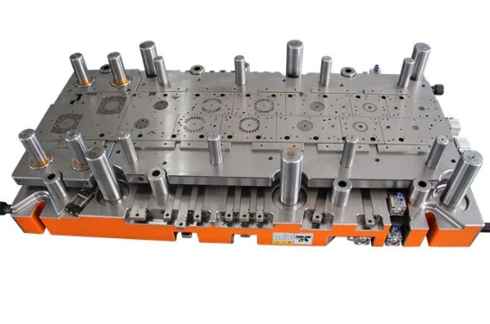
Kapag tumataas ang dami ng produksyon papuntang daan-daang libo o milyon, ang progressive dies ay naging mga pangunahing die sa metal forming ang mga sopistikadong stamping die na ito ay may maraming estasyon na inayos nang pahilis, kung saan ang bawat estasyon ay nagpapagawa ng tiyak na operasyon habang ang metal na strip ay tumatagos sa loob ng tool.
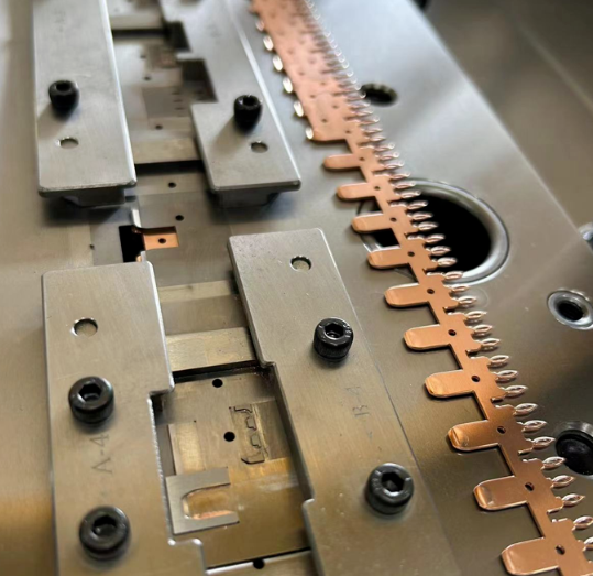
Narito kung paano ito gumagana: isang coil ng sheet metal ang pumapasok sa loob ng die at tumatagos nang tiyak na distansya—tinatawag na pitch—sa bawat presyon ng press. Sa unang estasyon, maaaring butasin ang materyal. Sa ikalawang estasyon, isang forming die ang magbibigay ng hugis sa isang bahagi. Sa ikatlong estasyon, mangyayari ang isa pang pagkukurba. Patuloy ito hanggang sa huling estasyon kung saan hihiwalayin ang natapos na bahagi mula sa carrier strip.
Ang progressive die ay nag-aalok ng malinaw na mga pakinabang para sa angkop na mga aplikasyon:
- Hindi Karaniwang Bilis – Maraming operasyon ang natatapos sa isang presyon lamang ng press, na nagpapahintulot sa produksyon ng daan-daang o libu-libong bahagi kada oras
- Patas na Kalidad – Kapag na-adjust na, ang progressive tooling dies ay gumagawa ng mga eksaktong katulad na bahagi sa bawat presyon ng press
- Bawasan ang Pagkakahawak – Ang mga bahagi ay nananatiling nakakabit sa carrier strip hanggang sa matapos ang proseso, kaya walang kailangang manu-manong paglipat sa pagitan ng mga operasyon
- Mas mababang gastos bawat bahagi Mataas na paunang pamumuhunan sa tooling ay kumalat sa mga malaking dami ng produksyon
Gayunman, ang progresibong kamatayan ay hindi sa pangkalahatan ang perpektong paraan. Ayon sa Worthy Hardware, ang paunang gastos sa tooling para sa progressive die stamping ay maaaring mataas, ngunit nagiging epektibo lamang ito sa gastos sa produksyon ng malaking dami dahil sa mas mababang gastos sa bawat bahagi. Ang mga sistemang ito ay nakikipagpunyagi rin sa mas malalaking bahagi na hindi umaangkop sa mga praktikal na lapad ng strip, at mas hindi sila angkop para sa mga napaka-kumplikadong geometry na nangangailangan ng makabuluhang reorientation ng bahagi.
Pagpipili sa Paglilipat, Pag-iipon, at Pagbubuo ng mga Di
Hindi lahat ng aplikasyon ay tumutugma sa progresibong modelo ng pag-iipon. Ang mas malalaking bahagi, kumplikadong geometry, at mas mababang dami ay kadalasang nangangailangan ng alternatibong mga diskarte. Ang pag-unawa kung kailan ang bawat uri ng die ay nakamamangha ay tumutulong sa iyo na maiugnay ang mga pamumuhunan sa tooling sa aktwal na mga pangangailangan sa produksyon.
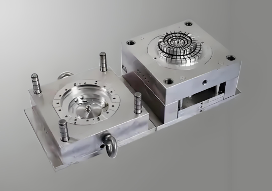
Transfer dies malutas ang limitasyon sa laki na humahadlang sa progresibong mga sistema. Sa halip na panatilihin ang mga bahagi na nakabitin sa isang carrier strip, ang mga transfer dies ay gumagamit ng mga mekanikal o awtomatikong sistema upang pisikal na ilipat ang mga indibidwal na bahagi mula sa istasyon patungo sa istasyon sa loob ng press.
Ang ganitong diskarte ay nagbubukas ng mga posibilidad na hindi matugunan ng progressive dies:
- Ang mas malalaking bahagi na higit sa praktikal na lapad ng banda ay nagiging posible
- Ang mga bahagi ay maaaring i-rotate, i-flipped, o muling ma-orient sa pagitan ng mga istasyon para sa kumplikadong mga pagkakasunud-sunod ng pagbuo
- Maraming mga laki ng walang laman ay maaaring tumakbo sa pamamagitan ng parehong tooling na may minimal na pagbabago
- Ang mga komplikadong hugis na may tatlong sukat na nangangailangan ng pag-access mula sa maraming anggulo ay nagiging posible
Ang pag-aayuno? Ang pag-i-transfer ng stamping ay nagsasangkot ng mas mataas na mga gastos sa pagpapatakbo dahil sa pagiging kumplikado ng pag-set up at pangangailangan ng dalubhasa sa paggawa para sa pagpapanatili at operasyon. Ang oras ng pag-setup para sa bawat pagtakbo ay maaaring maging mas mahaba, lalo na para sa mga komplikadong bahagi, na nakakaapekto sa pangkalahatang mga timeline ng produksyon.
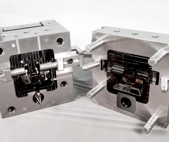
Compound dies mag-adopt ng ganap na iba't ibang paraan. Sa halip na magkakasunod na operasyon sa maraming estasyon, ang compound dies ay nagpapagawa ng maraming operasyon nang sabay-sabay sa isang presyon lamang ng press. Ang isang die na nabuo gamit ang compound tooling ay maaaring blanked, pierced, at shaped nang sabay-sabay.
Ang sabay-sabay na aksyon na ito ay nagbibigay ng mga tiyak na benepisyo:
- Mahusay na dimensional accuracy dahil lahat ng mga katangian ay nililikha sa perpektong alignment
- Epektibong paggamit ng materyales na may kaunting basura
- Mas simple ang konstruksyon ng die kumpara sa progressive systems
- Mas mababang gastos sa tooling para sa angkop na mga aplikasyon
Ang compound dies ay pinakaepektibo para sa mga bahagi na medyo patag at nangangailangan ng mataas na precision ngunit limitado sa kumplikadong disenyo. Mas hindi epektibo ang mga ito para sa mga bahagi na nangangailangan ng malalim na pagguhit (deep draws), maraming pagbend, o mga operasyon na hindi kayang mangyari pisikal na nang sabay-sabay sa iisang stroke.
Forming dies ang mga ito ay kumakatawan sa isang espesyalisadong kategorya sa loob ng metal forming dies—mga tooling na idinisenyo partikular para sa mga operasyon ng pagbuo (shaping) nang walang pag-alis ng materyal. Hindi tulad ng cutting dies na gumagawa ng blanking, piercing, o trimming, ang forming die ay nagbabago ng hugis ng materyal sa pamamagitan lamang ng kontroladong deformation.
Ang mga espesyalisadong die na ito ay nangangasiwa sa mga operasyon tulad ng:
- Pagkukurba at pagpapalawak ng gilid kung saan walang paggupit na nangyayari
- Pagpapahabain at pagpapandak upang lumikha ng mga tampok sa ibabaw
- Mga operasyon sa pagguhit na lumilikha ng lalim nang hindi kinakailangang putulin
- Pagkurol at pagpapalapad ng gilid para sa paggamot sa mga gilid
Ang mga die para sa pagbuo ay kadalasang gumagana kasama ng mga die para sa paggupit sa loob ng mas malalaking sistema ng die, na nangangasiwa sa mga operasyon sa paghubog matapos makuha ang mga blanko sa tamang sukat.
Pagpili ng Uri ng Die sa Isang Sulyap
Ang pagpili sa pagitan ng mga die na ito para sa kagamitan ay nangangailangan ng balanseng pagsasaalang-alang sa maraming kadahilanan nang sabay-sabay. Ang sumusunod na paghahambing ay naglilinaw kung kailan ang bawat paraan ay angkop:
| Uri ng die | Mga Tipikal na Aplikasyon | Kabutihan sa Produksyon na Bolyum | Kakayahan sa Komplikadong Bahagi | Kaugnay na Puhunan sa Kagamitan |
|---|---|---|---|---|
| Progresibong matayog | Maliit hanggang katamtamang laki ng mga bahagi na may maraming katangian; electrical connectors, brackets, clips | Malaking dami (100,000+ na bahagi) | Katamtaman hanggang mataas; limitado ng lapad ng strip at mga pangangailangan sa oryentasyon ng bahagi | Matataas na paunang gastos; pinakamababang gastos bawat bahagi kapag nasa mataas na dami |
| Transfer Die | Mas malalaking bahagi na nangangailangan ng muling oryentasyon; mga panel ng sasakyan, mga komponenteng istruktural, mga kahon ng appliance | Katamtaman hanggang mataas na dami | Napakataas; ang mga bahagi ay maaaring i-rotate at i-reposisyon sa pagitan ng mga estasyon | Mataas; ang karagdagang awtomasyon ay nagdaragdag ng gastos |
| Compound die | Mga patag na bahagi na nangangailangan ng tiyak na pag-align ng maraming katangian; mga washer, gasket, simpleng blankong hugis | Mababa hanggang katamtamang dami | Mababa hanggang katamtaman; limitado sa mga operasyon na maisasagawa sa isang solong stroke | Katamtaman; mas simple ang konstruksyon kaysa sa progressive |
| Forming die | Mga operasyon sa paghubog nang walang pagputol; mga baluktot, draws, embosses, hems | Lahat ng dami depende sa tiyak na disenyo | Nag-iiba-iba nang malawakan batay sa uri ng operasyon sa paghubog | Nag-iiba-iba; madalas ginagamit sa loob ng mas malalaking sistema ng die |
Pansinin kung paano hinahatak ng dami ng produksyon ang karamihan sa desisyong ito. Ang isang bahagi na nangangailangan ng 500 piraso bawat taon ay bihira nangangailangan ng investment sa progressive tooling, samantalang ang isang bahagi na gumagawa ng milyon-milyon bawat taon ay halos tiyak na nangangailangan nito. Ngunit ang dami ay hindi ang tanging salik—ang laki, kumplikadong disenyo, at mga kinakailangan sa toleransya ng bahagi ay lahat nakaaapekto sa pinakamainam na pagpili.
Kapag napili na ang tamang uri ng die, ang susunod na mahalagang yugto ay nagsisimula: ang pagdidisenyo at paggawa ng aktwal na tooling. Ang biyahe mula sa unang konsepto hanggang sa mga die na handa nang gamitin sa produksyon ay kasama ang simulasyon, paggawa, at paulit-ulit na pagpapabuti—na siyang nagdedetermina kung magiging matagumpay o mabibigo ang iyong mga bahagi.
Ang Buong Proseso ng Pag-form ng Die Mula sa Disenyo Hanggang sa Produksyon
Napili mo na ang tamang uri ng die para sa iyong aplikasyon. Ngayon ay dumadating ang tanong na naghihiwalay sa matagumpay na produksyon mula sa mahal na kabiguan: paano nga ba talaga ililipat ang tooling na iyon mula sa konsepto hanggang sa realidad na handa nang gamitin sa produksyon? Ang sagot ay nasa isang sistematikong proseso ng die—na karamihan sa mga tagagawa ay hindi lubos na nauunawaan o binabale-wala ang ilang hakbang dito—at ang mga shortcut na iyan ang mismong dahilan kung bakit nagsisimulang mabigo ang mga bahagi.
Ano ang paggawa ng die sa kanyang pinakasentro? Hindi lamang ito ang pagmamachine ng mga bloke ng metal upang mabuo ang mga hugis. Ang paggawa ng die ay sumasaklaw sa buong inhinyeriyang proseso mula sa pagsusuri sa mga kinakailangan ng bahagi hanggang sa pagpapatunay ng kakayahang mag-produce. Ang bawat yugto ay nakabase sa nauna, at ang mga kahinaan na ipinakilala nang maaga ay dumadagdag sa mga depekto na naging napakamahal na ayusin sa huling yugto.
Sundan natin ang buong workflow na nagbabago ng disenyo ng isang bahagi patungo sa maaasahang tooling na handa na para sa produksyon.
Mula sa Konsepto hanggang sa CAE Simulation
Ang proseso ng pagbuo ng hugis ay nagsisimula nang maaga pa bago pa man i-cut ang anumang bakal. Ayon sa Die-Matic, ang yugto ng disenyo ay kinasasalihan ng mga inhinyero at mga designer ng produkto upang matiyak na ang bahagi ay tumutugon sa ninanais na pagganap, gastos, at mga kinakailangan sa kalidad. Ang kolaboratibong epekto na ito ay tumutugon sa ilang mahahalagang elemento:
- Pagsusuri sa Disenyo ng Bahagi Sinusuri ng mga inhinyero ang geometry ng bahagi para sa pagkabuo, na nagtatampok ng mga katangian na maaaring maging sanhi ng mga problema sa panahon ng produksyon. Ang matingkad na mga sulok, malalim na mga pag-aakyat, at mahigpit na radius ay lahat ng mga hamon na dapat harapin bago magsimula ang disenyo ng tooling.
- Paggawa ng Pagsasanay sa Materyales Ang pagpili ng tamang uri ng sheet metal ay nagsasangkot ng paghahambing sa kakayahang mag-form, lakas, gastos, at mga pangangailangan sa ibaba tulad ng welding o pag-painting. Ang mga katangian ng materyal ay direktang nakakaapekto sa mga parameter ng disenyo ng die kabilang ang mga clearances, radii, at mga pwersa sa pagbuo.
- Ang Tolerance at Specification Definition Ang pagtatatag ng mga kinakailangan sa sukat, mga inaasahan sa pagtatapos ng ibabaw, at mga pamantayan sa kalidad ay lumilikha ng mga patlang kung saan ang lahat ng kasunod na trabaho ay masusukat.
- Mga Input na Nagsasarili Ang mga inhinyero sa paggawa, mga espesyalista sa kalidad, at mga tauhan sa produksyon ay nag-aambag ng mga pananaw na pumipigil sa mga disenyo na hindi maging praktikal upang makagawa sa sukat.
- CAE simulation at validation Ang makabagong mga proseso ng pagbubuo ay lubos na umaasa sa computer-aided engineering upang hulaan ang pag-uugali ng materyal bago umiiral ang pisikal na tooling.
Ang panglimang hakbang na iyon ang simulasiyong CAE ay kumakatawan sa isang pagbabago sa paraan ng pagbuo ng mga matrix sa paggawa. Sa halip na magputol ng mamahaling kasangkapan at umaasa na ito'y magtatrabaho, sinimulo ng mga inhinyero ngayon ang buong proseso ng pagbubuo sa digital. Ayon sa Tebis , ang mga kakayahan sa pag-simula ay nagbibigay-daan sa mga tagagawa na hulaan ang daloy ng materyal, makilala ang mga potensyal na depekto, at i-optimize ang geometry ng die bago ang anumang pisikal na tooling ay gawa.
Ano ang maihula ng simulator? Halos lahat ng maaaring magkamali:
- Mga lugar kung saan ang materyal ay magiging labis na manipis, na may panganib na mag-iyak
- Mga rehiyon na madaling maging may mga wrinkle dahil sa labis na pag-compress
- Pag-uugali ng pag-uumpisa na nakakaapekto sa mga pangwakas na sukat ng bahagi
- Pag-optimize ng laki ng walang laman upang mabawasan ang basura ng materyal
- Pagbuo ng mga kinakailangan ng puwersa upang matiyak na ang kapasidad ng press ay tumutugma sa operasyon
Iniulat ng Tebis na ang kanilang mga proseso ng CAD/CAM ay maaaring maghatid ng mga pagtaas ng kahusayan na lumampas sa 50 porsiyento sa pamamagitan ng pag-automate ng pag-simula at pag-aakyat ng mga problema bago ang pisikal na pagsubok. Sinabi ng isang customer na ang pag-iwas sa kahit isang solong lugar ng presyon ay dati'y nagkakahalaga ng hanggang 10,000 Euros sa mga pagkukumpunimga problema na ngayon ay nakukuha sa digital.
Paggawa ng Die, Pagsusuri, at Pag-unlad ng Production
Kapag nakumpleto na ang pag-simula at napatunayan na ang disenyo ng patong, nagsisimula na ang pisikal na paggawa. Ang yugto na ito ay nagbabago ng mga digital na modelo sa tumpak na tooling sa pamamagitan ng maingat na pagmamanhik at pagsasama.
- Ang Pag-aayos ng Mga Komponente ng Die Ang mga bloke ng Die, punches, at mga bahagi ng suporta ay pinagmulan mula sa mga billet ng tool steel gamit ang CNC milling, grinding, at EDM na mga proseso. Ang modernong software ng CAM ay nagbabalangkas ng mga toolpath na walang pagka-collide at nagpapagana ng awtomatikong programming batay sa nakaimbak na kaalaman sa paggawa.
- Paggamot sa init at Pag-aayos ng ibabaw Ang mga bahagi ng makina ay sumasailalim sa mga proseso ng pag-harding upang makamit ang kinakailangang paglaban sa pagsusuot, kasunod ng huling pag-grinding at pag-polish upang matugunan ang mga pagtutukoy ng pagtatapos ng ibabaw.
- Pandikit na Pangkat Ang mga indibidwal na bahagi ay magkasama sa mga sapatos na may presisyang pag-aayos. Ang mga pin, spring, at stripper ay naka-install at naka-adjust upang matiyak na maayos ang operasyon.
- Unang Pagsusubok Ang naka-assembled na matrikula ay ipinapasok sa isang press para sa unang produksyon ng artikulo. Ipinakikita ng kritikal na yugto na ito kung gaano katumbas ang mga hula ng simulasiyon sa katotohanan. Sinusuri ng mga inhinyero ang kalidad ng bahagi, katumpakan ng sukat, at pagkilos ng pagbuo.
- Pag-aayos ng Pag-uulit-ulit Bihira na makagawa ng perpektong mga bahagi kaagad ang pag-iprograma. Ang mga inhinyero ay nag-aayos ng geometry ng die, nagbabago ng mga clearance, at nagpapahusay ng mga parameter ng pagbuo batay sa mga resulta ng obserbasyon. Ang siklo na ito ay maaaring ulitin nang maraming beses bago makamit ang katanggap-tanggap na kalidad.
- Baliwagan ng produksyon Kapag ang pag-try out ay gumagawa ng pare-pareho, katanggap-tanggap na mga bahagi, ang pinalawak na pagpapatakbo ng produksyon ay nagpapatunay ng kakayahang proseso. Ang kontrol sa proseso ng istatistika ay nagtatatag na ang die ay maaasahan na makagawa ng mga bahagi sa loob ng mga pagtutukoy.
- Pagsisimula ng Produksyon Ang mga validated tooling ay pumapasok sa regular na produksyon, na may mga sistema ng pagsubaybay na nagsubaybay ng mga metrik ng kalidad at kondisyon ng pag-iipon sa paglipas ng panahon.
Ang yugto ng pagsubok ay nararapat ng partikular na pansin sapagkat doon ang simulasiyon ay nakakasama ng katotohanan. Ayon kay Tebis, ang mga kakayahan ng reverse engineering ay nagbibigay-daan sa mga tagagawa na mag-scan ng manu-manong binago na mga dies sa panahon ng pagsubok at i-update ang mga modelo ng CAD batay sa mga pisikal na pagbabago. Ito'y nagsisiguro na ang dokumentasyon ay tumutugma sa aktwal na kagamitan sa produksyon na mahalaga para sa hinaharap na pagpapanatili at pagpapalit.
Ang pagbabayad ng pag-ikot ay naglalarawan kung bakit mahalaga ang ganitong pang-uulit-ulit na diskarte. Habang ang simulasiyon ay naghula sa pag-uugali ng springback, ang aktwal na mga lote ng materyal ay maaaring kumilos nang bahagyang naiiba. Sinabi ni Tebis na ang pagpapatupad ng deformasyon na teknolohiya sa mga ibabaw ng CAD ay nagbibigay-daan sa mas mabilis na mga pag-aayos kaysa sa mga tradisyunal na pamamaraan ng pag-aayos, na binabawasan ang bilang ng mga loop ng pag-aayos na kinakailangan bago makamit ang naaprubahang geometry.
Ang buong proseso ng pag-iiponmula sa paunang ideya hanggang sa pagpapatunay sa produksyonkaraniwan ay tumatagal ng mga linggo hanggang buwan depende sa pagiging kumplikado. Ang pagmamadali sa anumang yugto ay nagdudulot ng mga panganib na dumami sa ibaba. Ang isang shortcut sa pag-simula ay maaaring makatipid ng mga araw sa simula pero nagkakahalaga ng mga linggo sa pinalawig na pagsubok. Ang hindi sapat na pagpapatunay sa pagsubok ay maaaring mag-clear ng tooling para sa produksyon upang lamang matuklasan ang mga isyu sa kakayahan pagkatapos na libu-libong mga may depekto na bahagi ang naipadala.
Ang pag-unawa sa buong daloy ng gawain na ito ay tumutulong sa mga inhinyero na kilalanin kung bakit nangyayari ang mga kabiguan sa pagbuo ng die. Maraming depekto ang nagmumula hindi sa mismong operasyon ng pagbuo, kundi sa mga desisyon na ginawa—or sa mga hakbang na napalampas—sa panahon ng proseso ng pagpapaunlad. Ang mga materyales na pinili para sa paggawa ng die ay may kasing-kritikal na papel din sa pangmatagalang tagumpay, kung saan tayo pupunta sa susunod.
Mga Materyales ng Die at Kanilang Epekto sa Pagganap at Buhay na Tagal
Ginawa mo na ang perpektong geometry ng die at sinubukan ito sa pamamagitan ng simulasyon. Ngunit narito ang isang tanong na nagpapalagay ng mga kahit na eksperyensiyadong inhinyero: ano ang mangyayari kapag ang magandang disenyo ng metal na die ay nagsisimulang mabilis na pumutol, biglang sumisira, o gumagawa ng mga bahagi na may bumababa nang kalidad pagkatapos lamang ng isang maliit na bahagi ng inaasahang buhay nito?
Ang sagot ay halos laging nauuugnay sa pagpili ng materyales. Ang pagpili ng tamang bakal para sa die ay hindi lamang tungkol sa pagpili ng pinakamalakas na opsyon na available—kundi tungkol sa pagtutugma ng mga katangian ng materyales sa mga tiyak na pangangailangan na haharapin ng iyong tooling. Ayon sa MetalTek, dahil bawat aplikasyon ay iba-iba, walang mahika o "isang sukat para sa lahat" na alloy para sa tooling. Ang susi ay nasa pag-unawa kung paano nag-iinteract ang mga katangian ng materyales sa iyong mga kinakailangan sa produksyon.
Pagpili ng Tool Steel para sa Haba ng Buhay ng Die
Kapag pumipili ng materyales para sa paggawa ng tool at die, kailangan ng mga inhinyero na suriin ang ilang magkakaugnay na katangian. Ang pagtuon lamang sa isang katangian—tulad ng hardness—habang binabalewalang ang iba ay humahantong sa maagang pagkabigo na karaniwang nararanasan ng mababang kalidad na tooling.
Narito ang mga kritikal na pamantayan sa pagpili ng materyales na tumutukoy sa pagganap ng die tool:
- Lakas sa Pagkabigat – Naglalarawan ng punto kung saan ang materyal na nasa ilalim ng karga ay hindi na babalik sa orihinal nitong hugis. Binibigyang-diin ng MetalTek na ang permanenteng dehormasyon sa mga kagamitan para sa paggawa ay karaniwang hindi tinatanggap dahil ito ay nagdudulot ng hindi pare-parehong mga bahagi at maagang kapalit.
- Fatigue Strength – Sukat ng pagtutol sa kabiguan sa ilalim ng paulit-ulit na pagkarga. Kailangan bang gumawa ang iyong die ng 5,000 na bahagi o 5 milyong bahagi? Ito ang magdedetermina kung gaano kahalaga ang pagtutol sa pagkapagod sa iyong pagpili.
- Wear Resistance – Ang kakayahan ng materyal na tumagal laban sa degradasyon ng ibabaw sa pamamagitan ng mga mekanismo ng abrasyon, adhesyon, at erosyon. Para sa karamihan ng mga cold-work die, ito ang pangunahing kadahilanan na nagdedetermina sa operasyonal na buhay ng serbisyo.
- Katatagan – Ang kakayahang absorbohin ang enerhiya ng impact nang hindi sumisira. Ang hardness at toughness ay nasa tuloy-tuloy na tensyon—ang pagtaas ng isa ay karaniwang nagpapababa sa kabuuan ng isa pa.
- Katatagan sa Init – Para sa mga aplikasyon na may mainit na paggawa, ang lakas sa temperatura ng kuwarto ay walang saysay. Ang pangunahing sukatan ay ang lakas sa mainit—kung gaano kahusay ang materyal na panatilihin ang mga katangian nito sa mataas na temperatura.
Ang mga tool steel ay nahahati sa ilang kategorya batay sa mga kondisyon ng operasyon. Ayon kay Jeelix, ang mga cold-work tool steel ay may lakas, impact toughness (tibay laban sa pag-impact), at wear resistance (tibay laban sa pagsuot) para sa mga temperatura na hindi lalampas sa 400°F. Ang mga hot-work grade ay panatilihin ang mga katangiang ito sa mas mataas na temperatura, samantalang ang mga high-speed tool steel ay nananatiling epektibo kahit sa 1000°F.
Kasaganaan ng mga karaniwang grado ng die steel na ginagamit sa mga aplikasyon ng machining die:
- A2 – Mabuting balanse ng wear resistance (tibay laban sa pagsuot) at toughness (tibay); air-hardening (pagpapatigas sa hangin) para sa dimensional stability (estabilidad ng sukat)
- D2 – Mataas na nilalaman ng chromium na nagbibigay ng mahusay na wear resistance (tibay laban sa pagsuot); ideal para sa mataas na dami ng cold forming (pagbuo sa malamig)
- H13 – Ang pangunahing hot-work steel; nananatiling malakas sa mataas na temperatura kasama ang mabuting thermal fatigue resistance (tibay laban sa thermal fatigue)
- S7 – Napakahusay na shock resistance (tibay laban sa shock); angkop para sa mga aplikasyon na may mabigat na impact loading (pagkarga dahil sa impact)
Pag-iisip sa Kagaspangan, Mga Panlabas na Pampatong, at Paggamot sa Ibabaw
Ang mga kinakailangan sa kagaspangan ay nakasalalay nang diretso sa dalawang kadahilanan: ang materyal na binubuo at ang inaasahang dami ng produksyon. Ang pagbuo ng mataas na lakas na bakal ay nangangailangan ng mas makapal na ibabaw ng die kaysa sa pagbuo ng aluminum. Ang pagpapatakbo ng milyon-milyong siklo ay nangangailangan ng mas mataas na paglaban sa pagsuot kaysa sa maikling produksyon.
Ngunit narito ang kadalasang napapaliguan ng maraming inhinyero: ang base na materyal ay simpleng simula lamang. Ang modernong pagganap ng die ay nagmumula sa pagtrato sa metal na die bilang isang sistema—na pinagsasama ang substrate, heat treatment, at surface engineering bilang isang buong solusyon.
Mga Pagtrato sa Surface pahabain nang malaki ang buhay ng die kapag angkop na naaayon sa mga mode ng pagkabigo:
Nitriding nagpapadala ng nitrogen sa ibabaw ng bakal, na bumubuo ng napakahirap na iron nitride compounds. Ayon sa Phoenix ang ion nitriding ay nagbibigay ng kahigpitang lumalampas sa 58 HRC na may mahusay na paglaban sa pagsuot at pagkapagod. Ang lalim ng case ay nasa hanay na 0.0006 pulgada hanggang 0.0035 pulgada, depende sa mga kinakailangan ng aplikasyon. Hindi tulad ng chrome plating na sumasaklaw lamang sa ibabaw, ang nitriding ay gumagawa ng isang metallurgical bond na may mas mataas na lakas at tibay—at nananatiling maaaring i-work ng mga tagagawa ng tool at die ang mga ibabaw nito pagkatapos.
PVD Coatings (Physical Vapor Deposition) ay nagde-deposito ng manipis, mataas na performans na mga layer sa mga ibabaw ng die. Kasama sa karaniwang mga coating:
- TiN (Titanium Nitride) – Pangkalahatang layunin na coating na nagpapabuti ng paglaban sa pagsuot at lubricity
- CrN (Chromium Nitride) – Mahusay na paglaban sa kemikal kasama ang kahigpitang at mababang coefficient ng friction na humigit-kumulang sa 0.5
- TiAlN – Napakahusay na performance sa mataas na temperatura
- DLC (Diamond-Like Carbon) – Napakababa na friction para sa mga demanding na sliding application
Sinabi ng Phoenix na ang PVD processing ay ginaganap sa relatibong mababang temperatura—humigit-kumulang sa 420°F para sa deposition—na nagdudulot ng kaunting o walang distorsyon sa bahagi kapag ang substrate ay na-heat-treat na nang wasto.
CVD Coatings (Chemical Vapor Deposition) lumikha ng mas makapal, pambihirang mahusay na mga layer na nakatali ngunit nangangailangan ng mga temperatura ng proseso na madalas na lumampas sa 1500 ° F. Ginagawa nito ang CVD na hindi angkop para sa mga eksaktong patlang kung saan ang kabalintunaan ay hindi maaaring tanggapin.
Ang ugnayan sa pagitan ng pagpili ng materyal at mga pangangailangan sa pagpapanatili ay karapat-dapat sa maingat na pagsasaalang-alang. Binigyang-diin ng Jeelix ang pagkalkula ng Total Cost of Ownership sa halip na magtuon lamang sa paunang gastos sa materyal. Ang premium die steel na nagkakahalaga ng 50% na mas mataas sa una ay maaaring magdala ng 33% mas mababang kabuuang gastos kapag isinasaalang-alang ang pinalawig na buhay, pinaikling mga agwat ng pagpapanatili, at mas kaunting mga pagkagambala sa produksyon.
Ang pagpili ng tamang kumbinasyon ng base na materyal, paggamot sa init, at engineering sa ibabaw ay nagbabago ng mga dies mula sa mga gastusin sa gastos sa pagkonsumo sa mga pangmatagalang pagmamanupaktura ng mga ari-arian. Ngunit kahit na ang pinakamahusay na mga materyales ay hindi maaaring maiwasan ang bawat problema - pag-unawa sa mga depekto na nangyayari sa panahon ng pagbuo ng mga operasyon, at kung paano maiwasan ang mga ito, ay pantay na mahalaga.
Karaniwang mga Depekto sa Pagbubuo ng Die at Paano Ito Maiiwasan
Pinili mo ang tamang mga materyales ng pag-iipon, pinatunayan ang iyong disenyo sa pamamagitan ng pag-simula, at binuo ang tumpak na mga tool. Gayunman, ang mga bahagi ay pa rin lumalabas sa pag-iimprenta na may mga pang-aak, bitak, o sukat na hindi tumutugma sa mga pagtutukoy. Ano ang naging masama?
Ang katotohanan ay, kahit na ang mga mahusay na disenyo ng mga operasyon sa pagbubuo ng sheet metal ay may mga depekto. Ang pagkakaiba sa pagitan ng mga gumagawa na naguguluhan at mga matagumpay ay hindi ang ganap na pag-iwas sa mga problema - ito ay pag-unawa kung bakit eksaktong nangyayari ang mga depekto at alam kung paano ito sistematikong aalisin. Ayon sa pananaliksik na inilathala sa ScienceDirect , ang mga depekto sa pagbuo ng metal ay pangunahing nahahati sa tatlong kategorya: mga depekto na dulot ng stress, mga depekto na dulot ng daloy ng materyal, at mga depekto na may kaugnayan sa microstructure.
Tingnan natin ang mga karaniwang kabiguan sa proseso ng pagbubuo ng sheet metal at ang mga diskarte na pumipigil sa mga ito.
Pag-unawa sa Springback, Pag-ubo, at Pag-iyak
Ang bawat operasyon sa pagbubuo ng sheet metal ay nakikipaglaban laban sa pangunahing pag-uugali ng materyal. Ang pag-unawa sa mga pag-uugali na ito ay nagbabago ng paglutas ng problema mula sa paghula sa inhinyeriya.
Springback ang mga ito ay maaaring ang pinaka-nakakainis na depekto dahil ang bahagi ay mukhang tama sa die pagkatapos ay nagbabago ng hugis sa sandaling ang presyon ay naglalabas. Ayon sa pagsusuri sa industriya , ang pag-iwas ay nangyayari dahil ang mga sheet ng metal ay may posibilidad na makabalik sa kanilang orihinal na posisyon pagkatapos ng deformasyon ng isang tiyak na porsyento. Nangangahulugan ito na isang bahagi ng deformasyon ang nagbabalik sa unang kalagayan, na nakakaapekto sa katumpakan ng sukat.
Ano ang dahilan kung bakit nag-iiba ang mga springback? Maraming kadahilanan ang nakikipag-ugnayan:
- Mga katangian ng materyales Ang mas mataas na lakas ng pag-aani ng mga materyales ay mas bumabalik; ang elastistikong modulus ay nakakaapekto sa pag-uugali ng pagbawi
- Radios ng kurba Mas mahigpit na radius kumpara sa kapal ng materyal bawasan ang springback
- Kurbadong Anggulo Ang mas malalaking anggulo ay karaniwang gumagawa ng mas malaking pag-ikot
- Direksyon ng grano Ang pagliko ng parallel kumpara sa perpendicular sa direksyon ng pag-roll ay nakakaapekto sa mga resulta
Pagkakaroon ng mga sugat (tinatawag ding pag-uukit) ay nangyayari kapag ang mga pag-uukol sa pag-uukit ay lumampas sa paglaban ng materyal sa pag-ukit. Isipin na pinipilit mo ang isang manipis na sheet mula sa magkabilang gilid - sa wakas ay nag-buckle ito sa halip na maging patas ang pag-compress. Sa proseso ng pagbuo ng metal, ang pag-uukit ay karaniwang nangyayari sa mga lugar ng flange sa panahon ng mga operasyon sa pagguhit o sa mga rehiyon na hindi suportado sa panahon ng pagliko.
Kabilang sa mga pangunahing sanhi ang:
- Hindi sapat na presyon ng blank holder na nagpapahintulot sa materyal na mag-buckle sa halip na dumaloy
- Hindi pantay na pamamahagi ng presyon sa ibabaw ng die
- Ang di-pag-aayos ng pag-i-punch ng Die ay lumilikha ng mga asimetrikong pwersa
- Sobrang materyal sa mga compression zone na walang sapat na suporta
Pagputok at pagsira kumakatawan sa kabaligtaran ng problema—ang tensile stresses na lumalampas sa mga limitasyon ng materyal. Kapag ang sheet metal ay umaabot sa labas ng kanyang forming limit, ito ay nabibiyak. Ayon sa Stamping Simulation, ang pag-unawa sa tunay na ugat na sanhi ng splitting o labis na pagpapalapad ay nangangailangan ng pagsusuri sa mga major at minor strains, na maaaring i-plot sa isang Forming Limit Diagram upang matukoy kung saan at bakit nabigo ang rehiyon.
Ang tearing ay karaniwang dulot ng:
- Mga draw radii na sobrang manipis, na nagdudulot ng stress concentrations
- Kulang na lubrication na humahadlang sa daloy ng materyal
- Sobrang blank holder force na humahadlang sa paggalaw ng materyal
- Mga katangian ng materyal na hindi sapat para sa antas ng pag-form ng proseso
Mga Depekto sa Surface sumasaklaw ang mga ito sa mga scratches, galling, texture na katulad ng orange peel, at die marks na sumisira sa hitsura o pagganap. Karaniwang nauugnay ang mga ito sa kalagayan ng tooling, mga kabiguan sa lubrication, o mga isyu sa kalidad ng materyal imbes na sa pangunahing mekanika ng pag-form.
Mga Estratehiya sa Pag-iwas at Optimalisasyon ng Proseso
Ang pag-iwas sa mga depekto sa mga operasyon ng pagbuo ng sheet metal ay nangangailangan ng pagtugon sa mga ugat na sanhi, hindi lamang sa mga sintomas.
Ang sumusunod na talahanayan ay nag-uugnay ng karaniwang mga depekto kasama ang kanilang mga sanhi at na-probekang solusyon:
| Uri ng Defect | Mga Ugat na Sanhi | Mga Estratehiya sa Pag-iwas |
|---|---|---|
| Springback | Paggaling ng elastisidad pagkatapos ng pagbuo; mataas na lakas ng yield ng mga materyales; kulang na plastik na dehormasyon | Gumawa ng sobrang pagbend para kompensahin; gamitin ang mga teknik ng coinage sa sheet metal para sa mga eksaktong pagbend; ilapat ang kalibrasyon pagkatapos ng pagbuo; i-adjust ang hugis ng die batay sa mga prediksyon mula sa simulasyon |
| Pagkakaroon ng mga sugat | Kulang na puwersa ng blank holder; labis na materyal sa compression; mahinang pag-align ng die at punch | Dagdagan ang presyon ng blank holder; magdagdag ng draw beads upang kontrolin ang daloy ng materyal; i-optimize ang sukat ng blank; tiyaking tama ang alignment ng tooling |
| Pagsira/Pagputok | Tensile stress na lumalampas sa mga limitasyon ng materyal; maipit na mga radius; kulang na lubrication; labis na pagpigil | Palawakin ang mga draw radii; mapabuti ang lubrication; bawasan ang puwersa ng blank holder; piliin ang mas madaling ipagawa na grado ng materyal; isaalang-alang ang rubber pad forming para sa mas banayad na distribusyon ng presyon |
| Mga Depekto sa Surface | Nagamit na mga kagamitan; kontaminasyon; hindi sapat na paglilipat ng lubrication; mga isyu sa kalidad ng materyal | Regular na pagpapanatili ng die; tamang pagpili at aplikasyon ng lubricant; pagsusuri sa materyal; paggamit ng surface treatment sa mga bahagi ng die |
| Hindi Tumpak na Dimensyon | Mga kamalian sa kompensasyon ng springback; pagbabago ng temperatura; pagkasira ng die; kawalan ng pagkakapareho sa proseso | Kompensasyon na napatunayan gamit ang CAE; kontrol sa temperatura; nakatakda na pagpapabuti ng die; pagmomonitor ng proseso kasama ang feedback control |
Bukod sa pagtugon sa mga indibidwal na depekto, ang mga tagumpay na tagagawa ay nagpapatupad ng sistematikong pag-iwas sa pamamagitan ng ilang pangunahing gawain:
Optimisahin ang mga variable sa pagbuo nang sistematiko. Sa halip na pabalang na i-adjust ang mga parameter, kalkulahin ang pinakamainam na mga halaga batay sa mga katangian ng materyal. Kasali dito ang mga puwersa sa pagbuo, bilis ng punch, radius ng pagkukurba, at mga clearance. Isaisip ang mga katangian tulad ng tensile strength, formability, ductility, at elongation kapag itinatayo ang mga window ng proseso.
Siguraduhing compatible ang die at worksheet. Ang mga materyales para sa die at punch ay dapat na malinaw na mas matatag at mas rigido kaysa sa worksheet na binubuo. Kapag ang materyal ng die ay hindi kayang sapat na tumutol sa presyon ng pagbuo, ito ay nababago ang anyo at nabigo. Halimbawa, ang pagbuo ng mga sheet ng stainless steel ay karaniwang nangangailangan ng mga die na gawa sa HSS o carbide imbes na sa mas malalambot na tool steels.
Gamitin ang simulasyon para sa paghahProgno ng mga depekto. Ang mga modernong CAE tool ay nakakadetekta ng mga problema bago pa man ito umabot sa shop floor. Ayon sa Stamping Simulation , ang advanced na pag-simula ng pagbuo na ginagamit nang maaga sa yugto ng disenyo ay nangangahulugan na ang mga karaniwang depekto sa sheet metal ay hindi kailanman nakararating sa produksyon. Ang kalinawan at bilis ng pagkuha ng impormasyon tungkol sa strain sa pamamagitan ng simulasyon ay mas mataas kaysa sa pisikal na pagkolekta ng datos, na nagpapabilis sa pagsusuri ng ugat na sanhi nang walang interupsiyon sa produksyon.
I-implement ang real-time na pagsubaybay sa proseso. Kahit ang mga prosesong na-verify ay maaaring mag-drift. Ang mga sensor na sumusubaybay sa puwersa ng pagbuo, pag-feed ng materyal, at mga sukat ng bahagi ay nagbibigay ng feedback na nagpapahintulot sa agarang pagwawasto bago pa man makapag-umpisa ang pag-akumula ng mga depektibong bahagi.
Kalkulahin nang tumpak ang kompensasyon para sa springback. Dahil ang springback ay isa sa mga pinakapansamantala at pangmatagalang depekto sa sukat, ang pagpapanatili ng bahagyang mas mataas na target sa katiyakan sa panahon ng disenyo ng die ay nagkakompensa sa hindi maiiwasang elastic recovery. Ang mga kasangkapan sa pagsisimula ay nagtataya ng pag-uugali ng springback, ngunit ang pagpapatunay gamit ang aktuwal na mga batch ng materyal ay nananatiling mahalaga.
Ang pag-unawa sa mga mekanismo ng depekto ay nagbabago mula sa reaktibong paglutas ng problema patungo sa proaktibong pag-iwas. Ngunit ang mga teknolohiya na nagpapagana ng pagbabagong ito ay patuloy na umuunlad nang mabilis—ang mga servo press, integrasyon ng CNC, at mga smart die system ay nagrere-define kung ano ang posible sa precision forming.
Mga Modernong Teknolohiya sa Die Forming na Nagpapabago sa Industriya
Natuunan mo na pigilan ang mga depekto sa pamamagitan ng tamang pagpili ng materyal, pagsisimula, at kontrol ng proseso. Ngunit narito ang naghihiwalay sa mga tagagawa na patuloy na nahihirapan sa mga isyu ng kalidad mula sa mga tagagawa na nakakamit ng halos zero defect rate: ginagamit nila ang mga teknolohiya na pundamental na nagbabago kung ano ang posible sa precision forming.
Ang tradisyonal na mekanikal at hidraulikong press ay gumagana gamit ang mga nakatakda na stroke profile—ang ram ay gumagalaw sa mga bilis na tinutukoy ng mga mekanikal na kabit o mga rate ng daloy ng hidrauliko. Para sa maraming aplikasyon, ito ay sapat na. Ngunit kapag binubuo mo ang mga kumplikadong heometriya sa mataas na lakas na materyales, ang mga limitasyong ito ang naging hadlang sa pagitan ng mga bahagi na tinatanggap at ng mga itinatapon dahil sa depekto.
Teknolohiya ng Servo Press at Kontrol na May Katiyakan
Isipin ang pagkontrol hindi lamang sa dami ng puwersa na inilalapat ng iyong die press, kundi sa eksaktong paraan kung paano lumalawak ang puwersang iyon sa bawat milimetro ng stroke. Ito ang ibinibigay ng teknolohiya ng servo-driven press—at ito ang nagpapabago sa mga kayang maisakatuparan ng mga tagagawa gamit ang mga mahihirap na materyales.
Ayon sa ATD, ang mga servo press ay nagbibigay ng kakayahang programmable at variable stroke speeds, na nagbibigay sa mga tagagawa ng mas malaking kontrol sa daloy ng materyales, sa mga anggulo ng pagkurbang (bend angles), at sa mga puwersang ginagamit sa pagbuo (forming forces). Ang fleksibilidad na ito ay nagpapahintulot sa tumpak na paglikha ng mga kumplikadong hugis habang pinakakabababa ang mga depekto tulad ng pagkukurba (wrinkling), pagputol (tearing), o pagbabalik (springback).
Ano ang nagpapabukod-tangi sa teknolohiyang servo kumpara sa mga konbensyonal na sistema? Gumagana ang die machine gamit ang mga electric motor na eksaktong kontrolado ang posisyon, bilis, at puwersa ng ram sa bawat punto ng stroke cycle. Hindi tulad ng mga mekanikal na press na nakakabit sa sinusoidal motion profiles, ang mga servo system ay maaaring:
- Pabagalin sa mga mahahalagang punto ng pagbuo – Ang pagbawas ng bilis habang una pang nakikilala ang materyal ay nagpapabawas ng shock loading at nagpapabuti ng kalidad ng ibabaw
- Manatili sa ilalim ng presyon – Ang paghawak ng posisyon sa bottom dead center ay nagbibigay-daan sa materyal na lubos na pumasok sa loob ng mga die cavity
- Baguhin ang aplikasyon ng puwersa – Ang pag-aadjust ng presyon sa buong stroke ay nag-optimizes sa ugali ng materyal
- I-customize ang mga profile para sa bawat operasyon – Ang iba’t ibang bahagi ay maaaring i-run gamit ang ganap na magkakaibang katangian ng stroke
Ang mga kakayahan na ito ay lubos na kapaki-pakinabang lalo na sa pagbuo ng mga aplikasyon sa pagmamanupaktura na kinasasangkutan ng mga materyales na may manipis na sukat, mataas na lakas na bakal, at mga padron ng aluminum. Sinasabi ng ATD na ang mga komponente na may kumplikadong disenyo ay tumutulong sa pag-optimize ng pagganap ng sasakyan habang sumusuporta sa mga layunin sa pagbawas ng timbang—at ang teknolohiyang servo ang nagpapagawa ng mga disenyo na ito.
Ang mga pakinabang sa kahusayan ay umaabot nang higit pa sa kalidad lamang ng pagbuo. Ang mga press na may servo ay nagtiyak ng pare-pareho at muling maulit na resulta para sa mga aplikasyon na nangangailangan ng mahigpit na toleransya. Ang mga proseso tulad ng flanging, coining, at embossing ay nakikinabang sa antas ng kontrol na ito, na nagpapahintulot sa mga tagagawa na mag-produce ng mataas na dami nang may pinakamaliit na pagkakaiba.
Integrasyon ng CNC at Matalinong Sistema ng Die
Ang isang sopistikadong press tool ay halos walang saysay kung ang die mismo ay hindi kayang ipaalam ang nangyayari sa loob ng produksyon. Dito ang matalinong kagamitan ay nagbabago mula sa reaktibong kontrol sa kalidad patungo sa proaktibong pamamahala ng proseso.
Ayon sa Keneng Hardware, ang smart tooling ay nagsisilbing i-embed ng iba't ibang sensor nang direkta sa mga metal stamping dies. Sa panahon ng stamping process, ang mga sensor na ito ay nagmomonitor ng mahahalagang kadahilanan tulad ng temperatura, presyon, puwersa, at lokasyon. Ang real-time na data ay nagbibigay ng impormasyon tungkol sa pagganap ng die at sa mga kondisyon ng pagbuo na dati ay hindi nakikita.
Ano nga ba ang kayang tukuyin ng in-die sensing? Higit pa kaysa sa inaasahan mo:
- Distribusyon ng Lakas – Ang mga sensor ay nakikilala ang di-pantay na paglo-load na nagdudulot ng maagang pagsu-surface o depekto sa bahagi
- Pagbabago sa temperatura – Ang pagtaas ng init ay nakaaapekto sa ugali ng materyal at sa buhay ng die; ang pagmomonitor ay nagpapahintulot ng interbensyon bago pa man dumating ang mga problema
- Katumpakan ng posisyon – Ang pagpapatunay ng tamang pagkakalagay ng materyal at alignment ng punch ay nagpipigil sa pagbuo ng mga bahaging may maling hugis
- Konsistensya mula sa isang cycle hanggang sa susunod – Ang pagsubaybay sa mga trend ng pagbabago ay nagpapakita ng proseso ng pagkalugit bago pa man lumabas ang mga bahaging hindi naaaprubahan
Ang patuloy na feedback loop na ito ay nagpapahintulot sa mga operator at awtomatikong sistema na subaybayan ang pagganap ng die at matukoy ang mga pagkakaiba mula sa ideal na kondisyon. Ang real-time monitoring ay napakahalaga upang maagapan ang mga problema, maiwasan ang mga depekto, at matiyak ang pare-parehong kalidad ng produkto.
Ang data na nabubuo ng smart manufacturing tooling ay higit pa sa simpleng pagmamarka ng mga agarang isyu. Ang mga advanced analytics platform ay binabasa ang impormasyon mula sa mga sensor upang tukuyin ang mga trend sa pagganap sa paglipas ng panahon. Nakakakuha ang mga tagagawa ng mga insight kung paano kumikilos ang kanilang mga die sa loob ng libo-libo o milyon-milyong cycles—na impormasyon na nagsisilbing gabay sa parehong agarang pagwawasto ng proseso at pangmatagalang pagpapabuti ng tooling.
Marahil ang pinakamahalagang kakayahan? Ang prediktibong pagpapanatili. Sa pamamagitan ng patuloy na pagsubaybay sa kalagayan ng die, ang mga tagagawa ay maaaring hulaan kung kailan kailangan ng pagpapanatili imbes na hintayin ang mga pagkabigo. Ang proaktibong paraan na ito ay nababawasan ang hindi inaasahang paghinto ng operasyon, nagpapahaba ng buhay ng tool, at pinipigilan ang mga depekto sa mga bahagi na nangyayari kapag ang mga ginamit nang matagal na die ay nananatili pa rin sa produksyon nang sobrang tagal.
Ang mga operasyon sa pagputol at pagbuo ng machine die ay unti-unting nanghihimig kasama ang mas malawak na mga sistema ng awtomatikong kontrol. Ang mga smart die ay nakikipag-ugnayan sa mga kontrol ng press, kagamitan sa paghawak ng materyales, at mga sistema ng pagsusuri ng kalidad upang lumikha ng mga saradong selula ng pagmamanupaktura. Kapag ang mga sensor ay nakakadetekta ng isang kondisyon na nasa labas ng tinatanggap na saklaw, ang sistema ay maaaring awtomatikong i-adjust ang mga parameter, itala ang mga bahagi para sa pagsusuri, o itigil ang produksyon—lahat ito nang walang interbensyon ng operator.
Ang mga teknolohiyang ito ay hindi panghinaharap na konsepto—ito ay mga realidad sa produksyon na nagbabago ng kompetitibong dinamika sa buong mga industriya. Ang pag-unawa kung paano ginagamit ng iba't ibang sektor ang mga kakayahan na ito ang nagpapaliwanag kung bakit ang ilang tagagawa ay nakakapaghatid nang paulit-ulit ng mga resulta na mahirap tularan ng iba.
Mga Aplikasyon sa Industriya Kung Saan Nagdudulot ng Resulta ang Die Forming
Naunang inaral mo na ang mga teknolohiya na nagbabago sa precision forming—ang mga servo press, smart dies, at integrated automation. Ngunit narito ang nag-uugnay sa lahat ng mga kakayahan na ito: ang mga industriya na humihingi ng mga ito. Bawat sektor ay may natatanging hamon, at ang pag-unawa sa mga pagkakaiba na ito ang nagpapakita kung bakit ang mga solusyon sa tooling na gumagana nang mahusay sa isang aplikasyon ay lubos na nabigo sa isa pa.
Isipin ito sa ganitong paraan: ang isang stamping die na gumagawa ng mga automotive bracket ay nakakaharap sa lubos na iba't ibang kailangan kaysa sa isa pang gumagawa ng aerospace structural components. Ang mga toleransya, mga materyales, dami ng produksyon, at mga kinakailangan sa kalidad ay lubos na nagkakaiba. Ang pagtutugma ng mga die at mga kakayahan sa stamping sa mga kailangang ito ang nagpapasya kung ang mga tagagawa ay magiging matagumpay o magkakaroon ng paulit-ulit na rework.
Mga Aplikasyon sa Pagbuo ng Die para sa Automotive at Aerospace
Ang industriya ng automotive ang pinakamalaking kumokonsumo ng metal stamping dies sa buong mundo, at may mabuting dahilan para dito. Ang bawat sasakyan ay naglalaman ng libu-libong nabuo na mga bahagi mula sa metal, mula sa mga nakikitang body panels hanggang sa mga nakatagong structural reinforcements. Ayon sa Neway Precision, ang stamping at deep drawing ay mahalaga sa paggawa ng malalaki at matitibay na bahagi ng sasakyan na may mataas na kahusayan—mga bahaging kailangang sumunod sa mahigpit na mga pamantayan sa kalidad.
Ang mga aplikasyon sa automotive ay sakop ng napakalawak na hanay:
- Mga panel ng katawan – Mga pinto, takip ng motor, fender, at mga panel ng bubong na nangangailangan ng mahusay na surface finish para sa pagpipinta at Class A appearance
- Mga Komponente ng Estraktura – Mga floor pan, pillar, at mga reinforcement kung saan ang strength-to-weight ratio ang nagpapadetermina sa crash performance
- Mga bracket at mount – Mga bracket ng engine, mga bahagi ng suspension, at mga reinforcement ng chassis na nangangailangan ng mabibigat na toleransya para sa assembly
- Mga bahagi ng sistemang pang-sulat – Mga tangke at housing na ginagawa sa pamamagitan ng deep drawing para sa seamless at leak-proof na konstruksyon
Ano ang nagpapagawang partikular na mahirap ang automotive die manufacturing? Ang kombinasyon ng mataas na dami ng produksyon, mahigpit na toleransya, at hindi mapagpatawad na mga kinakailangan sa kalidad. Ang Neway ay nag-uulat ng mga toleransya na hanggang sa ±0.01 mm para sa mga stamping operation, kasama ang mga rate ng produksyon na umaabot sa 150 na bahagi kada oras para sa mga kumplikadong chassis component. Ang ganitong kahusayan ay napakahalaga dahil kahit ang pinakamaliit na pagkakaiba ay maaaring magdulot ng mga problema sa assembly o kakulangan sa performance.
Para sa mga tagagawa na naglilingkod sa mga automotive OEM, ang sertipikasyon ay labis na mahalaga. Ang mga supplier na sertipikado sa IATF 16949 tulad ng Shaoyi magbigay ng mga solusyon sa pagpapadruk ng stamping die na may kahusayan, na nakauugnay sa mga tiyak na pamantayan na ito, na may kakayahang sakop mula sa mabilis na paggawa ng prototype hanggang sa mataas na dami ng produksyon. Ang kanilang 93% na rate ng unang pag-apruba ay nagpapakita kung paano ang advanced na CAE simulation ay nakakaiwas sa mahal na paulit-ulit na pagpapaunlad na karaniwang kinakaharap ng mga supplier na may mas limitadong kakayahan.
Aerospace Application kailangan ng mas mahigpit na kahusayan ngunit karaniwang sa mas mababang dami. Ayon sa Alicona, ang mga bahagi para sa aerospace ay nangangailangan ng toleransya na umaabot sa ±2–5 microns—na malayo sa karaniwang mga pamantayan para sa automotive.
Ang mga die para sa aerospace para sa mga aplikasyon sa press ay kasali ang:
- Mga istruktural na bracket at fitting – Mga bahagi na gawa sa aluminum at titanium kung saan ang pagbawas ng timbang ay direktang nakaaapekto sa kahusayan ng paggamit ng fuel
- Mga sistema ng fastener – Mga die para sa thread rolling na gumagawa ng mga bolt na may kalidad para sa aerospace gamit ang exceptional na lakas sa pamamagitan ng cold-forming imbes na sa pamamagitan ng pagputol
- Mga seksyon ng panel – Mga balat na gawa sa aluminum na nabuo para sa fuselage at mga istruktura ng pakpak
- Komponente ng Motor – Mga bahagi na gawa sa high-temperature alloy na nangangailangan ng espesyal na pamamaraan sa pagbuo
Ang mga pagsasaalang-alang sa materyales ang naghihiwalay sa aerospace mula sa automotive. Habang ang automotive ay gumagamit nang mas dumarami ng mataas na lakas na bakal at aluminum, ang aerospace ay umaasa nang malaki sa mga alloy ng titanium, nickel superalloys, at espesyalisadong mga grado ng aluminum. Ang mga materyales na ito ay nagdudulot ng mga hamon sa pagbuo na nangangailangan ng mga exceptional na materyales para sa die, tiyak na kontrol sa proseso, at madalas na mga teknik sa pagbuo sa mataas na temperatura.
Paggawa ng Mga Pananim na Pangkonsumo at Kagamitan sa Industriya
Bukod sa automotive at aerospace, ang mga aplikasyon ng sheet metal die ay kumakalat sa halos bawat sektor ng paggawa. Ang mga kinakailangan ay iba-iba—ngunit ang pangunahing mga prinsipyo ng pagtutugma ng kakayahan ng tooling sa mga pangangailangan ng aplikasyon ay nananatiling pareho.
Paggawa ng Appliance ay isang pangunahing tagagamit ng mga nabuo na komponente ng metal:
- Mga panel ng refriyerator at oven – Mga bahagi ng malaking format na nangangailangan ng pare-parehong surface finish at tiyak na sukat para sa pag-aassemble
- Mga drum ng washing machine at dryer – Mga cylindrical na bahaging malalim na hinubog na nangangailangan ng pantay na distribusyon ng kapal
- Mga housing ng control panel – Mga kahon na nabuo nang may kahusayan para sa mga komponenteng elektroniko na may mahigpit na mga kinakailangan sa pag-mount
- Mga pangunahing istruktura – Mga elemento na nagpapadala ng beban kung saan ang rigidity at pagkakapantay ng sukat ang nagtatakda sa katatagan ng appliance
Ang produksyon ng appliance ay karaniwang isinasagawa sa mataas na dami kasama ang katamtamang mga kinakailangan sa toleransya. Ang pokus ay lumilipat patungo sa hitsura ng ibabaw at pare-parehong pagkakasya sa pag-aassemble, imbes na sa kahusayan na nasa antas ng micron na kinakailangan sa aerospace.
Pagmamanupaktura ng electronics at konektor ay nasa kabaligtaran nitong dulo—napakahirap na mga toleransya sa mga maliit na komponente. Ayon sa Alicona, ang mga housing ng electronic connector ay nangangailangan ng kahusayan sa antas ng mikrometro dahil ang mga komponente ay kailangang eksaktong kasya sa loob ng mga sistema ng housing. Ang mga metal stamping die para sa mga aplikasyong ito ay gumagawa ng libu-libong kumplikadong bahagi bawat oras gamit ang mga progressive die system na in-optimize para sa bilis at pagkakasunod-sunod.
Mga Aplikasyon sa Industriyal na Kagamitan isama:
- Mga kahon at kabinet – Mga nabuong bakal na housing para sa mga sistemang elektrikal at mekanikal
- Mga bahagi ng HVAC – Mga ductwork, housing, at mga elemento ng istruktura
- Mga bahagi ng kagamitang pang-agrikultura Mga bahagi ng mabibigat na gauge na nangangailangan ng katatagan sa mahihirap na kapaligiran
- Mga panel ng kagamitan sa konstruksiyon Mga bahagi ng malaking format na pinagsasama ang mga kinakailangan sa istraktura at mga pag-iisip sa estetika
Paano magkakaiba ang mga kinakailangan sa mga sektor na ito? Ang sumusunod na paghahambing ay naglalarawan ng mga pangunahing pagkakaiba:
| Industriya | Tipikal na Mga Toleransiya | Mga dami ng produksyon | Pangunahing Materyales | Mga Pangunahing Tagapag-udyok ng Kalidad |
|---|---|---|---|---|
| Automotive | ±0.01 hanggang ±0.1 mm | Napakataas (milyon/taon) | High-strength steel, aluminum | Katumpakan ng sukat, pagtatapos ng ibabaw, pagganap ng pag-crash |
| Aerospace | ang mga ito ay dapat na may mga pag-andar ng pag-andar ng pag-andar ng pag-andar ng pag-andar ng pag-andar ng pag-andar ng pag-andar ng pag-andar ng pag-andar ng pag-andar ng pag-andar ng pag-andar ng pag-andar ng pag-andar ng pag-andar ng pag-andar ng pag- | Mababa hanggang Medyo | Titanium, aluminum alloys, superalloys | Mataas na katumpakan, integridad ng materyal, kakayahang mag-trace |
| Mga Kagamitan | ±0.1 hanggang ±0.5 mm | Mataas | Ang mga de-koryenteng metal ay may mga de-koryenteng metal na may mga de-koryenteng metal | Paglalarawan ng ibabaw, pagiging angkop ng pagpupulong, kahusayan ng gastos |
| Electronics | ang mga ito ay dapat na may mga pag-andar ng pag-andar ng pag-andar ng pag-andar ng pag-andar ng pag-andar ng pag-andar ng pag-andar ng pag-andar ng pag-andar ng pag-andar ng pag-andar ng pag-andar ng pag-andar ng pag-andar ng pag-andar ng pag-andar ng pag- | Napakataas | Mga alyu ng tanso, mga espesyal na metal | Ang kabuuang katumpakan, mga katangian ng kuryente, pagkakapareho |
| Kagamitan sa Industriya | ang mga ito ay dapat na may isang mas mataas na temperatura ng pag-andar | Mababa hanggang Medyo | Carbon Steel, Stainless Steel | Ang integridad ng istraktura, katatagan, gastos |
Pansinin kung paano nakaaapekto ang mga pangangailangan sa dami sa mga pasiya sa paggawa. Ang mga application sa automotive at electronics na may mataas na dami ay nagpapahayag ng malaking pamumuhunan sa mga tooling dahil ang mga gastos ay nakalat sa milyon-milyong bahagi. Ang mas mababang dami ng mga aplikasyon sa aerospace at industriya ay nangangailangan ng iba't ibang mga kalkulasyon sa ekonomiya na kadalasang nag-aambag ng kakayahang umangkop sa pinakamataas na bilis ng produksyon.
Ang pagpili ng materyal ay gayundin na nag-iiba ayon sa sektor. Ang paglipat ng industriya ng kotse patungo sa mataas na lakas na mga bakal at aluminyo para sa magaan na timbang ay lumilikha ng mga hamon na nangangailangan ng advanced na pag-simula at kontrol sa proseso. Ang mga eksotiko na alyuho ng aerospace ay nangangailangan ng mga espesyal na materyal at kadalasan ay mga pamamaraan ng pagbubuo sa mainit. Ang pagbibigay-diin ng paggawa ng kagamitan sa kahusayan ng gastos ay nag-uuna sa mahabang buhay at minimal na pagpapanatili kaysa sa pag-iipon ng mga limitasyon ng materyal.
Ang pag-unawa sa mga kundisyong ito na partikular sa industriya ay tumutulong sa mga inhinyero na pumili ng angkop na mga uri ng mga matrikula, mga materyales, at mga parameter ng proseso. Ngunit anuman ang industriya, isang tanong ang nakadepende sa pagiging epektibo ng proyekto: may kahalagahan ba ang pamumuhunan? Ang pag-aaralan ng mga gastos sa pagbuo ng die at ROI ay nangangailangan ng maingat na pagsusuri ng mga kadahilanan na ating pag-aralan sa susunod.
Mga Pag-iisip sa Gastos at ROI sa Mga Investor sa Die Forming
Nakita mo na kung paano ang mga kinakailangan ng industriya ay bumubuo ng mga desisyon sa tooling ngunit narito ang tanong na sa huli ay tumutukoy kung ang anumang proyekto ng pagbuo ng die ay gumagalaw pa: gumagana ba ang matematika? Ang pag-unawa kung ano ang tunay na ibig sabihin ng tool & die investment ay nangangailangan ng pagtingin sa kabila ng paunang presyo ng pagbili upang makuha ang kumpletong pang-ekonomiyang larawan.
Isipin ang pamumuhunan sa mga kasangkapan na gaya ng pagbili ng sasakyan. Ang presyo ng sticker ay mahalaga, ngunit ang gastos sa gasolina, pagpapanatili, seguro, at ang pangwakas na halaga ng pagbebenta ay tumutukoy sa kung ano ang talagang ginugugol mo sa paglipas ng panahon. Ang pagbuo ng ekonomiya ay gumagana sa parehong paraanat ang mga tagagawa na nakatuon lamang sa mga unang gastos ay madalas na natuklasan na gumawa sila ng mga mahal na pagkakamali.
Ang Pag-invest sa Tooling at Pag-aaral ng Gastos sa Bawat Bahagi
Ano ang mga drive ng mga gastos sa tooling ng die? Ayon sa TOPS Precision, maraming konektado sa isa't isa na kadahilanan ang tumutukoy sa antas ng iyong pamumuhunan:
- Kumplikadong Anyo ng Bahagi Ang mga komplikadong geometry na nangangailangan ng maraming istasyon ng pagbubuo, mahigpit na mga pagpapahintulot, o kumplikadong mga pattern ng daloy ng materyal ay nangangailangan ng mas sopistikadong tooling. Ang simpleng mga bracket ay mas mura kaysa sa malalim na mga bahagi na may maraming tampok.
- Pagpipili ng uri ng Die Ang progresibong mga matrikula para sa mataas na dami ng produksyon ay nangangailangan ng mas malaking paunang pamumuhunan kaysa sa mas simpleng compound o single-operation tooling. Ang gumagawa ng mga matris ay dapat na magbalanse ng kakayahan laban sa gastos.
- Mga Rehimen ng Materyales Ang mga grado ng asero ng tool ay makabuluhang nakakaapekto sa presyo. Ang mga premium na asero tulad ng mga grado ng CPM ay mas mahal kaysa sa pamantayang H13, ngunit maaaring maghatid ng mas mababang kabuuang gastos sa pamamagitan ng pinalawig na buhay.
- Inaasahang dami ng produksyon Ang mga dies na dinisenyo para sa 50,000 shot ay nangangailangan ng ibang konstruksyon kaysa sa mga inaasahan na tumakbo ng 2 milyong siklo. Ang pagbuo ng labis na kakayahan ay nagsasayang ng pera; ang pagbuo ng hindi sapat na kakayahan ay nagkakahalaga ng higit pa sa pamamagitan ng maaga na kapalit.
- Mga tratamentong ibabaw at mga coating Ang pag-nitride, pag-coat ng PVD, at iba pang paggamot ay nagdaragdag ng unang gastos ngunit nagpapalawak ng buhay ng operasyon at binabawasan ang kadalasan ng pagpapanatili.
Narito kung saan ang tool die economics ay nagiging kawili-wili: ang mas mataas na pamumuhunan sa tooling ay madalas na nagbibigay ng mas mababang gastos sa bawat bahagi. Ayon kay Die-Matic, ang pamumuhunan sa de-kalidad na disenyo ng kasangkapan ay tinitiyak ang tumpak at pare-pareho na produksyon, binabawasan ang mga pagkakamali at ang pangangailangan ng muling pagtatrabaho. Ang mas matibay na mga kasangkapan ay nangangailangan ng mas kaunting pagpapanatili at binabawasan ang mga gastos sa pagpapalit sa paglipas ng panahon.
Ang ugnayan sa pagitan ng dami at gastos sa bawat bahagi ay sumusunod sa isang mahulaan na pattern:
| Dami ng Produksyon | Pag-aari ng Pag-invest sa Tooling | Epekto sa Gastos Bawat Bahagi |
|---|---|---|
| Mababang (mas mababa sa 10,000 bahagi) | Mas simpleng tooling; posibleng soft tooling para sa mga prototype | Mas mataas na gastos sa bawat bahagi; ang pag-aamote ng tooling ang nangingibabaw |
| Katamtaman (10,000100,000 na bahagi) | Mga tooling na uri ng produksyon na may katamtamang pag-asa ng buhay | Balanse na ekonomiya; ang mga gastos sa pag-aayos ng mga kagamitan ay may katwiran na pagkalat |
| Mataas (100,000+ na bahagi) | Ang mga de-kalidad na materyales, panlalaki, at konstruksyon para sa pinakamalalaking buhay | Pinakamababang gastos sa bawat bahagi; ang pamumuhunan ay kumalat sa buong malaking dami |
Ano ang nakatagong driver ng gastos sa paggawa ng mga patong? Pag-aalaga. Ayon sa Sheet Metal Industries , Ang kabuuang gastos sa pagmamay-ari ay kinabibilangan ng mga gastos sa kapital, mga gastos sa pagpapatakbo, at mga gastos sa oras ng pag-off minus ang natitirang halaga. Ang mga makinaat mga moldena walang naka-imbak na pagsubaybay sa pagpapanatili ay mas mahirap pamahalaan, na humahantong sa di inaasahang mga kabiguan at mga pag-aalis sa produksyon.
Ang mga gastos sa pagpapanatili ay nagkukumpul sa pamamagitan ng:
- Ang naka-iskedyul na pag-aayos ng mga ibabaw ng pagsusuot
- Pagbabago ng mga suot na mga insert at bahagi
- Hindi-pinlano na mga pagkukumpuni mula sa di-inaasahang mga pagkagambala
- Mga pagkawala ng produksyon sa panahon ng pag-iwas sa pagpapanatili
Ipinaliwanag ng TOPS Precision na ang regular na pagpapanatili ay mas epektibo sa gastos kaysa sa mga emergency repair o buong pagpapalit ng kasangkapan. Ang pagbuo ng mga modular na disenyo na may mga maibabalik na insert sa mga lugar na may mataas na pagsusuot ay binabawasan ang pangmatagalang pasanin sa pagpapanatili ng kalidad ng bahagi sa buong buhay ng tool die making cycles.
Pag-aaralan ang ROI para sa mga proyekto sa pagbuo ng Die
Ang pagkalkula ng pagbabalik ng pamumuhunan ay nangangailangan ng paghahambing ng kabuuang mga gastos laban sa mga alternatibo, hindi lamang ang mga paunang presyo laban sa isa't isa. Ang balangkas ng pagsusuri ay dapat magsama ng:
- Tuklasin ang mga kinakailangan sa produksyon Ang taunang dami, tagal ng programa, mga pagtutukoy ng pagpapahintulot, at mga pamantayan sa kalidad ang nagtatatag ng baseline para sa paghahambing.
- Bilangin ang kabuuang pamumuhunan sa tooling Kasama ang disenyo, paggawa, pagsubok, at paunang pagpapatunay sa produksyon. Huwag kalimutan ang mga oras ng inhinyeriya para sa pag-simula at pag-optimize.
- Tinatayang gastos sa pagpapatakbo Ang mga gastos sa materyal bawat bahagi, mga pangangailangan sa paggawa, pagkonsumo ng enerhiya, at paggamit ng lubricant ay nagkukumpul sa buong buhay ng produksyon.
- Mga gastos sa pagpapanatili ng proyekto Batay sa inaasahang buhay ng patay at mga interval ng pag-aayos, kalkulahin ang naka-iskedyul at mga badyet sa pagpapanatili para sa hindi inaasahan.
- Mga kadahilanan sa mga gastos sa kalidad Ang mga rate ng scrap, mga kinakailangan sa muling pag-aayos, at mga potensyal na pag-angkin sa warranty mula sa mga depektong bahagi ay may makabuluhang epekto sa kabuuang ekonomiya.
- Isaalang-alang ang mga gastos sa pagkakataon Ang downtime para sa pagpapanatili o di-inaasahang mga pag-aayos ay nangangahulugan ng pagkawala ng kapasidad sa produksyon at potensyal na hindi natupad na mga pangako sa customer.
Ang mga koponan ng inhinyero na may mga advanced na kakayahan sa simulasyong CAE ay lubhang nagpapabuti sa mga ekonomyang ito. Shaoyi's ang 93% na diskarte ng unang pag-apruba ay nagpapababa ng mga mahal na pag-iikot na nagpapalawak ng mga badyet sa pag-unlad at nag-iiba sa mga pagsisimula ng produksyon. Ang kanilang mabilis na kakayahan sa pag-prototypepagbibigay ng mga bahagi ng pagpapatunay sa mas kaunti sa 5 arawnagbibigay-daan sa pagpapatunay sa disenyo bago gumawa ng buong pamumuhunan sa produksyon ng tooling.
Binubuo ng Die-Matic ang mga proyekto na ito sa pamamagitan ng paglalaan ng mga prototype sa mga proyekto. Ang unang pamumuhunan sa pagpapatunay ay patuloy na nagbibigay ng mas mataas na ROI kumpara sa pagmamadali sa mga kasangkapan sa produksyon na nangangailangan ng pagbabago.
Ang wakas? Ang mga makinaryang may-kalidad ay kumakatawan sa pamumuhunan, hindi lamang gastos. Ang mga tagagawa na nag-aaralan ng kabuuang gastos sa pagmamay-ari sa halip na ang presyo ng pagbili lamang ay patuloy na nakakamit ng mas mahusay na mga resultamababang gastos sa bawat bahagi, mas kaunting mga depekto, at tooling na nagbibigay ng maaasahang pagganap sa buong inilaan na buhay ng produksyon nito.
Madalas Itinanong na Mga Tanong Tungkol sa Pagbubuo ng Die
1. ang mga tao Ano ang proseso ng pagbuo ng mga matrikula?
Ang pag-uumol ng Die ay isang espesyal na proseso ng paghulma ng metal kung saan ang sheet metal ay pinindot sa pagitan ng mga katumbas na sangkap ng tooling - isang punch at die block - upang lumikha ng mga tumpak na geometry sa pamamagitan ng kinokontrol na deformasyon. Ang proseso ay gumagamit ng tensyon, compression, o pareho upang hugis ang materyal nang hindi ito aalisin, umaasa sa mga mekanikal na katangian ng metal upang makamit ang mga pangwakas na sukat. Hindi katulad ng mga operasyon sa pagputol, ang pagbubuo ng mga matrikula ay nagbabago ng materyal sa pamamagitan ng pag-ukol, pag-flang, pag-embed, at mga pamamaraan sa pagguhit.
2. Ano ang iba't ibang uri ng pagbuo ng mga patay?
Kabilang sa mga pangunahing uri ang progresibong mga patay para sa mataas na dami ng produksyon na may maraming sunud-sunod na istasyon, mga patay na paglipat para sa mas malaking bahagi na nangangailangan ng paggalaw sa pagitan ng mga operasyon, mga patay na compound para sa sabay-sabay na pagputol at pagbuo sa isang stroke, at pagbuo Ang bawat uri ay angkop sa iba't ibang dami ng produksyon, laki ng bahagi, at mga kinakailangan sa pagiging kumplikado. Ang mga progresibong namatay ay nakamamangha sa 100,000+ na mga run ng bahagi, habang ang mga compound na namatay ay mas mahusay na gumagana para sa mas mababang dami na may mga pangangailangan sa katumpakan.
3. Ano ang kahulugan ng paggawa ng die?
Ang paggawa ng Die ay sumasaklaw sa buong paglalakbay sa inhinyeriya mula sa pag-aaral ng mga kinakailangan ng bahagi hanggang sa pagpapatunay ng kakayahang produksyon. Kasama dito ang pagtatasa ng disenyo ng bahagi, pagpili ng materyal, simulasiyon ng CAE para sa paghula ng daloy ng materyal, pag-make ng mga bahagi ng die mula sa tool steel, paggamot sa init, pagpupulong, pagsubok, at pag-refinement ng iterative. Ang modernong paggawa ng die ay gumagamit ng computer-aided engineering upang mahuli ang mga depekto nang digital bago ang pisikal na tooling ay putulin, na makabuluhang binabawasan ang mga gastos sa pag-unlad at mga timeline.
4. Paano mo maiiwasan ang karaniwang mga depekto sa pagbuo ng mga patong tulad ng mga pag-iikot at mga pangit?
Ang pag-iwas sa pag-iwas sa pag-iwas ay nagsasangkot ng overbending upang maibawas, gamit ang mga pamamaraan ng pag-coining para sa katumpakan, at pag-apply ng post-forming calibration batay sa mga hula ng simulasiyon ng CAE. Ang pag-iwas sa pag-aalsa ay nangangailangan ng pagtaas ng presyon ng blank holder, pagdaragdag ng mga pulbos ng draw para sa kontrol ng daloy ng materyal, at pagtiyak ng wastong pag-aalinline ng tooling. Ang pag-iwas sa pag-aalis ay nakatuon sa pagpapalawak ng mga radius ng pag-aalis, pagpapabuti ng lubrication, at pagpili ng mas madaling-mag-form na mga grado ng materyal. Ang mga modernong kasangkapan sa pag-simula ay naghula ng mga suliranin na ito bago magsimula ang produksyon.
5. Anong mga kadahilanan ang nakakaapekto sa pamumuhunan sa tooling ng pagbuo ng tooling at ROI?
Kabilang sa mga pangunahing kadahilanan sa gastos ang pagiging kumplikado ng bahagi, pagpili ng uri ng patong, mga grado ng asero ng tool, inaasahang dami ng produksyon, at mga paggamot sa ibabaw. Ang mas mataas na pamumuhunan sa tooling ay karaniwang nagbibigay ng mas mababang mga gastos sa bawat bahagi sa dami. Ang total cost of ownership analysis ay dapat magsama ng mga gastos sa disenyo, paggawa, pagsubok, pagpapanatili, at kalidad. Ang mga koponan ng inhinyero na may advanced na simulasiyon ng CAE gaya ng 93% na unang-pasa na diskarte ng pag-apruba ni Shaoyi ay binabawasan ang mga mamahaling pag-iiterasyon at nag-aalok ng mas mahusay na ROI sa pamamagitan ng mabilis na prototyping at walang depekto na produksyon