 Pequenas quantidades, altos padrões. Nosso serviço de prototipagem rápida torna a validação mais rápida e fácil —

Segredos dos Serviços de Corte de Chapa Metálica: Combine a Tecnologia ao Seu Projeto
Quais Serviços de Corte em Chapa Metálica Realmente Oferecem
Já se perguntou como uma chapa metálica plana se transforma no suporte preciso na suspensão do seu carro ou na carcaça elegante que protege equipamentos médicos sensíveis? Essa transformação começa com um serviço de corte em chapa metálica — o passo crítico inicial para transformar matérias-primas em componentes funcionais e projetados com precisão.
Em sua essência, este processo envolve a remoção de material de chapas metálicas utilizando métodos de corte especializados que aplicam força, calor ou jatos abrasivos para atingir especificações exatas. Seja você trabalhando com chapas de aço, metais alumínio ou ligas especiais, a técnica de corte escolhida impacta diretamente a qualidade, o cronograma e o orçamento do seu projeto.
Da Matéria-Prima a Peças de Precisão
Pense na fabricação de chapas metálicas como uma jornada. Ela começa com material plano—tipicamente materiais com espessura de 6 mm ou menos—e termina com componentes prontos para montagem em tudo, desde fuselagens de aeronaves até sistemas de telhados metálicos ondulados. A fase de corte é onde o seu projeto literalmente toma forma.
As capacidades modernas de fabricação de metais vão muito além de cortes retos simples. As tecnologias atuais conseguem produzir padrões intricados, tolerâncias rigorosas e geometrias complexas que seriam impossíveis há apenas algumas décadas. De acordo com relatórios do setor, o segmento de fabricação de metais nos Estados Unidos emprega mais de 400.000 trabalhadores qualificados e gera mais de 21 bilhões de dólares anualmente—um testemunho do quão essenciais esses serviços se tornaram.
O Alicate da Fabricação Moderna de Metais
Por que entender as tecnologias de corte é importante antes de contatar oficinas de fabricação perto de mim? Porque o método escolhido influencia todas as decisões subsequentes: tolerâncias das peças, qualidade das bordas, necessidades de processamento secundário e, em última instância, o custo total do seu projeto.
Veja o que torna esse conhecimento tão valioso: cada tecnologia de corte se destaca em cenários específicos. Escolher incorretamente pode significar remoção excessiva de rebarbas, zonas afetadas pelo calor que enfraquecem o material ou simplesmente pagar mais do que necessário por recursos dos quais você não precisa.
Indústrias em todo o espectro da manufatura dependem de serviços profissionais de corte para manter eficiência e precisão:
- Automotivo e transporte: Componentes de chassis, painéis da carroceria e reforços estruturais
- Aeroespacial: Estruturas de aeronaves, componentes de motores e suportes de precisão que exigem tolerâncias rigorosas
- Equipamentos médicos: Instrumentos cirúrgicos, invólucros de dispositivos diagnósticos e estruturas de camas hospitalares
- Construção: Suportes estruturais, dutos de climatização (HVAC) e elementos arquitetônicos
- Energia: Suportes para painéis solares, carcaças para turbinas eólicas e equipamentos de geração de energia
- Eletrónica: Caixas de proteção, dissipadores de calor e suportes de fixação
- Agricultura: Componentes de máquinas, sistemas de armazenamento e equipamentos de irrigação
Para engenheiros, especialistas em compras e gerentes de projetos que avaliam suas opções, as seções a seguir detalham exatamente o que você precisa saber — desde a comparação entre tecnologias a laser, jato d’água e plasma até a compreensão de como a seleção do material afeta sua escolha do método de corte. Você obterá as informações práticas necessárias para associar a tecnologia adequada às exigências específicas do seu projeto.
Cinco Tecnologias de Corte e Quando Usar Cada Uma
Selecionar o método de corte inadequado pode custar milhares em material desperdiçado, retrabalho e prazos perdidos. Imagine escolher plasma quando seus painéis de alumínio finos exigem corte a laser de precisão — ou especificar jato d’água quando uma simples guilhotina entregaria resultados idênticos pela metade do custo. Compreender o que cada tecnologia faz melhor ajuda você a evitar essas combinações dispendiosas.
Os serviços modernos de corte de chapas metálicas oferecem cinco métodos principais, cada um projetado para aplicações específicas. Vamos analisar como cada um funciona e quando você deve escolher um em vez de outro.
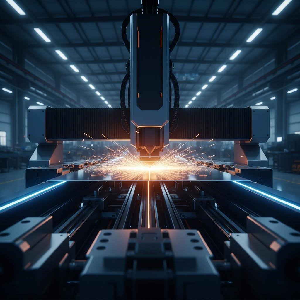
Tecnologia de Corte a Laser Explicada
Uma máquina de corte a laser concentra intensa energia luminosa para fundir, queimar ou vaporizar o material ao longo de um trajeto programado. O resultado? Cortes excepcionalmente limpos com mínimo processamento pós-corte em materiais de espessura fina a média. Quando seu projeto exige formas intrincadas, furos pequenos ou tolerâncias rigorosas, o corte a laser de precisão entrega resultados que outros métodos simplesmente não conseguem igualar.
Mas aqui está algo que muitos engenheiros não percebem: nem todo corte a laser é igual. As duas tecnologias dominantes — lasers a CO₂ e lasers de fibra — atendem a propósitos fundamentalmente distintos.
Laser de CO2 emitem luz com comprimento de onda de 10,6 µm e se destacam com materiais não metálicos como acrílico, madeira, couro e certos plásticos. Também lidam eficazmente com chapas metálicas mais espessas (10-20 mm ou mais), especialmente quando combinadas com assistência de oxigênio para um processamento mais rápido. No entanto, os sistemas a CO2 consomem consideravelmente mais energia — operando com apenas 5-10% de eficiência — o que aumenta significativamente os custos operacionais.
Lasers de fibra operam com comprimento de onda de 1064 nm e dominam as aplicações de corte de metais. De acordo com a comparação técnica da Xometry, os lasers de fibra oferecem aproximadamente 3 a 5 vezes a produtividade de máquinas a CO2 de capacidade semelhante em trabalhos adequados. Sua eficiência excede 90%, o que significa custos elétricos drasticamente menores. Além disso, os serviços de corte a laser de fibra normalmente alcançam uma vida útil de 25.000 horas — dez vezes mais que as alternativas a CO2.
Para metais reflexivos como alumínio, latão e aço inoxidável, os sistemas a laser de fibra lidam com esses materiais desafiadores sem os problemas de reflexão que afetam a mais antiga tecnologia CO2. A contrapartida? Custos iniciais mais altos de equipamentos — às vezes de 5 a 10 vezes mais caros do que sistemas CO2 equivalentes.
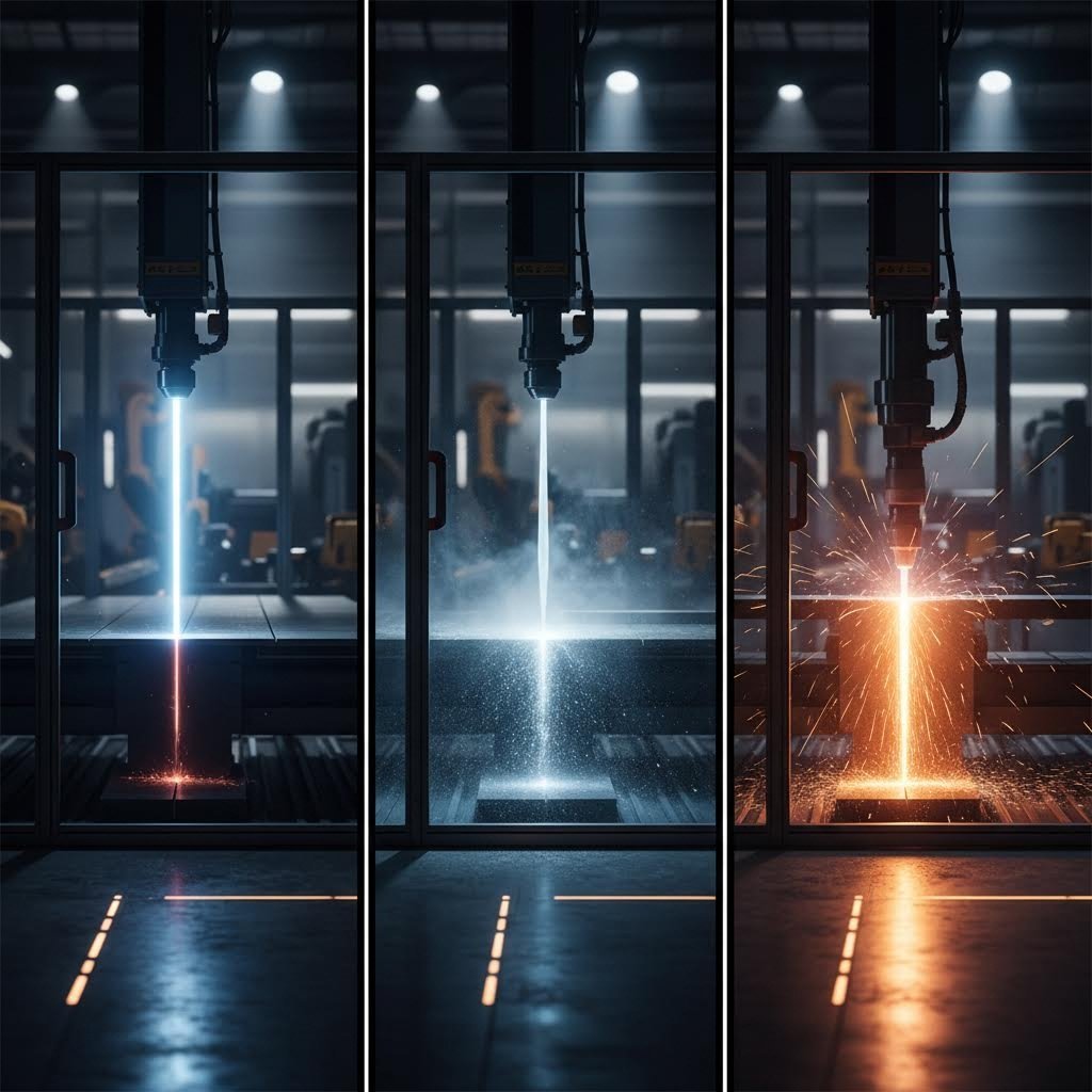
Alternativas de Corte por Jato de Água e Plasma
Quando o calor se torna o inimigo, o corte por jato d'água entra em ação. Esse processo de corte a frio utiliza água de alta pressão (frequentemente entre 60.000 e 90.000 PSI) misturada com partículas abrasivas de granada para cortar praticamente qualquer material sem distorção térmica.
Por que isso é importante? As zonas afetadas pelo calor podem alterar as propriedades do material, causar empenamento e exigir tratamentos adicionais de revenimento. O corte por jato d'água elimina completamente essas preocupações. Para suportes de titânio aeroespaciais, aços-ferramenta tratados termicamente ou materiais onde a integridade da microestrutura é crítica, o corte por jato d'água torna-se a única opção viável.
A versatilidade vai além dos metais. Pedra, vidro, compósitos e produtos alimentícios — o corte por jato d'água lida com todos eles. Projeções do setor indicam que o mercado de corte por jato d'água alcançará mais de 2,39 bilhões de dólares até 2034 , impulsionado pela demanda por corte sem calor em diversas indústrias.
Corte de plasma adota uma abordagem oposta, utilizando um arco elétrico e gás comprimido para criar temperaturas superiores a 20.000°C. Isso faz do plasma o campeão de velocidade para metais condutivos espessos. Cortar aço de 1 polegada? O plasma processa aproximadamente 3 a 4 vezes mais rápido que o jato d'água, com custos operacionais cerca de metade por pé linear.
A desvantagem é a precisão. As tolerâncias do plasma variam entre ±0,5 e ±1,5 mm — aceitáveis para fabricação estrutural, construção naval e equipamentos pesados, mas insuficientes para montagens com tolerâncias rigorosas.
Cisalhamento Mecânico para Trabalhos de Alto Volume
Às vezes, a solução mais simples funciona melhor. O corte mecânico utiliza lâminas opostas — como uma tesoura industrial — para realizar cortes retos em chapas metálicas. Sem consumíveis, sem calor, apenas força mecânica limpa.
Para operações de corte em grande volume, nas quais são necessários milhares de peças retangulares ou quadradas, o corte mecânico oferece velocidade e eficiência de custo incomparáveis. Esse processo trabalha materiais com espessura de até aproximadamente 12 mm, mantendo tolerâncias entre ±0,1 mm e ±0,5 mm, conforme o estado das lâminas e as propriedades do material.
A limitação? A geometria. O corte mecânico produz apenas cortes retos. Formas complexas, curvas ou recursos internos exigem outros métodos.
Sistemas CNC Router complementam as opções para aplicações específicas. Embora estejam principalmente associados à madeira, plásticos e compósitos, o fresamento CNC também processa metais mais macios, como o alumínio, desde que equipado com ferramentas adequadas. Esses sistemas destacam-se no processamento de peças de grande formato e materiais nos quais uma máquina de corte por matriz poderia ser excessiva.
Os serviços de corte a laser para tubos representam uma variação especializada que vale a pena mencionar — esses sistemas giram perfis tubulares enquanto a cabeça do laser traça padrões complexos, permitindo recursos que seriam impossíveis com métodos de chapa plana apenas.
Comparação Abrangente de Métodos
Como você transforma tudo isso em decisões práticas? A comparação a seguir detalha cada tecnologia de corte de metal nos fatores mais relevantes para os seus projetos:
| Fator | Laser (Fibra) | Jato de Água | Plasma | Tosa | Roteamento CNC |
|---|---|---|---|---|---|
| Compatibilidade dos materiais | A maioria dos metais, especialmente os reflexivos | Qualquer material exceto vidro temperado | Apenas metais condutores | Chapas metálicas até 12 mm | Metais macios, plásticos, compósitos |
| Faixa de espessura | Até 25 mm (a precisão diminui acima de 20 mm) | Até 200 mm com precisão consistente | capacidade de 100 mm ou superior | Até 12 mm | Varia conforme a dureza do material |
| Tolerâncias precisas | ±0,05 a ±0,1 mm | ±0,03 a ±0,08 mm | ±0,5 a ±1,5 mm | ±0,1 a ±0,5 mm | ±0,1 a ±0,25 mm |
| Qualidade da Borda | Excelente, rebarba mínima | Excelente, sem zona afetada pelo calor | Boa, pode exigir limpeza | Boa em materiais finos | Bom, pode exigir rebarbação |
| Velocidade de Processamento | Muito rápido em materiais finos | Mais lenta, especialmente em materiais espessos | Rápido em metais espessos | Muito rápida para cortes retos | Moderado |
| Custo do equipamento | Alta (~$90K-$500K+) | Muito alta (~$195K+) | Moderada (~$90K) | Baixo a moderado | Moderado |
| Custo operacional | Baixo (alta eficiência) | Moderado (consumo abrasivo) | Baixo por pé | Muito Baixo | Baixa |
| Melhor Aplicação | Peças de precisão, designs intrincados | Materiais sensíveis ao calor, precisão máxima | Aço estrutural, chapas grossas | Corte em grande volume | Formato grande, materiais macios |
O quadro de decisões torna-se mais claro quando você se concentra nas suas restrições específicas. Precisa de serviços de corte a laser de fibra para metais reflexivos com menos de 20 mm? O laser é a sua resposta. Requer um processo livre de calor para ligas aeroespaciais? O jato d'água é a solução. Fabricação de componentes estruturais em aço onde a velocidade é mais importante que a precisão? O plasma faz sentido do ponto de vista econômico.
Compreender essas diferenças posiciona você para ter conversas informadas com prestadores de serviços — e, mais importante, para evitar pagar por capacidades que o seu projeto realmente não necessita. A próxima decisão crítica? Associar a tecnologia escolhida ao material específico que você está cortando.
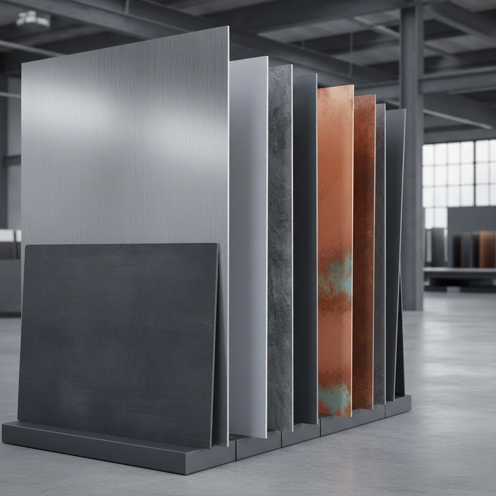
Guia de Seleção de Materiais para Resultados Ótimos de Corte
Você identificou a tecnologia de corte correta—mas aqui está o desafio: essa decisão não significa nada se você não levar em conta o que está realmente cortando. As mesmas configurações de laser que produzem bordas impecáveis em aço carbono podem destruir um chapa de Aço Inoxidável ou criar rebarba excessiva em alumínio. As propriedades do material ditam tudo, desde a velocidade de corte até a qualidade da borda e se suas peças chegam dentro da tolerância.
Compreender como diferentes metais se comportam sob forças de corte, exposição ao calor e jatos abrasivos ajuda você a especificar o processo correto desde o início. Vamos analisar as principais categorias de materiais e o que torna cada uma delas única.
Considerações sobre o Corte de Aço e Aço Inoxidável
Os metais ferrosos continuam sendo a base dos projetos de fabricação de metais em todo o mundo. O aço carbono, o aço inoxidável e ligas especiais como o AR500 apresentam características de corte distintas que influenciam a seleção do método.
Aço Carbono (Aço Doce) é o material mais tolerante para operações de corte. Sua resistência à tração moderada (tipicamente 400-550 MPa) e condutividade térmica tornam-no compatível com praticamente todos os métodos de corte. O corte a laser destaca-se aqui, especialmente com gás assistente de oxigênio que acelera a reação de corte em chapas de aço mais espessas. O plasma lida eficientemente com chapas pesadas, enquanto o cisalhamento funciona perfeitamente para operações de recorte em alto volume.
Aço Inoxidável introduz complexidade. De acordo com A análise técnica da Universal Tool , o aço inoxidável produz bordas limpas e de alta qualidade ao usar lasers de fibra, mesmo em espessuras maiores — tornando-o um excelente candidato para trabalhos de precisão. No entanto, a menor condutividade térmica do material em comparação com o aço carbono faz com que o calor se concentre na zona de corte, exigindo ajustes cuidadosos nos parâmetros para evitar descoloração e deformação.
o aço inoxidável 316 merece menção especial. Esta liga de cromo-níquel-molibdênio oferece resistência à corrosão superior, mas corta aproximadamente 15-20% mais devagar que os graus padrão 304 devido ao seu maior teor de níquel. Ao especificar o corte para aplicações marítimas, processamento químico ou médicas, considere essa diferença de velocidade nas suas expectativas de cronograma.
Aço AR500 representa o extremo mais desafiador do espectro. Com dureza Brinell variando de 470 a 500 HB e resistência à tração excedendo 1.380 MPa, esta liga resistente à abrasão exige abordagens especializadas. De acordo com A documentação técnica da Metal Zenith , o corte por plasma lida efetivamente com o AR500 em blindagem, equipamentos de mineração e componentes de máquinas pesadas. O corte a laser funciona, mas requer velocidades mais baixas e configurações de potência mais altas. O jato de água permanece a opção preferida quando as zonas afetadas pelo calor precisam ser completamente eliminadas — essencial em aplicações onde a dureza do aço não pode ser comprometida.
Aqui estão os métodos de corte ideais para materiais ferrosos:
- Aço Carbono (até 25 mm): Laser de fibra com oxigênio auxiliar, plasma para chapas grossas, cisalhamento para brancos
- Folha de Aço Inoxidável: Laser de fibra com nitrogênio auxiliar (previne oxidação), jato de água para graus sensíveis ao calor
- AR500 e Aços Temperados: Jato de água (sem zona afetada pelo calor), plasma (custo-efetivo para seções grossas)
Desafios com Alumínio e Metais Macios
Metais não ferrosos comportam-se fundamentalmente diferente sob operações de corte. Sua alta condutividade térmica, pontos de fusão mais baixos e superfícies reflexivas criam desafios que exigem estratégias ajustadas.
Chapa de alumínio exemplifica essas dificuldades. A condutividade térmica do material—aproximadamente 205 W/m·K comparado aos 50 W/m·K do aço—significa que o calor se dissipa rapidamente da zona de corte. Isso parece benéfico, mas na verdade exige uma entrada de energia significativamente maior para manter a temperatura de corte. Muita potência causa fusão e formação de rebarbas; pouca potência resulta em cortes incompletos.
O problema da refletividade foi amplamente resolvido pela tecnologia moderna. Conforme observado pela Universal Tool, os lasers de fibra lidam excepcionalmente bem com o alumínio apesar de suas propriedades reflexivas — uma capacidade com a qual os lasers CO2 mais antigos tinham dificuldade. A chave é usar gás auxiliar de nitrogênio para prevenir a oxidação na borda cortada, o que criaria de outra forma uma superfície áspera e descolorida inadequada para aplicações visíveis ou acabamentos em alumínio anodizado.
De cobre e latão apresentam desafios ainda maiores devido à sua condutividade térmica extrema e alta refletividade. Métodos tradicionais de corte frequentemente tinham dificuldades com esses materiais, mas a tecnologia a laser de fibra mudou esse cenário. Ao comparar latão e bronze para a sua aplicação, lembre-se de que o latão (liga cobre-zinco) corta de maneira mais previsível do que o bronze (liga cobre-estanho), devido à sua composição mais consistente. Ambos exigem lasers de fibra de alta precisão operando em parâmetros específicos para obter resultados limpos.
Métodos ideais de corte para materiais não ferrosos:
- Alumínio (chapas finas a médias): Laser de fibra com assistência de nitrogênio, jato d'água para seções espessas ou ligas sensíveis ao calor
- Cobre: Laser de fibra de alta potência com configurações especializadas, jato d'água para materiais espessos
- - Em latão: Laser de fibra para trabalhos de precisão, jato d'água para manter o acabamento superficial
Ligas Especiais e Materiais Exóticos
Além dos metais comuns, certas aplicações exigem ligas especiais nas quais a seleção do método de corte se torna ainda mais crítica.
Titânio oferece a maior relação resistência-peso entre os metais de engenharia comuns, mas também o preço mais alto. Sua baixa condutividade térmica concentra o calor na zona de corte, enquanto sua reatividade com oxigênio em altas temperaturas cria riscos de oxidação. O corte a laser funciona com proteção por gás inerte, mas o jato d'água permanece como padrão ouro para componentes aeroespaciais de titânio, onde a integridade da microestrutura não pode ser comprometida.
Ligas de Níquel (Inconel, Hastelloy) utilizado em ambientes de alta temperatura e corrosivos que exigem corte por jato d'água ou corte a laser especializado. Esses materiais endurecem rapidamente durante a usinagem, tornando difícil a usinagem convencional após o corte.
A tabela abaixo resume como as principais propriedades do material influenciam as decisões dos parâmetros de corte:
| Propriedade do Material | Impacto no Corte | Ajuste necessário |
|---|---|---|
| Alta resistência à tração | Força/energia de corte aumentada necessária | Potência mais alta, velocidades de avanço mais lentas |
| Alta Condutividade Térmica | Calor dissipado da zona de corte | Entrada de potência aumentada, processamento mais rápido |
| Ponto de Fusão Baixo | Risco de fusão e formação de rebarbas | Potência reduzida, gás auxiliar otimizado |
| Alta refletividade | Reflexão da energia a laser (sistemas CO2) | Utiliza tecnologia a laser de fibra |
| Dureza (acima de 400 HB) | Desgaste acelerado de ferramentas/consumíveis | Jato de água preferido, ajuste as expectativas |
A espessura do material acrescenta outra variável. A maioria dos sistemas a laser processa metais ferrosos até 25 mm com eficácia, com precisão que degrada acima de 20 mm. As capacidades para alumínio geralmente atingem no máximo cerca de 12-15 mm para cortes de qualidade. O AR500 e os aços temperados podem exigir plasma ou jato de água em seções superiores a 10 mm, onde o laser produziria zonas afetadas pelo calor excessivas.
Ao especificar o seu serviço de corte de chapa metálica, comunique claramente tanto a classe do material como a espessura. Um pedido de "aço inoxidável" não fornece ao fabricante informações suficientes — especificar "aço inoxidável 316, espessura de 3 mm" permite a seleção correta do método e precificação precisa. Essa precisão na comunicação torna-se ainda mais importante ao analisarmos as especificações de tolerâncias e os padrões de qualidade das bordas que definem resultados bem-sucedidos no corte.
Explicação sobre Tolerâncias e Padrões de Qualidade de Borda
Parece complexo? Eis a realidade: seu método de corte pode produzir peças que parecem perfeitas, mas não conseguem ser montadas. Por quê? Porque as tolerâncias — o desvio aceitável em relação às dimensões especificadas — variam drasticamente entre as tecnologias. Compreender essas especificações é o que separa projetos bem-sucedidos de retrabalhos custosos.
Quando você consulta uma tabela de calibres de chapa metálica e especifica uma espessura de aço de 14 calibres (aproximadamente 1,9 mm) para seus suportes, também está assumindo as capacidades de tolerância do processo de corte que escolher. Vamos decifrar o que essas especificações significam realmente para os seus projetos.
Compreensão das Especificações de Tolerância
Na fabricação de precisão, tolerância define a quantidade aceitável de variação ao processar uma peça. Pense nisso como a folga permitida entre a sua intenção de projeto e a realidade física. Tolerâncias mais rigorosas significam que as peças se encaixam com maior precisão — mas também custam mais para serem alcançadas.
De acordo com Especificações técnicas da A-Laser , diferentes tecnologias de corte alcançam níveis de precisão muito distintos:
| Tecnologia de corte | Intervalo de tolerância típico | Melhores Aplicações |
|---|---|---|
| Laser UV | ±0,0005" (±0,0127 mm) | Componentes de microprecisão, dispositivos médicos |
| Laser de fibra | ±0,001" (±0,025 mm) | Peças de precisão em aço inoxidável |
| Laser CO2 | ±0,002" (±0,05 mm) | Fabricação Geral de Metais |
| Jato de Água | ±0,005" a ±0,010" (±0,127–0,254 mm) | Materiais sensíveis ao calor, seções espessas |
| Estampagem | ±0,005" a ±0,010" (±0,127–0,254 mm) | Produção em Grande Volume |
| Plasma | ±0,020" a ±0,060" (±0,5–1,5 mm) | Aço estrutural, chapas grossas |
Eis o que muitos projetistas deixam de perceber: esses valores representam cenários ideais em elementos planos. Quando seu projeto inclui dobras, a situação quanto às tolerâncias muda drasticamente. À medida que A Protolabs explica , ao atravessar cada dobra, introduz-se uma variação adicional — aproximadamente ±0,030" de tolerância linear mais 1° de tolerância angular por dobra. Quatro dobras entre os furos de fixação? Você agora está lidando com tolerâncias acumuladas que podem superar em 5 a 10 vezes sua precisão original de corte.
O que você pode fazer a respeito disso? Considere aumentar o diâmetro dos furos de fixação para acomodar eventuais desalinhamentos ou especifique componentes de fixação flutuantes que se autoajustem durante a montagem. Essas escolhas de projeto efetivamente eliminam as preocupações relacionadas às tolerâncias acumuladas, mantendo ao mesmo tempo o desempenho funcional.
Qualidade das Bordas e Expectativas de Acabamento Superficial
Além da precisão dimensional, a qualidade das bordas determina se suas peças exigem acabamento secundário ou seguem diretamente para a montagem. Três fatores críticos definem a qualidade das bordas: características do corte (kerf), efeitos térmicos e contaminação da superfície.
Corte refere-se à largura do material removido durante o corte — essencialmente, a "ranhura" criada pelo processo de corte. O corte a laser produz ranhuras estreitas (normalmente de 0,1 a 0,3 mm para lasers de fibra), enquanto o plasma gera ranhuras mais largas (1,5 a 3 mm ou mais). Por que isso é importante? Uma ranhura estreita significa menos desperdício de material e maior capacidade de encaixar peças mais próximas umas das outras, reduzindo seus custos por peça. Para designs intrincados com espaçamento apertado entre os detalhes, a largura da ranhura limita diretamente o que é geometricamente viável.
Ao trabalhar com espessura de aço de 11 gauge (aproximadamente 3 mm), as considerações sobre largura de corte tornam-se especialmente relevantes. Materiais mais espessos exigem mais energia e normalmente produzem cortes mais largos. Seu projeto deve levar isso em conta, mantendo espaçamento adequado entre os elementos.
Escória —definir rebarba simplesmente— é o metal ressolidificado que adere à borda inferior de um corte. Imagine material fundido escorrendo para baixo durante o corte, depois esfriando e aderindo à sua peça. Rebarba excessiva exige desbaste ou rebarbação antes da montagem, acrescentando tempo e custo. O corte a laser com parâmetros otimizados produz cortes praticamente livres de rebarba em materiais apropriados, enquanto o corte plasma normalmente deixa algum resíduo que requer limpeza.
O zona Termicamente Afetada (ZTA) representa a área adjacente ao corte onde as propriedades do material foram alteradas pela exposição térmica. Nesta zona, o metal sofre ciclos rápidos de aquecimento e resfriamento que podem alterar a dureza, reduzir a resistência à corrosão ou introduzir tensões internas. Em aços temperados, uma ZTA significativa pode amolecer o material exatamente onde se necessita mais resistência. Em aços inoxidáveis, pode reduzir a resistência à corrosão ao longo da borda do corte.
O corte por jato de água elimina completamente a ZTA, já que é um processo de corte a frio. O corte a laser minimiza a ZTA por meio de controle preciso da energia, enquanto o corte plasma cria as zonas mais afetadas devido às suas temperaturas extremas.
Compreender esses fatores de qualidade ajuda você a definir expectativas realistas ao solicitar orçamentos. Um suporte de precisão que exija tolerância de ±0,001" sem rebarbas em aço inoxidável 316 exige processamento a laser de fibra — e implica preços que refletem essas capacidades. Enquanto isso, componentes estruturais para conjuntos soldados frequentemente podem aceitar tolerâncias mais amplas e pequenos requisitos de limpeza, tornando o corte por plasma ou mesmo por cisalhamento economicamente viável.
Com as tolerâncias e a qualidade das bordas definidas, a próxima consideração é o que acontece após o corte — as operações secundárias que transformam peças cortadas em componentes acabados.
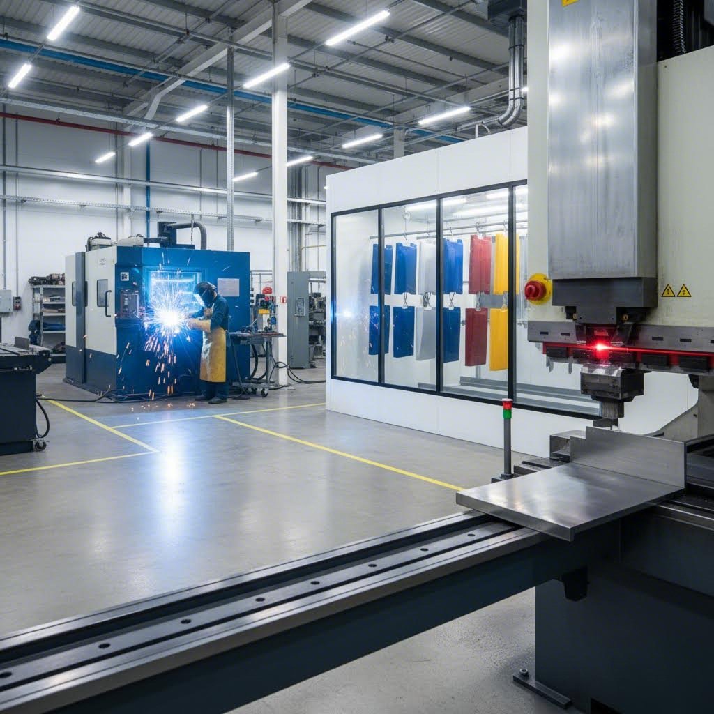
Além do Corte: Fluxos de Trabalho Completos de Fabricação
Suas peças acabaram de sair da mesa laser com bordas perfeitas e tolerâncias rigorosas. E agora? Para a maioria dos projetos, o corte representa apenas o primeiro capítulo de uma história de fabricação mais longa. O verdadeiro valor de um serviço abrangente de corte em chapa metálica surge quando se entende como o corte se integra a tudo o que vem depois — dobramento, inserção de hardware, soldagem e operações de acabamento que transformam peças planas em conjuntos funcionais.
Imagine pedir chapas cortadas a um fornecedor, enviá-las a outro para dobramento e a um terceiro para pintura a pó. Cada transferência introduz atrasos, riscos de qualidade e complicações logísticas. Uma aquisição inteligente consolida essas operações com fornecedores que gerenciam todo o fluxo de trabalho internamente.
Operações Secundárias Após o Corte
Uma vez concluído o corte, suas peças normalmente exigem processamento adicional antes de estarem prontas para uso. Essas operações secundárias agregam funcionalidade, melhoram a eficiência de montagem e preparam as superfícies para acabamento. De acordo com A visão geral de capacidades da Seconn Fabrication , consolidar esses processos com um único fornecedor reduz custos e acelera os tempos de entrega ao eliminar a coordenação entre múltiplos fornecedores.
A seguir estão as operações secundárias mais comuns que você encontrará:
- Dobragem e Conformação: Transforma chapas planas em formas tridimensionais utilizando dobradeiras ou equipamentos de curvatura
- Rosqueamento: Cria roscas internas em furos pré-cortados para fixação de elementos de união
- Escareamento: Chanfra as bordas dos furos para receber parafusos escareados
- Inserção de hardware: Insere encaixes roscados, espaçadores ou fixadores cativos em furos existentes — uma alternativa econômica à soldagem
- Aquecimento de água Une várias peças cortadas em conjuntos integrados por meio de processos de soldagem MIG, TIG ou por pontos
- Montagem: Combina componentes com fixadores, adesivos ou conexões mecânicas em unidades prontas para instalação
- Granilhação e Polimento: Aplica texturas superficiais consistentes ou acabamentos espelhados às superfícies visíveis
A inserção de componentes metálicos merece atenção especial. Este processo utiliza os furos criados durante o corte para posicionar com precisão os elementos de fixação prensados no metal. Por que escolher isso em vez da soldagem? Mantém uma precisão posicional mais rigorosa, elimina a distorção térmica e geralmente tem um custo menor para produção em grande volume. Quando o seu projeto exigir pontos de montagem roscados, superfícies para assentamento de juntas de borracha ou porcas presas, discuta as opções de inserção com o seu fabricante logo no início do processo de orçamento.
Integração de Dobra e Conformação
Aqui vai algo que muitos projetistas ignoram: suas tolerâncias de corte não significam nada se a dobragem introduzir variações imprevisíveis. A relação entre corte e dobragem é estreita — posições de furos, cortes de alívio de dobra e posicionamento de recursos dependem todos da compreensão do comportamento do material durante a conformação.
Oficinas de fabricação modernas utilizam equipamentos rolantes capazes de manipular várias espessuras de material. Por exemplo, dobradeiras de chapa com quatro rolos podem processar materiais com até aproximadamente 6 mm de espessura e criar cilindros com diâmetro de até 47 polegadas. Sistemas com três rolos manipulam materiais de bitola mais leve — normalmente até 11 gauge — para aplicações de menor diâmetro. Este equipamento permite invólucros curvos, carcaças cilíndricas e transições cônicas que seriam impossíveis apenas com operações de dobradeira mecânica.
Ao especificar peças que exigem corte e dobragem, considere estes fatores de integração:
- Correção de Dobra: O material se alonga durante a dobragem, afetando as dimensões finais — seu recorte plano deve levar isso em conta
- Direção do Grão: A dobragem perpendicular ao sentido de laminação reduz o risco de rachaduras
- Comprimento Mínimo da Aba Abas muito curtas não assentarão corretamente na dobradeira mecânica
- Proximidade de furos em relação a dobras: Recursos muito próximos das linhas de dobra distorcem durante a conformação
A soldagem de alumínio apresenta desafios únicos ao unir componentes de alumínio dobrados. A condutividade térmica do material e sua camada de óxido exigem técnicas especializadas—normalmente soldagem TIG com seleção adequada de metal de adição. Discuta esses requisitos previamente se sua montagem incluir seções de alumínio soldadas.
Opções de Acabamento de Superfície
O acabamento que você escolher protege suas peças contra corrosão, melhora a aparência e, às vezes, adiciona propriedades funcionais. Sua escolha depende do material base, do ambiente de operação e dos requisitos estéticos.
Pólvora acabamentos dominam a fabricação de metais por boas razões. Este pó seco aplicado eletrostaticamente—normalmente com formulações epóxi, poliéster ou híbridas—cura formando um revestimento durável que resiste a lascas, arranhões e desbotamento. Os serviços de pintura em pó oferecem centenas de opções de cores, diversas texturas que variam de brilho liso a fosco rugoso, e formulações especiais para exposição externa, resistência química ou propriedades antimicrobianas.
O processo funciona perfeitamente com aço e alumínio, mas exige uma preparação adequada da superfície. As peças devem ser limpas, por vezes fosfatadas ou cromatadas, e completamente secas antes da aplicação do revestimento. Os prazos de entrega normalmente acrescentam 2 a 5 dias, dependendo do tamanho dos lotes e dos requisitos de cor.
Anodizantes destina-se especificamente a componentes de alumínio. Este processo eletroquímico cria uma camada de óxido integrada que se torna parte do material base — e não um revestimento depositado sobre a superfície. O alumínio anodizado resiste à corrosão, aceita corantes para coloração e oferece excelente resistência ao desgaste em superfícies de alto contato. A anodização do Tipo II é indicada para aplicações decorativas, enquanto a anodização do Tipo III (revestimento duro) produz superfícies extremamente duráveis para componentes aeroespaciais, militares e industriais.
Outras opções de acabamento incluem:
- Eletrodoação: Deposita zinco, níquel ou cromo para proteção contra corrosão e aparência
- Passivação: Tratamento químico que potencializa a resistência natural à corrosão do aço inoxidável
- Pintura: Revestimentos líquidos aplicados para requisitos especializados ou pequenas quantidades
- Serigrafia: Adiciona logotipos, rótulos ou gráficos instrutivos diretamente nas superfícies acabadas
Ao avaliar fornecedores, pergunte se eles realizam os acabamentos internamente ou terceirizam para partes externas. Capacidades internas significam prazos mais rápidos e controle de qualidade unificado. A terceirização introduz manipulação adicional, riscos potenciais de danos e prazos mais longos — fatores que se agravam quando você está gerenciando cronogramas de produção apertados.
Compreender todo este fluxo de trabalho — desde o corte até operações secundárias e acabamento final — posiciona você para otimizar projetos quanto à facilidade de fabricação e selecionar parceiros que entreguem produtos verdadeiramente acabados, e não apenas peças cortadas. O próximo passo? Garantir que seus arquivos de projeto estabeleçam as bases para o sucesso desde o início.
Diretrizes de Projeto que Reduzem Custos e Erros
Você escolheu a tecnologia de corte e o material ideais para o seu projeto. Mas aqui está o problema — nada disso importa se o seu arquivo de design o colocar em uma situação de falha. A distância entre um furo e uma borda, a largura de uma aba de conexão, ou até mesmo como você nomeia as camadas do seu arquivo podem determinar se suas peças chegarão perfeitas ou exigirão retrabalho custoso.
Pense na preparação do projeto como a base que sustenta todo o resto. Faça corretamente, e o seu fornecedor de serviço de corte em chapa metálica entregará exatamente o que você imaginou. Faça errado, e você enfrentará atrasos, estouros de custo e peças que não se encaixam. Vamos analisar o que separa projetos bem-sucedidos daqueles problemáticos.
Essenciais de Projeto para Manufatura
Projetar para fabricabilidade (DFM) não se trata de limitar a criatividade — trata-se de compreender as realidades físicas. De acordo com a série Community College da SendCutSend, cada processo de corte possui limitações inerentes que ditam tamanhos mínimos de recursos, requisitos de espaçamento e limitações geométricas.
Tamanhos Mínimos de Recurso existem porque as ferramentas de corte—seja feixes a laser, jatos de água ou fresas—têm largura física. A largura do corte de um laser de fibra mede aproximadamente 0,1–0,3 mm, o que significa que recursos internos menores do que isso simplesmente não podem existir. A regra prática? Mantenha recortes internos e ranhuras com pelo menos 1,5 vezes a espessura do material ou a largura do corte, o que for maior.
Distância do Furo à Borda impede deformação durante o corte. Quando os furos estão muito próximos das bordas da peça, a concentração de calor ou tensão mecânica cria paredes finas que entortam, queimam ou rasgam. Um ponto de partida confiável: mantenha distâncias entre furos e bordas iguais a pelo menos a espessura do material. Para processos com alto calor, como corte a laser, aumente esse valor para 1,5–2 vezes a espessura, para garantir margens de segurança.
Distância da Ponte aplica-se ao cortar letras ou formas com "ilhas" internas — pense nos centros de letras como O, A ou R. Sem pontes de conexão, essas peças internas se soltam durante o corte. As pontes devem ter pelo menos 50% da espessura do material em largura, posicionadas onde serão menos visíveis após o acabamento.
Ao projetar para operações de dobragem, o Guia de projeto em chapa metálica Geomiq enfatiza a compreensão do fator K — a razão que descreve onde o eixo neutro está localizado dentro do material dobrado. Esse valor, normalmente entre 0,25 e 0,50, determina quanto o material se estica durante a conformação e afeta diretamente as dimensões do seu padrão plano. A maioria dos programas CAD inclui configurações de fator K, mas usar valores específicos do fabricante fornecidos pelo seu fabricante garante resultados precisos.
Perguntando-se como cortar plexiglass ou como cortar perspex para montagens de materiais mistos? Os mesmos princípios DFM se aplicam — tamanhos mínimos de recursos, seleção adequada de ferramentas e compreensão do comportamento do material sob forças de corte. O acrílico exige velocidades de avanço mais lentas e comprimentos de onda a laser específicos para evitar derretimento ou manchas nas bordas.
Práticas Recomendadas para Preparação de Arquivos
Seu projeto pode ser perfeito, mas um arquivo mal preparado cria confusão, atrasos e possíveis erros. Veja o que os fabricantes precisam de você:
Formatos de Arquivo Aceitos variam conforme o fornecedor, mas os padrões da indústria incluem:
- DXF (Drawing Exchange Format): O padrão universal para perfis de corte 2D — praticamente todos os serviços aceitam este formato
- STEP/STP: Preferido para modelos 3D que exigem dobramento ou interpretação de geometria complexa
- AI (Adobe Illustrator): Comum para trabalhos decorativos ou de sinalização
- PDF: Aceitável para perfis simples, embora PDFs baseados em vetores funcionem melhor do que versões rasterizadas
Etapas críticas de preparação de arquivos incluem converter todo o texto em contornos (fontes não são transferidas entre sistemas), remover linhas sobrepostas duplicadas que causam cortes duplos e garantir que toda a geometria forme polilinhas fechadas. Caminhos abertos ou lacunas no perfil de corte criam ambiguidade sobre o que está dentro ou fora da peça.
Dimensionamento e Unidades causam mais erros do que se poderia esperar. Sempre confirme se o seu arquivo utiliza polegadas ou milímetros — uma peça projetada com 100 mm que chega com 100 polegadas estraga o dia de todos. Inclua diretamente no arquivo ou na documentação acompanhante as dimensões principais e consulte uma tabela de tamanhos de brocas ao especificar diâmetros de furos, para garantir compatibilidade com ferramentas padrão.
Entender os tamanhos de calibre ajuda a comunicar claramente os requisitos de material. Em vez de presumir que o fabricante interpreta "calibre 16" da mesma forma que você (os sistemas de calibre para aço e alumínio são diferentes), especifique a espessura real em milímetros ou polegadas juntamente com a referência ao calibre.
Erros comuns a serem evitados
Antes de enviar seus arquivos, revise esta lista de verificação de design que abrange os erros que mais atrasam os projetos:
- Alívio insuficiente em dobras: Abas encontrando-se em cantos exigem cortes de alívio para evitar rachaduras—adicione fendas ou furos nos pontos de interseção
- Recursos muito próximos a dobras: Furos, fendas e abas se deformam quando posicionados a uma distância inferior a 2-3 vezes a espessura do material das linhas de dobra
- Ignorar a compensação de kerf: Seu modelo CAD mostra linhas de largura zero, mas cortes reais removem material—ajuste as dimensões críticas conforme necessário
- Esquecer folgas para componentes: Porcas press-fit, espaçadores e rebites precisam de distâncias mínimas até a borda e áreas planas para instalação
- Especificação excessiva de tolerâncias: Solicitar precisão de ±0,001" quando ±0,010" é suficiente aumenta drasticamente os custos
- Falta de observações sobre direção do grão: Para peças visíveis ou aplicações de dobramento, especifique se a orientação do grão é importante
- Considerações incompletas sobre encaixe: Peças que se encaixam eficientemente reduzem o desperdício de material — considere como suas formas se ajustam em tamanhos padrão de chapas
A comunicação com seu fabricante evita a maioria dos problemas antes que eles ocorram. Ao enviar projetos complexos, inclua uma breve descrição da aplicação, as dimensões críticas que devem manter tolerância e quaisquer operações secundárias necessárias. Pergunte se eles oferecem serviços de análise DFM — muitos fornecedores identificam problemas durante a cotação que, caso contrário, surgiriam durante a produção.
Qual é o retorno de um preparo minucioso do projeto? Orçamentos mais rápidos, peças protótipo precisas e execução de produção sem interrupções. Com seus arquivos otimizados, a última consideração passa a ser a seleção do parceiro certo para executar seu projeto — uma decisão que merece sua própria avaliação cuidadosa.
Como Avaliar e Selecionar o Parceiro de Corte Certo
Seus arquivos de projeto estão otimizados, seu material está especificado e você entende exatamente qual tecnologia de corte se adequa ao seu projeto. Agora chega a decisão que determinará se toda essa preparação valerá a pena: escolher o parceiro de fabricação certo. A escolha errada significa prazos perdidos, problemas de qualidade e falhas frustrantes de comunicação. A escolha certa? Peças que chegam conforme as especificações, no prazo e dentro do orçamento.
Encontrar uma fabricação metálica confiável perto de mim costumava significar dirigir por parques industriais e coletar cartões de visita. Hoje, você escolhe entre oficinas tradicionais com décadas de experiência e plataformas digitais que oferecem orçamentos instantâneos diretamente do seu navegador. Ambos os modelos funcionam — mas para tipos diferentes de projeto. Vamos criar um modelo para fazer a combinação ideal.
Avaliação das Capacidades do Provedor
Antes de solicitar orçamentos, você precisa entender o que separa fabricantes de aço adequados de parceiros excepcionais. De acordo com Guia de avaliação de Peças em Metal Fino , o processo de avaliação deve abranger as capacidades técnicas, sistemas de qualidade e fatores operacionais que afetam o sucesso do seu projeto.
Tecnologia e Equipamentos formam a base. O fornecedor opera com a tecnologia de corte exigida pelo seu projeto? Uma oficina especializada em corte a plasma não oferecerá a precisão necessária para uma aplicação com laser de fibra. Pergunte especificamente sobre fabricantes dos equipamentos, idade das máquinas e programas de manutenção. Equipamentos modernos com adequada manutenção produzem resultados consistentes; máquinas desatualizadas introduzem variabilidade.
O conhecimento especializado em materiais é igualmente importante. Eles conseguem manipular a sua liga específica, faixa de espessura e requisitos de acabamento superficial? Alguns fabricantes de metais especializam-se exclusivamente na fabricação de aço, enquanto outros mantêm estoque em dezenas de tipos de materiais. Se os seus projetos envolvem múltiplos materiais, verifique se eles possuem — ou podem obter — o necessário sem prazos de entrega prolongados.
Aqui estão as perguntas essenciais que você deve fazer aos fornecedores potenciais sobre suas capacidades:
- Quais tecnologias de corte vocês utilizam e quais são os limites de espessura?
- Vocês podem produzir um protótipo antes de se comprometer com quantidades de produção?
- Quais materiais vocês mantêm em estoque internamente e quais são adquiridos externamente?
- Quais são as tolerâncias típicas que vocês conseguem atingir com o meu tipo de material?
- Vocês oferecem operações secundárias como dobragem, roscamento e inserção de componentes?
- Como garantem a repetibilidade entre diferentes lotes de produção?
- Qual é a capacidade de produção de vocês e é possível escalar conforme minhas necessidades de volume?
A capacidade de prototipagem merece atenção especial. Como destaca a Thin Metal Parts, solicitar um protótipo — mesmo que inicialmente virtual — permite avaliar a qualidade antes de se comprometer com volumes de produção. Fornecedores que resistem à prototipagem ou exigem compromissos de produção completos desde o início podem não ter confiança em suas próprias capacidades.
Certificações importantes para garantia de qualidade
Certificações de qualidade indicam se um fornecedor opera com base em sistemas de gestão verificados ou simplesmente afirma "fazer trabalhos de qualidade". Para aplicações críticas, essas credenciais distinguem fornecedores qualificados de apostas arriscadas.
ISO 9001 representa o padrão básico de gestão da qualidade. Organizações certificadas demonstram processos documentados, foco no cliente e compromisso com melhoria contínua. De acordo com as orientações do setor, sempre verifique a certificação ISO quando seus produtos exigirem qualidade consistente — o que descreve praticamente todas as aplicações profissionais.
IATF 16949 amplia a ISO 9001 com requisitos específicos para o setor automotivo. Conforme explicado na visão geral de certificação da Xometry, essa estrutura foi desenvolvida pelo Grupo Internacional de Tarefas Automotivas (International Automotive Task Force) para garantir qualidade consistente ao longo da cadeia de suprimentos automotiva. A certificação IATF 16949 indica que um fabricante compreende a prevenção de defeitos, redução de variações e a documentação rigorosa exigida pelos fabricantes originais de equipamentos automotivos.
Por que isso é importante para o seu projeto de fabricação de aço? A certificação não é apenas burocracia — representa sistemas auditados que identificam problemas antes que cheguem ao seu pátio. Fornecedores certificados acompanham ações corretivas, mantêm equipamentos calibrados e treinam pessoal conforme padrões documentados. Essas práticas se traduzem diretamente em menos falhas de qualidade e resultados mais previsíveis.
Certificações adicionais a considerar com base no seu setor:
- ITAR (International Traffic in Arms Regulations): Exigido para fabricação relacionada à defesa, com rastreamento adequado de documentos
- AS9100: Gestão da qualidade aeroespacial que amplia a ISO 9001 com controles específicos do setor
- ISO 13485: Gestão da qualidade para dispositivos médicos em aplicações de saúde
Plataformas Online versus Oficinas Mecânicas Tradicionais
O cenário de fabricação se dividiu em dois modelos de serviço distintos, cada um otimizado para diferentes perfis de projeto. Compreender essa diferença ajuda você a escolher o parceiro certo mais rapidamente.
Plataformas online com orçamento instantâneo como OSH Cut e Send Cut Send transformaram a forma como engenheiros adquirem peças cortadas. De acordo com A comparação do OSH Cut , essas plataformas oferecem feedback de projeto no navegador, visualizações automáticas de nesting e transparência de preços que oficinas tradicionais simplesmente não conseguem igualar. Envie seu DXF, configure as opções e receba orçamentos em minutos, em vez de dias.
As vantagens são convincentes: OSH Cut mantém mais de 500 variações de materiais em estoque, fornece feedback imediato sobre fabricabilidade, incluindo simulações de dobramento, e garante prazos de entrega. Suas ferramentas de Projeto para Fabricabilidade detectam problemas antes do pedido — redimensionando automaticamente furos roscados, detectando problemas de deformação e identificando furos escareados automaticamente.
Ao comparar opções, a Send Cut Send oferece capacidades semelhantes de cotação instantânea, mas com algumas limitações. Os tamanhos máximos de peças, espessuras máximas para dobra e seleções de materiais variam entre as plataformas. A OSH Cut cotiza peças de até 119" x 59", enquanto concorrentes podem restringir a cotação instantânea a formatos menores. Para sequências complexas de dobras ou materiais mais espessos, verifique as capacidades antes de presumir que as plataformas online conseguem atender aos seus requisitos.
Oficinas tradicionais destacam-se onde as plataformas online atingem seus limites. Montagens complexas que exigem soldagem, materiais incomuns não mantidos em estoque por plataformas digitais e projetos que necessitam de consultoria técnica presencial costumam ser melhor atendidos por fabricantes locais experientes de estruturas metálicas. Essas oficinas podem levar mais tempo para emitir cotações, mas oferecem uma flexibilidade que os sistemas online padronizados não conseguem proporcionar.
O quadro decisório torna-se mais claro ao alinhar as características do projeto às vantagens de cada modelo de serviço:
| Característica do Projeto | Melhor Adequação: Plataforma Online | Melhor Adequação: Oficina Tradicional |
|---|---|---|
| Volume | Protótipos a médias tiragens | Produção em Alta Escala |
| Complexidade | Corte + dobra + acabamento simples | Montagens multioperação |
| Materiais | Metais padrão em estoque | Ligas especiais, pedidos especiais |
| Cronograma | Entrega rápida é crítica | Agendamento flexível aceitável |
| Apoio técnico | Ferramentas DFM de autoatendimento | Assistência consultiva em design |
| CERTIFICAÇÕES | Verificar por plataforma | Frequentemente certificado ISO/IATF |
Para protótipos rápidos em que você precisa de peças em dias em vez de semanas, plataformas online oferecem velocidade inigualável. Seus sistemas automatizados eliminam atrasos na cotação e gargalos no agendamento da produção. Mas quando seu projeto exige produção certificada IATF 16949 para aplicações automotivas, colaboração estreita em montagens complexas ou materiais fora dos catálogos padrão, fabricantes tradicionais de metal próximos a mim frequentemente oferecem soluções melhores.
Antes de finalizar qualquer parceria, solicite amostras de trabalhos semelhantes. Conforme recomenda a Thin Metal Parts, amostras físicas revelam níveis de qualidade que cotações e listas de capacidades não conseguem comunicar. Examine a qualidade das bordas, a precisão dimensional e a uniformidade do acabamento. Essas avaliações tangíveis informam mais sobre o que você realmente receberá do que qualquer material promocional poderia.
Com a sua estrutura de avaliação estabelecida, o próximo passo é compreender como essas capacidades de corte se traduzem em aplicações do mundo real — desde a validação de protótipos até a produção em larga escala.
Aplicações Industriais: De Prototipagem à Produção
Você já avaliou os fornecedores, otimizou seus projetos e selecionou a tecnologia de corte adequada. Mas é aqui que a teoria encontra a realidade: como essas capacidades se transformam em componentes reais para indústrias exigentes? A lacuna entre uma chapa metálica bem cortada e um suporte automotivo crítico para segurança não se resume apenas à precisão — trata-se de compreender os requisitos da aplicação e dimensionar processos capazes de entregar resultados consistentes em milhares de unidades.
De peças únicas para validação de protótipos até produções em série de dez mil chapas de aço, a jornada exige parceiros que compreendam as exigências específicas do seu setor. Vamos analisar como os serviços de corte de chapa metálica apoiam aplicações do mundo real, com foco especial no setor automotivo, onde os requisitos de qualidade atingem níveis mais rigorosos.
Aplicações Automotivas e de Transporte
O setor automotivo exemplifica onde a precisão no corte de chapas metálicas importa mais. A análise setorial da Prototek a fabricação de chapas metálicas é essencial para produzir peças veiculares resistentes, leves e bem projetadas—afetando desde o desempenho em segurança até a eficiência de combustível e o apelo estético.
Considere o que está em jogo: componentes do chassis absorvem energia em colisões, suportes da suspensão resistem a milhões de ciclos de estresse e conjuntos estruturais mantêm a integridade do veículo em condições extremas. Essas não são peças decorativas—são componentes críticos para a segurança, nos quais a qualidade do corte impacta diretamente na proteção dos ocupantes.
Aqui está como os serviços de fabricação de metais apoiam aplicações automotivas essenciais:
- Componentes do Chassi e da Estrutura: Chapas de aço inoxidável cortadas a laser fornecem a base para a integridade estrutural do veículo, exigindo tolerâncias precisas onde várias peças são soldadas juntas
- Peças de suspensão: Suportes, placas de montagem e reforços de braços de controle exigem precisão dimensional e qualidade consistente das bordas para um desempenho confiável contra fadiga
- Placas da carroceria: Portas, capôs, telhados e pára-lamas — normalmente cortados em alumínio ou aço — requerem bordas lisas que aceitem acabamentos sem necessidade de processamento adicional
- Componentes de motor: Protetores térmicos, suportes e tampas cortados em ligas especiais resistem a temperaturas extremas mantendo folgas precisas
- Estruturas internas: Fixações de painel de instrumentos, estruturas de assentos e suportes de sistemas de segurança exigem posicionamento preciso de furos para instalação de componentes
O sistema de escape ilustra a complexidade de múltiplos materiais. Tubos, silenciadores e carcaças de conversores catalíticos exigem cortes em materiais especificamente escolhidos pela resistência ao calor e à corrosão. Um carrinho de soldagem carregado com componentes destinados à montagem do sistema de escape pode incluir defletores em aço inoxidável, revestimentos em aço aluminizado e flanges em ligas especiais — cada um cortado com parâmetros otimizados para aquele material específico.
O que diferencia a fabricação automotiva do trabalho geral de metalurgia? Certificação. Conforme explica Smithers, a certificação IATF 16949 representa o compromisso da organização com qualidade e melhoria contínua na cadeia de suprimentos automotiva. Essa estrutura vai além da gestão básica da qualidade, incluindo prevenção de defeitos, redução de variações e rastreabilidade rigorosa exigida pelos fabricantes automotivos (OEMs).
Para chassis, suspensão e componentes estruturais onde falhas não são uma opção, fabricantes certificados pela IATF 16949 como Shaoyi (Ningbo) Tecnologia Metal oferecem a garantia de qualidade que as aplicações automotivas exigem. A combinação de capacidades de corte de precisão com operações integradas de estampagem e montagem cria um fluxo otimizado do projeto até componentes prontos para produção.
A fabricação moderna de automóveis também depende fortemente de rebites e fixações mecânicas, além da soldagem tradicional. Peças cortadas frequentemente incluem furos com posicionamento preciso para instalação de rebites, exigindo tolerâncias que assegurem resistência constante das juntas em produções de alto volume. A interação entre a precisão do corte e as operações subsequentes de montagem torna a seleção do parceiro um fator crítico.
Do protótipo à escala de produção
Aqui está uma realidade que muitos engenheiros descobrem tarde demais: um protótipo que funciona perfeitamente em quantidade um pode tornar-se um pesadelo na fabricação quando a produção atinge dez mil unidades. De acordo com O guia de escalonamento da All Metals Fabrication , pequenas escolhas de DFM invisíveis em protótipos únicos podem multiplicar custos, aumentar o tempo de ciclo e desestabilizar a produção quando se passa à produção em volume.
O desafio fundamental? Protótipos são otimizados para velocidade e forma — cortes a laser rápidos, abas dobradas à mão, tolerâncias mais folgadas. A produção precisa ser otimizada para repetibilidade, produtividade e custo por unidade. Superar esse hiato exige aquilo que os profissionais do setor chamam de mentalidade de "protótipo com intenção de produção".
Áreas típicas de incompatibilidade entre protótipo e produção incluem:
- Suposições de Tolerância: Protótipos acabados à mão ocultam variações que processos automatizados revelam
- Substituições de Material: Materiais de protótipo podem diferir das especificações de produção
- Diferenças de Processo: Métodos de corte em protótipos podem não ser economicamente escaláveis
- Requisitos de ferramentas: Volumes de produção podem justificar dispositivos dedicados que os protótipos não necessitavam
As capacidades de prototipagem rápida desempenham uma função essencial para além da simples produção de peças — elas permitem a validação do projeto antes do investimento em ferramental de produção. Quando é possível testar forma, ajuste e funcionalidade com peças cortadas realistas, em vez de aproximações impressas em 3D, identificam-se problemas que de outra forma surgiriam durante corridas de produção onerosas.
A vantagem de velocidade é enormemente importante. Prazos tradicionais de prototipagem de 2 a 4 semanas tornam os ciclos de projeto dolorosamente longos. Capacidades modernas — como a prototipagem rápida de 5 dias da Shaoyi, com resposta de orçamento em 12 horas — aceleram drasticamente os ciclos de iteração. O suporte abrangente em DFM detecta problemas de fabricabilidade já durante o orçamento, e não após o início da produção, evitando surpresas custosas que comprometem projetos.
Como é o sucesso na prática ao escalar operações? Considere estes princípios do guia da All Metals Fabrication:
- Projeto para Capacidade do Processo: Identifique a operação que se tornará seu gargalo e projete com base em suas capacidades, e não na perfeição
- Minimize as operações: Cada operação extra de rebarbação, soldagem de subconjunto ou acabamento multiplica o tempo de ciclo — otimize para reduzir ou combinar operações
- Padronize processos: Ao reduzir operações especiais, você simplifica o balanceamento da linha e diminui a variabilidade
- Implementar estratégia de fixação: Fixações modulares convertem chapas metálicas flexíveis em geometrias repetíveis e localizáveis para uma produção consistente
A inspeção do primeiro artigo (FAI) representa o passo crítico entre prototipagem e produção. Este processo de verificação comprova que seu processo e documentação produzem peças que atendem à intenção de projeto — incluindo evidências de material, etapas do processo, marcações e dados dimensionais. Trate a FAI como um evento formal, não como uma simples conferência, e você expandirá a produção de chapas metálicas com menos imprevistos.
O controle de revisão torna-se igualmente importante à medida que os volumes aumentam. Números principais de peças, modelos de ordens de mudança de engenharia (ECO) com matrizes de impacto e notificações automáticas para qualidade e aquisições após aprovação de revisão evitam a confusão que compromete os cronogramas de produção. Essas práticas administrativas parecem tediosas durante a prototipagem, mas tornam-se infraestrutura essencial em larga escala.
O caminho do conceito à produção em volume não exige sorte — exige processo. Aplique os princípios de DFM desde o início, faça protótipos com intenção de produção, escolha parceiros certificados com experiência em escalonamento e trate a transição como um programa gerenciado, e não como uma reflexão tardia. Faça isso, e você transformará chapas de aço em conjuntos prontos para produção com a previsibilidade exigida pelo seu programa.
Fazendo a Escolha Certa para o Seu Projeto de Corte de Metais
Você percorreu as tecnologias de corte, a ciência dos materiais, as especificações de tolerância e os frameworks de avaliação de fornecedores. Agora chegou o momento da decisão: transformar todo esse conhecimento em ação. Seja você comprando chapas de alumínio para invólucros de protótipos ou chapas metálicas para componentes estruturais em produção em larga escala, os princípios permanecem consistentes — associe a tecnologia aos requisitos, prepare os projetos com cuidado e parceie-se com fabricantes capacitados.
Associando Tecnologia aos Requisitos do Projeto
O framework de decisão que você desenvolveu ao longo deste guia resume-se em três variáveis principais: propriedades do material, exigências de precisão e volume de produção. Acerte nessas três, e todo o resto seguirá naturalmente.
O método ideal de corte de chapa metálica não é o mais avançado ou caro — é aquele que oferece a precisão necessária, no seu material, no seu volume e dentro do seu orçamento. Laser para precisão e velocidade em metais finos, jato d'água para aplicações sensíveis ao calor, plasma para aço estrutural grosso e cisalhamento para cortes em grande volume. Combine a ferramenta certa com a tarefa.
Ao procurar por chapa metálica perto de mim, lembre-se de que a proximidade geográfica importa menos do que a adequação de capacidades. Um fornecedor certificado em qualquer lugar do país, que entenda a sua aplicação, supera uma oficina local sem o equipamento ou conhecimento técnico adequado.
Considere como o seu projeto se encaixa na paisagem tecnológica:
- Validação de Protótipo: Priorize velocidade e flexibilidade — plataformas online com cotação imediata aceleram os ciclos de iteração
- Ampliação da Produção: Enfatize repetibilidade e certificação — IATF 16949 para automotivo, AS9100 para aeroespacial
- Conjuntos com materiais mistos: Procure fornecedores que lidem tanto com metais quanto com materiais como delrin ou componentes em folhas plásticas sob sistemas unificados de qualidade
- Placas metálicas personalizadas e trabalhos decorativos: Enfoque na qualidade das bordas e nas capacidades de acabamento, juntamente com a precisão do corte
Dando o Próximo Passo com Confiança
Seu próximo passo envolve três ações concretas: finalizar os arquivos de projeto utilizando os princípios DFM abordados anteriormente, solicitar orçamentos de fornecedores cujas capacidades atendam aos seus requisitos e validar a qualidade por meio de peças amostra antes de se comprometer com volumes de produção.
A preparação do projeto continua sendo sua atividade de maior impacto. De acordo com as orientações de fabricação da Zintilon, o impacto do seu método de corte vai além do corte imediato, influenciando operações subsequentes como dobragem, soldagem ou acabamento. Uma borda cortada de forma bruta com corte plasma pode exigir retificação adicional, acrescentando tempo e custo ao processo geral. Prepare arquivos que levem em conta essas considerações futuras.
Para leitores que exigem corte preciso de metais com capacidades integradas de estampagem e montagem, fabricantes como Shaoyi (Ningbo) Tecnologia Metal oferecem soluções abrangentes. Seu prazo de resposta de orçamentos em 12 horas e suporte DFM ajudam a otimizar projetos de manufatura desde o conceito inicial até a produção — especialmente valioso para aplicações automotivas onde a certificação IATF 16949 garante qualidade consistente em componentes de chassis, suspensão e estruturais.
O conhecimento que você adquiriu posiciona-o para fazer perguntas informadas, avaliar propostas criticamente e tomar decisões que equilibram qualidade, custo e cronograma. Solicite cortes de amostra para aplicações críticas. Verifique se as certificações atendem aos requisitos do seu setor. Confirme as capacidades de operações secundárias antes de dividir o trabalho entre múltiplos fornecedores.
Os serviços de corte de chapas metálicas constituem a base da fabricação moderna — mas apenas quando corretamente adequados às exigências do projeto. Munido deste entendimento abrangente sobre tecnologias, materiais, tolerâncias e critérios de avaliação de fornecedores, você está preparado para adquirir componentes que atendam às especificações, cheguem no prazo e se encaixem no seu orçamento. O próximo passo é seu.
Perguntas frequentes sobre serviços de corte de chapas metálicas
1. Quanto custa o corte de metal?
Os custos de corte de chapas metálicas geralmente variam entre $0,50 e $2 por polegada linear, dependendo do tipo de material, espessura e método de corte. As taxas por hora normalmente ficam entre $20 e $30, enquanto projetos completos de fabricação custam entre $4 e $48 por pé quadrado, conforme a complexidade da personalização. O corte a laser tem preços mais altos devido à precisão, enquanto o corte a plasma oferece soluções econômicas para aços estruturais espessos. Plataformas online fornecem orçamentos instantâneos, enquanto oficinas tradicionais podem exigir consulta para projetos complexos.
2. Como cortar peças grandes de chapa metálica?
Para peças grandes de chapa metálica, os serviços profissionais utilizam cortadoras a laser industriais, sistemas de corte por plasma ou máquinas de jato d'água, dependendo do material e dos requisitos de precisão. Os lasers de fibra processam chapas de até 119" x 59" com tolerâncias rigorosas, enquanto o corte por plasma é ideal para chapas espessas acima de 25 mm. Para aplicações caseiras, esmerilhadeiras angulares, furadeiras perfisadoras e serras circulares com lâminas para corte de metal são adequadas para projetos menores, embora os serviços profissionais garantam bordas mais limpas e maior precisão dimensional em aplicações críticas.
3. Quanto custa o trabalho com chapa metálica?
A fabricação completa de chapas metálicas varia de 4 a 48 dólares por pé quadrado, influenciada pela seleção de material, complexidade do corte, operações secundárias como dobragem e inserção de hardware, e requisitos de acabamento como pintura em pó ou anodização. Quantidades de protótipos custam mais por unidade do que volumes de produção devido aos requisitos de configuração. Fabricantes certificados pela IATF 16949 para aplicações automotivas podem exigir taxas mais altas, mas oferecem garantia de qualidade superior para componentes críticos de segurança.
4. Qual é a diferença entre corte a laser e corte por jato d'água para chapas metálicas?
O corte a laser utiliza energia luminosa focalizada para atingir tolerâncias de ±0,05–0,1 mm com excelente qualidade de borda, processando materiais finos a médios em altas velocidades. O corte a jato d’água emprega água sob alta pressão com abrasivos para corte a frio, eliminando zonas afetadas pelo calor e alcançando tolerâncias de ±0,03–0,08 mm em praticamente qualquer material com até 200 mm de espessura. Escolha o corte a laser para velocidade e precisão em metais convencionais; opte pelo corte a jato d’água quando for necessário evitar distorções térmicas ou ao cortar ligas aeroespaciais sensíveis ao calor.
5. Quais certificações devo procurar em um prestador de serviços de corte de chapas metálicas?
A certificação ISO 9001 estabelece padrões básicos de gestão da qualidade para resultados consistentes. Para aplicações automotivas, a certificação IATF 16949 é essencial, demonstrando os requisitos de prevenção de defeitos e rastreabilidade exigidos pelos fabricantes originais de equipamentos automotivos (OEMs). Projetos aeroespaciais exigem a certificação AS9100, enquanto a fabricação de dispositivos médicos requer conformidade com a norma ISO 13485. Trabalhos relacionados à defesa exigem o registro ITAR. Verifique sempre as certificações diretamente, em vez de confiar em declarações, pois os fornecedores certificados mantêm sistemas auditados que identificam problemas de qualidade antes do embarque das peças.