 Pequenas quantidades, altos padrões. Nosso serviço de prototipagem rápida torna a validação mais rápida e fácil —

CNC em Chapa Metálica Decodificado: 9 Processos, Tolerâncias e Fatores de Custo

O Que Significa Realmente Chapa Metálica CNC na Manufatura Moderna
Quando você ouve o termo "chapa metálica CNC", o que lhe vem à mente? Uma única máquina? Um processo específico de corte? Na realidade, representa uma categoria inteira de tecnologias de manufatura controladas por computador projetadas especificamente para transformar chapas metálicas planas em componentes de precisão. Ao contrário da usinagem CNC tradicional, que esculpe peças a partir de blocos sólidos de material, esses processos trabalham com chapas metálicas finas por meio de operações de corte, dobragem, perfuração e conformação.
Chapa metálica CNC refere-se ao conjunto completo de processos de controle numérico computadorizado que transformam chapas metálicas planas em peças acabadas por meio de operações programadas de corte, conformação e modelagem — incluindo corte a laser, corte a plasma, corte por jato d'água, punção CNC, dobragem em prensa-freio e sistemas automatizados de conformação.
De Chapa Plana a Peças Acabadas
Imagine começar com uma simples chapa plana de alumínio ou aço. Através dos processos de fabricação em chapa metálica , esse material torna-se um invólucro complexo, um suporte de precisão ou um componente de chassis automotivo. A jornada do material bruto até o produto acabado depende de instruções programadas que controlam cada corte, dobra e furo com notável precisão.
Aqui está o que torna essa abordagem distinta da usinagem convencional:
- A peça começa como uma chapa plana, ao invés de um bloco maciço
- O material é moldado por corte e conformação, ao invés de ser talhado
- Múltiplas operações frequentemente se combinam — corte primeiro, depois dobragem e montagem
- Geometrias ocas e planas são a saída principal
A Revolução Digital na Conformação de Metais
A fabricação tradicional de metais dependia fortemente de operadores qualificados que guiavam manualmente as ferramentas e tomavam decisões subjetivas. Hoje, softwares CAD e CAM permitem aos projetistas criar peças complexas digitalmente antes de enviar instruções precisas diretamente para as máquinas. Essa integração entre o software de projeto e os equipamentos de produção transformou o que é possível na fabricação de metais.
Sistemas CNC de corte em chapa metálica, por exemplo, podem executar padrões intricados com tolerâncias que métodos manuais simplesmente não conseguem igualar. Seja utilizando tecnologia a laser, plasma ou jato de água, o computador controla continuamente o percurso de corte, a velocidade e os ajustes de potência durante toda a operação.
Por Que o Controle por Computador Mudou Tudo
A transição para processos controlados por computador trouxe três vantagens fundamentais que redefiniram a indústria:
- Repetibilidade: Uma vez programadas, as máquinas produzem peças idênticas, quer você precise de dez ou de dez mil
- Precisão: O controle digital elimina a variabilidade inerente às operações manuais
- Velocidade: Sistemas automatizados operam continuamente com intervenção mínima
Para fabricantes dos setores automotivo, aeroespacial, eletrônico e inúmeros outros, essas capacidades significam produção mais rápida, menores taxas de erro e a possibilidade de criar componentes que seriam impossíveis apenas por métodos manuais. Compreender que a CNC para chapa metálica representa uma família de tecnologias — não uma única máquina — é o seu primeiro passo para selecionar o processo certo para qualquer projeto.
O Espectro Completo dos Processos de CNC para Chapa Metálica
Agora que você entende o que abrange a CNC para chapa metálica, provavelmente está se perguntando: qual processo devo realmente utilizar? A resposta depende do seu material, espessura, requisitos de precisão e objetivos de produção. Vamos analisar as seis principais tecnologias para que você possa visualizar todo o leque de opções disponíveis para transformar chapas metálicas em componentes acabados.
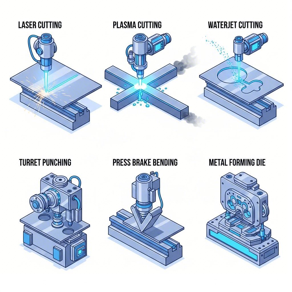
Tecnologias de Corte Comparadas
Quando se trata de separar materiais, três tecnologias principais dominam as operações de chapas metálicas em CNC. Cada uma utiliza um mecanismo fundamentalmente diferente para cortar a chapa metálica, e compreender essas diferenças ajuda a associar a ferramenta certa ao seu projeto.
Corte a laser: Um cortador a laser focaliza um feixe intenso de luz para derreter, queimar ou vaporizar o material ao longo de um trajeto programado. Esta tecnologia destaca-se na produção de designs complexos com qualidade excepcional de bordas em materiais de espessura fina a espessura média . Você encontrará o corte a laser ideal para peças detalhadas, tolerâncias rigorosas e aplicações nas quais as bordas limpas são mais importantes. O processo funciona perfeitamente em aço, aço inoxidável e alumínio com até cerca de 25 mm de espessura.
Corte por plasma: Este cortador de metal utiliza um gás eletricamente ionizado para gerar calor extremo, cortando materiais condutores rapidamente e com eficiência. Os sistemas a plasma lidam melhor com chapas metálicas mais espessas do que os lasers e têm menor custo operacional, embora sacrifiquem alguma qualidade de borda e precisão. Quando velocidade e custo são mais importantes do que detalhes ultrafinos, o plasma torna-se a escolha preferencial.
Corte por jato d'água: Imagine forçar água através de uma pequena abertura sob pressões superiores a 60.000 PSI, muitas vezes misturada com partículas abrasivas de granada. O resultado? Um jato de corte que corta praticamente qualquer material sem gerar calor. Esse processo de corte a frio elimina completamente as zonas afetadas pelo calor, sendo ideal para materiais sensíveis ao calor ou aplicações que exigem nenhuma distorção térmica.
Operações de Conformação e Dobra
O corte apenas leva você parcialmente até um componente acabado. A maioria das peças em chapa metálica requer dobragem ou conformação para atingir sua geometria final.
Prensas CNC: Essas máquinas aplicam força controlada por meio de um sistema de punção e matriz para criar dobras precisas em chapas planas. Dobradeiras modernas possuem réguas traseiras controladas por computador e sistemas de medição de ângulo que garantem resultados consistentes ao longo das séries de produção. O processo de dobragem transforma chapas cortadas bidimensionais em componentes tridimensionais, como suportes, carcaças e elementos estruturais.
Formação CNC: Além de dobras simples, equipamentos de formação especializados criam formas complexas por meio de operações de calandragem, estampagem e matrizes progressivas. Uma máquina de corte a matriz, por exemplo, pode produzir detalhes formados intrincados em um único golpe, tornando-a extremamente eficiente para a produção em grande volume de peças consistentes.
Sistemas de Perfuração e Puncionamento
Punção CNC: Prensas de punção com torreta possuem múltiplas formas de ferramentas e realizam ciclos rápidos de operações de punção para criar furos, rasgos, venezianas e outros recursos. Essas máquinas destacam-se na produção de padrões de características idênticas em grandes chapas metálicas. Para peças que exigem numerosos furos ou recortes repetitivos, a punção geralmente se mostra mais rápida e econômica do que as tecnologias de corte.
Aqui está a comparação completa que você precisa para tomar decisões informadas:
| Tipo de processo | Melhor Faixa de Espessura de Material | Tolerância Típica | Qualidade da Borda | Classificação de velocidade |
|---|---|---|---|---|
| Corte a laser | 0,5 mm – 25 mm | ±0,1 mm – ±0,25 mm | Excelente (superfície lisa, mínimo rebarbado) | Rápido para materiais finos |
| Corte de plasma | 3 mm – 50 mm+ | ±0,5 mm – ±1,5 mm | Boa (pode haver algum resíduo) | Muito rápido em materiais espessos |
| Corte a Jato D'Água | 0,5 mm – 150 mm+ | ±0,1 mm – ±0,25 mm | Excelente (sem zona afetada pelo calor) | Moderado |
| Furamento cnc | 0,5 mm – 6 mm | ±0,1 mm – ±0,2 mm | Boa (ligeiro arredondamento nas bordas) | Muito rápido para padrões de furos |
| Dobragem CNC | 0,5 mm – 20 mm | ângulo ±0,1° – ±0,5° | N/D (processo de conformação) | Rápido por dobra |
| Formação CNC | 0,3 mm – 10 mm | ±0,05 mm – ±0,2 mm | Bom a Excelente | Muito rápida (alto volume) |
Observe como cada tecnologia ocupa um nicho distinto? O corte a laser domina trabalhos de precisão em materiais mais finos, enquanto o plasma lida economicamente com aplicações de espessura pesada. O jato de água é único em situações sensíveis ao calor, e a punção permanece insuperável para padrões repetitivos de furos. Compreender essas diferenças posiciona você para selecionar o processo ideal — ou combinação de processos — para suas necessidades específicas.
É claro, saber qual processo funciona melhor também depende muito da escolha do material. Diferentes metais se comportam de maneira distinta sob cada tecnologia, o que nos leva à questão crítica da compatibilidade do material.
Diretrizes de Seleção de Material e Compatibilidade de Processo
Escolher o processo CNC certo para chapas metálicas não se trata apenas de espessura e tolerância — é igualmente sobre o material com o qual você está trabalhando. O alumínio comporta-se completamente diferente do aço inoxidável sob um feixe laser. O cobre apresenta desafios que o aço carbono nunca terá. Compreender esses comportamentos específicos dos materiais ajuda a evitar erros custosos e a selecionar processos que ofereçam resultados ideais.
Alumínio e suas preferências em CNC
A chapa de alumínio está entre os materiais mais adequados para usinagem CNC disponíveis. Sua excelente usinabilidade, propriedades leves e boa dissipação térmica tornam-no favorito em diversas indústrias. No entanto, a alta refletividade do alumínio exige considerações específicas nas operações de corte a laser.
Veja o que funciona melhor no processamento de chapas de alumínio:
- Corte a laser: Altamente eficaz, especialmente com lasers de fibra. Ligas como 6061 e 7075 são cortadas limpidamente, embora o alumínio puro exija mais atenção devido à sua maior refletividade
- Corte por jato d'água: Excelente escolha—ausência de zona afetada termicamente significa distorção térmica nula
- Corte por plasma: Funciona bem em alumínio mais espesso (6 mm ou mais), embora a qualidade da borda seja inferior à obtida por corte a laser
- Punção CNC: Ideal para padrões de furos; a maciez do alumínio permite operações de alta velocidade com desgaste mínimo da ferramenta
- Dobragem CNC: Exige atenção aos raios de dobragem para evitar rachaduras, especialmente com têmperas mais duras
Em relação à espessura, chapas de alumínio nas bitolas de 22 (0,64 mm) até 10 (3,4 mm) são facilmente trabalhadas na maioria dos processos. Chapas de alumínio mais espessas que 6 mm frequentemente se beneficiam mais do corte por jato d'água ou plasma do que por laser, em termos de eficiência de custos.
Tipos de Aço e Correspondência com Processos
O aço continua sendo o material principal na fabricação de chapas metálicas, mas nem todos os tipos de aço se comportam da mesma forma. O aço carbono, a chapa de aço inoxidável e a chapa galvanizada apresentam características únicas que influenciam a seleção do processo.
Aço Carbono: O material mais direto para operações CNC em chapa metálica. As chapas de aço carbono absorvem eficientemente a energia do laser, cortam limpo com plasma e dobram de forma previsível. Espessuras de chapa de aço de 16 gauge (1,5 mm) até 25 mm funcionam bem com sistemas a laser, enquanto chapas de aço mais pesadas costumam ser direcionadas ao corte a plasma para um processamento mais rápido.
- Corte a laser: Excelente em todas as espessuras até 25 mm
- Corte por plasma: Preferido para materiais mais espessos (12 mm+) onde a velocidade é mais importante que o acabamento da borda
- Punção CNC: Altamente eficaz para chapas finas que exigem múltiplos furos
- Dobragem CNC: Características previsíveis de retorno elástico tornam a programação simples
Chapa de Aço Inoxidável: Este material exige mais dos seus equipamentos. A tendência do aço inoxidável de encruar significa desgaste mais rápido das ferramentas, e sua menor condutividade térmica concentra calor na zona de corte. De acordo com especialistas em usinagem, o aço inoxidável requer alto torque do fuso, fixação adequada para reduzir vibrações e refrigeração abundante para controlar o acúmulo de calor.
- Corte a laser: Funciona bem, mas exige parâmetros ajustados — velocidades mais baixas, maior potência
- Corte por jato d'água: Excelente escolha para aços inoxidáveis espessos onde as preocupações com calor são relevantes
- Punção CNC: Eficaz, mas causa desgaste mais rápido da ferramenta do que o aço carbono
- Dobragem CNC: Requer compensação de pré-dobra devido à significativa recuperação elástica
Chapa Galvanizada: O revestimento de zinco adiciona complexidade. O corte a laser vaporiza o revestimento, criando fumos que exigem ventilação adequada. A boa notícia? A chapa de metal base corta de forma semelhante ao aço carbono padrão, uma vez considerado o revestimento.
Trabalhando com Metais Refletivos
Cobre e latão apresentam os ma maiores desafios nas operações CNC de chapas metálicas — especialmente no corte a laser. Esses materiais refletem a energia do laser de volta à fonte, em vez de absorvê-la para o corte. Como observam especialistas em corte a laser, o desafio principal no corte a laser de metais reflexivos decorre de suas superfícies altamente refletivas, nas quais parte da energia é refletida de volta à fonte do laser em vez de ser efetivamente absorvida.
Compatibilidade com Cobre:
- Corte a Laser de Fibra: Possível com sistemas de alta potência (4kW+) e configurações especializadas. O comprimento de onda mais curto dos lasers de fibra (1,07 µm) melhora a absorção em comparação com os lasers CO2
- Corte por jato d'água: O método preferido — sem preocupações com reflexão, excelente qualidade de borda
- Punção CNC: Eficiente para criar furos e padrões sem problemas de refletividade
- Dobragem CNC: Funciona bem; a ductilidade do cobre permite raios de dobra apertados
Compatibilidade com latão:
- Corte a laser: Desafios de refletividade semelhantes aos do cobre, embora ligeiramente mais fáceis de gerenciar
- Corte por jato d'água: Excelentes resultados sem preocupações térmicas
- Punção CNC: Ideal — a natureza autolubrificante do latão reduz o atrito e minimiza a formação de rebarbas
- Dobragem CNC: Boa conformabilidade com molação mínima
A percepção fundamental sobre metais reflexivos? Não force o corte a laser quando o jato de água ou punção oferecem resultados mais fáceis e consistentes. As propriedades do material devem orientar a seleção do processo, e não o contrário.
Compreender quais metais combinam bem com quais processos é essencial — mas igualmente importante é saber quais níveis de precisão cada combinação pode alcançar. Isso nos leva às especificações críticas relacionadas a tolerâncias, acabamentos superficiais e qualidade das bordas.
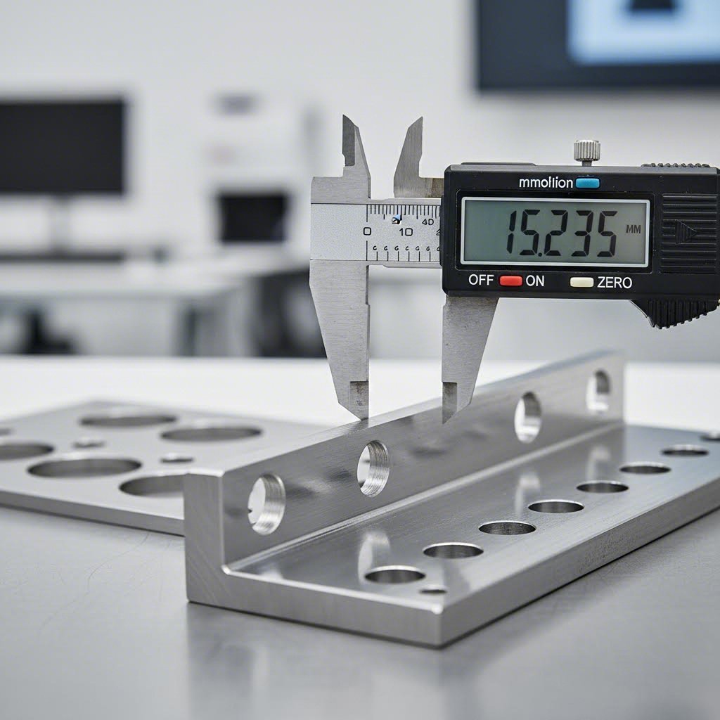
Explicação das Especificações de Precisão e Tolerância
Você já selecionou seu material e identificou os processos compatíveis — mas até que ponto é possível manter dimensões exatas? Essa pergunta é extremamente relevante ao projetar peças que devem se encaixar com precisão ou atender requisitos técnicos rigorosos. Compreender as especificações de tolerância ajuda você a definir expectativas realistas e evitar surpresas custosas quando as peças chegarem.
Faixas de Tolerância nas Diferentes Tecnologias
Diferentes processos CNC de chapa metálica alcançam níveis de precisão muito distintos. Uma peça cortada a laser e uma peça cortada a plasma feitas do mesmo material podem parecer semelhantes à primeira vista, mas sua precisão dimensional pode diferir significativamente. Veja o que você pode esperar realisticamente de cada tecnologia:
| Processo | Tolerância Linear Padrão | Tolerância de alta precisão | Tolerância de Diâmetro de Furo | Tolerância angular |
|---|---|---|---|---|
| Corte a laser | ±0,45mm | ±0,20 mm | ±0,08 mm a ±0,45 mm | N/A |
| Corte de plasma | ±0,5 mm a ±1,5 mm | ± 0,5 mm | ± 0,5 mm | N/A |
| Corte a Jato D'Água | ±0,1 mm a ±0,25 mm | ±0,1 mm | ±0,13 mm | N/A |
| Furamento cnc | ±0,1 mm a ±0,2 mm | ±0.05mm | ±0,1 mm | N/A |
| Dobragem CNC | ±0,45 mm (XYZ) | ±0,20 mm | N/A | ±0,5° a ±1,0° |
Observe como o corte a laser e o corte por jato d'água oferecem as tolerâncias mais rigorosas nas operações de corte, enquanto o corte a plasma sacrifica alguma precisão em favor da velocidade em materiais mais espessos. Para operações de dobragem, segundo diretrizes industriais de tolerância, as tolerâncias angulares normalmente variam entre ±0,5° e ±1°, embora esses valores possam variar conforme as propriedades do material e o método de fabricação.
A espessura do material também influencia as tolerâncias alcançáveis. As tolerâncias de corte a laser variam conforme as faixas de espessura:
- 0,5mm a 2,0mm: ±0,12mm em furos, maior precisão geral
- 2,0mm a 5,0mm: ±0,05mm a ±0,10mm em dimensões lineares
- 5,0mm a 10,0mm: ±0,10mm a ±0,25mm típico
- 10,0mm a 20,0mm: ±0,25mm a ±0,50mm esperado
Ao trabalhar com materiais mais espessos — por exemplo, chapa de aço de 11 gauge (aproximadamente 3mm) ou chapa de aço de 14 gauge (cerca de 1,9mm) — constata-se que o corte a laser mantém excelente precisão. Porém, ao se aproximar de espessuras maiores, o corte por plasma frequentemente torna-se mais prático, apesar de ter tolerâncias mais amplas.
Fatores de Qualidade do Acabamento Superficial
A tolerância não se refere apenas às dimensões — o acabamento superficial afeta a funcionalidade, a aparência e a necessidade de operações secundárias. O que determina o acabamento que você realmente obterá?
Calibração da Máquina: Mesmo os melhores equipamentos apresentam desvios ao longo do tempo. A calibração regular garante que as cabeças de corte mantenham o foco adequado, os ângulos de dobragem permaneçam consistentes e a precisão de posicionamento continue dentro das especificações. Oficinas que pulam as revisões de calibração muitas vezes se perguntam por que sua precisão diminui.
Comportamento do material: Metais diferentes respondem de maneira distinta à energia de corte. O aço laminado a frio produz cortes mais suaves do que o aço laminado a quente de espessura idêntica, devido à sua superfície refinada e menores tolerâncias de espessura. De acordo com as especificações de tolerância de material, o aço laminado a frio oferece tolerâncias de espessura mais rigorosas (±0,05 mm a ±0,22 mm, dependendo da bitola) em comparação com as alternativas laminadas a quente.
Efeitos Térmicos: Processos de corte baseados em calor criam zonas afetadas pelo calor (HAZ) ao longo das bordas cortadas. O corte a laser minimiza essa zona, mas não a elimina. O corte a plasma gera áreas HAZ maiores. Apenas o corte por jato d'água produz cortes verdadeiramente frios, sem impacto térmico — essencial ao trabalhar com ligas sensíveis ao calor ou quando as propriedades metalúrgicas devem permanecer inalteradas.
Condição das ferramentas: Matrizes de punção desgastadas criam rebarbas maiores. Ópticas a laser degradadas reduzem o foco do feixe. Bocais de jato d'água erodidos alargam o fluxo de corte. O desgaste das ferramentas afeta diretamente a precisão dimensional e a qualidade da borda, tornando essenciais os programas de manutenção para resultados consistentes.
Assim como você pode consultar uma tabela de tamanhos de brocas ou uma tabela de bitolas de brocas ao selecionar ferramentas para operações de furação, compreender esses fatores de acabamento superficial ajuda você a especificar os processos adequados para suas exigências de acabamento.
Características das Bordas por Processo
A qualidade da borda frequentemente determina se as peças precisam de acabamento adicional antes da montagem. Veja o que cada processo normalmente produz:
Corte a laser: Produz bordas lisas e livres de óxido na maioria dos materiais. Materiais finos apresentam quase nenhum efeito térmico visível. Cortes mais espessos podem exibir leves estrias, mas raramente exigem acabamento secundário para aplicações funcionais.
Corte por plasma: Cria uma borda mais dura e ligeiramente áspera, com escória visível (metal ressolidificado) na superfície inferior. A maioria das peças cortadas a plasma requer desbaste ou limpeza antes da soldagem ou montagem. O chanfro nas bordas é comum em cortes espessos.
Corte por jato d'água: Oferece qualidade de borda consistente independentemente do material. Uma aparência levemente fosca é normal, com mínima diferença entre os lados de entrada e saída. A ausência de zona afetada pelo calor significa que as propriedades do material permanecem inalteradas até a borda.
Punção CNC: Produz bordas características de perfuração com leve dobramento no lado da matriz e uma face de cisalhamento mais limpa no lado do punção. As rebarbas exigem atenção, especialmente em materiais mais macios como o alumínio.
Compreendendo o Kerf e o Planejamento Dimensional
Todo processo de corte remove material ao cortar — essa largura removida é chamada de kerf. Ignorar o kerf leva a peças com dimensões menores que o desejado, portanto, compreender esses valores ajuda você a projetar com precisão.
Comparando os diferentes métodos, as larguras de kerf nos cortes são assim:
- Corte a laser: Aproximadamente 0,3 mm — o menor kerf, permitindo encaixe apertado e máxima utilização do material
- Corte por jato d'água: Aproximadamente 0,9 mm — ainda relativamente estreito, excelente para trabalhos de precisão
- Corte a Chama/Oxi-combustível: Aproximadamente 1,1 mm — kerf moderado para aplicações em chapas grossas
- Corte por plasma: Aproximadamente 3,8 mm no mínimo — o kerf mais largo, exigindo maior compensação de deslocamento
De acordo com a análise de kerf de corte, o corte a laser produz o menor kerf, cerca de 0,3 mm, tornando-o o mais preciso ao comparar os métodos térmicos de corte. O kerf maior do plasma, de 3,8 mm ou mais, significa que os operadores da máquina devem deslocar o caminho de corte mais longe das bordas finais para atingir as dimensões desejadas.
Aqui está por que isso importa na prática: se você estiver cortando um quadrado de 600 mm de uma chapa metálica usando plasma, a máquina deve levar em conta essa largura de corte de 3,8 mm+. A linha de corte passa fora do contorno da peça final, e não sobre ele. Recortes internos funcionam ao contrário — a linha de corte passa dentro do contorno desenhado. A menor largura de corte do laser simplifica esses cálculos e permite um encaixe mais apertado de múltiplas peças numa única chapa.
A espessura do material também influencia a largura de corte. Materiais mais espessos exigem mais energia para o corte, o que geralmente resulta em frestas mais largas. Ao processar chapas grossas, leve em consideração essas variações para manter a precisão dimensional das peças acabadas.
Com as especificações de tolerância e fatores de precisão agora claros, você está pronto para tomar decisões informadas sobre qual processo atende melhor aos requisitos específicos do seu projeto. Vamos examinar como associar sistematicamente essas capacidades às suas necessidades de produção.
Como Escolher o Método CNC Correto para Chapa Metálica
Você já aprendeu sobre os processos, materiais e especificações de precisão — mas como você realmente decide qual abordagem se adapta ao seu projeto específico? É aí que muitos engenheiros e compradores enfrentam dificuldades. Gráficos comparativos ajudam, mas não indicam como ponderar fatores conflitantes quando o orçamento entra em conflito com requisitos de precisão, ou quando o volume de produção muda completamente a viabilidade econômica.
Vamos construir um framework prático que você possa aplicar a qualquer projeto de CNC em chapas metálicas.
Associar o Processo ao Volume de Produção
A quantidade produzida altera fundamentalmente quais processos fazem sentido economicamente. Uma máquina para cortar metal perfeita para protótipos pode tornar-se proibitivamente cara em larga escala — e vice-versa.
Veja como o volume normalmente influencia a seleção do processo:
- 1-50 peças (Prototipagem): Corte a laser e jato de água dominam. A ausência de ferramentas personalizadas significa tempo de resposta rápido e fácil iteração de design. A punção CNC funciona se você estiver usando formas de furos padrão já disponíveis na torreta
- 50-500 peças (Baixo Volume): O corte a laser continua sendo economicamente viável. A dobragem CNC executa operações de conformação de forma eficiente. Considere se operações secundárias, como soldagem, podem ser otimizadas
- 500-5.000 peças (Volume Médio): A punção CNC torna-se cada vez mais competitiva para peças com múltiplos furos ou características. De acordo com especialistas em fabricação, a estampagem manual começa a fazer sentido nesse limite, quando são exigidas tolerâncias rigorosas (±0,05 mm a 0,10 mm)
- 5.000+ peças (Alto Volume): A estampagem progressiva oferece o menor custo por peça, embora o investimento em ferramental varie entre $10.000 e $100.000+. O custo inicial compensa-se quando se produz dezenas de milhares de peças idênticas
A principal conclusão? Não se comprometa com um processo antes de conhecer suas reais necessidades de volume. O que pode parecer caro em quantidades de protótipo muitas vezes torna-se a única escolha sensata em escala de produção
Complexidade e Requisitos de Características
A geometria da peça influencia fortemente qual máquina de corte de metal CNC ou equipamento de conformação oferece os melhores resultados. Algumas características simplesmente não podem ser produzidas economicamente com certas tecnologias.
Quando o corte a laser supera o corte por plasma:
- As peças exigem contornos intrincados com raios pequenos
- São necessários furos pequenos (diâmetro menor que a espessura do material)
- A qualidade das bordas deve ser lisa, sem acabamento secundário
- A espessura do material permanece abaixo de 12 mm para aço
- Detalhes finos como gravuras, corroção ou números de série são necessários
Uma máquina CNC a laser para metal destaca-se nessas aplicações de precisão, proporcionando bordas limpas que muitas vezes não necessitam de pós-processamento. Testes realizados em ambas as tecnologias confirmam que o corte a laser mostra-se muito superior para peças que exigem furos pequenos, detalhes finos ou bordas lisas .
Quando o corte por plasma é melhor:
- Metais condutores espessos (12 mm+) dominam sua lista de materiais
- A velocidade é mais importante do que a perfeição da borda
- Restrições orçamentárias limitam as opções de equipamento
- As peças receberão acabamento secundário de qualquer forma (retificação, preparação para soldagem)
Quando o jato d'água é a única opção:
- Zonas afetadas pelo calor não podem ser toleradas (componentes aeroespaciais, materiais endurecidos)
- Você está cortando material extremamente espesso (até 150 mm+)
- Materiais não metálicos como pedra, vidro ou compósitos estão envolvidos
- As propriedades do material devem permanecer inalteradas até a borda do corte
- Metais reflexivos como cobre ou latão apresentam desafios de refletividade no corte a laser
Quando a punção oferece vantagens sobre o corte:
- As peças apresentam padrões repetitivos de furos ou formas padrão
- Os volumes de produção justificam o tempo de configuração da torreta
- São necessários recursos de conformação tridimensional, como bossas, venezianas ou alojamentos para cabeças de parafuso
- A espessura do material permanece abaixo de 6 mm
Seleção de Processo Orientada pelo Orçamento
As considerações de custo vão além da precificação óbvia por peça. Compreender a economia entre fabricação e usinagem — e o panorama completo de custos nas operações de fabricação e usinagem — evita surpresas caras.
Siga esta estrutura numerada quando o orçamento for o fator decisivo:
- Calcule o custo total do projeto, não apenas o custo de corte. Um processo de corte mais barato que exija acabamento secundário caro pode custar mais no geral. Bordas cortadas a plasma frequentemente precisam ser desbastadas antes da pintura eletrostática, acrescentando mão de obra e tempo
- Considere o investimento em ferramentas. A estampagem oferece o menor custo por peça em grandes volumes, mas a produção das ferramentas leva de 30 a 55 dias e custa milhares a centenas de milhares de dólares. Se o seu projeto puder sofrer alterações, evite compromissos com ferramentas
- Considere o aproveitamento do material. O corte a laser tem uma linha de corte estreita (0,3 mm), permitindo um encaixe mais apertado do que o plasma (3,8 mm+). Em grandes séries de produção, essa diferença no desperdício de material impacta significativamente o custo total
- Leve em conta operações secundárias. Se as peças exigirem dobramento após o corte, escolha processos de corte que produzam bordas compatíveis com os requisitos da sua dobradeira. Bordas endurecidas por trabalho de alguns processos podem exigir recozimento antes da conformação
- Avalie os custos relacionados ao prazo de entrega. O corte a laser e a dobragem CNC podem entregar amostras em menos de 5 dias. Só a ferramenta para estampagem leva de 30 a 55 dias antes do início da produção. Se o tempo para lançamento for importante, processos mais rápidos podem justificar custos mais altos por peça
- Compare a disponibilidade de equipamentos. Equipamentos de corte a laser e plasma estão amplamente disponíveis. A capacidade de corte por jato d'água pode ser mais difícil de encontrar, possivelmente limitando as opções de fornecedores e prolongando os prazos de entrega
Aqui está uma hierarquia prática de custos para cenários comuns:
| Cenário | Processo Mais Econômico | POR QUE |
|---|---|---|
| 10 suportes de protótipo, aço de 3 mm | Corte a laser + dobragem CNC | Sem custo de ferramental, entrega rápida, precisão excelente |
| 500 caixas com múltiplos furos | Puncionamento CNC + dobragem CNC | Velocidade de punção para furos, ferramental padrão disponível |
| 50 suportes aeroespaciais, liga sensível ao calor | Corte por jato d'água + dobragem CNC | Sem distorção térmica, propriedades do material preservadas |
| 25.000 suportes automotivos | Estampagem progressiva | Menor custo por peça absorve o investimento em ferramental |
| 200 peças, chapa de aço de 25 mm | Corte de plasma | Corte rápido de materiais espessos, qualidade de borda aceitável |
Lembre-se de que a seleção de processo raramente ocorre isoladamente. A maioria das peças acabadas combina múltiplas operações — corte seguido de dobragem, punção antes da conformação ou corte por jato d'água combinado com montagem soldada. A abordagem mais inteligente considera como cada operação afeta a próxima, otimizando todo o fluxo de trabalho em vez de etapas individuais.
Com sua estrutura de seleção de processos estabelecida, compreender como diferentes indústrias aplicam esses princípios revela padrões práticos que você pode adaptar aos seus próprios projetos.
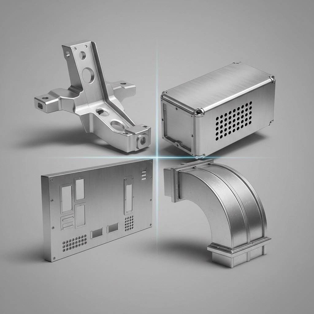
Aplicações Industriais de Automotiva a Eletrônica
Diferentes indústrias não utilizam apenas o CNC de chapa metálica de maneira distinta — elas priorizam características completamente diferentes. O que é mais importante na fabricação automotiva mal é considerado na produção de eletrônicos. Compreender esses requisitos específicos por setor ajuda você a especificar os processos corretos e encontrar fornecedores que realmente entendam sua aplicação.
Requisitos de Fabricação Automotiva
O setor automotivo exige uma combinação única de alto volume, tolerâncias rigorosas e consistência absoluta em lotes de produção que abrangem milhões de peças. Ao produzir componentes de chassis, suportes ou elementos estruturais, cada peça deve funcionar de forma idêntica em testes de colisão e sob estresse contínuo durante anos de uso viário.
Aplicações típicas de chapa metálica no setor automotivo incluem:
- Componentes Estruturais: Pisos, travessas e braçadeiras de reforço que formam a célula de segurança do veículo
- Elementos de chassis: Pontos de montagem da suspensão, componentes de subestrutura e conjuntos de berço do motor
- Peças body-in-white: Painéis internos de portas, reforços de teto e estruturas de pilares
- Suportes funcionais: Bandejas de bateria, suportes de sensores e fixações de chicotes elétricos
- Gestão de calor: Protetores de escapamento, tampas do túnel de transmissão e painéis de proteção inferior
O que realmente separa a fabricação de aço automotivo de outros setores? Os requisitos de certificação. A certificação IATF 16949 tornou-se a expectativa básica para fornecedores automotivos. Este padrão de gestão da qualidade vai muito além do ISO 9001 básico, exigindo rastreabilidade documentada, controle estatístico de processos e protocolos rigorosos de inspeção do primeiro artigo. Ao selecionar fabricantes de aço para aplicações automotivas, verifique seu status de certificação antes de discutir capacidades técnicas.
A seleção de materiais no setor automotivo também segue padrões específicos. Aços de alta resistência e baixa liga (HSLA) dominam as aplicações estruturais onde a redução de peso é importante. Chapas de alumínio aparecem cada vez mais em painéis de carroceria e fechamentos em veículos premium. Revestimentos galvanizados protegem contra corrosão durante toda a vida útil do veículo.
Padrões de Precisão Aeronáuticos
Se a indústria automotiva exige consistência, a indústria aeroespacial exige perfeição. Os riscos são simplesmente maiores quando os componentes voam. De acordo com especialistas em fabricação aeroespacial, a maioria dos componentes de carcaça deve seguir padrões de dimensionamento geométrico e tolerâncias (GD&T), exigindo normalmente planicidade, perpendicularidade e precisão na posição de furos dentro de ±0,05 mm ou melhor.
Aplicações de chapas metálicas aeroespaciais abrangem sistemas críticos:
- Invólucros de Aviônicos: Carcaças blindadas contra EMI para computadores de voo, interfaces de radar e sistemas de comunicação
- Suportes Estruturais: Suportes para sensores, estruturas de roteamento de cabos e estruturas de suporte para equipamentos
- Gestão térmica: Painéis de desvio de calor, bafles de isolamento e proteção para compartimento do motor
- Painéis leves: Coberturas de acesso, portas de inspeção e componentes de acabamento interno
- Carcaças de precisão: Carcaças de sistemas de navegação que exigem planicidade de ±0,02 mm para instalação direta
A seleção de materiais na indústria aeroespacial segue princípios atentos ao peso. Ligas de alumínio como a 6061 dominam onde a relação resistência-peso é mais importante. Para aplicações que exigem resistência mecânica superior ou resistência ao fogo, o aço inoxidável 316 oferece a durabilidade necessária para suportes estruturais e interfaces de compartimentos pressurizados. A escolha entre esses materiais determina frequentemente se o corte a laser, o corte por jato d'água ou processos especiais de conformação fornecerão a precisão exigida.
A certificação também é importante aqui, embora os padrões sejam diferentes. Os sistemas de gestão da qualidade AS9100 regem a fabricação aeroespacial. A qualidade das soldas deve estar em conformidade com os padrões aeroespaciais AWS D17.1. Cada etapa do processo exige documentação, e a rastreabilidade se estende desde o material bruto até a inspeção final.
Produção de Carcaças Eletrônicas
A fabricação de eletrônicos prioriza características completamente diferentes. Sim, a precisão é importante, mas a eficácia da blindagem EMI, a dissipação térmica e a rápida iteração do projeto muitas vezes superam as tolerâncias dimensionais apertadas.
As aplicações comuns de chapa de metal eletrônica incluem:
- Caixas de equipamentos: Chassi de servidor, caixa de montagem em rack e caixa de computador que exijam padrões de ventilação
- Blindagem contra EMI: Coberturas protegidas por RF, divisores internos de compartimentos e monturas prontas para juntas
- Dispositivos de Dissipação de Calor: Outros, de aço inoxidável
- Gerenciamento de Cabos: Compatíveis com o mercado interno
- Painéis de controlo: Interfaces de operador, recortes de botões e montadores de tela
O que torna a fabricação de metais para eletrônicos distinta? A velocidade de iteração. Os ciclos de desenvolvimento de produtos encurtam-se constantemente, e os designs de invólucros frequentemente mudam várias vezes antes da produção. Essa realidade favorece o corte a laser e a dobragem CNC em vez da estampagem — a flexibilidade para modificar designs sem alterações de ferramentas justifica os custos mais altos por peça durante o desenvolvimento.
A soldagem de alumínio aparece com frequência em aplicações eletrônicas, unindo seções de invólucros enquanto mantém a continuidade do blindagem contra EMI. O processo exige controle cuidadoso para evitar deformações em materiais finos, ao mesmo tempo que garante a resistência das juntas necessária para integridade estrutural.
O desempenho térmico orienta muitas decisões de projeto. Painéis perfurados proporcionam fluxo de ar. Dissipadores de calor de alumínio extrudido são parafusados diretamente aos chassis de chapa metálica. A espessura do material equilibra necessidades estruturais com restrições de peso e custo. Para eletrônicos de alta potência, simulações térmicas frequentemente precedem o projeto mecânico.
Climatização (HVAC) e Equipamentos Industriais
A fabricação de HVAC representa o segmento de maior volume na fabricação de chapas metálicas, embora os requisitos de precisão normalmente sejam inferiores aos padrões da indústria aeroespacial ou eletrônica. O que importa aqui? Velocidade de produção, aproveitamento do material e qualidade consistente na conformação.
Aplicações típicas de chapa metálica em HVAC incluem:
- Canalizações: Seções retangulares e espirais de dutos, cotovelos, transições e redutores
- Carcaças de equipamentos: Caixas de ventiladores, carcaças de unidades condensadoras e carcaças de ventiladores
- Difusores e grades: Grade de alimentação e retorno de ar com padrões perfurados ou estampados
- Painéis de acesso: Portas de serviço, estruturas para acesso a filtros e tampas de inspeção
- Suportes estruturais: Suportes para equipamentos, trilhos de montagem e bases de isolamento contra vibração
O aço galvanizado domina a fabricação de HVAC pela sua resistência à corrosão e relação custo-benefício. O corte a plasma lida com as espessuras maiores comuns em dutos industriais, enquanto o corte a laser produz as bordas mais limpas necessárias para componentes visíveis. A punção CNC cria os padrões de perfuração essenciais para a distribuição de ar — pense nos milhares de furos idênticos em uma grade de retorno de ar.
Os volumes de produção em HVAC podem atingir níveis nos quais até a indústria automotiva parece modesta. Um único projeto de edifício comercial pode exigir milhares de seções de duto, cada uma levemente diferente em dimensão. Essa realidade impulsiona os fabricantes de metais para HVAC próximos a mim e globalmente rumo a células altamente automatizadas de corte e conformação que minimizam o tempo de preparação entre variações de peças.
Os requisitos específicos do setor descritos aqui ilustram por que a seleção de processos não pode ocorrer isoladamente do contexto da aplicação. Seu suporte para chassis e sua caixa de EMI podem ter geometrias semelhantes, mas os processos, tolerâncias e qualificações dos fornecedores diferem substancialmente. Compreender essas distinções permite que você especifique requisitos com precisão e identifique parceiros capacitados.
É claro, a capacidade técnica conta apenas metade da história. Compreender os fatores de custo que influenciam os preços ajuda você a tomar decisões informadas ao avaliar cotações e planejar orçamentos de produção.
Fatores de Custo e Considerações de Preços
Você já escolheu o seu processo, associou-o ao seu material e confirmou que as tolerâncias são adequadas — mas qual será o custo real? Essa pergunta complica até mesmo engenheiros experientes, porque o preço de chapas metálicas com CNC envolve muito mais variáveis do que a maioria das pessoas imagina. O orçamento por peça reflete os custos do material, tempo da máquina, considerações sobre ferramentas, consumo de energia e requisitos de acabamento, todos combinados.
Vamos analisar exatamente o que determina os preços para que você possa tomar decisões mais inteligentes e evitar surpresas no orçamento.
Compreendendo os Fatores que Determinam o Custo por Peça
Cada processo de usinagem CNC em chapa metálica possui sua própria estrutura de custos. Compreender essas diferenças ajuda você a prever preços e identificar oportunidades de economia.
Fatores que Afetam o Custo de Corte a Laser:
- Custo do Material: O metal base representa uma parcela significativa — o alumínio 5052, o aço HRPO e o aço inoxidável 304 frequentemente têm preços mais próximos do que se espera quando os fornecedores compram em volume.
- Tempo de corte: Geometrias complexas com contornos intrincados levam mais tempo do que formas simples. De acordo com análise de preços de fabricação , uma peça fina e intrincada de alumínio pode custar US$ 27 cada devido à geometria complexa, em comparação com designs mais simples a preços mais baixos
- Consumo de gás: Gases auxiliares como nitrogênio ou oxigênio acrescentam custos operacionais
- Preparação e manuseio: A primeira peça sempre custa mais — programação, carregamento de material e alinhamento inicial adicionam custos fixos
Fatores de custo do corte por plasma:
- Desgaste de consumíveis: Eletrodos, bocais e tampas de proteção exigem substituição regular
- Consumo de energia: Consumo de energia maior do que o corte a laser para operações comparáveis
- Acabamento secundário: Remoção de escória e limpeza de bordas aumentam o tempo de mão de obra
- Vantagem de velocidade: Corte mais rápido em materiais espessos compensa parcialmente os custos de consumíveis
Fatores de custo do corte por jato d'água:
- Granada abrasiva: O principal consumível — os custos de granada acumulam-se em cortes longos
- Velocidade de Corte: Mais lento que processos térmicos, o que significa maior tempo de máquina por peça
- Manutenção da bomba: Sistemas de alta pressão exigem manutenção regular
- Sem vantagem de acabamento: Bordas limpas podem eliminar operações secundárias, compensando a velocidade mais lenta
Fatores de custo do puncionamento CNC:
- Estoque de ferramentas: Formas padrão custam menos do que punções personalizadas
- Contagem de impactos: Mais recursos significam mais impactos, aumentando o tempo de ciclo
- Desgaste de Ferramentas: Materiais endurecidos desgastam as punções mais rapidamente, aumentando a frequência de substituição
- Eficiência de velocidade: Extremamente rápido para padrões repetitivos de furos
Economia de Volume e Pontos de Equilíbrio
É aqui que o preço fica interessante. Aquele orçamento de $29 por peça pode cair para $3 por peça ao encomendar dez unidades. Por que diferenças tão acentuadas?
A primeira peça de qualquer produção absorve todos os custos de configuração — programação, calibração da máquina, manuseio de materiais e verificações de qualidade. Distribua esses custos fixos por mais peças, e o preço por unidade cai drasticamente. De acordo com dados de análise de custo, pedidos em grande volume podem ter descontos de até 86% em comparação com preços unitários.
Considere esta progressão de volume:
| Quantidade de encomenda | Redução Típica do Custo por Peça | Motivo Principal |
|---|---|---|
| 1 peça | Nível Base (mais alto) | Custo total de configuração absorvido por uma única peça |
| 2-10 peças | redução de 30-50% | Custos de configuração distribuídos por várias peças |
| 11-50 peças | redução de 50-70% | Aproveitamento eficiente, menor manipulação por peça |
| 51-500 peças | redução de 70-80% | Eficiências na produção, preços com desconto por volume de material |
| 500+ peças | redução de 80-86% | Benefícios da automação completa, fluxos de trabalho otimizados |
O cálculo do ponto de equilíbrio torna-se crítico ao comparar processos. O corte a laser pode custar menos com 50 peças, mas a estampagem é mais vantajosa com 5.000. Compreender seu volume real de produção — não apenas os pedidos iniciais, mas a demanda ao longo da vida útil — orienta uma seleção mais inteligente do processo.
Custos ocultos na seleção de processos
A cotação para corte ou conformação raramente conta toda a história. Operações secundárias, requisitos de acabamento e escolhas de material agregam custos que pegam os compradores de surpresa.
Economia de acabamento superficial:
Peças brutas frequentemente exigem acabamento antes da montagem ou uso final. Essas operações agregam custos significativos — mas também valor significativo.
Revestimento em Pó: De acordo com dados de custo de acabamento , uma peça bruta de alumínio que custa $27 passa a $43 com acabamento em pintura eletrostática — um aumento de 59%. No entanto, a pintura eletrostática oferece durabilidade superior em comparação com tinta líquida, com camadas mais uniformes e melhor resistência ao desgaste e às intempéries. A espessura típica varia entre 0,002" e 0,006", proporcionando excelente resistência à abrasão.
Quando você deve especificar serviços de pintura eletrostática?
- Peças grandes (tamanho padrão de 4'x4' funciona eficientemente)
- Projetos com prazos apertados (tempo de entrega mais rápido que o galvanização)
- Requisitos de cor personalizados (muito mais opções do que galvanização)
- Aplicações externas ou voltadas ao cliente que exigem durabilidade
Anodização: Para componentes de alumínio, a anodização cria uma camada de óxido protetora que protege contra corrosão e desgaste, além de fornecer isolamento elétrico. O processo adiciona uma espessura de 0,0002" a 0,001" — muito mais fina que a pintura eletrostática — tornando-a ideal quando a precisão dimensional é importante. O alumínio anodizado oferece excelente resistência à corrosão com acabamentos transparentes ou coloridos.
Escolha a anodização quando:
- A resistência à corrosão for essencial
- A peça precisar suportar desgaste significativo
- As tolerâncias dimensionais forem rigorosas (revestimento mais fino)
- As propriedades de isolamento elétrico são importantes
Impactos da Classe do Material:
Nem todo alumínio ou aço possui o mesmo preço. Optar por alumínio 6061 em vez de 5052 aumenta o custo devido às propriedades adicionais de resistência. A questão é: você realmente precisa dessa resistência extra? Se não, manter materiais de menor custo economiza dinheiro sem comprometer o desempenho.
Da mesma forma, o aço inoxidável 304 tem um custo inicial mais alto do que o aço carbono ou o alumínio. No entanto, a durabilidade do aço inoxidável em ambientes corrosivos pode eliminar totalmente a necessidade de revestimentos protetores — potencialmente gerando economia ao longo da vida útil da peça, quando se consideram os custos evitados com manutenção ou substituição.
Considerações sobre Tamanho e Complexidade:
Peças maiores consomem mais material e exigem mais tempo de manipulação, aumentando naturalmente os custos. Geometrias complexas com detalhes intrincados prolongam significativamente o tempo de corte. Quando há restrições orçamentárias, considere se simplificar os designs ou reduzir o tamanho da peça poderia atender aos requisitos funcionais a um custo menor.
O erro mais caro? Especificar tolerâncias mais rigorosas do que sua aplicação realmente exige. A precisão tem um custo — velocidades de corte mais lentas, verificações de qualidade mais frequentes e taxas de rejeição mais altas. Combine as especificações de tolerância com as necessidades funcionais, em vez de usar automaticamente os valores mais rigorosos disponíveis.
Com os fatores de custo agora claros, você está preparado para avaliar orçamentos de forma inteligente e otimizar seus projetos tanto em desempenho quanto em orçamento. O próximo passo é entender como trabalhar efetivamente com parceiros de fabricação para transformar essas considerações em uma produção bem-sucedida.

Trabalhando Efetivamente com Prestadores de Serviços de CNC em Chapa Metálica
Compreender processos e custos é uma coisa — transformar esse conhecimento em parcerias produtivas de sucesso é algo completamente diferente. A lacuna entre um design promissor e uma peça bem fabricada geralmente depende da eficácia com que você se comunica com seu parceiro de fabricação. Seja você procurando por serviços de usinagem CNC em chapa metálica ou avaliando oficinas de fabricação perto de mim, saber quais informações fornecer e como otimizar seus projetos economiza tempo, dinheiro e frustrações.
Otimização de Projeto para CNC em Chapa Metálica
Projetar para Manufaturabilidade não é apenas um termo da moda — é a diferença entre peças que fluem suavemente pela produção e projetos que causam problemas intermináveis. De acordo com especialistas em DFM de chapa metálica , compreender como características desejadas e tolerâncias de características são afetadas pelas operações de conformação previstas constitui a base de um bom projeto em chapa metálica.
Diretrizes para Raios de Dobra:
O raio interno de curvatura afeta diretamente se a sua peça trinca durante a conformação ou se forma perfeitamente. Aqui está um ponto prático de partida:
- Materiais dúcteis (aço macio, cobre): Raio mínimo de dobra igual ou maior que a espessura do material
- Alumínio 6061-T6: Raio mínimo de dobra de 4 vezes a espessura do material para evitar rachaduras
- De aço inoxidável: Normalmente 1,5 a 2 vezes a espessura do material, dependendo da classe
- Materiais duros ou frágeis: Aumente o raio para vários múltiplos da espessura
Em caso de dúvida, consulte seu fabricante — as ferramentas e equipamentos específicos dele influenciam quais raios funcionam com confiabilidade. É aqui que o suporte abrangente de DFM fornecido por parceiros experientes se torna inestimável, ajudando-o a evitar iterações de projeto que desperdiçam tempo e orçamento.
Espaçamento entre Furos e Distâncias até as Bordas:
Colocar furos muito próximos das bordas ou dobras causa distorção do material. Siga estas regras de espaçamento:
- Furos das bordas: Mínimo de 1,5 vezes a espessura do material
- Furos entre si: Mínimo de 2 vezes a espessura do material
- Furos dos dobramentos: Mínimo de 2,5 vezes a espessura mais um raio de dobra
- Diâmetro do buraco: Deve exceder a espessura do material para garantir perfuração limpa
De acordo com as orientações de fabricação, características que exigem maior deformação do material — como venezianas ou furos extrudados — precisam de distâncias ainda maiores em relação a dobras e bordas para evitar características malformadas.
Direção da granulação do material:
A chapa metálica possui uma direção de granulação resultante do processo de laminação. Dobrar perpendicularmente a essa granulação reduz o risco de rachaduras, especialmente em materiais mais duros. O não alinhamento adequado da direção da granulação pode resultar em rachaduras e fragilidade nas dobras, particularmente em metais tratados termicamente ou menos dúcteis, como o alumínio 6061-T6.
Eficiência no alocação de peças (nesting):
A forma como suas peças se encaixam em uma chapa padrão afeta o custo do material. Projetos que se encaixam de maneira eficiente reduzem o desperdício e diminuem o preço por peça. Considere:
- As peças podem se entrelaçar para minimizar o desperdício entre os cortes?
- Os contornos externos permitem espaçamento apertado?
- Você pode ajustar ligeiramente dimensões não críticas para melhorar o encaixe?
Pergunte ao seu fabricante sobre otimização de encaixe — pequenos ajustes no projeto podem gerar economias significativas de material em grandes produções.
O Que os Fabricantes Precisam dos Seus Arquivos
Quer orçamentos precisos rapidamente? Forneça todas as informações desde o início. De acordo com especialistas em orçamento , envios incompletos atrasam o processo ou resultam em estimativas imprecisas. Aqui está o que fornecedores de chapas CNC precisam:
Lista de Verificação Essencial para Solicitação de Orçamento:
- Arquivo STEP e desenho PDF: O arquivo STEP mostra a geometria; o PDF inclui indicações críticas para tolerâncias, materiais, tratamento térmico, acabamento superficial e gravação. Sem ambos, uma cotação precisa torna-se quase impossível
- Especificação do material: Liga exata, tempera e espessura — não apenas "alumínio", mas "6061-T6, 0,090 polegadas"
- Quantidade necessária: O principal fator determinante do custo e prazo de entrega. Inclua o consumo anual se for fazer pedidos repetidamente — você pode se qualificar para preços melhores por lote
- Prazo desejado: Requisitos urgentes? Prazo padrão? Informe aos fabricantes para que possam planejar a capacidade
- Requisitos de tolerância: Indique explicitamente as dimensões críticas. Tolerâncias padrão serão aplicadas caso contrário
- Especificações de acabamento superficial: Acabamentos brutos, pintura eletrostática, anodização ou outros afetam significativamente o preço
- Contexto de aplicação: Compartilhar como a peça funciona permite que os fabricantes façam recomendações e identifiquem possíveis problemas
Para operações de usinagem de chapas metálicas ou projetos de fabricação CNC em aço que requeiram conformação secundária, inclua preferências de sequência de dobra e quaisquer considerações de montagem. Quanto mais contexto você fornecer, mais precisa será a cotação
Do Protótipo à Escala de Produção
A jornada do primeiro artigo até a produção em larga escala exige planejamento cuidadoso. A prototipagem valida seu projeto; a produção exige eficiência em escala. Compreender essa transição ajuda você a escolher parceiros que possam apoiar ambas as fases
Prioridades na Fase de Protótipo:
- Velocidade: Obter peças funcionais rapidamente para validar ajuste e funcionamento
- Flexibilidade: Alterações de design fáceis sem penalidades por ferramental
- Feedback: Entradas de DFM que melhoram o design antes do compromisso com a produção
De acordo com especialistas em prototipagem , um protótipo atua como uma planta tangível que revela problemas como posições incorretas de furos, folgas ausentes, sequências erradas de dobras ou características que não podem ser formadas conforme desenhado. Esta fase de validação evita descobertas custosas durante a produção.
Requisitos da Fase de Produção:
- Consistência: Peças idênticas em milhares de unidades
- Eficiência: Processos otimizados que minimizam o custo por peça
- Sistemas de qualidade: Controles documentados que garantem que cada peça atenda às especificações
Para aplicações automotivas, essa transição exige atenção especial. Os requisitos de certificação IATF 16949 significam que seu fornecedor deve demonstrar sistemas de qualidade robustos, controle estatístico de processos e rastreabilidade completa. Parceiros que oferecem prototipagem rápida em 5 dias juntamente com capacidades de produção automatizada em massa—como os da Shaoyi Metal Technology —superam essa lacuna de forma eficiente, oferecendo suporte abrangente de DFM que aperfeiçoa projetos durante a prototipagem, ao mesmo tempo que mantém os padrões de qualidade certificados exigidos para a produção de chassis, suspensão e componentes estruturais.
Seleção de Prestadores de Serviços:
Ao avaliar fornecedores próximos ou distantes de usinagem de metais, considere estes fatores:
- Situação da certificação: IATF 16949 para automotivo, AS9100 para aeroespacial
- Capacidades de equipamento: Eles possuem os processos necessários para as suas peças?
- Capacidade de Volume: Eles conseguem lidar com as quantidades de produção sem atrasos?
- Prazo de entrega: Prazos para protótipos e compromissos de entrega na produção
- Suporte DFM: Eles ajudarão a otimizar seus projetos ou apenas farão cotações do que você enviar?
- Agilidade na cotação: Parceiros que oferecem resposta em até 12 horas demonstram eficiência operacional que normalmente se estende à produção
Os melhores relacionamentos em fabricação começam com uma comunicação clara e se desenvolvem por meio da resolução colaborativa de problemas. Seja você precisando de chaparia próxima para protótipos rápidos ou parceiros globais para produção em grande volume, os princípios permanecem os mesmos: forneça informações completas, projete para manufaturabilidade e escolha parceiros cujas capacidades correspondam às suas necessidades.
Com estas diretrizes práticas para trabalhar com parceiros de fabricação estabelecidas, você está preparado para tomar decisões informadas que se traduzem em projetos bem-sucedidos — desde o conceito inicial até a produção em larga escala.
Tomando Decisões Informadas sobre CNC para Chapa Metálica
Você agora explorou toda a gama de tecnologias CNC para chapa metálica — desde o corte a laser e a precisão por jato d'água até a eficiência da punção CNC e conformação por dobradeira. Você entende como os materiais se comportam de maneira diferente em cada processo, quais tolerâncias podem ser realisticamente alcançadas e quais fatores de custo realmente influenciam os preços. A questão restante é simples: como colocar esse conhecimento em prática?
Principais Conclusões para Seleção de Processos
Ao longo deste guia, vários princípios surgiram repetidamente. Eles formam a base para decisões inteligentes sobre metais CNC:
- O volume determina a economia: O corte a laser é ideal para protótipos e pequenos volumes; a estampagem domina em grande escala. O ponto de equilíbrio geralmente está entre 500 e 5.000 peças
- As propriedades do material orientam a escolha do processo: Metais reflexivos favorecem o jato d'água em vez do laser. Ligas sensíveis ao calor exigem corte a frio. Combine o processo com o comportamento do seu material, e não o contrário
- Tolerâncias custam dinheiro: Especifique apenas o necessário para sua aplicação. Especificações mais rigorosas aumentam as taxas de rejeição, desaceleram a produção e elevam o custo por peça
- Operações secundárias são importantes: Um processo de corte mais barato que exija acabamento caro pode custar mais no total do que um corte de precisão que não necessite de pós-processamento
- Requisitos de certificação são inegociáveis: A indústria automotiva exige IATF 16949; aeroespacial requer AS9100. Verifique as qualificações do fornecedor antes de discutir capacidades
O processo certo de CNC para chapa metálica nunca é universalmente superior — é aquele que melhor corresponde à sua combinação específica de material, geometria, requisitos de tolerância, volume de produção e restrições orçamentárias.
Aprimorando sua Estratégia de Fabricação
A paisagem de cnc em metal continua evoluindo rapidamente. De acordo com análise de Tendências Industriais , sistemas de manufatura inteligentes estão combinando IA e robótica para criar novas oportunidades de aprimoramento na precisão e eficiência. Monitoramento em tempo real, troca automatizada de ferramentas e tecnologias de gêmeo digital estão transformando a forma como os principais fabricantes operam.
O que isso significa para os seus projetos? Várias implicações práticas:
- Ciclos de iteração mais rápidos: Sistemas com IA detectam problemas de qualidade imediatamente, em vez de somente durante inspeção pós-produção
- Consistência Aprimorada: Calibração automatizada e monitoramento de processos reduzem variações entre lotes de produção
- Melhor suporte à tomada de decisão: Controles de CNC agora oferecem orientação real, e não apenas interfaces de programação, reduzindo o nível exigido para novos operadores
- Monitoramento de energia e sustentabilidade: Sistemas modernos informam métricas de kWh e CO₂ juntamente com dados de desempenho — algo cada vez mais importante para requisitos da cadeia de suprimentos
Empresas que investem em sistemas conectados e fáceis de treinar obtêm vantagens competitivas por meio de uma adaptação mais rápida às demandas dinâmicas do mercado. A flexibilidade tornou-se a característica definidora das operações bem-sucedidas de máquinas CNC para chapas metálicas em 2025.
Dando o Próximo Passo
Dotado desse conhecimento, você está preparado para abordar seu próximo projeto com máquina CNC para fabricação de metais com confiança. Comece reunindo as informações essenciais que os fabricantes precisam: arquivos CAD completos, especificações de material, requisitos de quantidade e indicações de tolerância. Compartilhe o contexto de aplicação para que os parceiros possam fornecer feedback significativo sobre viabilidade de fabricação (DFM).
Para leitores que atuam na produção de componentes automotivos — suportes de chassis, pontos de fixação da suspensão ou conjuntos estruturais —, trabalhar com fabricantes certificados pela IATF 16949 garante que suas peças atendam aos padrões de qualidade exigidos por essas aplicações. Busque parceiros que ofereçam tanto prototipagem rápida quanto produção em massa automatizada, conectando perfeitamente a validação do projeto à produção em volume.
Pronto para avançar? Fornecedores como Shaoyi Metal Technology oferecem resposta em orçamentos em até 12 horas e suporte abrangente de DFM, ajudando você a otimizar projetos mantendo a qualidade certificada para componentes de chassis, suspensão e estruturais. Seja necessário protótipos rápidos em 5 dias ou produções em milhares de unidades, os princípios aqui abordados orientam você rumo aos processos, materiais e parceiros certos para suas necessidades específicas.
As tecnologias de máquinas CNC para chapas metálicas disponíveis hoje oferecem capacidades notáveis — precisão, velocidade e flexibilidade que pareciam impossíveis há uma geração. O seu sucesso depende não de encontrar o processo "melhor" universalmente, mas de combinar a tecnologia certa às suas necessidades específicas de aplicação.
Perguntas Frequentes Sobre CNC para Chapas Metálicas
1. É possível usinar chapas metálicas com CNC?
Sim, a tecnologia CNC é amplamente utilizada na fabricação de chapas metálicas. Sistemas de controle numérico computadorizado moldam e cortam com precisão chapas metálicas planas por meio de diversos processos, incluindo corte a laser, corte a plasma, corte por jato d'água, punção CNC e dobragem em freio-prensa. Esses métodos automatizados combinam precisão digital com a versatilidade da chapa metálica, permitindo a produção de componentes complexos com tolerâncias tão rigorosas quanto ±0,1 mm. Os processos CNC para chapas metálicas são essenciais nos setores automotivo, aeroespacial, eletrônico e de climatização para a fabricação de componentes estruturais até invólucros eletrônicos.
2. Quanto custa normalmente o corte CNC?
Os custos de corte CNC variam significativamente conforme a complexidade, material e volume. Peças simples em pequenas séries de produção geralmente variam entre $10 e $50 por peça, enquanto componentes complexos de precisão podem custar $160 ou mais para pedidos de baixo volume. No entanto, a compra em grande quantidade reduz drasticamente o custo por peça — os descontos podem chegar a 86% em comparação com o preço unitário. Os principais fatores que influenciam o custo incluem o tipo de material, tempo de corte, taxas de configuração e requisitos de acabamento secundário. Para obter preços exatos, forneça arquivos CAD completos, especificações do material, quantidades e requisitos de tolerância. Fabricantes certificados pela IATF 16949, como a Shaoyi Metal Technology, oferecem retorno nas cotações em até 12 horas para ajudá-lo a planejar seu orçamento com eficiência.
3. Qual é a diferença entre usinagem CNC e fabricação em chapa metálica?
A usinagem CNC e a fabricação de chapas metálicas diferem fundamentalmente na abordagem para criar peças. A usinagem CNC remove material de blocos sólidos por meio de processos subtrativos, como fresagem e torneamento, criando geometrias 3D complexas a partir de material bruto. A fabricação em chapa metálica transforma chapas planas de metal por meio de operações de corte, dobragem, furação e conformação para criar componentes ocos ou planos. Os processos em chapa metálica são tipicamente mais rápidos e economicamente viáveis para caixas, suportes e painéis, enquanto a usinagem CNC se destaca em peças sólidas e intricadas que exigem tolerâncias rigorosas em todas as superfícies. Muitos projetos combinam ambos os métodos para obter resultados ideais.
4. Qual máquina CNC é a melhor para trabalhos em metal?
A melhor máquina CNC depende dos seus requisitos específicos de trabalho com metais. Para operações de corte, os sistemas a laser de fibra destacam-se no trabalho de precisão em materiais finos a médios (até 25 mm de aço), com excelente qualidade de borda. Cortadoras a plasma lidam economicamente com materiais mais espessos, enquanto os sistemas a jato de água cortam materiais sensíveis ao calor sem distorção térmica. Para conformação, dobradeiras CNC criam dobras precisas, e prensas de punção de torreta produzem eficientemente padrões de furos. A produção em grande volume beneficia-se de sistemas de estampagem progressiva. Considere o tipo de material, faixa de espessura, requisitos de tolerância, volume de produção e orçamento ao selecionar equipamentos ou parceiros de fabricação.
5. Quais tolerâncias os processos CNC em chapa metálica podem alcançar?
As tolerâncias em chapas metálicas CNC variam conforme o processo e a espessura do material. O corte a laser alcança de ±0,1 mm a ±0,25 mm em dimensões lineares e de ±0,08 mm a ±0,45 mm em furos. O corte por jato d'água iguala a precisão do laser, com tolerâncias de ±0,1 mm a ±0,25 mm, sem zona afetada pelo calor. A punção CNC oferece precisão de ±0,1 mm a ±0,2 mm. O corte a plasma apresenta tolerâncias maiores, de ±0,5 mm a ±1,5 mm, mas lida eficientemente com materiais mais espessos. A dobragem CNC normalmente atinge uma tolerância angular de ±0,5° a ±1,0°. A espessura do material influencia a precisão alcançável — espessuras menores permitem tolerâncias mais rigorosas. Especifique apenas as tolerâncias exigidas pela sua aplicação, pois especificações mais rigorosas aumentam significativamente os custos.