 Male količine, visoki standardi. Naša usluga brzog prototipiranja čini potvrdu bržom i lakošću —

Praktični DFM u lijevanju pod pritiskom: Strategije za troškove i kvalitetu
KRATKO
Projektiranje za proizvodivost (DFM) kod ljepljenja pod tlakom ključna je inženjerska praksa koja optimizira dizajn dijelova radi učinkovite i ekonomične proizvodnje. Glavni cilj je smanjenje složenosti proizvodnje, što smanjuje troškove i poboljšava kvalitetu gotovog proizvoda. To uključuje poštivanje osnovnih načela poput primjene nagiba za lakše izbacivanje dijela iz kalupa, održavanje jednake debljine zidova kako bi se spriječile greške poput poroznosti te stratešku upotrebu elemenata poput zaobljenja i rebrića za povećanje čvrstoće uz minimalnu upotrebu materijala.
Osnovna načela DFM-a za ljepljenje pod tlakom: Nagib, debljina zida i polumjeri
Temelj učinkovitog dizajna die castinga za proizvodivost leži u nekoliko osnovnih načela koja izravno utječu na kvalitetu, trošak i brzinu proizvodnje. Ovladavanje ovim konceptima prvi je korak prema stvaranju dijela koji nije samo funkcionalan već i ekonomičan za proizvodnju. Zanemarivanje istih može dovesti do niza problema, od teškoća pri izbacivanju i gubitaka materijala do kritičnih strukturnih otkaza. Ova osnovna načela — nagib (draft), debljina zidova te upotreba zaobljenja i polumjera — obrađuju fiziku toka rastopljenog metala i njegove kristalizacije unutar kalupa.
A kut izvlačenja je blagi nagib primijenjen na sve površine paralelne s smjerom otvaranja kalupa. Ovo malo nagnuće, obično između 1 i 3 stupnja, ključno je kako bi se izliveni dio mogao čisto izbaciti iz kalupa bez oštećenja. Dok se rastopljeni metal hladi i skuplja, može čvrsto 'zakvačiti' za unutarnje elemente kalupa. Bez nagiba, sile potrebne za izbacivanje mogu deformirati ili slomiti dio. Kao što je detaljno opisano u Gabrianov vodič za dizajn , vanjski zidovi zahtijevaju manji nagib jer se dio skuplja od njih, dok unutarnji zidovi i otvori trebaju veći nagib jer se metal steže oko njih.
Održavanje jednokratna debljina zida je bez sumnje jedno od najvažnijih pravila DFM-a. Kada se debljine zidova znatno razlikuju, rastopljeni metal se hladi različitim brzinama. Deblji dijelovi duže traju da se zakale, što može izazvati unutarnje napetosti, poroznost (mekušavost zbog mjehurića plina) i udubljenja na površini. S druge strane, previše tanki zidovi mogu uzrokovati prerano kaljenje metala, čime se on spriječava u potpunom punjenju kalupa — greška poznata kao nepotpuno punjenje. Većina dizajna teži debljini zida između 1,5 mm i 4 mm. Ako su varijacije debljine neizbježne, prijelaz mora biti postepen i glatak kako bi se osiguralo dosljedno strujanje i hlađenje metala.
Konačno, izbjegavanje oštrih kutova je kritično. Ovo se postiže ugradnjom zaobljenja i polumjeri —zakrivljeni spojevi između površina. Zaobljenja se primjenjuju na unutarnjim kutovima, dok se polumjeri koriste na vanjskim kutovima. Oštri unutarnji kutovi stvaraju točke koncentracije napona koje pod opterećenjem mogu postati mjesta loma. Također ometaju glatki tok rastopljenog metala, uzrokujući vrtlog koji može dovesti do poroznosti. Dodavanje dovoljno velikih zaobljenja i polumjera, čak i samo 0,5 mm, poboljšava tok metala, ojačava dio i omogućuje izradu robusnijeg i pouzdanijeg konačnog proizvoda.
Ključne preporuke za dizajn
- Kutovi izvlačenja: Primijenite nagib od najmanje 1-2 stupnja na svim okomitim površinama kako bi osigurali lako izbacivanje dijela. Povećajte kut za unutarnje zidove i duboke elemente.
- Debljina zida: Težite jednoličnosti cijelog dijela. Ako se debljina mora mijenjati, koristite postepene prijelaze kako biste spriječili greške i osigurali ravnomjerno hlađenje.
- Zaobljenja i polumjeri: Zamijenite sve oštre kutove zaobljenim rubovima. Koristite zaobljenja na unutarnjim kutovima i polumjere na vanjskim kutovima kako biste smanjili napon i poboljšali tok metala.
Ojačanje dijelova i smanjenje težine: rebra, ispupčenja i džepovi
Glavni cilj DFM-a je proizvodnja dijelova koji zadovoljavaju zahtjeve za čvrstoćom bez nepotrebnog materijala, što povećava troškove i vrijeme ciklusa. Tri ključne značajke pomažu dizajnerima da postignu ovu ravnotežu: rebra, ispupčenja i džepovi. Kada su ispravno dizajnirani, ovi elementi poboljšavaju strukturnu integritet i funkcionalnost, istovremeno optimizirajući dio za proces pod pritiskom. Oni omogućuju izradu čvrstih, laganih konstrukcija koje su učinkovite za proizvodnju.
Rebra su tanki, zidovi slični elementi koji se koriste za dodavanje podrške i krutosti dijelu bez povećanja ukupne debljine zida. To je od presudnog značaja za sprečavanje deformacije i poboljšanje omjera snage i težine. Uključivanjem rebara, dizajner može održati tanak, ravnomjeran dio zida preko dijela, a istovremeno ojačati kritična područja. Za optimalne rezultate, rebra treba biti dizajnirana tako da budu dio glavne debljine zida, obično oko 60%, kako bi se spriječilo pojavljivanje tragova raspada na suprotnoj površini. Osim toga, rebra mogu djelovati kao kanali koji pomažu topljenom metalu da se kreće u udaljena ili složena područja materijala.
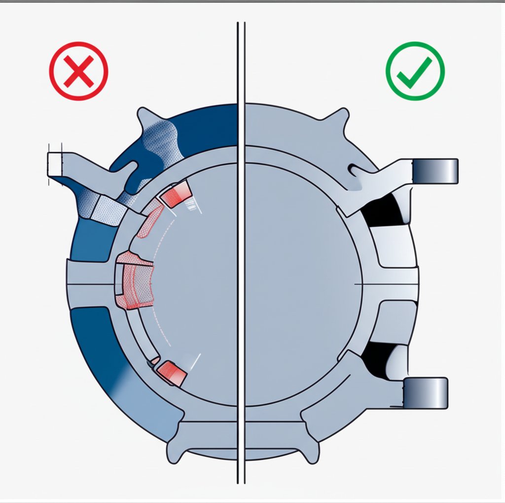
Izbočine u skladu s člankom 3. točkom (a) ovog Pravilnika, "sredstva za upravljanje" su: Umjesto bušenja rupa u debljem dijelu dijela nakon odlijevanja, šake se mogu integrirati izravno u projekt, čime se značajno uštedi vrijeme i sekundarne operacije. Da bi se pridržao načela jednake debljine zida, šefe bi trebalo izbaciti iz jezgre, što znači da imaju rupu kroz središte. To ih sprečava da postanu debele mase materijala koje bi se polako hladile i uzrokovale defekte. Također bi se trebali povezati s glavnim zidovima velikodušnim filetima i rebrima kako bi se osigurala čvrstoća i glatko protoku metala.
Kako bi se dodatno smanjila upotreba materijala i težina dijelova, dizajneri mogu strateški dodati sakovi ili šupljih profila. Ovaj proces, koji se često naziva "iskorijenjavanje", uklanja materijal iz područja koja nisu strukturno kritična. Stvaranjem ovih šupljina može se održati konstantna debljina stjenke cijelog dijela, čak i kod složenih geometrija. To ne samo da uštedi na troškovima materijala, već i skraćuje vrijeme hlađenja u kalupu, što rezultira bržim proizvodnim ciklusima. Potrebna je pažljiva analiza kako bi se osiguralo da džepovi ne kompromitiraju ukupnu čvrstoću ili funkcionalnost dijela.
| Prihvat dizajniranja | Prednosti | Odluka Komisije |
|---|---|---|
| Dizajn bez rebrića (debele stjenke) | Jednostavniji dizajn alata. | Viši troškovi materijala, dulje vremena ciklusa, povećani rizik od udubina i poroznosti. |
| Dizajn s rebrićima (tanke stjenke) | Povećana čvrstoća i krutost, manja težina, smanjeni troškovi materijala, brže hlađenje. | Zahtijeva pažljiv dizajn kako bi se izbjegli nedostaci; alat može biti nešto složeniji. |
Optimizacija za kalup i izbacivanje: ravnine razdvajanja, zakovice i igle
Uspješan lijevani dio je proizvod sinergije između geometrije dijela i mehanike kalupa. Dizajnerske odluke donesene bez uzimanja u obzir alata mogu dovesti do skupih, složenih kalupa i visoke stope grešaka. Ključni aspekti koje treba razmotriti uključuju položaj ravnine razdvajanja, upravljanje podrezima i lokaciju potisnih iglica. Promišljen dizajn u ovim područjima pojednostavljuje alat, smanjuje troškove i osigurava pouzdano vađenje dijela iz kalupa nakon ljevanja.
The linija razdvajanja je spojnica gdje se dvije polovice kalupa sastaju. Njena lokacija jedna je od prvih i najvažnijih odluka u dizajnu alata, jer utječe na gotovo svaku drugu značajku. Uvijek se preferira jednostavna, ravna ravnina razdvajanja, jer olakšava izradu alata i smanjuje troškove obrade. Složena, neplanarna ravnina razdvajanja može znatno povećati troškove izrade alata i može dovesti do problema s blatom — tankim mostom viška metala koji prodiru kroz spojnicu i koji se mora ukloniti u sekundarnoj operaciji. Dizajneri bi trebali težiti orijentaciji dijela na način koji omogućuje najizravniju moguću liniju razdvajanja.
Podrezivanja su značajke koje sprječavaju izravan izbacivanje dijela iz jednostavnog dvodijelnog kalupa. Uključuju udubljene površine ili značajke koje bi uzrokovale da se dio zaključa u kalupu. Iako su ponekad potrebne radi funkcionalnosti, treba ih izbjegavati kad god je to moguće jer zahtijevaju bočne jezgre ili klizne elemente – pokretne komponente unutar kalupa koje oblikuju značajku s podrezom i zatim se povlače prije izbacivanja. Ovi mehanizmi dodatno povećavaju troškove, složenost i potencijalne točke kvara alata. Ako je podrez neizbježan, ključno je surađivati s proizvodnim partnerom kako bi se pronašlo najučinkovitije rješenje za alat. Tvrtke s vlastitim sposobnostima dizajniranja kalupa mogu ponuditi vrijedno iskustvo u optimizaciji složenih alata za proizvodnju.
Konačno, izbacivači su čelične šipke koje istiskuju odliveni komad iz kalupa. Ove igle su ključne za uklanjanje dijela, ali neizbježno ostavljaju male kružne oznake na površini dijela. Zadatak dizajnera je odrediti površine koje nisu kritične niti estetske, gdje će ove oznake biti prihvatljive. Idealno je postaviti oznake ejection iglica na ravne i čvrste površine jer to osigurava ravnomjernu raspodjelu sile tijekom istiskivanja i smanjuje rizik od deformacije dijela. Ranom komunikacijom ovih prihvatljivih lokacija alatnici se spriječavaju estetski problemi na gotovom proizvodu.
Dizajn za lako istiskivanje – kontrolna lista
- Poјednostavite ravninu otvaranja kalupa tako da bude što ravna i pravocrtna.
- Eliminirajte podrezane oblike koliko god je moguće kako biste izbjegli potrebu za skupim bočnim jezgrama i kliznim elementima.
- Ugradite dovoljne kutove izvlačenja na svim površinama paralelnim s kretanjem kalupa.
- Označite površine koje nisu estetske, gdje su oznake ejection iglica dopuštene.
- Osigurajte da se izbacivači nalaze na ravnim, stabilnim površinama kako bi se spriječilo izobličenje tijekom izbacivanja.
Najčešća pitanja o DFM-u za ljevanje pod tlakom
1. Što uključuje dizajn pogodan za proizvodnju (DFM)?
Dizajn pogodan za proizvodnju (DFM) kod ljevanja pod tlakom obuhvaća skup principa koji imaju za cilj pojednostaviti i optimizirati dizajn dijela radi olakšavanja proizvodnje. Ključni elementi su primjena nagiba za izvlačenje, osiguravanje jednolike debljine stjenke kako bi se spriječili nedostaci, korištenje zaobljenja i polumjera kako bi se izbjegli oštri rubovi te projektiranje elemenata poput rebrića i vratova za povećanje čvrstoće uz smanjenje količine materijala. Također obuhvaća aspekte alata, poput pojednostavljenja ravnine razdvajanja i izbjegavanja zakosa.
2. Kako pristupate dizajniranju pogodnom za proizvodnju?
Pristup započinje već u ranoj fazi dizajna uz razmatranje cijelog proizvodnog procesa. Uključuje suradnju s inženjerima proizvodnje kako bi se prepoznali mogući problemi u proizvodnji. Ključni koraci uključuju pojednostavljenje dizajna, smanjenje broja dijelova, standardizaciju komponenti gdje je to moguće te pridržavanje pravila specifičnih za proces, kao što su pravila za podmazivanje kalupa (nagib, debljina zida itd.). Cilj je proaktivno riješiti probleme proizvodnje još na crtežu, gdje su izmjene jeftine, umjesto na tvorničkom podu, gdje su skuplje.
3. Što karakterizira dizajn za proizvodnju?
Dizajn za proizvodljivost karakterizira fokus na učinkovitost, smanjenje troškova i poboljšanje kvalitete putem pametnog odabira dizajna. Dizajn optimiziran za proizvodljivost obično je jednostavniji, koristi manje materijala, zahtijeva manje sekundarnih operacija i ima nižu stopu grešaka. On odražava duboko razumijevanje mogućnosti i ograničenja odabranog procesa proizvodnje, što rezultira proizvodom koji je ne samo funkcionalan, već i ekonomičan te pouzdan za masovnu proizvodnju.