 ছোট ছোট ব্যাচ, উচ্চ মান। আমাদের তাড়াতাড়ি প্রোটোটাইপিং সার্ভিস যাচাইকরণকে আরও তাড়াতাড়ি এবং সহজ করে —

এয়ারোস্পেস ধাতু ফ্যাব্রিকেশনের গোপন তথ্য: প্রমাণীকরণ নিরীক্ষকরা আসলে কী পরীক্ষা করেন
এয়ারোস্পেস ধাতু নির্মাণ সম্পর্কে বোঝা এবং এর গুরুত্বপূর্ণ ভূমিকা
কল্পনা করুন, ৩৫,০০০ ফুট উচ্চতায় একটি একক ব্র্যাকেট ব্যর্থ হচ্ছে। অথবা ২,০০০°ফারেনহাইট তাপমাত্রায় একটি টারবাইন ব্লেড ফেটে যাচ্ছে। এয়ারোস্পেস ধাতু নির্মাণে 'প্রায় ঠিক' শব্দটির কোনো স্থান নেই। এই বিশেষায়িত উৎপাদন শাখাটি কেন্দ্রীভূত হয়েছে উপাদান ও কাঠামো উৎপাদনের উপর যেখানে সবচেয়ে সূক্ষ্ম ত্রুটিও সফল ফ্লাইট এবং বিপর্যয়কর ব্যর্থতার মধ্যে পার্থক্য তৈরি করতে পারে।
অতএব এই ক্ষেত্রটি কেন এত চাপসৃষ্টিকারী? এয়ারোস্পেস ধাতু নির্মাণ ধাতু উৎপাদনের একটি বিশেষায়িত শাখা, যার মধ্যে বিমান, মহাকাশযান এবং প্রতিরক্ষা ব্যবস্থার জন্য ধাতব উপকরণগুলিকে নির্ভুলভাবে আকৃতি দেওয়া, কাটা এবং সংযোজন করা অন্তর্ভুক্ত রয়েছে। এটি বিমানের ফ্রেম থেকে শুরু করে ইঞ্জিন উপাদান, অ্যাভিওনিক্স সিস্টেম এবং অন্যান্য গুরুত্বপূর্ণ উপাদানগুলির মধ্যে সবকিছু অন্তর্ভুক্ত করে, যা যাত্রীদের নিরাপত্তা এবং মিশনের সফলতা নিশ্চিত করে।
এয়ারোস্পেস ফ্যাব্রিকেশনকে স্ট্যান্ডার্ড ম্যানুফ্যাকচারিং থেকে আলাদা করে তোলে কী?
আপনি হয়তো ভাবছেন: ধাতু ফ্যাব্রিকেশন তো ধাতু ফ্যাব্রিকেশনই—অন্য কিছু নয়? ঠিক তা নয়। একটি স্ট্যান্ডার্ড ম্যানুফ্যাকচারিং শপ সাধারণত ±০.১ মিমি টলারেন্সের মধ্যে কাজ করে, অন্যদিকে এয়ারোস্পেস ফ্যাব্রিকেশনে নিয়মিতভাবে ±০.০০২ মিমি-এর মধ্যে টলারেন্স প্রয়োজন—যা প্রায় ৫০ গুণ বেশি নির্ভুলতা নির্দেশ করে। নিচে এয়ারোস্পেস ধাতু কাজকে সাধারণ ফ্যাব্রিকেশন থেকে আলাদা করে তোলা প্রকৃত বৈশিষ্ট্যগুলো উল্লেখ করা হলো:
- চরম নির্ভুলতার প্রয়োজনীয়তা: প্রতিটি টারবাইন ব্লেড, হাইড্রোলিক ভাল্ভ এবং কাঠামোগত ব্র্যাকেটকে মাইক্রন-স্তরের নির্ভুলতা মেনে চলতে হয়, যা সাধারণ শিল্প মেশিনিংয়ের ক্ষেত্রে প্রয়োজন হয় না।
- বিশেষায়িত উপকরণ বিশেষজ্ঞতা: টাইটানিয়াম, ইনকোনেল এবং উন্নত অ্যালুমিনিয়াম ভেরিয়েন্টসহ এয়ারোস্পেস-গ্রেড অ্যালয়গুলোর কাঠামোগত বৈশিষ্ট্য বজায় রাখতে এদের জন্য বিশেষ মেশিনিং কৌশলের প্রয়োজন হয়।
- নিয়ন্ত্রক তত্ত্বাবধান: এই খাতটি কঠোর এফএএ (FAA), ইউরোপীয় এভিয়েশন সিকিউরিটি এজেন্সি (EASA) এবং আন্তর্জাতিক মানদণ্ডের অধীনে পরিচালিত হয়, যার মধ্যে তৃতীয় পক্ষের যাচাইকরণ এবং কাঁচামাল থেকে সম্পূর্ণ পণ্য পর্যন্ত সম্পূর্ণ ট্রেসেবিলিটি বাধ্যতামূলক।
- নথিপত্রের গভীরতা: প্রতিটি উপাদানের জন্য নথিভুক্ত উপাদান প্রমাণপত্র, যন্ত্রকৃত প্রক্রিয়ার লগ এবং পরিদর্শন প্রতিবেদন আবশ্যক—যা দায়িত্বপ্রাপ্তির একটি বিচ্ছিন্নহীন শৃঙ্খল গঠন করে।
ভোক্তা পণ্য বা সাধারণ শিল্প সরঞ্জামের জন্য অংশগুলি উৎপাদন করার বিপরীতে, বিমান চলাচল সংক্রান্ত উৎপাদনে প্রস্তুতকারকদের হাজার হাজার অভিন্ন অংশের জন্য প্রতিটি ক্ষেত্রে তাদের প্রক্রিয়াগুলি কার্যকর হয় কিনা তা প্রমাণ করতে হয়।
উড়ান-সম্পর্কিত গুরুত্বপূর্ণ উপাদানগুলিতে নির্ভুলতার গুরুত্বপূর্ণ ভূমিকা
বিমানের উপাদানগুলি কী ধরনের পরিস্থিতির মুখোমুখি হয় তা ভাবুন। এগুলি দ্রুত তাপমাত্রা পরিবর্তনের শিকার হয়—যেমন উড়ানের সময় শীতল অবস্থা থেকে ইঞ্জিনের কাছাকাছি চরম তাপের পরিস্থিতি পর্যন্ত। এগুলি ধ্রুব যান্ত্রিক ভার, তীব্র কম্পন এবং এমন বায়ুমণ্ডলীয় চাপ পরিবর্তন সহ্য করে যা কম মানের উপাদান ও নকশাকে ধ্বংস করে দিতে পারে।
এই পরিবেশে, নির্ভুলতা শুধুমাত্র অংশগুলি একসাথে ফিট করার বিষয় নয়—এটি বেঁচে থাকার বিষয়। নিম্নলিখিত গুরুত্বপূর্ণ বিষয়গুলি বিবেচনা করুন:
- পৃষ্ঠের গুণগত মান ক্লান্তি আয়ু নির্ধারণ করে: এয়ারোস্পেস যন্ত্রাংশের দীর্ঘস্থায়িত্ব তাদের পৃষ্ঠ অখণ্ডতার সঙ্গে ঘনিষ্ঠভাবে জড়িত। উন্নত উৎপাদন প্রক্রিয়াগুলি বার-মুক্ত কিনারা এবং অত্যন্ত মসৃণ সমাপ্তি (Ra ০.৪ µm-এর নিচে) তৈরি করে যা পীড়ন কেন্দ্রীভবন কমিয়ে দেয় এবং সূক্ষ্ম-ফাটল সৃষ্টি রোধ করে।
- মাত্রাগত নির্ভুলতা জ্বালানি দক্ষতাকে প্রভাবিত করে: ইঞ্জিন উপাদানগুলিতে এমন কি সামান্য বিচ্যুতিও জ্বালানি খরচ এবং ফ্লাইট নিরাপত্তা ক্ষুণ্ন করতে পারে।
- পুনরাবৃত্তিযোগ্যতা নির্ভরযোগ্যতা নিশ্চিত করে: একটি নির্ভুল যন্ত্রাংশ উৎপাদন করা যথেষ্ট নয়। নির্মাতাদের উচ্চ-নির্ভুলতাসম্পন্ন CMM পরীক্ষা এবং কঠোর পরিসংখ্যানভিত্তিক প্রক্রিয়া নিয়ন্ত্রণ ব্যবহার করে বৃহৎ উৎপাদন চক্র—কখনও কখনও হাজার হাজার উপাদান—জুড়ে অভিন্ন সহনশীলতা এবং সমাপ্তি বজায় রাখতে হবে।
এয়ারোস্পেস নির্মাণে, সহনশীলতাগুলি কেবল সংখ্যা নয়—এগুলি জীবনরক্ষাকারী।
এটাই কারণ শিল্প ক্ষেত্রে এত কঠোর মানদণ্ড বিকশিত হয়েছে এবং সার্টিফিকেশন অডিটররা একটি নির্মাতার প্রক্রিয়াগুলির প্রতিটি দিক পরীক্ষা করেন। যখন আপনি এমন উপাদান তৈরি করছেন যার অবশ্যই চরম পরিস্থিতিতে নিখুঁতভাবে কাজ করতে হবে, তখন নির্ভুল ধাতু নির্মাণ বাধ্যতামূলক নয়—এটি বিমান চলাচলের নিরাপত্তির মূল ভিত্তি।
বিমান চলাচল উপাদানের জন্য উপাদান নির্বাচন গাইড
আপনি কখনও ভেবেছেন কেন কিছু বিমানের অংশ প্রায় ওজনহীন হয়, অন্যদিকে কিছু অংশ ইস্পাত গলানোর মতো উচ্চ তাপমাত্রা সহ্য করতে পারে? এর উত্তর হলো উপাদান নির্বাচন—যা বিমান চলাচল নির্মাণ ও উপাদান প্রকৌশলের মধ্যে সবচেয়ে গুরুত্বপূর্ণ সিদ্ধান্তগুলির মধ্যে একটি। কোনো উপাদানের জন্য ভুল মিশ্র ধাতু নির্বাচন করা শুধু অকার্যকর নয়; এটি সমগ্র বিমানের কার্যকারিতা ও নিরাপত্তাকে ঝুঁকির মধ্যে ফেলতে পারে।
ধাতু ভিত্তিক মহাকাশ প্রযুক্তির অ্যাপ্লিকেশনগুলিতে, প্রকৌশলীদের প্রতিদ্বন্দ্বী চাহিদাগুলির মধ্যে ভারসাম্য বজায় রাখতে হয়: শক্তি বনাম ওজন, তাপ প্রতিরোধক্ষমতা বনাম যন্ত্রকরণযোগ্যতা, ক্ষয় প্রতিরোধক্ষমতা বনাম খরচ। প্রতিটি উপাদান নির্দিষ্ট অ্যাপ্লিকেশনের জন্য অনন্য সুবিধা প্রদান করে, এবং এই বিনিময়গুলি বোঝা মহাকাশ প্রযুক্তির কঠোর মানদণ্ড পূরণকারী ধাতু অংশ উৎপাদনের জন্য যেগুলি মহাকাশ প্রযুক্তির কঠোর মানদণ্ড পূরণ করে, তার জন্য অপরিহার্য।
| উপাদান প্রকার | প্রধান বৈশিষ্ট্য | তাপমাত্রার পরিসর | সাধারণ প্রয়োগ | ওজন বিবেচনা |
|---|---|---|---|---|
| অ্যালুমিনিয়াম ২০২৪ | উচ্চ শক্তি, চমৎকার ফ্যাটিগ প্রতিরোধক্ষমতা, ভালো যন্ত্রকরণযোগ্যতা | সর্বোচ্চ ১৫০°সে (৩০০°ফা) | ফিউজেলেজ কাঠামো, ওয়িং স্কিন, কাঠামোগত ফিটিং | নিম্ন ঘনত্ব (২.৭৮ গ্রাম/ঘন সেমি³); ওজন-সংবেদনশীল কাঠামোর জন্য আদর্শ |
| অ্যালুমিনিয়াম 6061 | ভালো ওয়েল্ডেবিলিটি, ক্ষয় প্রতিরোধক্ষমতা, মাঝারি শক্তি | সর্বোচ্চ ১৫০°সে (৩০০°ফা) | হাইড্রোলিক উপাদান, ব্র্যাকেট, সাধারণ কাঠামোগত অংশ | নিম্ন ঘনত্ব (২.৭০ গ্রাম/ঘন সেমি³); বহুমুখী ওজন সাশ্রয় |
| অ্যালুমিনিয়াম 7075 | সর্বোচ্চ শক্তি সম্পন্ন অ্যালুমিনিয়াম, চমৎকার পীড়ন-কর্ষণ প্রতিরোধ ক্ষমতা | সর্বোচ্চ ১২০°সে (২৫০°ফা) | উইং স্পার্স, বাল্কহেড, উচ্চ-পীড়ন ফিটিংস | নিম্ন ঘনত্ব (২.৮১ গ্রাম/ঘন সেমি³); সর্বোচ্চ শক্তি-ওজন অনুপাত |
| টাইটানিয়াম গ্রেড ৫ (Ti-6Al-4V) | শ্রেষ্ঠ শক্তি-ওজন অনুপাত, ক্ষয় প্রতিরোধ ক্ষমতা, জৈবসামঞ্জস্যতা | সর্বোচ্চ ৪০০–৫০০°সে (৭৫০–৯৩০°ফা) | ইঞ্জিন কম্প্রেসর ব্লেড, ল্যান্ডিং গিয়ার উপাদান, ফাস্টেনার | মধ্যম ঘনত্ব (৪.৪৩ গ্রাম/ঘন সেমি³); ইস্পাতের তুলনায় ৪৫% ওজন হ্রাস |
| ইনকোনেল 718 | চরম তাপমাত্রায় শক্তি, জারণ প্রতিরোধ ক্ষমতা, উচ্চ ক্লান্তি সীমা | সর্বোচ্চ ৭০০°সেলসিয়াস (১,৩০০°ফারেনহাইট) | টারবাইন ব্লেড, দহন কক্ষ, এক্সহস্ট সিস্টেম | উচ্চ ঘনত্ব (৮.১৯ গ্রাম/ঘন সেন্টিমিটার³); তাপীয় কার্যকারিতা দ্বারা ওজন বৃদ্ধির প্রভাব প্রশমিত |
| ইনকোনেল 625 | অসাধারণ ক্ষয় প্রতিরোধ ক্ষমতা, ওয়েল্ডেবিলিটি, উচ্চ ক্রিপ শক্তি | সর্বোচ্চ ৯৮০°সেলসিয়াস (১,৮০০°ফারেনহাইট) | জেট ইঞ্জিনের উপাদান, থ্রাস্ট রিভার্সার, তাপ বিনিময়কারী | উচ্চ ঘনত্ব (৮.৪৪ গ্রাম/ঘন সেন্টিমিটার³); চরম পরিবেশের জন্য নির্বাচিত |
| স্টেইনলেস স্টিল ১৭-৪ পিএইচ | উচ্চ কঠোরতা, ভালো ক্ষয় প্রতিরোধ ক্ষমতা, অবক্ষেপণ দ্বারা শক্তিকরণ | সর্বোচ্চ ৩১৫°সেলসিয়াস (৬০০°ফারেনহাইট) | ল্যান্ডিং গিয়ার পিভট ব্র্যাকেট, ফাস্টেনার, অ্যাকচুয়েটর উপাদান | উচ্চ ঘনত্ব (৭.৭৮ গ্রাম/ঘন সেমি³); যেখানে শক্তি ওজনের চিন্তা অতিক্রম করে |
| স্টেইনলেস স্টিল ১৫-৫ পিএইচ | ১৭-৪ এর তুলনায় উত্তম টাফনেস, চমৎকার অনুপ্রস্থ বৈশিষ্ট্য | সর্বোচ্চ ৩১৫°সেলসিয়াস (৬০০°ফারেনহাইট) | গঠনমূলক ফিটিং, ভাল্ভ বডি, ওয়িং-রুট আটকানোর জন্য ব্যবহৃত সংযোগ অংশ | উচ্চ ঘনত্ব (৭.৭৮ গ্রাম/ঘন সেমি³); গুরুত্বপূর্ণ লোড পাথের জন্য বজায় রাখা হয়েছে |
গঠনমূলক ও কাভারিং অ্যাপ্লিকেশনের জন্য অ্যালুমিনিয়াম মিশ্র ধাতু
যখন আপনি কোনো বিমানের বাইরের দিকে তাকাচ্ছেন—চিকন ফিউজেলেজ প্যানেল এবং ওয়িং পৃষ্ঠ—তখন আপনি প্রায় নিশ্চিতভাবেই অ্যালুমিনিয়াম মিশ্র ধাতু দেখছেন। এই উপাদানগুলি বিমান ও মহাকাশ নির্মাণে এতদিন পর্যন্ত প্রভাব বিস্তার করে আসছে, যেহেতু তারা দ্বিতীয় বিশ্বযুদ্ধের পর প্রাথমিক ও দ্বিতীয়ক গঠনমূলক উপাদান হিসেবে স্টিলের পরিবর্তে ব্যবহৃত হয়েছিল .
অ্যালুমিনিয়াম কেন? বিশুদ্ধ অ্যালুমিনিয়াম আসলে বেশ দুর্বল ও নমনীয়—এটি কোনো বিমান নির্মাণের উপযুক্ত উপাদান নয়। কিন্তু যখন এটি তামা, ম্যাগনেসিয়াম, ম্যাঙ্গানিজ, সিলিকন, দস্তা ও লিথিয়ামের মতো মৌলগুলির সাথে মিশ্রিত হয়, তখন এর যান্ত্রিক বৈশিষ্ট্যগুলি ব্যাপকভাবে পরিবর্তিত হয়, যদিও এটি সেই গুরুত্বপূর্ণ নিম্ন আপেক্ষিক ওজন বজায় রাখে।
এখানে বিমান চলাচলের ক্ষেত্রে প্রধান অ্যালুমিনিয়াম সিরিজগুলির বিভাজন দেওয়া হল:
- ২০০০ সিরিজ (Al-Cu): বিমানের কাঠামোর কাজের ঘোড়া। অ্যালুমিনিয়াম ২০২৪ অসাধারণ ক্লান্তি প্রতিরোধ ক্ষমতা প্রদান করে, যা বিমানের সেবা জীবনকালে কোটি কোটি চাপ চক্রের মুখোমুখি হওয়ার পরিস্থিতিতে ফিউজেলেজ স্কিন এবং ওয়িং কাঠামোর জন্য আদর্শ।
- ৬০০০ সিরিজ (Al-Mg-Si): অ্যালুমিনিয়াম ৬০৬১ এর ওয়েল্ডেবিলিটি এবং করোশন প্রতিরোধ ক্ষমতার জন্য এটি বিশেষভাবে উল্লেখযোগ্য। আপনি এটিকে হাইড্রোলিক সিস্টেমের উপাদান, ব্র্যাকেট এবং যেসব অ্যাপ্লিকেশনে যোগ করার নমনীয়তা গুরুত্বপূর্ণ, সেখানে পাবেন।
- ৭০০০ সিরিজ (Al-Zn-Mg): যখন সর্বোচ্চ শক্তির প্রয়োজন হয়, তখন অ্যালুমিনিয়াম ৭০৭৫ সেই প্রয়োজন পূরণ করে। ওয়িং স্পার, বাল্কহেড এবং উচ্চ-চাপ ফিটিংগুলি এই মিশ্র ধাতুর উৎকৃষ্ট যান্ত্রিক বৈশিষ্ট্যের উপর নির্ভরশীল।
- ৮০০০ সিরিজ (Al-Li): সর্বশেষ প্রজন্ম। অ্যালুমিনিয়াম-লিথিয়াম মিশ্র ধাতুগুলি পরবর্তী প্রজন্মের বিমান ডিজাইনের জন্য কাঠামোগত অখণ্ডতা বজায় রেখে ওজন সাশ্রয়কে আরও এগিয়ে নিয়ে যায়।
অ্যালুমিনিয়াম মিশ্র ধাতুগুলির সাথে বাণিজ্যিক আদান-প্রদান কী? একটি বৈশিষ্ট্য উন্নত হলে, অন্যান্য বৈশিষ্ট্যগুলি প্রায়শই ক্ষতিগ্রস্ত হয়। উচ্চ-শক্তি সম্পন্ন ৭০৭৫ মিশ্র ধাতুর ক্ষয় প্রতিরোধ ক্ষমতা ৬০৬১-এর তুলনায় কম। অত্যন্ত যন্ত্রযোগ্য মিশ্র ধাতুগুলি কখনও কখনও কিছুটা ফ্যাটিগ পারফরম্যান্স হারায়। প্রতিটি উপাদানের অবস্থানের জন্য অপ্টিমাল ভারসাম্য খুঁজে পেতে গভীর ধাতুবিদ্যা বিশেষজ্ঞতা প্রয়োজন।
যখন টাইটানিয়াম এবং সুপারঅ্যালয় অপরিহার্য হয়ে ওঠে
এখন পর্যন্ত এটা সরাসরি মনে হচ্ছে? এখানেই এটা আকর্ষক হয়ে ওঠে। কিছু বিমান উপাদান এমন পরিস্থিতির মুখোমুখি হয় যা সর্বোত্তম অ্যালুমিনিয়াম মিশ্র ধাতুগুলিকেও ধ্বংস করে দিতে পারে। ইঞ্জিন অংশগুলি নিয়মিতভাবে ৫০০°সেলসিয়াসের বেশি তাপমাত্রা অতিক্রম করে। ল্যান্ডিং গিয়ার অ্যাসেম্বলিগুলি চরম আঘাত লোড সহ্য করতে হয়। এই অ্যাপ্লিকেশনগুলির জন্য টাইটানিয়াম এবং নিকেল-ভিত্তিক সুপারঅ্যালয় প্রয়োজন।
টাইটানিয়াম সংকর বিমান চলাচল শিল্পে উপকরণ নির্বাচনে টাইটানিয়াম একটি অনন্য মধ্যবর্তী অবস্থান দখল করে। এগুলির উচ্চ নির্দিষ্ট বৈশিষ্ট্য রয়েছে যার মধ্যে ভালো ফ্যাটিগ শক্তি/টেনসাইল শক্তির অনুপাত এবং ৪০০-৫০০°সেলসিয়াস পর্যন্ত তাপমাত্রায় উল্লেখযোগ্য শক্তি ধরে রাখার ক্ষমতা অন্তর্ভুক্ত। এদের চমৎকার ক্ষয় প্রতিরোধ ক্ষমতা এদেরকে বিভিন্ন বায়ুমণ্ডলীয় পরিস্থিতির সম্মুখীন হওয়া উপাদানগুলির জন্য আদর্শ করে তোলে।
যাইহোক, টাইটানিয়ামের সাথে কিছু গুরুতর সতর্কতা জড়িত:
- খরচ প্রিমিয়ামঃ টাইটানিয়ামের দাম অ্যালুমিনিয়াম বা ইস্পাতের তুলনায় প্রায় সাতগুণ বেশি, যার মধ্যে কাঁচামাল এবং উত্পাদন ব্যয় উভয়ই অন্তর্ভুক্ত।
- ঘনত্বের শাস্তিঃ স্টিলের চেয়ে হালকা হলেও, টাইটানিয়াম এর ঘনত্ব (৪.৪৩ গ্রাম/সেমি 3) অ্যালুমিনিয়ামের চেয়ে বেশি, ব্যাপকভাবে ব্যবহারের সময় ওজন জরিমানা আরোপ করে।
- পরিবেশগত সংবেদনশীলতা: লবণাক্ত পরিবেশে তাপমাত্রা এবং চাপের সংস্পর্শে থাকা বিশেষত বিমানবাহী বিমানের জন্য সমস্যাযুক্তবিশেষত বৈশিষ্ট্যগুলিকে নেতিবাচকভাবে প্রভাবিত করতে পারে।
ইনকোনেলের মতো নিকেল ভিত্তিক সুপারলেগ যখন তাপমাত্রা টাইটানিয়ামের সক্ষমতা অতিক্রম করে তখন ছবিতে প্রবেশ করে। ইনকনেল ৭১৮ ৬৫০°সি এ ৮০০ এমপিএ বা তার বেশি শক্ত এবং ৫ম শ্রেণীর টাইটানিয়ামের চেয়ে ৫৫% বেশি শক্তি দেয়। জেট ইঞ্জিনের সবচেয়ে গরম অংশে ঘুরতে থাকা টারবাইন ব্লেডের জন্য, অন্য কিছুই কাজ করবে না।
৫৫০ ডিগ্রি সেলসিয়াসের উপরে, ইনকোনেল কোন পছন্দ নয়, এটা একটি প্রয়োজনীয়তা।
উপকরণ নির্বাচনের সিদ্ধান্তটি শেষ পর্যন্ত উপাদানের অবস্থান এবং কার্যকরী অবস্থার উপর নির্ভর করে। যেসব ফিউজেলেজ প্যানেল কখনও চরম তাপমাত্রার সম্মুখীন হয় না, সেগুলোতে অ্যালুমিনিয়ামের ওজন হ্রাসের সুবিধা পাওয়া যায়। ইঞ্জিনের উত্তপ্ত অংশগুলোর জন্য ইনকোনেলের তাপীয় স্থিতিশীলতা আবশ্যক। ল্যান্ডিং গিয়ারের উপাদানগুলো—যা উচ্চ আঘাত লোডের সম্মুখীন হয় কিন্তু মধ্যম তাপমাত্রায় কাজ করে—প্রায়শই শক্তি, টানাটানি এবং ক্ষয় প্রতিরোধের সংমিশ্রণের জন্য টাইটানিয়াম বা উচ্চ-শক্তি স্টেইনলেস স্টিলের বিভিন্ন রূপ ব্যবহার করে।
এই উপাদান-প্রয়োগ সম্পর্কগুলো বোঝা এয়ারোস্পেস ফ্যাব্রিকেশনের জন্য মৌলিক। কিন্তু সঠিক মিশ্র ধাতু নির্বাচন করা হলেও শুধুমাত্র সমীকরণের অর্ধেক অংশই সমাধান করা হয়—এই উপাদানগুলোকে আকৃতি দেওয়ার জন্য যে ফ্যাব্রিকেশন পদ্ধতিগুলো ব্যবহার করা হয়, সেগুলোও ততটাই গুরুত্বপূর্ণ।
এয়ারোস্পেস অ্যাপ্লিকেশনের জন্য তুলনামূলক ফ্যাব্রিকেশন পদ্ধতিসমূহ
আপনি আপনার কম্পোনেন্টের জন্য সঠিক এয়ারোস্পেস-গ্রেড অ্যালয় নির্বাচন করেছেন। এখন একটি সমানভাবে গুরুত্বপূর্ণ প্রশ্ন আসছে: আপনি এটিকে কীভাবে আকৃতি দেবেন? আপনি যে ফ্যাব্রিকেশন পদ্ধতি নির্বাচন করেন, তা সরাসরি মাত্রিক নির্ভুলতা, পৃষ্ঠের সমাপ্তি, উৎপাদন গতি এবং শেষ পর্যন্ত আপনার পার্টটি সার্টিফিকেশন অডিট পাস করবে কিনা—এই সবকিছুর উপর প্রভাব ফেলে।
প্রতিটি উৎপাদন পদ্ধতি নিজস্ব বিশিষ্ট সুবিধা নিয়ে আসে এয়ারোস্পেস শীট মেটাল ফ্যাব্রিকেশন এর ক্ষেত্রে। কিছু পদ্ধতি সরল ব্র্যাকেটগুলির উচ্চ-পরিমাণ উৎপাদনে উৎকৃষ্ট। অন্যগুলি জটিল ইঞ্জিন হাউজিং পরিচালনা করে যার অভ্যন্তরীণ জ্যামিতি অত্যন্ত জটিল। প্রতিটি পদ্ধতি কখন এবং কেন প্রয়োগ করা উচিত—এই বুঝতে পারা সফল এয়ারোস্পেস নির্মাতাদের সেইসব নির্মাতাদের থেকে পৃথক করে যারা গুণগত প্রত্যাখ্যান এবং খরচ অতিক্রমের সমস্যায় ভুগছে।
| পদ্ধতি | সেরা উপকরণ | সহনশীলতা ক্ষমতা | আদর্শ কম্পোনেন্ট প্রকার | সীমাবদ্ধতা |
|---|---|---|---|---|
| CNC মেশিনিং | অ্যালুমিনিয়াম, টাইটানিয়াম, স্টেইনলেস স্টিল, ইনকোনেল, কম্পোজিট | ±0.001" (0.025 মিমি) মানক; ±0.0001" (0.0025 মিমি) অর্জনযোগ্য | ইঞ্জিন হাউজিং, কাঠামোগত ব্র্যাকেট, জটিল 3D জ্যামিতি, প্রোটোটাইপ | উচ্চতর উপকরণ বর্জ্য; উচ্চ-পরিমাণ উৎপাদনের জন্য ধীরগতি; কঠিন অ্যালয়গুলিতে টুল ক্ষয় |
| লেজার কাটিং | পাতলা অ্যালুমিনিয়াম, ইস্পাত, স্টেইনলেস স্টিল (প্রায় ~২৫ মিমি পর্যন্ত পুরুত্ব) | পাতলা উপকরণের জন্য সাধারণত ±০.০০৫" (০.১২৭ মিমি) | জটিল প্যানেল কাটআউট, বিস্তারিত ব্র্যাকেট, পাতলা-দেয়াল বিশিষ্ট আবদ্ধ করার বক্স | তাপ-প্রভাবিত অঞ্চল; সীমিত পুরুত্ব ক্ষমতা; প্রতিফলক ধাতুর জন্য উপযুক্ত নয় |
| মেটাল স্ট্যাম্পিং | অ্যালুমিনিয়াম, ইস্পাত, তামা মিশ্র ধাতু, পাতলা শীট ধাতু | ডাইয়ের নির্ভুলতার উপর নির্ভর করে ±০.০০৫" থেকে ±০.০১৫" (০.১২৭–০.৩৮১ মিমি) | উচ্চ পরিমাণে উৎপাদিত ব্র্যাকেট, ক্লিপ, মাউন্টিং প্লেট, শিল্ডিং উপাদান | শুরুতে টুলিংয়ের উচ্চ খরচ; পাতলা উপকরণের জন্য সীমিত; ডিজাইন পরিবর্তনের জন্য নতুন ডাই প্রয়োজন |
| জলজেট কাটিং | টাইটানিয়াম, কঠিনীভূত ইস্পাত, কম্পোজিট, সিরামিকসহ সমস্ত ধাতু | ±০.০০৩" থেকে ±০.০০৫" (০.০৭৬–০.১২৭ মিমি) | ঘন প্লেট কাটিং, তাপ-সংবেদনশীল অ্যালয়, কম্পোজিট ল্যামিনেট | ধীর কাটিং গতি; উচ্চতর অপারেটিং খরচ; ঘন উপকরণে কিনারা সংকুচিত হওয়া |
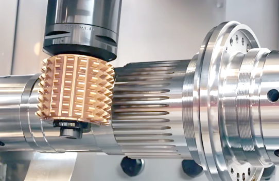
| ইডিএম (ইলেকট্রিক্যাল ডিসচার্জ মেশিনিং) | শুধুমাত্র পরিবাহী ধাতু: কঠিনীভূত ইস্পাত, টাইটানিয়াম, ইনকোনেল, টাংস্টেন | ±০.০০০২" থেকে ±০.০০০৫" (০.০০৫–০.০১৩ মিমি) | টারবাইন ব্লেড স্লট, নির্ভুল ডাই উপাদান, মাইক্রো-বৈশিষ্ট্য, কঠিনীভূত টুলিং | অত্যন্ত ধীর প্রক্রিয়া; শুধুমাত্র পরিবাহী উপকরণ; প্রতিটি অংশের জন্য উচ্চতর খরচ |
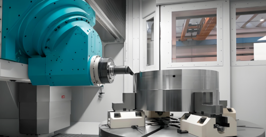
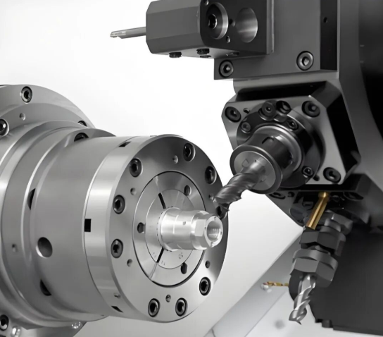
জটিল গঠনমূলক উপাদানের জন্য সিএনসি মেশিনিং
যখন এয়ারোস্পেস ইঞ্জিনিয়াররা জটিল জ্যামিতি এবং কঠোর সহনশীলতা সহ অংশগুলি তৈরি করতে চান, তখন সিএনসি মেশিনিং এখনও সোনার মানদণ্ড বলে বিবেচিত হয়। এই কম্পিউটার-নিয়ন্ত্রিত প্রক্রিয়াটি সহনশীলতা অর্জন করতে পারে ±০.০০১" (০.০২৫ মিমি) বা তার চেয়ে ভালো —এবং কিছু উন্নত মেশিন অত্যন্ত গুরুত্বপূর্ণ উপাদানের জন্য ±০.০০০১" (০.০০২৫ মিমি) পর্যন্ত সহনশীলতা অর্জন করতে পারে।
কোন কারণে এয়ারোস্পেস অ্যাপ্লিকেশনের জন্য সিএনসি মেশিনিং বিশেষভাবে মূল্যবান? এই সুবিধাগুলি বিবেচনা করুন:
- অনুপম নির্ভুলতা: সিএনসি মেশিনগুলি এমন অংশ তৈরি করতে পারে যার টলারেন্স অত্যন্ত কঠোর এবং জটিল বিবরণ রয়েছে, যা ঐতিহ্যগত পদ্ধতিতে তৈরি করা কঠিন বা অসম্ভব হতে পারে।
- উপাদানের বহুমুখিতা: আপনি যদি অ্যালুমিনিয়াম, টাইটানিয়াম, স্টেইনলেস স্টিল বা ইনকোনেল-এর মতো চাহিদাপূর্ণ সুপারঅ্যালয়ের সাথে কাজ করছেন, তবে সিএনসি মেশিনিং উপাদানের বৈশিষ্ট্যগুলির সাথে সামঞ্জস্য বজায় রাখে।
- জটিল জ্যামিতির ক্ষমতা: বহু-অক্ষ সিএনসি মেশিনগুলি আধুনিক ইঞ্জিন হাউজিং এবং গঠনমূলক ফিটিংগুলিকে সংজ্ঞায়িত করে এমন বক্র পৃষ্ঠ, অভ্যন্তরীণ চ্যানেল এবং যৌগিক কোণগুলি তৈরি করে।
- পুনরাবৃত্তি সাধনযোগ্যতা: একবার প্রোগ্রাম করা হলে, সিএনসি মেশিনগুলি উৎপাদন চক্রের মধ্যে অভিন্ন অংশগুলি তৈরি করে—যা প্রতিটি উপাদানকে অভিন্ন স্পেসিফিকেশন পূরণ করতে হবে এমন পরিস্থিতিতে অপরিহার্য।
- হালকা অপ্টিমাইজেশন: নির্ভুল কাটিং প্রতিটি অংশের জন্য প্রয়োজনীয় উপাদানের পরিমাণ কমিয়ে দেয়, যা সরাসরি বিমানের ওজন হ্রাসে অবদান রাখে।
বাণিজ্যিক সমঝোতা? সিএনসি মেশিনিংয়ে কঠিন ব্লকগুলি থেকে উপাদান কেটে ফেলা হয়, যা উল্লেখযোগ্য পরিমাণ বর্জ্য তৈরি করতে পারে—বিশেষ করে দামি টাইটানিয়াম বা ইনকোনেল বিলেটগুলির ক্ষেত্রে। উচ্চ-পরিমাণের সরল অংশগুলির জন্য স্ট্যাম্পিংয়ের তুলনায় উৎপাদন গতি ধীর হয়। তবে জটিল ইঞ্জিন উপাদান, প্রোটোটাইপ বিকাশ এবং কম-থেকে-মধ্যম পরিমাণের গাঠনিক অংশগুলির জন্য সিএনসি মেশিনিংয়ের নির্ভুলতা ও নমনীয়তা এটিকে অপ্রতিস্থাপ্য করে তোলে।
এয়ারোস্পেস প্রোটোটাইপিংয়ের জন্য সিএনসি মেশিনিং পছন্দনীয় পদ্ধতি, কারণ এটি উচ্চ নির্ভুলতা, পুনরাবৃত্তিযোগ্যতা, ন্যূনতম সেটআপ সময় এবং সরল থেকে জটিল উপাদান উৎপাদনের জন্য বহুমুখীতা প্রদান করে।
বিমানের কাঠামোর বাইরের আবরণের জন্য শীট মেটাল ফর্মিং প্রযুক্তি
এখন কল্পনা করুন, আপনার একটি বাণিজ্যিক বিমান প্রোগ্রামের জন্য ৫০,০০০টি অভিন্ন মাউন্টিং ব্র্যাকেট প্রয়োজন। প্রতিটি ব্র্যাকেট সিএনসি মেশিনের মাধ্যমে তৈরি করতে মাস ধরে সময় লাগবে এবং এটি অত্যন্ত ব্যয়বহুল হবে। এখানেই এয়ারোস্পেস মেটাল স্ট্যাম্পিং এবং এয়ারোস্পেস মেটাল ফর্মিং ও বেন্ডিং প্রযুক্তিগুলি তাদের মূল্য প্রমাণ করে।
মেটাল স্ট্যাম্পিং এটি কাটিং, পাঞ্চিং এবং ফর্মিং অপারেশনের মাধ্যমে শীট মেটালকে আকৃতি দেওয়ার জন্য ডাই এবং প্রেস ব্যবহার করে। একবার ডাইগুলো তৈরি হয়ে গেলে, উৎপাদন অত্যন্ত দক্ষ হয়ে ওঠে—উচ্চ-পরিমাণ উৎপাদন লাইনে ন্যূনতম শ্রম হস্তক্ষেপে অবিরামভাবে পার্টস উৎপাদন করা সম্ভব হয়। ফলাফল কী? ব্র্যাকেট, ক্লিপ, মাউন্টিং প্লেট এবং শিল্ডিং কম্পোনেন্টসহ প্রতিটি বিমানের প্রয়োজনীয় পার্টসের প্রতি-ইউনিট খরচ উল্লেখযোগ্যভাবে কমে যায়।
তবে, স্ট্যাম্পিংয়ের ক্ষেত্রে সাবধানতাপূর্ণ বিবেচনা প্রয়োজন:
- প্রাথমিক টুলিং বিনিয়োগ: নির্ভুল ডাই তৈরি করতে উল্লেখযোগ্য প্রাথমিক ব্যয় প্রয়োজন, যার ফলে স্ট্যাম্পিং শুধুমাত্র বড় উৎপাদন পরিমাণের জন্য অর্থনৈতিকভাবে সমীচীন হয়।
- উপাদানের সীমাবদ্ধতা: স্ট্যাম্পিং সাধারণত পাতলা ধাতুর সাথে সবচেয়ে ভালোভাবে কাজ করে—অটোমোটিভ ও এয়ারোস্পেস অ্যাপ্লিকেশনে সাধারণত যেসব ধাতু ব্যবহৃত হয়, যেমন অ্যালুমিনিয়াম, স্টিল এবং তামা অ্যালয়।
- ডিজাইনের দৃঢ়তা: একবার ডাইগুলো উৎপাদিত হয়ে গেলে, ডিজাইন পরিবর্তনের জন্য নতুন টুলিং প্রয়োজন হয়। এটি স্ট্যাম্পিংকে বিকাশ পর্যায়ে কম উপযুক্ত করে তোলে, যখন স্পেসিফিকেশনগুলো পরিবর্তনশীল হতে পারে।
কাটিং অপারেশনের জন্য, লেজার কাটিং পাতলা উপকরণ থেকে জটিল প্যানেল কাটআউট এবং বিস্তারিত ব্র্যাকেট তৈরি করতে এটি অত্যন্ত দক্ষ। ফোকাসড বীমটি ন্যূনতম উপকরণ অপচয়ের সাথে সঠিক কিনারা তৈরি করে। তবে, লেজার কাটিং তাপ-প্রভাবিত অঞ্চল তৈরি করে যা উপকরণের বৈশিষ্ট্যগুলিকে পরিবর্তন করতে পারে—যা ফ্লাইট-সমালোচনামূলক উপাদানগুলির জন্য একটি উদ্বেগের বিষয়।
জলজেট কাটিং এই তাপ সমস্যার সমাধান সম্পূর্ণরূপে করে। এই শীতল-কাটিং প্রক্রিয়ায় উচ্চ চাপের জলের সাথে অ্যাব্রেসিভ কণা মিশ্রিত করে প্রায় যেকোনো উপকরণ—যেমন তাপ-সংবেদনশীল টাইটানিয়াম মিশ্র ধাতু এবং যৌগিক ল্যামিনেট—কে কেটে ফেলা হয়, যা তাপীয় কাটিং পদ্ধতির দ্বারা ক্ষতিগ্রস্ত হতে পারে। জলজেট কাটিং উপকরণের বৈশিষ্ট্যগুলি অক্ষুণ্ণ রেখে শীতল কাটিং প্রক্রিয়ার সাথে বহুমুখিতা প্রদান করে।
অবশেষে, ইডিএম (ইলেকট্রিক্যাল ডিসচার্জ মেশিনিং) এটি একটি বিশেষায়িত নিচে অবস্থান করে। যখন আপনার অত্যন্ত কঠিন উপকরণগুলি মেশিন করা প্রয়োজন হয় অথবা ইঞ্চির দশ হাজার ভাগের এক ভাগ পর্যন্ত সহনশীলতা সহ মাইক্রো-বৈশিষ্ট্য তৈরি করা হয়, তখন ইডিএম (EDM) সেই কাজটি সম্পন্ন করে। টারবাইন ব্লেডের শীতলীকরণ স্লট, নির্ভুল ডাই উপাদান এবং কঠিন সুপারঅ্যালয়ের জটিল বৈশিষ্ট্যগুলি প্রায়শই এই ধীরগতির কিন্তু অসাধারণভাবে নির্ভুল পদ্ধতির প্রয়োজন হয়।
মূল ধারণাটি কী? কোনও একক নির্মাণ পদ্ধতি প্রতিটি এয়ারোস্পেস অ্যাপ্লিকেশনের জন্য উপযুক্ত নয়। অভিজ্ঞ নির্মাতারা উপাদানের প্রয়োজনীয়তা অনুযায়ী পদ্ধতিগুলি মিলিয়ে নেন—উচ্চ পরিমাণের ব্র্যাকেটের জন্য স্ট্যাম্পিং, জটিল গঠনমূলক অংশের জন্য সিএনসি মেশিনিং, তাপ-সংবেদনশীল অ্যালয়ের জন্য ওয়াটারজেট এবং অতি-নির্ভুল বৈশিষ্ট্যের জন্য ইডিএম (EDM) ব্যবহার করেন। এই কৌশলগত পদ্ধতি খরচ, গুণগত মান এবং উৎপাদন গতির মধ্যে ভারসাম্য বজায় রাখে এবং প্রতিটি উপাদান প্রমাণীকরণের প্রয়োজনীয়তা পূরণ করে তা নিশ্চিত করে।
উপকরণ নির্বাচন করা হয়ে গেছে এবং নির্মাণ পদ্ধতিগুলি বোঝা গেছে; পরবর্তী গুরুত্বপূর্ণ স্তরটি হল এয়ারোস্পেস নির্মাণের প্রতিটি দিককে নিয়ন্ত্রণ করা প্রমাণীকরণ ব্যবস্থা।
এয়ারোস্পেস শিল্পের সার্টিফিকেশন ও অনুপালন প্রয়োজনীয়তা নেভিগেট করা
সুতরাং আপনি উপকরণ নির্বাচন এবং নির্মাণ পদ্ধতিতে দক্ষতা অর্জন করেছেন। কিন্তু এখানে বাস্তবতা হলো: যদি আপনি প্রমাণ করতে না পারেন যে আপনার প্রক্রিয়াগুলো এয়ারোস্পেস শিল্পের মানদণ্ড পূরণ করে, তবে এসব কিছুই গুরুত্বপূর্ণ নয়। সার্টিফিকেশন ইকোসিস্টেম-এ আপনাকে স্বাগতম—এটি একটি জটিল ক্রেডেনশিয়ালের জাল, যা যোগ্য এয়ারোস্পেস ধাতু নির্মাণ সেবা থেকে এমন নির্মাতাদের পৃথক করে যারা শুধুমাত্র দাবি করে যে তারা কাজটি করতে পারে।
এয়ারোস্পেস OEM-গুলো কেন তাদের সরবরাহকারীদের কাছ থেকে একাধিক সার্টিফিকেশন চায়? কারণ প্রতিটি সার্টিফিকেশন গুণগত মান, নিরাপত্তা এবং প্রক্রিয়া নিয়ন্ত্রণের বিভিন্ন দিককে কভার করে। এটিকে স্তরযুক্ত সুরক্ষা হিসেবে ভাবুন—ISO 9001 আপনার গুণগত ব্যবস্থাপনা ভিত্তি প্রতিষ্ঠা করে, AS9100D বিমান শিল্প-বিশেষ প্রয়োজনীয়তা যোগ করে, NADCAP আপনার বিশেষ প্রক্রিয়াগুলোর বৈধতা যাচাই করে, এবং AWS D17.1 আপনার ওয়েল্ডিং দক্ষতা সার্টিফাই করে। একত্রে, এগুলো একটি সম্পূর্ণ তত্ত্বাবধান তৈরি করে যা সরবরাহ শৃঙ্খলের প্রতিটি স্তরে অডিটররা যাচাই করেন।
AS9100D কীভাবে বিমান শিল্পের জন্য ISO 9001-এর উপর ভিত্তি করে গড়ে ওঠে
যদি আপনি ISO 9001:2015 সম্পর্কে পরিচিত হন, তবে আপনি ইতিমধ্যেই এয়ারোস্পেস গুণগত ব্যবস্থাপনার ভিত্তি বুঝতে পারছেন। কিন্তু এখানে অনেক উৎপাদনকারী যা মিস করেন: AS9100 এর প্রয়োজনীয়তাগুলির জন্য ISO 9001 মানকে ভিত্তি হিসেবে ব্যবহার করে এবং বিমান চলাচল, মহাকাশ ও প্রতিরক্ষা ক্ষেত্রের সাথে সম্পর্কিত কিছু অতিরিক্ত প্রয়োজনীয়তা ও টীকা সমগ্র মানক জুড়ে যোগ করে। শিল্প .
উভয় মানকই Annex L-এর উপর ভিত্তি করে একই উচ্চ-স্তরের গঠন ভাগ করে নেয়, যা সমস্ত ISO ব্যবস্থাপনা ব্যবস্থার জন্য একটি সাধারণ কাঠামো তৈরি করে। এছাড়া, উভয় মানকই সমস্ত প্রক্রিয়ায় প্রযোজ্য পরিকল্পনা-কর-পরীক্ষা-কার্যকর (PDCA) চক্র ব্যবহার করে। এই সামঞ্জস্যতা ISO 9001 থেকে AS9100-এ রূপান্তরিত হওয়াকে তুলনামূলকভাবে সরাসরি করে—যদি আপনি অতিরিক্ত প্রয়োজনীয়তাগুলি কোথায় প্রযোজ্য তা বুঝতে পারেন।
AS9100D আসলে কী যোগ করে? বিমান চলাচল-বিশেষ প্রয়োজনীয়তাগুলি মানক জুড়ে ইটালিক ফন্টে উপস্থিত হয় এবং এগুলি নিম্নলিখিত গুরুত্বপূর্ণ ক্ষেত্রগুলিতে ফোকাস করে:
- পণ্য বাস্তবায়নের জন্য পরিকল্পনা: প্রকল্প ব্যবস্থাপনা, ঝুঁকি ব্যবস্থাপনা, পণ্যের কনফিগারেশন ব্যবস্থাপনা এবং কাজের স্থানান্তর নিয়ন্ত্রণের জন্য অতিরিক্ত প্রয়োজনীয়তা। ঝুঁকি চিহ্নিতকরণ ও মূল্যায়ন সমগ্র মানদণ্ড জুড়ে পরিচালিত হয়, কারণ বিমান শিল্পের জন্য ঝুঁকি ব্যবস্থাপনা একেবারেই অপরিহার্য।
- ক্রয় ও ক্রয়কৃত পণ্য: সরবরাহকারী নিয়ন্ত্রণ সংক্রান্ত ব্যাপক অতিরিক্ত প্রয়োজনীয়তা—যা সাধারণ ISO 9001 সরবরাহকারী ব্যবস্থাপনার তুলনায় অনেক কঠোর।
- উৎপাদন ও সেবা প্রদান: এই অংশে সবচেয়ে উল্লেখযোগ্য পরিবর্তনগুলি অন্তর্ভুক্ত। উৎপাদন প্রক্রিয়া, উৎপাদন সরঞ্জামের উপর প্রয়োজনীয় নিয়ন্ত্রণ এবং ডেলিভারির পরে সমর্থন—সবগুলোই বিমান শিল্পের বিশেষ প্রয়োজনীয়তা অনুযায়ী উচ্চতর পরীক্ষা-নিরীক্ষার মধ্যে আসে।
- অ-অনুরূপ প্রক্রিয়া: AS9100D অ-অনুরূপতা পরিচালনা, প্রক্রিয়া ও পণ্যের উপর ব্যবস্থা গ্রহণ এবং সমস্যা দেখা দিলে সংশোধনমূলক ব্যবস্থা বাস্তবায়ন সংক্রান্ত আরও বিস্তারিত প্রয়োজনীয়তা নির্দিষ্ট করে।
মূল কথা হল? ISO 9001 সার্টিফিকেশন আপনার সংস্থার একটি গুণগত ব্যবস্থাপনা ব্যবস্থা রয়েছে তা প্রদর্শন করে। AS9100D সার্টিফিকেশন প্রমাণ করে যে এই ব্যবস্থা এয়ারোস্পেস উৎপাদনের উচ্চতর প্রয়োজনীয়তা পূরণ করে—যেখানে একটি অ-অনুরূপ অংশ সমগ্র বিমানবহুলকে ভূমিতে আটকে দিতে পারে।
NADCAP বিশেষ প্রক্রিয়া অ্যাক্রেডিটেশন ব্যাখ্যা
AS9100D সার্টিফিকেশন থাকা সত্ত্বেও, আপনার কাজ শেষ হয়নি। কিছু উৎপাদন প্রক্রিয়া—যাদেরকে "বিশেষ প্রক্রিয়া" বলা হয়—অতিরিক্ত তৃতীয় পক্ষের যাচাইয়ের প্রয়োজন হয়। এখানেই NADCAP কাজে আসে।
Nadcap স্বীকৃতি এটি একটি বৈশ্বিক উৎকৃষ্টতার চিহ্ন যা সমালোচনামূলক প্রক্রিয়া ও পণ্যের জন্য এয়ারোস্পেস শিল্পের কঠোর প্রয়োজনীয়তা পূরণের সাক্ষ্য দেয়। পারফরম্যান্স রিভিউ ইনস্টিটিউট (PRI) দ্বারা পরিচালিত এই অ্যাক্রেডিটেশনটি বিশ্বের অগ্রণী এয়ারোস্পেস, প্রতিরক্ষা ও মহাকাশ কোম্পানিগুলো দ্বারা স্বীকৃত এবং আবশ্যক।
NADCAP অন্যান্য সার্টিফিকেশন থেকে কীভাবে আলাদা? এটি শিল্প-পরিচালিত, অর্থাৎ এয়ারোস্পেস OEMগুলি নিজেরাই নিরীক্ষণ মানদণ্ড এবং তদারকি নির্দেশিকা প্রতিষ্ঠার জন্য সহযোগিতা করে। এটি নিশ্চিত করে যে অ্যাক্রেডিটেশন প্রোগ্রামটি সাধারণ গুণগত নীতির পরিবর্তে প্রকৃত উৎপাদন প্রয়োজনীয়তার প্রতি সরাসরি সাড়া দেয়।
NADCAP এর আওতায় ২৬টি সমালোচনামূলক প্রক্রিয়া অ্যাক্রেডিটেশন রয়েছে, যার মধ্যে রয়েছে:
- তাপ চিকিত্সাঃ এটি তাপীয় প্রক্রিয়াকরণ যে নির্দিষ্ট উপাদান বৈশিষ্ট্যের প্রয়োজনীয়তা পূরণ করে তা যাচাই করে
- রসায়ন প্রক্রিয়াকরণ: পৃষ্ঠ চিকিত্সা, প্লেটিং এবং রাসায়নিক রূপান্তর কোটিং কভার করে
- অ-নাশক পরীক্ষা (NDT): এক্স-রে, অলট্রাসাউন্ড এবং ডাই পেনিট্রেন্ট পরীক্ষণের মতো পরীক্ষা পদ্ধতিগুলি সঠিকভাবে সম্পাদন করা হয়েছে কিনা তা নিশ্চিত করে
- ঢালাইঃ ফিউশন ওয়েল্ডিং প্রক্রিয়াগুলি যে এয়ারোস্পেস স্পেসিফিকেশন পূরণ করে তা সার্টিফাই করে
- আবরণ: সুরক্ষামূলক এবং কার্যকরী কোটিং প্রয়োগগুলি যাচাই করে
- উপাদান পরীক্ষণ প্রযুক্তিগার: যে পরীক্ষণ সুবিধাগুলি উপাদান বৈশিষ্ট্য যাচাই করে তাদের অ্যাক্রেডিট করে
- অ্যাডিটিভ ম্যানুফ্যাকচারিং: এয়ারোস্পেস উপাদানের জন্য উদীয়মান ৩ডি প্রিন্টিং প্রক্রিয়াগুলি কভার করে
ওইএমগুলি কেন ন্যাডক্যাপ প্রয়োজন করে? কারণ এই প্রক্রিয়াগুলি পণ্যের নিরাপত্তা ও বিশ্বস্ততার জন্য অত্যন্ত গুরুত্বপূর্ণ—এবং কারণ ন্যাডক্যাপ সার্টিফিকেশন বিভিন্ন গ্রাহকদের দ্বারা একাধিক অডিটের প্রয়োজনীয়তা কমিয়ে দেয়। প্রতিটি ওইএম আপনার হিট ট্রিটিং সুবিধাটি আলাদাভাবে অডিট করার পরিবর্তে, ন্যাডক্যাপ একটি একীভূত যাচাইকরণ প্রদান করে যা সমস্ত সাবস্ক্রাইবার গ্রহণ করে।
শুধুমাত্র কঠোর প্রযুক্তিগত মানদণ্ড পূরণকারী এবং শক্তিশালী মান নিয়ন্ত্রণ ব্যবস্থা প্রদর্শনকারী কোম্পানিগুলিই ন্যাডক্যাপ সার্টিফিকেশন অর্জন করতে পারে।
আইটিএআর অনুপালন: উৎপাদনকারী ও গ্রাহকদের জন্য এটি কী বোঝায়
গুণগত সার্টিফিকেশনের পাশাপাশি, এয়ারোস্পেস ফ্যাব্রিকেশন প্রায়শই প্রতিরক্ষা-সংক্রান্ত বিধিনিষেধের সম্মুখীন হয় যা প্রকল্পগুলির কার্যপরিচালনা পদ্ধতিকে মৌলিকভাবে প্রভাবিত করে। আন্তর্জাতিক অ্যার্মস ট্রাফিক রেগুলেশনস (আইটিএআর) হল সবচেয়ে গুরুত্বপূর্ণ অনুপালন বিষয়গুলির মধ্যে একটি।
ITAR হলো যুক্তরাষ্ট্র সরকারের একটি বিধিমালা, যা রাজ্য বিভাগ দ্বারা পরিচালিত হয় এবং সামরিক ও মহাকাশ অ্যাপ্লিকেশনে ব্যবহৃত সামরিক সামগ্রী ও সেবাসমূহ এবং সংশ্লিষ্ট প্রযুক্তিগত তথ্য—যেমন উপাদান ও সিস্টেম—এর রপ্তানি ও আমদানি নিয়ন্ত্রণ করে।
ব্যবহারিক ক্ষেত্রে ITAR অনুসরণ বলতে কী বোঝায়?
- কর্মচারী সংক্রান্ত বিধিনিষেধ: শুধুমাত্র মার্কিন নাগরিক, স্থায়ী বাসিন্দা বা সুরক্ষিত ব্যক্তিদেরই ITAR-নিয়ন্ত্রিত প্রযুক্তিগত তথ্য এবং উৎপাদন এলাকায় প্রবেশাধিকার প্রদান করা যাবে।
- সরবরাহকারী নির্বাচনের সীমাবদ্ধতা: আপনি যুক্তরাষ্ট্রের বাইরের সংস্থাগুলিকে ITAR-নিয়ন্ত্রিত কাজ আউটসোর্স করতে পারবেন না অথবা নির্দিষ্ট লাইসেন্স ছাড়া যুক্তরাষ্ট্রের বাইরের সরবরাহকারীদের সাথে নিয়ন্ত্রিত বিবরণ শেয়ার করতে পারবেন না।
- নথি প্রয়োজনীয়তা: সমস্ত রপ্তানি কার্যক্রমের জন্য রপ্তানি লাইসেন্স, পাঠানোর নথি এবং চূড়ান্ত ব্যবহারকারীর বিবৃতি সহ সঠিক রেকর্ড রাখা আবশ্যিক।
- সাইবার নিরাপত্তা দায়িত্ব: সংবেদনশীল তথ্য অবশ্যই বিকাশশীল হুমকির সাথে সামঞ্জস্য রেখে শক্তিশালী সাইবার নিরাপত্তা ব্যবস্থার মাধ্যমে সুরক্ষিত রাখতে হবে।
- সরবরাহ শৃঙ্খল তত্ত্বাবধান: সরবরাহকারীদের উপর দৈনন্দিন যাচাই-বাছাই অত্যাবশ্যক হয়ে ওঠে, যার মধ্যে প্রয়োজনীয় মানদণ্ড—যেমন aS9100D গুণগত ব্যবস্থাপনা মান—মেনে চলার নিশ্চয়তা নিশ্চিত করার জন্য স্ক্রিনিং এবং মূল্যায়ন অন্তর্ভুক্ত থাকে।
গ্রাহকদের জন্য, ITAR মানে আপনার প্রকল্পের পরিসীমা সেইসব সরবরাহকারীদের দ্বারা সীমিত হতে পারে যারা আইনগতভাবে অংশগ্রহণ করতে পারে। উৎপাদনকারীদের জন্য, এটি রক্ষণাবেক্ষণ সংক্রান্ত কাজ গ্রহণের আগে নিরাপদ সুবিধা, কর্মচারী যাচাই এবং অনুগতি কর্মসূচির মধ্যে বিনিয়োগ করার অর্থ বহন করে।
ওইএম (OEM) গুলি কেন একাধিক যোগ্যতা প্রয়োজন করে
এই পর্যায়ে আপনি ভাবতে পারেন: এই সার্টিফিকেশনগুলি কি অতিরিক্ত? আসলে, প্রতিটি যোগ্যতা এয়ারোস্পেস সরবরাহ শৃঙ্খলে একটি বিশিষ্ট উদ্দেশ্য পূরণ করে:
- ISO 9001:2015: শিল্পখাত জুড়ে প্রযোজ্য মৌলিক গুণগত ব্যবস্থাপনা নীতিগুলি প্রতিষ্ঠা করে
- AS9100D: ঝুঁকি ব্যবস্থাপনা, কনফিগারেশন নিয়ন্ত্রণ এবং ট্রেসেবিলিটির জন্য বিমান শিল্প-বিশেষ প্রয়োজনীয়তা যোগ করে
- NADCAP: বিশেষজ্ঞ নিরীক্ষণের মাধ্যমে বিশেষ প্রক্রিয়াগুলি শিল্প-নির্দেশিত প্রযুক্তিগত প্রয়োজনীয়তা পূরণ করে কিনা তা যাচাই করে
- AWS D17.1: বিমান ও মহাকাশ শিল্পের জন্য ফিউশন ওয়েল্ডিং অ্যাপ্লিকেশনে ওয়েল্ডিং অপারেশনগুলিকে বিশেষভাবে সার্টিফাই করে
- ITAR নিবন্ধন: সঠিক রপ্তানি নিয়ন্ত্রণের মাধ্যমে প্রতিরক্ষা কর্মসূচিতে অংশগ্রহণের সুযোগ প্রদান করে
এই সার্টিফিকেশনগুলো একত্রে একটি ব্যাপক কাঠামো গঠন করে যেখানে প্রতিটি স্তর নির্দিষ্ট ঝুঁকির সমাধান করে। একজন উৎপাদনকারী প্রতিষ্ঠানের সাধারণ গুণগত ব্যবস্থাপনা ব্যবস্থা (ISO 9001) অত্যন্ত ভালো হতে পারে, কিন্তু বিমান ও মহাকাশ খাতের ঝুঁকি ব্যবস্থাপনা (AS9100D প্রয়োজন) অপর্যাপ্ত হতে পারে। তারা গুণগত নিরীক্ষণে উত্তীর্ণ হতে পারে, কিন্তু বিশেষায়িত তাপ চিকিত্সা (heat treating) প্রয়োজনীয়তা পূরণ করতে ব্যর্থ হতে পারে (NADCAP প্রয়োজন)। বহু-সার্টিফিকেশন পদ্ধতি নিশ্চিত করে যে কোনও বিষয় অবহেলিত হবে না।
এই সার্টিফিকেশন ব্যবস্থার প্রকৃতি বোঝা অত্যাবশ্যক—কিন্তু সার্টিফিকেশনগুলো শুধুমাত্র ন্যূনতম প্রয়োজনীয়তা নির্ধারণ করে। বিমান ও মহাকাশ উৎপাদন ক্ষমতার প্রকৃত প্রমাণ হলো সংস্থাগুলো কীভাবে মৌলিক অনুপালনের চেয়ে অধিক গুণগত নিয়ন্ত্রণ ও পরিদর্শন প্রোটোকল বাস্তবায়ন করে।
বিমান ও মহাকাশ উৎপাদনে গুণগত নিয়ন্ত্রণ ও পরিদর্শন প্রোটোকল
সার্টিফিকেশনগুলি প্রমাণ করে যে আপনার সংস্থায় প্রয়োজনীয় ব্যবস্থা রয়েছে। কিন্তু অডিটররা যখন আপনার সুবিধাটি পরিদর্শন করতে আসেন, তখন তারা আসলে কী খুঁজছেন? উত্তরটি লুকিয়ে আছে আপনার মান নিয়ন্ত্রণ প্রোটোকলে—যেগুলি হল নির্দিষ্ট পরীক্ষা পদ্ধতি, পরিদর্শন ক্রম এবং ডকুমেন্টেশন পদ্ধতি, যা সার্টিফাইড প্রক্রিয়াগুলিকে যাচাইকৃত এয়ারোস্পেস উপাদানে রূপান্তরিত করে।
এভাবে ভাবুন: AS9100D বলে যে আপনার পরিদর্শন পদ্ধতি থাকতে হবে। NADCAP আপনার বিশেষ প্রক্রিয়াগুলির বৈধতা যাচাই করে। কিন্তু কোনোটিই এয়ারোস্পেস অ্যাপ্লিকেশনের জন্য ধাতব স্ট্যাম্পিংগুলি কীভাবে আসলে যাচাই করা হয় তার সম্পূর্ণ গল্প বলে না। এখানেই রাবার রানওয়ের সংস্পর্শে আসে—যেখানে নির্ভুল পরিমাপ সরঞ্জাম, অ-বিধ্বংসী পরীক্ষা পদ্ধতি এবং কঠোর ট্রেসেবিলিটি ব্যবস্থা প্রতিটি উপাদানের স্পেসিফিকেশন পূরণ করা প্রমাণ করে।
ফ্লাইট-ক্রিটিক্যাল পার্টসের জন্য অ-বিধ্বংসী পরীক্ষা পদ্ধতি
কল্পনা করুন, একটি টারবাইন ব্লেডের অভ্যন্তরীণ ফাটল পরীক্ষা করা হচ্ছে যার জন্য এটিকে কাটা হচ্ছে না। অথবা একটি প্রেশার ভেসেলের ওয়েল্ড অখণ্ডতা যাচাই করা হচ্ছে যার জন্য এর গঠনগত অখণ্ডতা ক্ষুণ্ণ করা হচ্ছে না। এটি হল অ-বিধ্বংসী পরীক্ষার ক্ষেত্র— অ-বিনাশীয় পরীক্ষা (NDT) —এমন পদ্ধতি যা কোনও পণ্যের ক্ষতি না করেই একটি গঠন বা উপাদানের বৈশিষ্ট্যগুলি পরীক্ষা করে তাতে থাকা ত্রুটি বা দোষগুলি খুঁজে বার করে।
বিমানের উপাদানগুলির স্ট্যাম্পিং এবং নির্ভুল নির্মাণের জন্য এনডিটি (NDT) কেন এত গুরুত্বপূর্ণ? কারণ শুধুমাত্র দৃশ্যমান পরীক্ষা দ্বারা উপ-পৃষ্ঠের ত্রুটি, সূক্ষ্ম ফাটল বা অভ্যন্তরীণ শূন্যস্থানগুলি শনাক্ত করা সম্ভব হয় না, যা উড্ডয়নকালীন বিপর্যয়কর ব্যর্থতার কারণ হতে পারে। এই লুকানো ত্রুটিগুলি বিশেষায়িত শনাক্তকরণ পদ্ধতির প্রয়োজন; এবং এয়ারোস্পেস উৎপাদনকারীরা সাধারণত উপাদান ও সম্ভাব্য ব্যর্থতার মোড অনুযায়ী একাধিক এনডিটি (NDT) পদ্ধতি প্রয়োগ করে।
এখানে এয়ারোস্পেস উৎপাদনে সাধারণত ব্যবহৃত ছয়টি ন্যাডক্যাপ (Nadcap)-অনুমোদিত এনডিটি (NDT) পদ্ধতি রয়েছে:
- ফ্লোরোসেন্ট পেনিট্রেন্ট ইনস্পেকশন (FPI): পরিষ্কার ও শুষ্ক পৃষ্ঠে রঞ্জক বা তরল প্রয়োগ করা হয়, যা পৃষ্ঠ-বিভাজনকারী ত্রুটিগুলিকে উজ্জ্বল করে তোলে। প্রশিক্ষিত পরিদর্শকরা ইউভি (UV) বা ফ্লোরোসেন্ট আলোর সাহায্যে সমস্যাগুলি চিহ্নিত করেন। এই দ্রুত ও সাশ্রয়ী পদ্ধতিটি উৎপাদন প্রক্রিয়ায় সহজেই একীভূত হয়, কিন্তু এটি শুধুমাত্র পৃষ্ঠের ত্রুটিগুলি শনাক্ত করতে পারে।
- চৌম্বকীয় কণা পরিদর্শন (MPI): ইলেকট্রোম্যাগনেটিক কারেন্টগুলি লোহা ও ইস্পাতের মতো ফেরোম্যাগনেটিক উপাদানগুলিতে অদৃশ্য ফাটলগুলি সনাক্ত করে। যখন চুম্বকীভূত অংশগুলিকে ফেরোম্যাগনেটিক কণা দ্রবণ দিয়ে ধোয়া হয়, তখন ত্রুটিগুলি চুম্বকীয় প্যাটার্নকে বিঘ্নিত করে—যা চোখে অদৃশ্য সমস্যাগুলি প্রকাশ করে।
- আল্ট্রাসনিক টেস্টিং (UT): উচ্চ-ফ্রিক uency শব্দ তরঙ্গগুলি অভ্যন্তরীণ ত্রুটিগুলি পরীক্ষা করে এবং উপাদানের পুরুত্ব পরিমাপ করে। যখন তরঙ্গগুলি কোনো ত্রুটির সম্মুখীন হয়, তখন তারা ভিতর দিয়ে পার হওয়ার পরিবর্তে পিছনে ফিরে আসে। আল্ট্রাসনিক টেস্টিং (UT) তাৎক্ষণিক ফলাফল প্রদান করে এবং ধাতু, প্লাস্টিক ও সিরামিকসহ বিভিন্ন উপাদানে কাজ করে—এমনকি অন্যান্য পদ্ধতির পক্ষে খুব ছোট হওয়ায় সনাক্ত করা অসম্ভব এমন ক্ষুদ্র ত্রুটিগুলিও সনাক্ত করতে পারে।
- রেডিওগ্রাফি টেস্টিং (RT): এক্স-রে ও গামা রে উপাদানগুলিকে ভেদ করে অংশগুলির অভ্যন্তরে লুকিয়ে থাকা শূন্যস্থান, অশুদ্ধি ও ফাটলগুলি সনাক্ত করে, যার জন্য কোনো বিচ্ছিন্নকরণ প্রয়োজন হয় না। পরীক্ষকরা রেকর্ড করা ছবিগুলি বিশ্লেষণ করে এই অদৃশ্য ত্রুটিগুলি চিহ্নিত করেন। কর্মীদের বিকিরণ প্রকাশের থেকে রক্ষা করার জন্য কঠোর নিরাপত্তা পদ্ধতি অনুসরণ করা হয়।
- ডিজিটাল রেডিওগ্রাফি: পারম্পরিক রেডিওগ্রাফির একটি বিকাশ, এই পদ্ধতিটি ফিল্ম প্রক্রিয়াকরণ ছাড়াই তৎক্ষণাৎ ডিজিটাল ছবি উৎপন্ন করে। এটি দ্রুততর ফলাফল প্রদান করে এবং বিভিন্ন ধরনের উপাদান দিয়ে তৈরি করা উপাদানগুলির পরীক্ষা করতে পারে—যা আধুনিক এয়ারোস্পেস সুবিধাগুলিতে ক্রমশ জনপ্রিয় হয়ে উঠছে।
- ভর্ৎসন প্রবাহ পরীক্ষা (ET): ইলেক্ট্রোম্যাগনেটিক কয়েলগুলি প্রবাহ সৃষ্টি করে যা পরিবাহী উপাদানগুলিতে পৃষ্ঠ ও পৃষ্ঠের নিকটবর্তী ত্রুটিগুলি চিহ্নিত করে। এই অত্যন্ত সংবেদনশীল পদ্ধতিটি খুব ছোট ত্রুটিগুলিও সনাক্ত করতে পারে—এমনকি জলের নীচে বা উচ্চ তাপমাত্রার পৃষ্ঠেও—যদিও সঠিক ডেটা ব্যাখ্যা করতে দক্ষ প্রযুক্তিবিদদের প্রয়োজন হয়।
এনডিটি-কে এয়ারোস্পেস উৎপাদনের জীবনরক্ত হিসাবে বিবেচনা করা হয়—যা নিশ্চিত করে যে সমস্ত পণ্যই উড়ানের জন্য গ্রহণযোগ্য ও নিরাপদ, লুকিত ত্রুটির কারণে বাতিল করা হয় না।
মূল অন্তর্দৃষ্টি কী? কার্যকরী এয়ারোস্পেস ধাতব স্ট্যাম্পিংস পরীক্ষায় সাধারণত একাধিক অ-বিধ্বংসী পরীক্ষা (NDT) পদ্ধতির সমন্বয় ব্যবহার করা হয়। পৃষ্ঠের ফাটলগুলি ফ্লুইড পেনিট্রেন্ট ইনসপেকশন (FPI) দ্বারা ধরা পড়তে পারে, অন্যদিকে অভ্যন্তরীণ শূন্যস্থানগুলি অবশ্যই অলট্রাসনিক বা রেডিওগ্রাফিক পরীক্ষা দ্বারা পরীক্ষা করতে হবে। এই স্তরযুক্ত পদ্ধতি নিশ্চিত করে যে উপাদানটির যেকোনো অংশে দোষ থাকুক না কেন, সেগুলি পরীক্ষার আওতার বাইরে যাবে না।
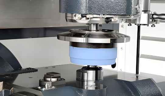
মাত্রা যাচাইয়ের জন্য CMM পরীক্ষা
NDT লুকিয়ে থাকা দোষগুলি খুঁজে পায়। কিন্তু মাত্রা নির্ভুলতা সম্পর্কে কী বলা যায়? যখন এয়ারোস্পেস উপাদানগুলির সহনশীলতা ±৫ মাইক্রনের মধ্যে হয়—যা মানব চুলের প্রস্থের প্রায় ১/২০ অংশ—তখন আপনার প্রয়োজন হয় এমন পরিমাপ ব্যবস্থা যা সেই নির্ভুলতার সঙ্গে মিলে যায়। এখানে আসে স্থানাঙ্ক পরিমাপ যন্ত্র (CMM)।
মাত্রা পরীক্ষার ক্ষেত্রে CMM পরীক্ষা এখন স্বর্ণের মানদণ্ড হয়ে উঠেছে, যা অতুলনীয় নির্ভুলতা, পুনরাবৃত্তিযোগ্যতা এবং ট্রেসেবিলিটি প্রদান করে। এই উন্নত ব্যবস্থাগুলি X, Y এবং Z—এই তিনটি লম্ব অক্ষ বরাবর প্রোবগুলিকে সরায় এবং উপাদানের পৃষ্ঠ থেকে নির্ভুল বিন্দু ডেটা সংগ্রহ করে, যা পরে CAD মডেল বা প্রকৌশল অঙ্কনের সঙ্গে তুলনা করা হয়।
কী কারণে এয়ারোস্পেস অ্যাপ্লিকেশনগুলিতে সিএমএম পরীক্ষা অপরিহার্য?
- অসাধারণ নির্ভুলতা: আধুনিক সিএমএম সিস্টেমগুলি স্ট্যান্ডার্ড সরঞ্জামের জন্য ±১ থেকে ±৫ মাইক্রোমিটার পর্যন্ত পরিমাপের নির্ভুলতা প্রদান করে, যেখানে অতি-নির্ভুল মেশিনগুলি সাব-মাইক্রোন স্তরে পৌঁছায়।
- জটিল জ্যামিতির ক্ষমতা: সিএমএমগুলি ফ্রি-ফর্ম পৃষ্ঠ, কঠোর টলারেন্সযুক্ত প্রোফাইল এবং জটিল বৈশিষ্ট্যগুলি পরিমাপ করে যা ঐতিহ্যগত গেজগুলি সঠিকভাবে মূল্যায়ন করতে পারে না।
- সম্পূর্ণ জিডি&টি বিশ্লেষণ: জিওমেট্রিক ডাইমেনশনিং অ্যান্ড টলারেন্সিং যাচাইকরণ নিশ্চিত করে যে অংশগুলি শুধুমাত্র মৌলিক মাত্রাগুলি নয়, বরং সমস্ত অবস্থানগত, আকৃতিগত এবং অভিমুখিক প্রয়োজনীয়তা পূরণ করে।
- স্বয়ংক্রিয় স্ক্যানিং: প্রোগ্রাম করা রুটিনগুলি উচ্চ-গতির, পুনরাবৃত্তিযোগ্য পরীক্ষার অনুমতি দেয় যা অপারেটরের পরিবর্তনশীলতা কমায় এবং উৎপাদন হার বৃদ্ধি করে।
ব্যবহারে, এয়ারোস্পেস উপাদানগুলি প্রায়শই এমন গুরুত্বপূর্ণ মাত্রা বজায় রাখতে হয় যা এরোডাইনামিক দক্ষতা এবং ক্লান্তি প্রতিরোধের নিশ্চয়তা দেয়—সাধারণত ±৫ থেকে ±১০ মাইক্রোমিটারের মধ্যে। সিএমএম পরীক্ষা পূর্ণ উৎপাদন চক্রের মাধ্যমে এই স্পেসিফিকেশনগুলি যাচাই করার জন্য প্রয়োজনীয় নির্ভুলতা এবং পুনরাবৃত্তিযোগ্যতা প্রদান করে।
নথিভুক্তকরণ এবং ট্রেসেবিলিটি প্রয়োজনীয়তা
এখানে এয়ারোস্পেস উৎপাদন ও সাধারণ ধাতুকাজের মধ্যে পার্থক্য লক্ষ্য করুন: প্রতিটি উপাদানের একটি নথিভুক্ত ইতিহাস রয়েছে, যা কাঁচামাল থেকে চূড়ান্ত গ্রহণের পর্যন্ত বিস্তারিতভাবে লিপিবদ্ধ করা হয়। এটি কোনো বৈরোক্র্যাটিক অতিরিক্ত ভার নয়—এটি বিমানের উড্ডয়নযোগ্যতা সার্টিফিকেশনের ভিত্তি। যদি কোনো বিমানের সেবা জীবনের দশ বছর পর কোনো সমস্যা দেখা দেয়, তবে তদন্তকারীদের সেই নির্দিষ্ট অংশটি কোন কাঁচামালের লট, কোন উৎপাদন প্রক্রিয়া এবং কোন পরীক্ষা ক্রম দ্বারা তৈরি হয়েছিল তা সঠিকভাবে ট্রেস করতে হবে।
এয়ারোস্পেস ধাতু নির্মাণের জন্য পরীক্ষা প্রোটোকল ক্রমটি সাধারণত নিম্নলিখিত ধাপগুলি অনুসরণ করে:
- আগত উপকরণ যাচাইকরণ: কাঁচামাল মিল সার্টিফিকেশনসহ আসে, যেখানে রাসায়নিক গঠন ও যান্ত্রিক বৈশিষ্ট্যগুলি নথিভুক্ত করা হয়। CMM সিস্টেমগুলি প্রক্রিয়াজাতকরণ শুরু করার আগে আগত ব্ল্যাঙ্কগুলি—যা ঢালাই, ফোর্জড বা নির্মিত হতে পারে—নির্দিষ্ট জ্যামিতিক প্রয়োজনীয়তা পূরণ করে কিনা তা যাচাই করে।
- প্রথম আর্টিকেল ইনস্পেকশন (FAI): প্রাথমিক উৎপাদন অংশটি একটি ব্যাপক মাত্রিক যাচাইকরণের মধ্য দিয়ে যায়, যা নিশ্চিত করে যে টুলিং, ফিক্সচার এবং প্রক্রিয়াগুলি সম্মতিসূচক উপাদান উৎপাদন করছে। এই বেসলাইন পরীক্ষা সম্পূর্ণ উৎপাদন সেটআপটির বৈধতা প্রমাণ করে।
- প্রক্রিয়া-মধ্য পরীক্ষা চেকপয়েন্টগুলি: মূল উৎপাদন পদক্ষেপগুলির পরে গুরুত্বপূর্ণ মাত্রাগুলি যাচাই করা হয়। শীট মেটাল ফ্যাব্রিকেশনের ক্ষেত্রে, এটি নিশ্চিত করে যে বাঁকানো এনক্লোজার বা লেজার-কাট প্রোফাইলগুলি পরবর্তী অপারেশনগুলিতে যাওয়ার আগে সমতলতা, কোণিকতা এবং প্রোফাইল সহনশীলতা পূরণ করে।
- অ-বিনষ্ট পরীক্ষা: উপযুক্ত অ-বিধ্বংসী পরীক্ষা (NDT) পদ্ধতিগুলি নির্দিষ্ট পর্যায়ে উপাদানের অখণ্ডতা যাচাই করে—বিশেষ করে ওয়েল্ডিং, তাপ চিকিত্সা বা অন্যান্য যেসব প্রক্রিয়ায় ত্রুটি সৃষ্টি হতে পারে, তার পরে।
- চূড়ান্ত মাত্রিক পরিদর্শন: CAD মডেল বা ইঞ্জিনিয়ারিং ড্রয়িংয়ের বিরুদ্ধে সম্পূর্ণ জ্যামিতিক যাচাইকরণ শিপমেন্টের আগে গ্রাহক-নির্দিষ্ট সমস্ত সহনশীলতা পূরণ করা হয়েছে কিনা তা নিশ্চিত করে।
- পৃষ্ঠের সম্পূর্ণতা যাচাই: প্রোফাইলোমিটারগুলি পৃষ্ঠের খারাপ অবস্থা (Ra মান) পরিমাপ করে যাতে শেষ পৃষ্ঠটি নির্দিষ্টকরণ পূরণ করে—যা ক্লান্তি জীবন এবং এরোডাইনামিক কর্মক্ষমতার জন্য অত্যন্ত গুরুত্বপূর্ণ।
- ডকুমেন্টেশন প্যাকেজ সংগ্রহ: সমস্ত পরিদর্শন প্রতিবেদন, উপকরণ সার্টিফিকেশন, অ-বিধ্বংসী পরীক্ষা (NDT) ফলাফল এবং প্রক্রিয়া রেকর্ডগুলি সম্পূর্ণ ট্রেসযোগ্যতা সমর্থন করে এমন স্থায়ী পণ্য ডকুমেন্টেশনে সংকলিত হয়।
এই গঠিত পদ্ধতিটি একাধিক উদ্দেশ্য পূরণ করে। এটি পরবর্তী অপারেশনগুলির মাধ্যমে মাত্রাগত বিচ্যুতিগুলি জমা হওয়ার আগেই তা ধরা দেয়। এটি পরিসংখ্যানগত প্রক্রিয়া নিয়ন্ত্রণ (SPC) ডেটা তৈরি করে যা প্রবণতাগুলি প্রকাশ করে এবং চলমান উন্নতির সুযোগ প্রদান করে। এবং এটি নথিভুক্ত প্রমাণ তৈরি করে যা নিরীক্ষকরা—এবং চূড়ান্তভাবে, প্রমাণীকরণ কর্তৃপক্ষগুলি—উড়ানের জন্য উপাদানগুলি অনুমোদন করার জন্য প্রয়োজন করে।
ফলাফলগুলি নিজেই কথা বলে। যখন নির্মাতারা তাদের কাজের প্রবাহের মধ্যে কঠোর CMM পরিদর্শন বাস্তবায়ন করে, তখন মাত্রাগত উৎপাদন হার ৯৩ শতাংশ থেকে বৃদ্ধি পেয়ে ৯৯ শতাংশ হয় এবং অ-অনুরূপতা ও পুনরায় কাজ করার হার ৪০ শতাংশের বেশি হ্রাস পায়।
মান নিয়ন্ত্রণ প্রোটোকলগুলি যাচাইকরণের কাঠামো প্রতিষ্ঠা করে। কিন্তু এয়ারোস্পেস নির্মাণের সবচেয়ে চ্যালেঞ্জিং দিকটি হলো এই কাজটিকে এতটাই প্রযুক্তিগতভাবে জটিল করে তোলা অনন্য প্রকৌশল চ্যালেঞ্জগুলির সমাধান করা।
এয়ারোস্পেস নির্মাণের অনন্য চ্যালেঞ্জগুলির সমাধান
আপনি দেখেছেন কীভাবে সার্টিফিকেশনগুলি কাজ করে এবং কেন মান নিয়ন্ত্রণ গুরুত্বপূর্ণ। কিন্তু এখানে হলো যা এয়ারোস্পেস প্রকৌশলীদের রাতের ঘুম হারায়: উড়ানের আসল ভৌত নীতিগুলি এমন পরিস্থিতি সৃষ্টি করে যা সাধারণ নির্মিত যন্ত্রাংশগুলিকে ধ্বংস করে দিতে পারে। বিমানের পাতলা ধাতব পাত নির্মাণ শুধুমাত্র নির্ভুলতার বিষয় নয়—এটি হলো এমন উপাদান তৈরি করা, যা অন্য কোনো শিল্পের দ্বারা চাহিদা করা হয় না এমন পরিবেশে টিকে থাকতে পারে।
একটি সাধারণ ফ্লাইট-ক্রিটিক্যাল উপাদান কী অভিজ্ঞতা অর্জন করে তা বিবেচনা করুন। ক্রুজিং উচ্চতায়, বহিরাবরণী পৃষ্ঠগুলি প্রায় -৬০°সেলসিয়াস তাপমাত্রার সম্মুখীন হয়। এদিকে, ইঞ্জিনের গরম অংশগুলি ১,০০০°সেলসিয়াসের বেশি তাপমাত্রায় পৌঁছায়। একটি একক কাঠামোগত সদস্য তার সেবা জীবন জুড়ে মিলিয়ন সংখ্যক পীড়ন চক্রের সম্মুখীন হতে পারে। আর এসব ঘটে যখন বায়ুমণ্ডলীয় অবস্থা শুষ্ক মরুভূমির বাতাস থেকে শুরু করে লবণযুক্ত উপকূলীয় আর্দ্রতা পর্যন্ত পরিবর্তিত হয়। এগুলো কোনো তাত্ত্বিক চিন্তা নয়—এগুলো হল এয়ারোস্পেস নির্মাণ চ্যালেঞ্জগুলির সংজ্ঞা নির্ধারণ করে এমন প্রকৌশলগত বাস্তবতা।
তাপীয় প্রসারণ নিয়ন্ত্রণ: তাপমাত্রার চরম পরিসরের মধ্যে
কল্পনা করুন এমন একটি উপাদান যার ক্রায়োজেনিক জ্বালানি সিস্টেমের তাপমাত্রা (-২৫৩°সেলসিয়াস, তরল হাইড্রোজেনের জন্য) থেকে ইঞ্জিনের গরম অংশের তাপমাত্রা (৭০০°সেলসিয়াসের বেশি) পর্যন্ত নিষ্পাপভাবে কাজ করা আবশ্যিক। যখন উপকরণগুলি উত্তপ্ত হয়, তখন সেগুলি প্রসারিত হয়; আর যখন ঠান্ডা হয়, তখন সংকুচিত হয়। এই তাপীয় চক্রগুলি জয়েন্টগুলিতে ফাটল সৃষ্টি করতে পারে, ফাস্টেনারগুলিকে ঢিলে করতে পারে এবং সূক্ষ্মভাবে যন্ত্রচালিত পৃষ্ঠগুলিকে বিকৃত করতে পারে।
এটি বিমান চলাচল শিল্পের জন্য ধাতু নির্মাণে কেন গুরুত্বপূর্ণ? কারণ বিভিন্ন উপাদান বিভিন্ন হারে প্রসারিত হয়। যখন একটি গঠনমূলক যোগস্থলে অ্যালুমিনিয়াম টাইটানিয়ামের সংস্পর্শে আসে, তখন তাপমাত্রা পরিবর্তনের ফলে বিভিন্ন হারে সরণ ঘটে, যা ফিটিং ও কার্যকারিতা ক্ষুণ্ণ করতে পারে। বিমান চলাচল প্রকৌশলীদের ডিজাইনের সময় এই তাপীয় প্রসারণ গুণাঙ্কগুলি বিবেচনা করতে হবে—এবং নির্মাতাদের এমন যোগস্থল তৈরি করতে হবে যা ব্যর্থতা ছাড়াই এই সরণকে সহন করতে পারে।
অনুযায়ী অরেঞ্জ কাউন্টি থার্মাল ইন্ডাস্ট্রিজ , বেশ কয়েকটি কারণে বিমান চলাচল শিল্পের তাপ ব্যবস্থাপনা বিশেষভাবে চ্যালেঞ্জিং:
- সংকুচিত স্থানে উচ্চ তাপ ঘনত্ব: যেহেতু বিমান চলাচল শিল্পের উপাদানগুলি ছোট ও শক্তিশালী হয়ে উঠছে, তাই এদের উৎপন্ন তাপ বৃদ্ধি পাচ্ছে এবং শীতলীকরণের জন্য প্রয়োজনীয় স্থান হ্রাস পাচ্ছে। উন্নত তাপ স্থানান্তর পদ্ধতি ছাড়া তাপমাত্রা হঠাৎ বৃদ্ধি পেলে সিস্টেমের দ্রুত ক্ষয় ঘটে।
- উপাদানভেদে ভিন্ন তাপীয় প্রয়োজনীয়তা: বিভিন্ন সিস্টেম উপাদানের ভিন্ন ভিন্ন তাপমাত্রা সীমা রয়েছে। একটি তাপ ব্যবস্থাপনা পদ্ধতিকে এই সমস্ত সীমাকে একসাথে সমর্থন করতে হবে।
- ভর এবং ওজনের সীমাবদ্ধতা: এয়ারোস্পেস শিল্পে প্রতিটি গ্রামই গুরুত্বপূর্ণ। শীতলীকরণ সমাধানগুলি হালকা হতে হবে—প্রকৌশলীরা প্রায়শই উন্নত ল্যাটিস কাঠামো এবং উচ্চ-দক্ষতাসম্পন্ন তাপ বিনিময়কারী ব্যবহার করেন যাতে ওজন বৃদ্ধি না করেই কার্যকারিতা অপটিমাইজ করা যায়।
- চাপ হ্রাস এবং সিস্টেমের দক্ষতা: শীতলীকরণ চ্যানেলগুলি চাপ হ্রাসের কারণে কম দক্ষ হয়ে পড়ে। চ্যানেলের দৈর্ঘ্য, পৃষ্ঠের খারাপ মসৃণতা এবং তরল গতিবিদ্যা—এই সমস্ত কারকই কার্যকারিতাকে প্রভাবিত করে, ফলে নকশা এবং তরল মডেলিংয়ের জন্য সাবধানতাপূর্ণ পদ্ধতি প্রয়োজন।
নির্মাতাদের জন্য, এটি নির্দিষ্ট প্রয়োজনীয়তায় রূপান্তরিত হয়: তাপীয় প্রসারণকে বিবেচনা করে নির্ভুল মাত্রিক নিয়ন্ত্রণ, যুগ্ম উপাদান নির্বাচন যা আপেক্ষিক প্রসারণ কমিয়ে দেয়, এবং তাপমাত্রার চরম পরিস্থিতিতেও অখণ্ডতা বজায় রাখতে পৃষ্ঠ চিকিত্সা। উদাহরণস্বরূপ, রকেট ইঞ্জিনের দেয়ালের কাছাকাছি কাজ করে এমন উপাদানগুলি মাইক্রোচ্যানেলের মধ্য দিয়ে উচ্চ-গতির হাইড্রোজেন প্রবাহিত করে তাপীয় চাপ কমিয়ে ইঞ্জিনের আয়ু দ্বিগুণ করতে পারে।
উচ্চ-চক্র অ্যাপ্লিকেশনে ক্লান্তি আয়ুর জন্য নকশা করা
বিমানের ডানা কতবার উড়ানের সময় বাঁকে যায়, তা ভাবুন। টেকঅফ, ল্যান্ডিং, টার্বুলেন্স এবং সাধারণ ক্রুজ অবস্থার সময় গঠনমূলক উপাদানগুলি পুনরাবৃত্ত লোডিং ও আনলোডিংয়ের শিকার হয়—যা কখনও কখনও বিমানের সেবা জীবনে কয়েক মিলিয়ন চক্রের মতো হতে পারে। এই পুনরাবৃত্ত চাপ ক্লান্তি সৃষ্টি করে, যা একটি প্রগতিশীল অবক্ষয় যা কোনো উপাদানের চূড়ান্ত শক্তির অনেক নীচে চাপে ব্যর্থতার দিকে নিয়ে যেতে পারে।
প্রকাশিত গবেষণা ম্যাটেরিয়ালস টুডে: প্রোসিডিংস ব্যাখ্যা করে কেন ক্লান্তি অধ্যয়ন অত্যন্ত গুরুত্বপূর্ণ: "বিমানের গঠনমূলক ব্যর্থতা প্রধানত অ-স্ট্যাটিক লোডিংয়ের অধীনে ক্লান্তি জনিত ব্যর্থতার কারণে ঘটে। সুতরাং, বিমানের গঠনমূলক উপাদানগুলির ক্লান্তি জীবন মূল্যায়ন বিমান গঠন ডিজাইন করার সময় প্রাথমিক বিবেচনা হয়ে ওঠে।"
এটি এয়ারোস্পেস ফ্যাব্রিকেশনের জন্য কী অর্থ বহন করে? পৃষ্ঠের শেষাবস্থা (সারফেস ফিনিশ) অত্যন্ত গুরুত্বপূর্ণ। প্রতিটি আঁচড়, টুল মার্ক বা খাঁজযুক্ত কিনারা ফাটল সৃষ্টির সম্ভাব্য স্থান হয়ে ওঠে। উচ্চ-চক্র ক্লান্তি (HCF) আয়ু অনুমান করার পদ্ধতিগুলি—যার মধ্যে বাসকুইনের সমীকরণের উপর ভিত্তি করে পদ্ধতিগুলিও অন্তর্ভুক্ত—প্রকৌশলীদের নির্দিষ্ট লোডিং শর্তে উপাদানগুলি কতক্ষণ টিকবে তা নির্ধারণে সহায়তা করে। কিন্তু ফ্যাব্রিকেশনের গুণগত মান সরাসরি এই অনুমানগুলিকে প্রভাবিত করে।
এয়ারোস্পেস ধাতব ফ্যাব্রিকেটরদের জন্য ক্লান্তি সংক্রান্ত প্রধান বিবেচ্য বিষয়গুলি হল:
- পৃষ্ঠের অখণ্ডতাঃ বার-মুক্ত কিনারা এবং মসৃণ পৃষ্ঠের শেষাবস্থা (Ra ০.৪ µm-এর নিচে) ফাটল গঠনকে ত্বরান্বিত করে এমন পীড়ন কেন্দ্রগুলিকে ন্যূনতম করে।
- অবশিষ্ট চাপ ব্যবস্থাপনা: উৎপাদন প্রক্রিয়াগুলি উপকারী সংকোচন পীড়ন বা ক্ষতিকর প্রসারণ পীড়ন উভয়ই সৃষ্টি করতে পারে—উপযুক্ত প্রক্রিয়া নির্বাচন এবং পোস্ট-প্রসেসিং অত্যাবশ্যক।
- উপাদান বৈশিষ্ট্য যাচাইকরণ: গবেষণা নিশ্চিত করেছে যে ক্লান্তি ফাটল বৃদ্ধি (FCG) হারগুলি পীড়ন অনুপাত এবং গড় পীড়ন স্তরের উপর নির্ভর করে। পরীক্ষার মাধ্যমে যাচাই করা হয় যে ফ্যাব্রিকেট করা উপাদানগুলি পূর্বানুমান করা ক্লান্তি আয়ুর সাথে মিলে যায়।
- উপাদান লটগুলির ট্রেসেবিলিটি: যেহেতু বিভিন্ন উপাদান ব্যাচে সামান্য পার্থক্য দেখা যেতে পারে, সম্পূর্ণ ট্রেসেবিলিটি উপাদানের উৎস এবং সেবার সময় তার কার্যকারিতার মধ্যে সম্পর্ক স্থাপন করে।
ফ্যাটিগ ডিজাইনে ভুল করার পরিণতি কী? সাধারণত ফ্যাটিগ ব্যর্থতা চাপ কেন্দ্রীভূত অঞ্চলে ফাটল সৃষ্টি হওয়া দিয়ে শুরু হয়, যা পুনরাবৃত্ত লোডিংয়ের কারণে ঘটে—এবং চূড়ান্ত ব্যর্থতা হঠাৎ ঘটে, প্রায়শই কোনো সতর্কতা ছাড়াই।
বিভিন্ন বায়ুমণ্ডলীয় অবস্থার জন্য ক্ষয় প্রতিরোধী ক্ষমতা
কল্পনা করুন যে একটি বিমান একদিন উপকূলীয় বিমানবন্দর থেকে চলাচল করে এবং পরের দিন মরুভূমির পরিবেশ থেকে। এটি আর্দ্রতা-প্রবণ নিম্ন বায়ুমণ্ডলের মধ্য দিয়ে আরোহণ করে, তারপর এমন উচ্চতায় ভ্রমণ করে যেখানে আর্দ্রতা জমে যায়। অবতরণের সময়, ঠান্ডা পৃষ্ঠে ঘনীভবন তৈরি হয়। ভেজা এবং শুষ্ক, লবণাক্ত এবং পরিষ্কারের মধ্যে এই ক্রমাগত চক্রাকারে ক্ষয়জনিত চ্যালেঞ্জ তৈরি করে যা সাধারণ শিল্প কারখানা কখনও সম্মুখীন হয় না।
উপাদান নির্বাচন কিছু ক্ষয়রোধ সংক্রান্ত উদ্বেগ মিটায়—উন্নত ক্ষয় প্রতিরোধ সম্পন্ন অ্যালুমিনিয়াম মিশ্র ধাতু, টাইটানিয়ামের প্রাকৃতিক অক্সাইড সুরক্ষা এবং বায়ুমণ্ডলীয় প্রক্ষেপণের জন্য ডিজাইন করা স্টেইনলেস স্টিলের বিভিন্ন প্রকার। কিন্তু উৎপাদন প্রক্রিয়াগুলি এই সহজাত সুরক্ষাগুলিকে ক্ষুণ্ণ করতে পারে। ওয়েল্ডিং-এর তাপ-প্রভাবিত অঞ্চলগুলি আন্তঃশস্য ক্ষয়ের প্রতি সংবেদনশীল হয়ে উঠতে পারে। অপ্রশিক্ষিত পৃষ্ঠ চিকিত্সা অরক্ষিত অঞ্চল রেখে দেয়। কাটিং তরল বা হ্যান্ডলিং-এর মাধ্যমে দূষণ ক্ষয়কারী আক্রমণ শুরু করতে পারে।
বিমান শিল্পের জন্য ক্ষয় প্রতিরোধ প্রয়োজন উৎপাদন প্রক্রিয়াজুড়ে সতর্কতা—দূষণ প্রতিরোধে উপযুক্ত উপাদান হ্যান্ডলিং, ফর্মিং অপারেশনের পর উপযুক্ত পৃষ্ঠ চিকিত্সা এবং নির্দিষ্টক্রম অনুযায়ী প্রয়োগ করা সুরক্ষামূলক কোটিং। সমুদ্র বা উচ্চ আর্দ্রতা পরিবেশের জন্য নির্ধারিত উপাদানগুলি প্রতিটি উৎপাদন পদক্ষেপে অতিরিক্ত বিবেচনা প্রয়োজন।
বিমান শিল্পের ওয়েল্ডিং পদ্ধতি এবং তাদের গুরুত্বপূর্ণ প্রয়োজনীয়তা
মহাকাশ বিমান শিল্পের ধাতুগুলি যুক্ত করার সময় ঝুঁকি আরও বেশি হতে পারে না। H&K Fabrication অনুসারে, "বিমানের উপাদানগুলি চিরকাল কম্পন, দ্রুত চাপ পরিবর্তন, তাপমাত্রা পরিবর্তন এবং জ্বালানির সংস্পর্শের মতো চাপের সম্মুখীন হয়। এই পরিবেশে যদি কোনো ওয়েল্ডিং ব্যর্থ হয়, তবে তা কেবল একটি ছোটখাটো ত্রুটি নয়; এটি মিশন এবং মানুষের নিরাপত্তাকে ঝুঁকির মধ্যে ফেলতে পারে।"
এই কারণেই মহাকাশ বিমান শিল্পের ওয়েল্ডিং-এ বিশেষায়িত পদ্ধতির প্রয়োজন—এবং এই কারণেই ওয়েল্ডারদের উড়ান-সম্পর্কিত গুরুত্বপূর্ণ উপাদানগুলির সংস্পর্শে আসার আগে নির্দিষ্ট সার্টিফিকেশন অর্জন করতে হয়। মহাকাশ বিমান শিল্পে ব্যবহৃত প্রধান ওয়েল্ডিং পদ্ধতিগুলি নিম্নরূপ:
- TIG ওয়েল্ডিং (GTAW): মহাকাশ বিমান শিল্পে সবচেয়ে ব্যাপকভাবে ব্যবহৃত হাতে করা ওয়েল্ডিং পদ্ধতি। এটি তাপ এবং পুডল আকারের উপর চমৎকার নিয়ন্ত্রণ প্রদান করে, যা পাতলা উপাদান এবং প্রতিক্রিয়াশীল ধাতুগুলির জন্য অপরিহার্য। ওয়েল্ডাররা প্রায়শই টাইটানিয়াম এবং অন্যান্য প্রতিক্রিয়াশীল মিশ্র ধাতুগুলিকে দূষণ থেকে রক্ষা করার জন্য গ্যাস ট্রেইলিং শিল্ড বা পার্জিং ব্যবহার করেন।
- ইলেকট্রন বীম ওয়েল্ডিং (EBW): ভ্যাকুয়ামের মধ্যে সম্পাদন করা হয়, ইলেকট্রন বিম ওয়েল্ডিং (EBW) ন্যূনতম বিকৃতির সাথে গভীর ওয়েল্ড পেনিট্রেশন অর্জন করে। এই পদ্ধতিটি ইঞ্জিন উপাদান এবং কাঠামোগত মহাকাশযানের অংশ—বিশেষ করে টারবাইন ব্লেডের মতো অংশগুলিতে, যেখানে ওয়েল্ডের অখণ্ডতা চরমভাবে গুরুত্বপূর্ণ, তার জন্য অত্যন্ত উপযুক্ত।
- লেজার বিম ওয়েল্ডিং (LBW): এটি অত্যন্ত ফোকাস করা শক্তি ব্যবহার করে পাতলা উপকরণে সূক্ষ্ম ও নির্ভুল ওয়েল্ড তৈরি করে। LBW প্রায়শই সেন্সর উপাদান, মহাকাশ ইলেকট্রনিক্সের আবরণ এবং ইঞ্জিনের পাতলা-গেজ উপাদানের মতো অংশগুলির জন্য স্বয়ংক্রিয়ভাবে ব্যবহৃত হয়, যেখানে তাপ ইনপুট সর্বনিম্ন রাখা আবশ্যিক।
- ফ্রিকশন স্টার ওয়েল্ডিং (এফএসডব্লিউ): এটি একটি সলিড-স্টেট পদ্ধতি যা ধাতুগুলিকে গলানো ছাড়াই যুক্ত করে—উপাদানটি সম্পূর্ণ প্রক্রিয়াজুড়ে এর গলনাঙ্কের নীচেই থাকে। যেহেতু ধাতু গলে না, তাই বিকৃতি এবং ফাটলের ঝুঁকি সর্বনিম্ন হয়, ফলে FSW বিমানের প্যানেল এবং মহাকাশযানের সংযোজন সহ বৃহৎ অ্যালুমিনিয়াম কাঠামোর জন্য আদর্শ।
- রেজিস্ট্যান্স ওয়েল্ডিং: যখন বিমানের কাঁচা ত্বক বা ফ্রেম সংযোজনের মতো উৎপাদনে হাজার হাজার অভিন্ন ওয়েল্ডের প্রয়োজন হয়, তখন এটি ব্যবহৃত হয়। স্বয়ংক্রিয়করণ মহাকাশ প্রযুক্তির অ্যাপ্লিকেশনগুলির জন্য প্রয়োজনীয় সামঞ্জস্য নিশ্চিত করে।
এয়ারোস্পেস ওয়েল্ডাররা একবার সার্টিফাই করে বিষয়টি ভুলে যান না—দক্ষতা নিয়মিতভাবে বেন্ড টেস্ট, রেডিওগ্রাফিক পরীক্ষা বা অলট্রাসনিক মূল্যায়নের মাধ্যমে প্রমাণ করতে হয়। অনেক কারখানায় ওয়েল্ডারদের প্রতিটি নির্দিষ্ট জয়েন্ট এবং যে উপাদান গ্রুপে তারা কাজ করেন তার জন্য পৃথকভাবে যোগ্যতা অর্জন করতে হয়।
এয়ারোস্পেস ওয়েল্ডিং এবং সাধারণ ফিউশন জয়েনিং-এর মধ্যে পার্থক্য কী? ডকুমেন্টেশনের প্রয়োজনীয়তা অসাধারণ। ওয়েল্ডিং প্যারামিটার, ফিলার ম্যাটেরিয়াল, শিল্ডিং গ্যাসের বিশুদ্ধতা এবং প্রি-হিট ও পোস্ট-হিট চিকিত্সা—সমস্ত কিছুই অনুমোদিত পদ্ধতিতে নির্দিষ্ট মতো ঠিকভাবে অনুসরণ করতে হয়। এমনকি ফিলার রডের উপর একটি দূষণজনিত আঙুলের ছাপও শূন্যতা বা সূক্ষ্ম ফাটল সৃষ্টি করতে পারে, যা উড়ানের চাপে আরও খারাপ হয়ে যায়।
এয়ারোস্পেস ওয়েল্ডাররা AWS D17.1 (এয়ারোস্পেস অ্যাপ্লিকেশনের জন্য ফিউশন ওয়েল্ডিং), AMS ওয়েল্ডিং স্পেসিফিকেশন এবং NADCAP বিশেষ প্রক্রিয়া অ্যাক্রিডিটেশন সহ কঠোর ফ্রেমওয়ার্কের অধীনে কাজ করেন। এই মানগুলি ওয়েল্ডিং পদ্ধতির যোগ্যতা প্রমাণীকরণ, ওয়েল্ডারের কর্মক্ষমতা যোগ্যতা প্রমাণীকরণ এবং ব্যাপক রেকর্ড রাখার প্রয়োজনীয়তা নির্দেশ করে। শিল্পের ভাষায়: প্রতিটি ওয়েল্ড শুধুমাত্র দৃশ্যগতভাবে পরিষ্কার হওয়ার পাশাপাশি প্রমাণযোগ্য হতে হবে।
এয়ারোস্পেস ওয়েল্ডার হওয়ার পথটি এই চাহিদাগুলিকে প্রতিফলিত করে। ওয়েল্ডাররা সাধারণত TIG, MIG এবং স্টিক ওয়েল্ডিং-এর মূল দক্ষতা দিয়ে শুরু করেন, পরে ধাতুবিদ্যা এবং ওয়েল্ডিং তত্ত্বের জ্ঞান বিকাশ করেন। ধাতুগুলি তাপের প্রতি কীভাবে প্রতিক্রিয়া করে—শস্য গঠন, তাপ-প্রভাবিত অঞ্চল, ফাটলের ঝুঁকি এবং ফিলার সামঞ্জস্য—এই বিষয়গুলি ওয়েল্ডিং প্রযুক্তির মতোই গুরুত্বপূর্ণ হয়ে ওঠে।
উপযুক্ত উপকরণ নির্বাচন, নির্মাণ প্রযুক্তি এবং বিশেষায়িত ওয়েল্ডিং-এর মাধ্যমে এই প্রকৌশলগত চ্যালেঞ্জগুলি সমাধান করার পর, পরবর্তী বিবেচ্য বিষয় হলো কীভাবে এই দক্ষতাগুলি নির্দিষ্ট বিমান সিস্টেম এবং উপাদানগুলিতে প্রয়োগ করা হয়।
বিমান ব্যবস্থার মধ্যে এয়ারোস্পেস ফ্যাব্রিকেশন অ্যাপ্লিকেশন
এখন আপনি যখন উপকরণ, প্রযুক্তি এবং গুণগত প্রয়োজনীয়তা বুঝতে পেরেছেন—তবে এই সমস্ত কিছু আসলে একটি বিমানে কীভাবে একত্রিত হয়? প্রতিটি বিমানে বিভিন্ন ব্যবস্থা রয়েছে, যার প্রত্যেকটির নিজস্ব ফ্যাব্রিকেশন প্রয়োজনীয়তা রয়েছে। যেমন, যে ফিউজেলেজ প্যানেলটি যাত্রীদের ডিকম্প্রেশন থেকে রক্ষা করে, তার বৈশিষ্ট্যগুলি একটি ইঞ্জিন ন্যাকেল কম্পোনেন্টের চেয়ে ভিন্ন, যা ১,৩০০°ফারেনহাইট এর এক্সহস্ট গ্যাসের প্রতিরোধ করে।
এই ব্যবস্থা-নির্দিষ্ট প্রয়োজনীয়তাগুলি বুঝতে পারলে আপনি বুঝতে পারবেন কেন বিমানের ধাতব ফ্যাব্রিকেশন এত বিশেষায়িত। এটি আরও প্রকাশ করে যে কেন এয়ারোস্পেস কম্পোনেন্ট নির্মাণে ডিজাইন ইঞ্জিনিয়ারিং, উপকরণ নির্বাচন এবং ফ্যাব্রিকেশন বাস্তবায়নের মধ্যে এত নির্ভুল সমন্বয় প্রয়োজন। আসুন বিমানের প্রধান অংশগুলি ঘুরে দেখি এবং প্রতিটি অংশের বৈশিষ্ট্যগুলি অনুসন্ধান করি।
ফিউজেলেজ প্যানেল ফ্যাব্রিকেশন প্রয়োজনীয়তা
ভাবুন যে ফিউজেলেজ আসলে কী করে। এটি একটি চাপ ধারণকারী পাত্র—যখন বিমান ৩৫,০০০ ফুট উচ্চতায় উড্ডয়ন করে যেখানে পরিবেশগত চাপ সমুদ্রপৃষ্ঠের চাপের প্রায় এক-চতুর্থাংশ, তখনও কেবিনের উচ্চতা বজায় রাখে। প্রতিটি ফ্লাইটের সময় এই ধ্রুব চাপারোপ-অপসারণ চক্র বিমানের ধাতব অংশগুলিকে দশক ধরে টিকিয়ে রাখার জন্য ক্লান্তি-আবদ্ধ লোড সৃষ্টি করে।
অনুযায়ী এয়ারবাস , আধুনিক বিমান যেমন A350-এ অনেক গঠনমূলক উপাদানের জন্য কম্পোজিট কভার ব্যবহার করা হয়, কিন্তু বিমানের শরীরের সমস্ত অংশে ধাতব উপাদানগুলি এখনও অপরিহার্য। ফিউজেলেজ নির্মাণে একাধিক স্থান ও সরবরাহকারী জড়িত, যেখানে চূড়ান্ত সংযোজনের আগে বিভিন্ন সুবিধায় উপাদানগুলি তৈরি করা হয়।
সাধারণত ফিউজেলেজের উপাদানগুলি এবং তাদের নির্মাণ বিবেচনাগুলি হল:
- স্কিন প্যানেল: সাধারণত অ্যালুমিনিয়াম মিশ্র ধাতু (2024 বা 7075) যা এরোডাইনামিক আকৃতি বজায় রাখতে সঠিক আকৃতিতে গঠন করা প্রয়োজন এবং কোটি কোটি চাপ চক্রের মধ্য দিয়ে ক্লান্তি প্রতিরোধ করতে সক্ষম হতে হবে।
- ফ্রেম এবং স্ট্রিঙার: গঠনমূলক শক্তিকারক যা চাপ পাত্রের মধ্যে লোডগুলি বিতরণ করে। অ্যালুমিনিয়াম বিলেট থেকে সিএনসি মেশিনিং সঠিক লোড স্থানান্তরের জন্য মাত্রিক নির্ভুলতা নিশ্চিত করে।
- দরজার পরিবেষ্টনী এবং জানালার ফ্রেম: উচ্চ-চাপ সংকেন্দ্রণের এলাকা যেখানে উন্নত উপাদান বৈশিষ্ট্য এবং সূক্ষ্ম পরীক্ষা প্রয়োজন—প্রায়শই টাইটানিয়াম বা সংবলিত অ্যালুমিনিয়াম গঠন।
- স্প্লাইস জয়েন্ট এবং ডাবলার: প্যানেলগুলি যেখানে সংযুক্ত হয়, সেখানে ফাস্টেনার ইনস্টলেশনের জন্য সঠিক ছিদ্র প্যাটার্ন এবং পৃষ্ঠ প্রস্তুতির প্রয়োজন।
- ফ্লোর বীম এবং সিট ট্র্যাক: যাত্রী ও মালপত্রের লোড বহন করতে হবে এবং চাপ পাত্রের সাথে গঠনগত একীকরণ বজায় রাখতে হবে।
ফিউজেলেজ নির্মাণকে বিশেষভাবে চ্যালেঞ্জিং করে কী? প্রতিটি প্যানেলকে পাশের অংশগুলির সাথে নিখুঁতভাবে মিলতে হবে—২০০ ফুট দীর্ঘ বিমানের মধ্যে সহনশীলতা দ্রুত জমা হয়। আর কারণ ফিউজেলেজ একটি চাপ পাত্র, তাই যেকোনো উৎপাদন ত্রুটি পুনরাবৃত্ত চাপ প্রয়োগের অধীনে সম্ভাব্য ব্যর্থতার বিন্দু হয়ে ওঠে।
ওয়িং গঠন এবং নিয়ন্ত্রণ পৃষ্ঠ নির্মাণ
উইংস শুধুমাত্র উত্থান প্রদান করে না—এগুলো জটিল গঠনমূলক সংযোজন, যার মধ্যে জ্বালানি ট্যাঙ্ক, নিয়ন্ত্রণ ব্যবস্থা এবং ভারবহনকারী উপাদান অন্তর্ভুক্ত থাকে যেগুলো উড়ানের বলগুলিকে ফিউজেলেজে স্থানান্তরিত করে। ম্যাগেলান এয়ারোস্পেস যেমন বর্ণনা করেছে, উইং সংযোজনগুলো ২ মিটার থেকে ২২ মিটার দৈর্ঘ্য পর্যন্ত উপাদান নিয়ে গঠিত, যার উৎপাদন, যন্ত্রকরণ, চিকিত্সা এবং সংযোজনের জন্য সমন্বিত বৈশ্বিক সরবরাহ শৃঙ্খলের প্রয়োজন হয়।
উইং উপাদানের শ্রেণীগুলো পরীক্ষা করলে নির্মাণের জটিলতা স্পষ্ট হয়ে ওঠে:
- স্পার (সামনের, মধ্যবর্তী, পিছনের এবং আন্তঃস্থিত): দৈর্ঘ্যভিত্তিক প্রাথমিক ভারবহনকারী সদস্য। ২২ মিটার পর্যন্ত বৃহৎ স্পারগুলো দীর্ঘ-বেড সিএনসি মেশিনিং কেন্দ্র, বহু-প্যালেট ৫-অক্ষ মেশিন এবং টার্টারিক সালফিউরিক অ্যানোডাইজ (টিএসএ) ও পেইন্ট ফিনিশিং সহ ব্যাপক পৃষ্ঠচিকিত্সা প্রয়োজন করে।
- পাঁজর: উইং-এর আকৃতি বজায় রাখে এবং স্পারগুলোতে বল স্থানান্তর করে এমন কর্ড-দিগবর্তী গঠনমূলক সদস্য। ছোট রিবগুলো (০.৫–২ মিটার) ৩ থেকে ৫-অক্ষ মেশিনিং এবং সর্বোচ্চ সরঞ্জাম কার্যকারিতা নিশ্চিত করার জন্য জিরো-পয়েন্ট ফিক্সচারিং সহ নমনীয় উৎপাদন ব্যবস্থা ব্যবহার করে।
- অগ্রভাগ ও পশ্চাৎভাগ অ্যাসেম্বলিগুলি: নির্ভুল কনটুর নিয়ন্ত্রণ প্রয়োজনীয় এরোডাইনামিক পৃষ্ঠ। মাঝারি আকারের উপাদানগুলি (২-৪.৫ মিটার) ১০০% ফিড রেটে সিএনসি প্রোগ্রাম ব্যবহার করে উচ্চ-গতির ৫-অক্ষ মিলিং পদ্ধতিতে তৈরি করা হয়, যেখানে কোনও মানুষের হস্তক্ষেপ প্রয়োজন হয় না।
- নিয়ন্ত্রণ পৃষ্ঠ (এইলেরন, ফ্ল্যাপ, স্পয়লার): গতিশীল এরোডাইনামিক উপাদান যার জন্য হালকা গঠন, নির্ভুল হিঞ্জ সাইডিং এবং এরোডাইনামিক লোডের অধীনে আকৃতি বজায় রাখার ক্ষমতা সম্পন্ন পৃষ্ঠের প্রয়োজন হয়।
- অ্যাক্সেস প্যানেল: অভ্যন্তরীণ সিস্টেমগুলিতে রক্ষণাবেক্ষণের প্রবেশাধিকার প্রদান করে যখন কাঠামোগত অখণ্ডতা এবং এরোডাইনামিক মসৃণতা বজায় থাকে।
ম্যাগেলানের ক্ষমতাগুলি বিমানের কাঠামোগত নির্মাণের প্রয়োজনীয়তাগুলি প্রদর্শন করে: নকশা প্রকৌশল (যার মধ্যে পীড়ন ও ক্লান্তি বিশ্লেষণ অন্তর্ভুক্ত), ২৩ মিটার পর্যন্ত জটিল সিএনসি মেশিনিং, ২২ মিটার ক্রোম অ্যানোডাইজিং ট্যাঙ্কসহ ব্যাপক পৃষ্ঠ চিকিত্সা, এবং এএফডি, পিএফডি, এমএফডি, কঠোরতা ও পরিবাহিতা পরীক্ষণসহ অ-বিধ্বংসী পরীক্ষা।
ইঞ্জিন উপাদানের জন্য উপাদান ও প্রক্রিয়া নির্বাচন
যদি ফিউজেলেজ নির্মাণে ক্লান্তি প্রতিরোধের প্রয়োজন হয় এবং ওয়িং উৎপাদনে স্কেলের প্রয়োজন হয়, তবে ইঞ্জিন উপাদানগুলি অন্য কোনও বিমান সিস্টেমের চেয়ে বেশি তাপীয় ও যান্ত্রিক সীমা অতিক্রম করে। টারবাইন অংশগুলি ৭০০°সেলসিয়াসের বেশি তাপমাত্রায় হাজার হাজার আরপিএম-এ ঘুরছে—এমন অবস্থা যা সাধারণ উপকরণগুলিকে ধ্বংস করে দেয়।
অনুযায়ী ম্যাগেলান এয়ারোস্পেসের ন্যাসেল এক্সহস্ট সিস্টেম ক্ষমতা; এই পণ্যগুলি প্রধানত টাইটানিয়াম ও নিকেল মিশ্র ধাতুতে তৈরি সংযুক্ত যৌগিক অংশ, যার মধ্যে শব্দ-সংশ্লিষ্ট ও শব্দ-বিহীন চিকিৎসা উভয়ই অন্তর্ভুক্ত। উৎপাদন প্রক্রিয়াগুলি নিম্নলিখিতগুলির সমন্বয় করে:
- এক্সহস্ট সিস্টেমের ডিজাইন ও নির্মাণ: তাপীয় ও এরোডাইনামিক কার্যকারিতার জন্য বিশেষায়িত প্রকৌশলের প্রয়োজন হয় এমন শব্দ-সংশ্লিষ্ট ও শব্দ-বিহীন উভয় কনফিগারেশন।
- ধাতব যোগাযোগ প্রযুক্তি: উচ্চ-তাপমাত্রার সুপারঅ্যালয়গুলির জন্য উপযুক্ত বিভিন্ন ওয়েল্ডিং, ব্রেজিং ও আঠালো বন্ধন পদ্ধতি।
- রাসায়নিক প্রক্রিয়াকরণ ও তাপ চিকিৎসা: প্রয়োজনীয় উপকরণ বৈশিষ্ট্য অর্জনের জন্য শূন্যস্থান ও বায়ুমণ্ডলীয় উভয় ধরনের তাপ চিকিৎসা।
- প্রচলিত ও অপ্রচলিত যন্ত্রকর্ম: কঠিন-যন্ত্রকর্মযোগ্য সুপারঅ্যালয়ের জন্য ইডিএম এবং বিশেষায়িত পদ্ধতি।
- হানিকম্ব উৎপাদন: শব্দ পণ্যের জন্য অভ্যন্তরীণভাবে উৎপাদিত ধাতব লেজার-ওয়েল্ডেড হানিকম্ব।
- জটিল ফর্মিং অপারেশন: বাল্জ ফর্মিং, এক্সপানশন ফর্মিং এবং ফ্লো/শিয়ার ফর্মিং—জটিল ন্যাসেল জ্যামিতি তৈরি করতে।
ইঞ্জিন ন্যাসেল এবং এক্সহস্ট নির্মাণ হল বিমান চলাচল শিল্পের সবচেয়ে প্রযুক্তিগতভাবে চ্যালেঞ্জিং উপাদান নির্মাণের মধ্যে একটি। চরম তাপমাত্রা, জটিল জ্যামিতি এবং কঠিন-যন্ত্রকর্মযোগ্য উপকরণের সংমিশ্রণের ফলে বিশেষায়িত সরঞ্জাম, প্রমাণিত প্রক্রিয়া এবং সুপারঅ্যালয়ের আচরণ সম্পর্কে গভীর বিশেষজ্ঞতা সম্পন্ন অপারেটরদের প্রয়োজন হয়।
ল্যান্ডিং গিয়ার অ্যাসেম্বলিজ: যেখানে শক্তি আঘাতের সম্মুখীন হয়
ল্যান্ডিং গিয়ার উপাদানগুলি একটি অনন্য চ্যালেঞ্জের মুখোমুখি হয়: এগুলি অবতরণের সময় বিশাল আঘাত লোড শোষণ করতে হবে, যদিও এগুলি সংকুচিত এবং তুলনামূলকভাবে হালকা থাকতে হবে। যেমন ডানা বা ফিউজেলেজ উপাদানগুলি ধীরে ধীরে লোড প্রয়োগের সম্মুখীন হয়, তেমনি ল্যান্ডিং গিয়ার অ্যাসেম্বলিগুলি প্রতিটি অবতরণ চক্রে হঠাৎ ও তীব্র চাপের সম্মুখীন হয়।
ম্যাগেলান এয়ারোস্পেস ব্যাখ্যা করে যে, ল্যান্ডিং গিয়ার উপাদান ও কিটগুলি তাদের হার্ড মেটাল মেশিনিং বিভাগের মূল পণ্য, যা নির্দিষ্ট প্রয়োজনীয়তা সমর্থন করার জন্য সূক্ষ্ম সহনশীলতায় উৎপাদন করা হয়। নির্মাণ পদ্ধতিটি নিম্নলিখিত বিষয়গুলিতে গুরুত্ব আরোপ করে:
- নমনীয় উৎপাদন পদ্ধতি (FMS) মেশিনিং কেন্দ্র: উচ্চ সরঞ্জাম দক্ষতার উপর মনোনিবেশ করে, যার ফলে মেশিনের ব্যবহার প্রায় ৯৫% পর্যন্ত হতে পারে।
- প্রক্রিয়া-মধ্যে প্রোবিং: মেশিনের মধ্যেই অংশ ও সরঞ্জামগুলির পরিমাপ এবং ক্যালিব্রেশন সম্পাদন করে উৎপাদন প্রক্রিয়াজুড়ে মাত্রিক নির্ভুলতা নিশ্চিত করা হয়।
- জিরো-পয়েন্ট দ্রুত পরিবর্তন পদ্ধতি: ফিক্সচার সেটআপ কমিয়ে জটিল জ্যামিতিক আকৃতির দক্ষ উৎপাদন সম্ভব হয়।
- স্ট্যান্ডার্ডাইজড টুলিং: বিভিন্ন অংশের মধ্যে একই টুলিং ব্যবহার করা হয়, যার ফলে সর্বোচ্চ নমনীয়তা এবং এক-টুকরো প্রবাহ উৎপাদন সম্ভব হয়।
- একীভূত কিটিং ও যানবাহন ব্যবস্থাপনা: সমাবেশ কার্যক্রমের জন্য সম্পূর্ণ উপাদান সেটগুলি সঠিক সময়ে পৌঁছানো নিশ্চিত করে।
ল্যান্ডিং গিয়ার তৈরি সাধারণত উচ্চ-শক্তির স্টিল অ্যালয় এবং টাইটানিয়াম ব্যবহার করে—এই উপকরণগুলি আঘাত শোষণের জন্য প্রয়োজনীয় শক্তি এবং গ্রহণযোগ্য ওজন উভয়ই প্রদান করে। এই উপাদানগুলির জন্য নির্ভুলতার প্রয়োজনীয়তা অসাধারণ, কারণ এগুলি যেসব ভার শোষণ করে তার ফলে অন্যান্য কম শক্তিসম্পন্ন গঠনগুলি বিকৃত হয়, তারপরও এগুলি সঠিক সামঞ্জস্য বজায় রাখতে এবং কাজ করতে সক্ষম হতে হবে।
বাণিজ্যিক বনাম প্রতিরক্ষা প্রয়োজনীয়তা: কী পরিবর্তন হয়?
আপনি হয়তো ধরে নিয়েছেন যে বাণিজ্যিক ও প্রতিরক্ষা মহাকাশ তৈরি মূলত একই—একই উপকরণ, একই নির্ভুলতা, একই মান ব্যবস্থা। ব্যবহারিক ক্ষেত্রে, বিশেষ করে ডকুমেন্টেশনের গভীরতা এবং নিরাপত্তা প্রোটোকলে উল্লেখযোগ্য পার্থক্য বিদ্যমান।
অনুযায়ী Engineering.com আন্তর্জাতিক অস্ত্র পরিবহন নিয়ন্ত্রণ বিধিমালা (ITAR) প্রায় সমস্ত মহাকাশ উৎপাদনে প্রযোজ্য, কারণ বাণিজ্যিক বিমানের জন্য তৈরি অনেক উপাদান সামরিক সংস্করণেও ব্যবহৃত হয়। এটি বহুস্তরীয় অনুপালন প্রয়োজনীয়তা তৈরি করে:
- কর্মচারী সংক্রান্ত বিধিনিষেধ: প্রতিরক্ষা কার্যক্রমগুলি প্রায়শই আইটিএআর (ITAR) অনুসরণ করার প্রয়োজন হয়, যার অর্থ প্রযুক্তিগত তথ্যে প্রবেশাধিকার রাখা কর্মচারীদের অবশ্যই মার্কিন নাগরিক হতে হবে অথবা নির্দিষ্ট বসবাসের মানদণ্ড পূরণ করতে হবে।
- নথিপত্রের গভীরতা: প্রতিরক্ষা চুক্তিগুলি সাধারণত বাণিজ্যিক কার্যক্রমের তুলনায় আরও ব্যাপক প্রক্রিয়া ডকুমেন্টেশন, উপকরণ ট্রেসেবিলিটি এবং পরিদর্শন রেকর্ডের প্রয়োজন হয়।
- নিরাপত্তা প্রোটোকল: প্রতিরক্ষা কাজের জন্য সুবিধা প্রবেশ নিয়ন্ত্রণ, সাইবার নিরাপত্তা ব্যবস্থা এবং তথ্য পরিচালনা পদ্ধতিগুলি চুক্তিবদ্ধ প্রয়োজনীয়তা হয়ে ওঠে।
- সরবরাহকারী শৃঙ্খল ব্যবস্থাপনা: প্রতিরক্ষা কার্যক্রমগুলি সকল সরবরাহকারী শৃঙ্খলের অংশগ্রহণকারীদের প্রয়োজনীয় অনুসরণ মানদণ্ড—যেমন AS9100D সার্টিফিকেশন—পূরণ করা নিশ্চিত করার প্রয়োজন হয়।
- পরিবর্তন নিয়ন্ত্রণ: প্রতিরক্ষা কার্যক্রমে উৎপাদন প্রক্রিয়া বা সরবরাহকারীদের পরিবর্তন করার জন্য প্রায়শই গ্রাহকের অনুমোদন প্রয়োজন হয়, যা বাস্তবায়নের পূর্বেই প্রয়োজনীয়।
উৎপাদনকারীদের জন্য, এটি বোঝায় যে প্রতিরক্ষা-সংশ্লিষ্ট মহাকাশ কাজের জন্য নিরাপত্তা অবকাঠামো, কর্মী যাচাইকরণ এবং অনুগততা কর্মসূচির ক্ষেত্রে অতিরিক্ত বিনিয়োগ প্রয়োজন। বাণিজ্যিক/প্রতিরক্ষা পার্থক্যটি উৎপাদন নির্ভুলতাকে প্রভাবিত করে না—উভয় ক্ষেত্রেই উৎকৃষ্টতা আবশ্যক। তবে প্রতিরক্ষা-সংশ্লিষ্ট কাজে প্রশাসনিক ও নিরাপত্তা সংক্রান্ত অতিরিক্ত প্রয়োজনীয়তা যুক্ত হয় যা বাণিজ্যিক কর্মসূচিগুলি আরোপ করে না।
এই সিস্টেম-নির্দিষ্ট এবং কর্মসূচি-নির্দিষ্ট প্রয়োজনীয়তাগুলির ব্যাপারে সচেতন হওয়া আপনাকে চূড়ান্ত বিবেচনার জন্য প্রস্তুত করে: কীভাবে এই বিভিন্ন চাহিদা পূরণ করতে সক্ষম একজন মহাকাশ উৎপাদন অংশীদারকে মূল্যায়ন ও নির্বাচন করবেন।
সঠিক মহাকাশ উৎপাদন অংশীদার নির্বাচন
আপনি উপকরণ, নির্মাণ পদ্ধতি, সার্টিফিকেশন এবং গুণগত প্রোটোকলগুলি অন্বেষণ করেছেন। এখন সেই সিদ্ধান্তের সময় এসেছে যা সবকিছুকে একত্রিত করে: এমন একটি এয়ারোস্পেস নির্মাণ পার্টনার নির্বাচন করা যিনি আসলে ডেলিভারি করতে পারেন। এটি সাধারণ মেশিন শপ নির্বাচনের মতো নয়—ভুল পছন্দ বিমান প্রোগ্রামগুলিকে ভূমিতে আটকে রাখতে পারে, অডিট ব্যর্থতা ঘটাতে পারে এবং বছরের পর বছর ধরে চলা উন্নয়ন কাজকে ঝুঁকির মধ্যে ফেলতে পারে।
সম্ভাব্য এয়ারোস্পেস উৎপাদন সরবরাহকারীকে মূল্যায়ন করার সময় আপনার কী খুঁজে নেওয়া উচিত? এর উত্তর কয়েকটি সার্টিফিকেশন বক্স চেক করার চেয়ে অনেক বেশি গভীরে যায়। আপনার প্রযুক্তিগত দক্ষতা, গুণগত ব্যবস্থা এবং কার্যক্রমিক নমনীয়তা পরীক্ষা করে এমন একটি ব্যবস্থিত পদ্ধতির প্রয়োজন। চলুন এই অপরিহার্য মূল্যায়ন মানদণ্ডগুলি বিশদভাবে বিশ্লেষণ করি যা যোগ্য এয়ারোস্পেস পার্টস নির্মাতাদের সেইসব প্রতিষ্ঠান থেকে পৃথক করে যারা শুধুমাত্র এয়ারোস্পেস দক্ষতা দাবি করে।
অংশীদারিত্বের আগে যাচাই করা আবশ্যিক সার্টিফিকেশনগুলি
কাগজপত্র দিয়ে শুরু করুন—কিন্তু সেখানেই থেমে যাবেন না। সার্টিফিকেশনগুলি আপনাকে জানায় যে একটি নির্মাতা ইতিমধ্যে পদ্ধতি প্রতিষ্ঠা করেছে; কিন্তু এগুলি গ্যারান্টি দেয় না যে সেই পদ্ধতিগুলি নিখুঁতভাবে কাজ করবে। গভীর অংশীদারিত্ব আলোচনা শুরু করার আগে যাচাই করার জন্য নিম্নলিখিত যোগ্যতা তালিকা দেখুন:
- AS9100D সার্টিফিকেশন: এয়ারোস্পেস ফ্যাব্রিকেশনের জন্য ন্যূনতম প্রয়োজনীয়তা। সার্টিফিকেটটি বর্তমান হওয়া, একটি স্বীকৃত রেজিস্ট্রার কর্তৃক প্রদান করা হওয়া এবং আপনার প্রয়োজনীয় নির্দিষ্ট কাজের পরিসর কভার করা—এই তিনটি বিষয় যাচাই করুন। সর্বশেষ সার্ভেইল্যান্স অডিটের ফলাফল জানতে অনুরোধ করুন।
- NADCAP অ্যাক্রিডিটেশন: কোন বিশেষ প্রক্রিয়াগুলি NADCAP অনুমোদন পেয়েছে তা পরীক্ষা করুন। যদি আপনার উপাদানগুলির জন্য হিট ট্রিটমেন্ট, ওয়েল্ডিং বা NDT প্রয়োজন হয়, তবে নির্মাতা প্রাসঙ্গিক NADCAP অ্যাক্রিডিটেশন ধারণ করেন—শুধুমাত্র ISO বা AS9100 কভারেজ নয়—তা নিশ্চিত করুন।
- AWS D17.1 ওয়েল্ডিং সার্টিফিকেশন: ফিউশন-ওয়েল্ডেড উপাদানের জন্য, ওয়েল্ডারদের AWS D17.1-এর বিশেষ সার্টিফিকেশন রয়েছে কিনা তা যাচাই করুন। সাধারণ ওয়েল্ডিং সার্টিফিকেশনগুলি এয়ারোস্পেস প্রয়োজনীয়তা পূরণ করে না।
- ITAR নিবন্ধন: যদি আপনার প্রোগ্রামে প্রতিরক্ষা সংক্রান্ত অ্যাপ্লিকেশন অন্তর্ভুক্ত থাকে, তবে রাজ্য বিভাগের সাথে সক্রিয় ITAR নিবন্ধন নিশ্চিত করুন। অনুমোদিত অনুপালন প্রোগ্রাম এবং সুবিধার নিরাপত্তা ব্যবস্থার প্রমাণ অনুরোধ করুন।
- গ্রাহক অনুমোদন: অনেক এয়ারোস্পেস OEM অনুমোদিত সরবরাহকারীদের তালিকা রাখে। জিজ্ঞাসা করুন যে কোন প্রাইম ঠিকাদারগুলো উৎপাদনকারীকে যোগ্যতা প্রমাণ করেছে—এবং কোন প্রক্রিয়াগুলোর জন্য।
সার্জেন্ট এয়ারোস্পেসের সরবরাহকারী মূল্যায়ন টেমপ্লেট অনুযায়ী, যোগ্যতা প্রাপ্ত সরবরাহকারীদের প্রমাণ হিসাবে "ইমেইলের মাধ্যমে এই অনুমোদনের প্রমাণ" প্রদান করা উচিত, যার মধ্যে সার্টিফিকেশন, নিবন্ধন এবং প্রযোজ্য NADCAP প্রক্রিয়া অনুমোদনের কপিগুলো অন্তর্ভুক্ত থাকবে। যদি কোনও উৎপাদনকারী বর্তমান সার্টিফিকেশন ডকুমেন্টেশন শেয়ার করতে দ্বিধা করে, তবে এটি একটি গুরুতর সতর্কতা সংকেত।
টেকনিক্যাল ক্ষমতা এবং সরঞ্জামের মূল্যায়ন
সার্টিফিকেশনগুলো প্রমাণ করে যে ব্যবস্থাগুলো বিদ্যমান। যন্ত্রপাতির ক্ষমতা নির্ধারণ করে যা আসলে সম্ভব। একজন নির্ভুল এয়ারোস্পেস মেশিনিং পার্টনার মূল্যায়ন করার সময় এই প্রযুক্তিগত বিষয়গুলো পরীক্ষা করুন:
- CNC মেশিন ক্ষমতা: সর্বোচ্চ পার্টের আকারগুলি কী কী? বহু-অক্ষ ক্ষমতা কেমন? সহনশীলতা (টলারেন্স) বিশেষকরণগুলি কী কী? ক্রস ম্যানুফ্যাকচারিং-এর মতো উন্নত সুবিধাগুলি বিভিন্ন এয়ারোস্পেস উপাদান পরিচালনা করার জন্য "বহু-স্পিন্ডল এবং স্লাইডিং হেড বহু-অক্ষ লেথ, সিএনসি মিলিং, ওয়্যার ইডিএম, গ্রাইন্ডিং এবং ল্যাপিং" প্রদান করা উচিত।
- উপকরণ বিশেষজ্ঞতা: তারা আপনার নির্দিষ্ট অ্যালয়গুলির সাথে কাজ করতে পারেন কি? টাইটানিয়াম, ইনকোনেল এবং উচ্চ-শক্তির অ্যালুমিনিয়াম—প্রতিটির জন্য বিশেষ মেশিনিং কৌশলের প্রয়োজন। কঠিন-মেশিনযোগ্য সুপারঅ্যালয়গুলির সাথে অভিজ্ঞতা সম্পর্কে জিজ্ঞাসা করুন।
- অভ্যন্তরীণ বিশেষ প্রক্রিয়া: তাপ চিকিৎসা, পৃষ্ঠ সমাপ্তি বা অ-বিধ্বংসী পরীক্ষা (NDT) কি সাইটের মধ্যেই সম্পন্ন হয়—না হলে নির্মাতা এই গুরুত্বপূর্ণ অপারেশনগুলি বাইরে ঠাউরে দেন? অভ্যন্তরীণ ক্ষমতাগুলি নিয়ন্ত্রণ এবং ট্রেসেবিলিটির উন্নত সুযোগ প্রদান করে।
- পরিদর্শন সরঞ্জাম: আপনার উপাদানগুলির নির্ভুলতা প্রয়োজনীয়তা অনুযায়ী সিএমএম (CMM) সিস্টেম, পৃষ্ঠ প্রোফাইলোমিটার এবং ক্যালিব্রেটেড গেজগুলি মিলতে হবে। পরিমাপের নির্ভুলতা এবং ক্যালিব্রেশন প্রোগ্রাম সম্পর্কে জিজ্ঞাসা করুন।
- টুলিং এবং ফিক্সচার ডিজাইন: বিমান চলাচল সংক্রান্ত যন্ত্রাংশগুলির জন্য প্রায়শই কাস্টম ওয়ার্কহোল্ডিং প্রয়োজন হয়। নির্মাতার ফিক্সচার ডিজাইনের ক্ষমতা এবং তারা কীভাবে নতুন সেটআপগুলি যাচাই করে—এই দুটি বিষয় মূল্যায়ন করুন।
একজন নির্মাতার সরঞ্জামের তালিকা আপনাকে বলে দেয় যে তিনি তাত্ত্বিকভাবে কী উৎপাদন করতে পারেন। তাঁর প্রক্রিয়া নিয়ন্ত্রণ নথিগুলি আপনাকে বলে দেয় যে তিনি কি ধারাবাহিকভাবে নির্দিষ্ট প্রয়োজনীয়তা পূরণ করছেন।
গুণগত ব্যবস্থা এবং সরবরাহ শৃঙ্খল ব্যবস্থাপনা
সার্টিফিকেশন এবং সরঞ্জামের পাশাপাশি, নির্মাতার প্রকৃত অপারেশন পদ্ধতি পরীক্ষা করুন। সার্জেন্ট সরবরাহকারী মূল্যায়ন শ্রেণিবদ্ধ গুণগত ব্যবস্থার সেই গুরুত্বপূর্ণ উপাদানগুলি চিহ্নিত করে যা নিরীক্ষকরা যাচাই করেন:
- নথিভুক্ত গুণগত ম্যানুয়াল: এটি কি বর্তমান, কর্মচারীদের জন্য প্রবেশযোগ্য এবং প্রাসঙ্গিক কর্তৃপক্ষ দ্বারা অনুমোদিত? ম্যানুয়ালটিতে অপারেশন, সংগঠনগত গঠন এবং প্রক্রিয়া মধ্যে সম্পর্কগুলি বর্ণনা করা উচিত।
- অভ্যন্তরীণ নিরীক্ষণ কর্মসূচি: নির্মাতা কি নথিভুক্ত ফলাফল এবং সংশোধনমূলক ব্যবস্থা সহ নিয়মিত অভ্যন্তরীণ নিরীক্ষণ পরিচালনা করেন? নিরীক্ষণ রেকর্ডগুলি কতদিন ধরে সংরক্ষণ করা হয়?
- উপ-স্তরের সরবরাহকারী নিয়ন্ত্রণ: সরবরাহকারীরা প্রদর্শিত দক্ষতা অনুযায়ী নির্বাচিত হয় কিনা? সময়ে সময়ে কর্মক্ষমতা পর্যালোচনা সহ একটি অনুমোদিত সরবরাহকারী রেজিস্টার আছে কিনা? গ্রাহকের সমস্ত প্রয়োজনীয়তা—যার মধ্যে মূল বৈশিষ্ট্যগুলি অন্তর্ভুক্ত—সাব-টিয়ার সরবরাহকারীদের কাছে প্রবাহিত হতে হবে।
- ট্রেসএবিলিটি সিস্টেম: তারা কি মিল সার্টিফিকেশন থেকে শুরু করে প্রতিটি উৎপাদন অপারেশন এবং চূড়ান্ত পরীক্ষা পর্যন্ত উপকরণের ট্রেস করতে পারে? প্রক্রিয়াজাতকরণ শুরু করার আগে কাঁচামাল বিশেষকরণের সাথে যাচাই করা উচিত।
- ক্যালিব্রেশন প্রোগ্রাম: সমস্ত পরিমাপক সরঞ্জাম NIST-ট্রেসেবল মানের সাথে ক্যালিব্রেট করা উচিত, যার মধ্যে নথিভুক্ত করা হয়েছে ক্যালিব্রেশনের পরিধি, পদ্ধতি এবং গ্রহণযোগ্যতার মানদণ্ড।
- অ-অনুরূপতা পরিচালনা: যখন সমস্যা দেখা দেয় তখন কী ঘটে? কার্যকর উৎপাদনকারীরা অ-অনুরূপ পণ্য চিহ্নিতকরণ, পৃথকীকরণ এবং নিষ্পত্তির জন্য নথিভুক্ত পদ্ধতি রাখে—এবং সমস্যা দেখা দিলে গ্রাহককে সময়মতো অবহিত করা হয়।
দ্রুত প্রোটোটাইপিং এবং স্কেলেবল উৎপাদন ক্ষমতা
এয়ারোস্পেস প্রোগ্রামগুলি সাধারণত পূর্ণ উৎপাদন পরিমাণে শুরু হয় না। উন্নয়ন পর্যায়ে দ্রুত প্রোটোটাইপিংয়ের ক্ষমতার প্রয়োজন—অর্থাৎ পরীক্ষামূলক উপাদানগুলি দ্রুত তৈরি করা, ডিজাইনগুলি যাচাই করা এবং পরীক্ষার ফলাফলের ভিত্তিতে পুনরাবৃত্তি করা। যেমন স্নোলাইন ইঞ্জিনিয়ারিং ব্যাখ্যা করে, "দ্রুত প্রোটোটাইপিং সেবাগুলি আপনার এয়ারোনটিক্যাল প্রোটোটাইপগুলির উন্নয়ন প্রক্রিয়াকে সহজতর করে... সিএডি ফাইল থেকে সরাসরি ত্বরিত সময়সূচীতে জটিল এয়ারোস্পেস প্রোটোটাইপগুলি তৈরি করে।"
প্রোটোটাইপিংয়ের ক্ষমতা মূল্যায়ন করার সময় নিম্নলিখিত বিষয়গুলি বিবেচনা করুন:
- উদ্ধৃতি প্রতিক্রিয়া সময়: নতুন পার্ট অনুরোধের জন্য নির্মাতা কত দ্রুত মূল্য ও লিড টাইম প্রদান করতে পারেন? উন্নয়ন প্রোগ্রামগুলি উদ্ধৃতির জন্য সপ্তাহ ধরে অপেক্ষা করতে পারে না।
- উৎপাদনের জন্য ডিজাইন (DFM) সমর্থন: ইঞ্জিনিয়ারিং কর্মীরা কি ডিজাইনগুলি পর্যালোচনা করেন এবং কার্যকারিতা কমানো ছাড়াই উৎপাদনযোগ্যতা উন্নত করার জন্য সংশোধন প্রস্তাব করেন? এই সহযোগিতা খরচ কমাতে এবং উৎপাদন সংক্রান্ত সমস্যা প্রতিরোধ করতে সাহায্য করতে পারে।
- প্রথম নমুনা পরীক্ষা (FAI) গতি: তারা প্রাথমিক উৎপাদন পার্টগুলি কত দ্রুত তৈরি করে এবং যাচাই করতে পারেন? দ্রুত FAI সম্পন্ন করা প্রোগ্রামের সময়সূচীকে ত্বরান্বিত করে।
- স্কেলেবিলিটি: প্রোটোটাইপিং সম্পর্কগুলি কি মাত্রায় উৎপাদনে সহজেই রূপান্তরিত হতে পারে? ক্রস ম্যানুফ্যাকচারিং-এর বর্ণনা অনুযায়ী, "কম এবং উচ্চ মাত্রার উৎপাদন উভয়ের জন্য নমনীয় ক্ষমতা" সম্পন্ন প্রস্তুতকারকদের খুঁজুন।
আকর্ষণীয়ভাবে, নির্ভুল ধাতব স্ট্যাম্পিংয়ের বিশেষজ্ঞতা প্রায়শই চাপসৃষ্টিকারী শিল্পখাতগুলিতে স্থানান্তরিত হয়। যাদের গাড়ি শিল্পের IATF 16949 সার্টিফিকেশন রয়েছে তাদের মধ্যে প্রায়শই গুণগত ব্যবস্থা এবং স্ট্যাম্পিং ক্ষমতা থাকে যা এয়ারোস্পেস অ্যাপ্লিকেশনের সাথে সরাসরি প্রাসঙ্গিক। শাওই (নিংবো) ধাতু প্রযুক্তি এই স্থানান্তরযোগ্যতার উদাহরণ হল—তাদের ৫-দিনের দ্রুত প্রোটোটাইপিং, ব্যাপক DFM সমর্থন এবং ১২-ঘণ্টার মধ্যে আনুমানিক মূল্য নির্ধারণের সময়সীমা, যা এয়ারোস্পেস উন্নয়ন প্রোগ্রামগুলির প্রয়োজনীয় সাড়া দেওয়ার ক্ষমতা প্রদর্শন করে। যদিও তাদের প্রধান ফোকাস হল গাড়ি শিল্পের স্ট্যাম্পিং, কিন্তু IATF 16949 সার্টিফিকেশনের ভিত্তিতে গড়ে ওঠা নির্ভুল উৎপাদন অবকাঠামো এবং গুণগত অনুশাসনগুলি এয়ারোস্পেস ব্র্যাকেট, ক্লিপ এবং শীট মেটাল উপাদানগুলির জন্য প্রযোজ্য ভিত্তি গড়ে তোলে।
অংশীদারিত্ব মূল্যায়ন চেকলিস্ট
কোনও এয়ারোস্পেস ফ্যাব্রিকেশন পার্টনার নির্বাচন চূড়ান্ত করার আগে, এই বিস্তারিত চেকলিস্টটি অনুসরণ করুন:
| মূল্যায়নের বিভাগ | জিজ্ঞাসা করতে হবে গুরুত্বপূর্ণ প্রশ্ন | অনুরোধ করা ডকুমেন্টেশন |
|---|---|---|
| প্রমাণীকরণ পোর্টফোলিও | বর্তমান AS9100D? প্রাসঙ্গিক NADCAP অ্যাক্রেডিটেশনগুলি? ITAR নিবন্ধিত? | বর্তমান প্রমাণপত্রগুলি, সর্বশেষ অডিট রিপোর্টগুলি, NADCAP মেরিট অবস্থা |
| ম্যাটেরিয়াল বিশেষজ্ঞতা | নির্দিষ্ট অ্যালয়গুলির সাথে অভিজ্ঞতা? অভ্যন্তরীণ ধাতুবিদ্যা জ্ঞান? | নমুনা প্রমাণপত্রগুলি, সদৃশ প্রকল্প থেকে উপাদান পরীক্ষা রিপোর্টগুলি |
| সরঞ্জামের ক্ষমতা | মেশিনের ক্ষমতা অংশের প্রয়োজনীয়তা পূরণ করে? সহনশীলতা ক্ষমতা নথিভুক্ত করা হয়েছে? | সরঞ্জামের তালিকা, ক্ষমতা অধ্যয়ন, প্রক্রিয়া ক্ষমতা ডেটা |
| গুণমানমূলক সিস্টেম | অভ্যন্তরীণ অডিটের ফলাফল? সংশোধনমূলক ব্যবস্থার কার্যকারিতা? গ্রাহক স্কোরকার্ড পারফরম্যান্স? | গুণগত ম্যানুয়ালের অংশবিশেষ, অভ্যন্তরীণ অডিট সারাংশ, গ্রাহক স্কোরকার্ড |
| সাপ্লাই চেইন ব্যবস্থাপনা | অনুমোদিত সরবরাহকারীদের তালিকা বজায় রাখা হয়েছে? সাব-টিয়ার তত্ত্বাবধান পদ্ধতি? | সরবরাহকারী ব্যবস্থাপনা পদ্ধতি, ফ্লো-ডাউন প্রয়োজনীয়তা |
| প্রোটোটাইপিংয়ের গতি | উদ্ধৃতি প্রত্যাবর্তনের সময়? ইঞ্জিনিয়ারিং DFM সমর্থন পাওয়া যায়? | প্রতিক্রিয়া সময় দেখানো নমুনা উদ্ধৃতি, DFM প্রতিক্রিয়ার উদাহরণ |
| উৎপাদন স্কেলিং | আয়তন বৃদ্ধির জন্য ক্ষমতা? চাপের অধীনে সামঞ্জস্যপূর্ণ লিড টাইম? | উৎপাদন ক্ষমতা তথ্য, ঐতিহাসিক সময়মতো ডেলিভারি মেট্রিক্স |
সঠিক এয়ারোস্পেস ফ্যাব্রিকেশন পার্টনার নির্বাচন করা শেষ পর্যন্ত আপনার প্রোগ্রামের প্রয়োজনীয়তা এবং নির্মাতার প্রদর্শিত ক্ষমতার মধ্যে সামঞ্জস্যের উপর নির্ভর করে। সার্টিফিকেশনগুলি প্রাথমিক যোগ্যতা প্রতিষ্ঠা করে। প্রযুক্তিগত ক্ষমতাগুলি বাস্তবায়নের সম্ভাবনা নির্ধারণ করে। এবং মান ব্যবস্থাগুলি সামঞ্জস্য নিশ্চিত করে। এবং অপারেশনাল নমনীয়তা—দ্রুত প্রোটোটাইপিং থেকে স্কেলেবল উৎপাদন পর্যন্ত—আপনার প্রোগ্রামকে বিকাশ থেকে পূর্ণ-হার উৎপাদন পর্যন্ত বিকশিত হতে দেয় যাতে সরবরাহকারী পরিবর্তন করা না হয়।
প্রতিটি উপাদান পদ্ধতিগতভাবে যাচাই করতে সময় নিন। ডকুমেন্টেশন অনুরোধ করুন। সম্ভব হলে সুবিধাগুলি পরিদর্শন করুন। আপনার প্রোগ্রামের সম্পূর্ণ জীবনচক্র জুড়ে বিস্তারিত পার্টনার মূল্যায়নে বিনিয়োগ করা লাভজনক—এটি গুণগত ত্রুটির হার কমায়, বিতরণ সময় নির্ভরযোগ্য করে এবং শুধুমাত্র সবচেয়ে কঠোর সার্টিফিকেশন প্রয়োজনীয়তা পূরণ করে এমন অডিট-প্রস্তুত ডকুমেন্টেশন নিশ্চিত করে।
বিমান ও মহাকাশ ধাতু নির্মাণ সম্পর্কিত প্রায়শই জিজ্ঞাসিত প্রশ্নসমূহ
১. বিমান ও মহাকাশ শিল্পে ফ্যাব্রিকেশন বলতে কী বোঝায়?
বিমান ও মহাকাশ ফ্যাব্রিকেশন হল বৃহত্তর বিমান সিস্টেমের অংশ হিসেবে ব্যবহৃত বিভিন্ন উপাদান—যেমন বিমানের ফ্রেম, ইঞ্জিন অংশ এবং গঠনমূলক অ্যাসেম্বলিগুলি—এর নির্ভুল উৎপাদন। সাধারণ ধাতু নির্মাণের বিপরীতে, বিমান ও মহাকাশ শিল্পের কাজে ±০.০০২ মিমি-এর মধ্যে টলারেন্স, টাইটানিয়াম ও ইনকোনেল-এর মতো বিশেষ ধাতুর বিষয়ে বিশেষজ্ঞ জ্ঞান এবং কাঁচামাল থেকে সম্পূর্ণ উৎপাদিত অংশ পর্যন্ত সম্পূর্ণ ট্রেসেবিলিটি প্রয়োজন। প্রতিটি উপাদানকে উড়ান নিরাপত্তা নিশ্চিত করতে FAA, EASA এবং আন্তর্জাতিক মানগুলি পূরণ করতে হবে।
২. ধাতু নির্মাণের তিনটি প্রকার কী কী?
ধাতু নির্মাণের তিনটি মৌলিক পদ্ধতি হলো কাটিং, বেন্ডিং এবং অ্যাসেম্ব্লিং। এয়ারোস্পেস অ্যাপ্লিকেশনগুলিতে, এই পদ্ধতিগুলি অত্যন্ত নির্ভুলভাবে সম্পাদন করা হয়, যেমন— সিএনসি মেশিনিং (±০.০০১ ইঞ্চি টলারেন্স পর্যন্ত), জটিল প্যানেল কাজের জন্য লেজার ও ওয়াটারজেট কাটিং, এবং টাংস্টেন ইনার্ট গ্যাস (টিআইজি), ইলেকট্রন বীম ও ফ্রিকশন স্টার ওয়েল্ডিং সহ বিশেষায়িত ওয়েল্ডিং প্রক্রিয়া। প্রতিটি পদ্ধতি নির্বাচন করা হয় উপাদানের ধরন, কম্পোনেন্টের জ্যামিতি এবং প্রমাণীকরণ প্রয়োজনীয়তা অনুযায়ী।
৩. এয়ারোস্পেস ধাতু কী?
এয়ারোস্পেস-গ্রেড ধাতুগুলি হল উড়ান-সম্পর্কিত গুরুত্বপূর্ণ অ্যাপ্লিকেশনের জন্য নকশা করা উচ্চ-কর্মক্ষমতাসম্পন্ন উপকরণ। এগুলির মধ্যে রয়েছে কাঠামোগত উপাদানের জন্য অ্যালুমিনিয়াম মিশ্র ধাতু (২০২৪, ৬০৬১, ৭০৭৫), ইঞ্জিন ও ল্যান্ডিং গিয়ারের যেসব অংশ ৫০০°সেলসিয়াস পর্যন্ত তাপমাত্রায় কাজ করে তাদের জন্য টাইটানিয়াম গ্রেড ৫, এবং টারবাইনের অংশগুলির জন্য নিকেল-ভিত্তিক সুপারঅ্যালয় যেমন ইনকোনেল ৭১৮, যা ৭০০°সেলসিয়াসের বেশি তাপমাত্রা সহ্য করতে পারে। এই সমস্ত উপকরণগুলি বিমানের কার্যকারিতা ও নিরাপত্তির জন্য আবশ্যিক অসাধারণ শক্তি-ওজন অনুপাত এবং ক্ষয় প্রতিরোধী বৈশিষ্ট্য প্রদান করে।
৪. এয়ারোস্পেস ধাতু নির্মাণের জন্য কোন সার্টিফিকেশন প্রয়োজন?
বিমান চলাচল শিল্পের জন্য উৎপাদন কার্যক্রমে একাধিক সার্টিফিকেশন একসাথে কাজ করা আবশ্যক: AS9100D হলো বিমান শিল্প-বিশেষ মান ব্যবস্থাপনা প্রমাণীকরণ, যা ISO 9001-এর উপর ভিত্তি করে গড়ে উঠেছে; NADCAP তাপ চিকিৎসা (হিট ট্রিটমেন্ট) এবং অ-বিধ্বংসী পরীক্ষণ (NDT) সহ বিশেষ প্রক্রিয়াগুলির বৈধতা যাচাই করে; AWS D17.1 ফিউশন ওয়েল্ডিং ক্ষমতার প্রমাণীকরণ প্রদান করে; এবং ITAR নিবন্ধন প্রতিরক্ষা কার্যক্রমে অংশগ্রহণের অনুমতি প্রদান করে। প্রধান ওইএম (OEM) গুলি সরবরাহকারীদের একাধিক প্রমাণপত্র ধারণ করতে বাধ্য করে, কারণ প্রতিটি প্রমাণপত্র সরবরাহ শৃঙ্খলে গুণগত মান, নিরাপত্তা এবং প্রক্রিয়া নিয়ন্ত্রণের বিভিন্ন দিককে কভার করে।
৫. বিমান চলাচল শিল্পের জন্য উৎপাদনকারীরা কীভাবে উপাদানের গুণগত মান নিশ্চিত করে?
বিমান চলাচল শিল্পের উৎপাদনে গুণগত নিশ্চয়তা বহুস্তরীয় পরিদর্শন প্রোটোকল অন্তর্ভুক্ত করে: মাত্রিক যাচাইয়ের জন্য ±১-৫ মাইক্রোমিটার নির্ভুলতা অর্জনকারী সিএমএম (CMM) পরিমাপ, লুকিয়ে থাকা ত্রুটিগুলি শনাক্ত করার জন্য অ-বিধ্বংসী পরীক্ষণ পদ্ধতি (আলট্রাসাউন্ড, এক্স-রে, ডাই পেনিট্রেন্ট), প্রোফাইলোমিটার ব্যবহার করে পৃষ্ঠের সমাপ্তি যাচাই, এবং সম্পূর্ণ ট্রেসযোগ্যতা নিশ্চিত করার জন্য ব্যাপক ডকুমেন্টেশন। প্রথম নমুনা পরিদর্শনগুলি উৎপাদন সেটআপগুলির বৈধতা যাচাই করে, অন্যদিকে পরিসংখ্যানগত প্রক্রিয়া নিয়ন্ত্রণ (SPC) উৎপাদন চক্রগুলির মধ্যে সামঞ্জস্যতা পর্যবেক্ষণ করে।